design and performance characterization of high …
TRANSCRIPT

DESIGN AND PERFORMANCE CHARACTERIZATION OF HIGH POWER DENSITY AIR-COOLED COMPACT CONDENSER HEAT EXCHANGERS
BY
NICHOLAS IAN MANISCALCO
DISSERTATION
Submitted in partial fulfillment of the requirements for the degree of Doctor of Philosophy in Mechanical Engineering
in the Graduate College of the University of Illinois at Urbana-Champaign, 2014
Urbana, Illinois
Doctoral Committee: Professor William P. King, Chair, Director of Research Professor Anthony M. Jacobi Professor John G. Georgiadis Professor Gregory S. Elliott

ABSTRACT
The current investigation reports the design, fabrication, and characterization of ultra-
compact air-cooled condenser heat exchangers with exceptional power density performance in
excess of 100 W/cm3. This exceptional heat exchanger performance is attributed to the
implementation of high-speed compressible air flow in circular microchannels and two-phase
condensation flow of refrigerant in rectangular minichannels to achieve high heat transfer
performance in a compact design. These advancements are enabled by recent developments in
micro-electric discharge machining to produce very high surface area compact heat exchanger
devices.
Air-cooled heat sinks have been identified as pivotal to the future of thermal management
of microelectronics in the 21st century. Air-cooling systems provide clear advantages in overall
ease of integration due to its availability and abundance over forced liquid cooling systems. The
enhancement of forced air flow is especially important because it generally represents the
dominant thermal resistance of the condenser. The implementation of high-speed compressible air
flow in microchannels permits investigation of flow conditions with exceptionally high heat
transfer coefficients. This investigation explores turbulent flow regime conditions for air-side
Reynolds numbers 8,000 < Re < 20,000, in high-density parallel arrangements of circular copper
microchannels, 355 and 520 μm in diameter.
Two-phase heat transfer technology is one of the most efficient methods of waste heat
removal in high power electronics cooling. It is especially advantageous in applications where size,
weight, and efficiency are important factors. Two-phase active cooling systems consist of an
evaporator and a condenser. Heat transfer performance in the evaporator is typically much higher
than in the condenser; consequently the condenser is the limiting component of the entire cooling
system. Improvements in condenser technology enable electronics systems to operate at a higher
power while reducing the overall cooling system size and weight. The condensation phase change
process in microchannels with high aspect ratios yields the formation of a thin film condensation
layer on the heat transfer wall, resulting in high heat transfer coefficients with little pressure drop
penalty. It is therefore of utmost importance that condensation phenomena, especially in high
aspect-ratio microchannels be experimentally investigated. This investigation employs
condensation in a parallel array of high-aspect ratio, 0.5 mm x 2 mm, rectangular minichannels.
ii

Compact cross flow heat exchangers are manufactured using novel micro-electro-
discharge machining to produce high-density, high aspect ratio microchannels in a copper alloy.
The heat exchanger performance is characterized for single-phase liquid and phase-change
condensation of a refrigerant. The heat exchangers are operated using single-phase liquid flow of
dielectric refrigerant R245fa at 80 °C and high-speed flow of air at ~25 °C to demonstrate a power
density performance of nearly 70 W/cm3. The heat exchangers are operated using two-phase
condensation of R245fa at 80 °C and high-speed flow of air at ~25 °C to achieve power density
performance > 175 W/cm3 and overall thermal resistance < 0.27 K/W.
Test methodologies were implemented for determination of the thermal-hydraulic
performance of these novel devices. Modeling and characterization of this system were
implemented using well-known methods and the results are compared with the corresponding
literature for microchannel fluid flow and heat transfer. The study of this system demonstrates an
advancement in the state-of-the-art in power density performance of compact air-cooled heat sinks.
Power dissipation rates > 1 kW and an overall thermal resistance of < 0.05 K/W are projected with
scaling of these methodologies in a 10 cm3 device.
iii
TABLE OF CONTENTS
LIST OF FIGURES .................................................................................................................... VI
LIST OF TABLES ................................................................................................................... VIII
LIST OF SYMBOLS .................................................................................................................. IX
CHAPTER 1: INTRODUCTION............................................................................................. 1
1.1 MOTIVATION .......................................................................................................................... 1
1.2 OBJECTIVES OF WORK ........................................................................................................... 3
1.3 STATE-OF-THE-ART IN HEAT SINK TECHNOLOGY ................................................................. 4
1.3.1 MICRO-MANUFACTURING OF HEAT EXCHANGERS .......................................................... 6
1.4 SINGLE-PHASE FLOW IN MICROCHANNELS ............................................................................ 7
1.4.1 SCALING EFFECTS IN MICROCHANNELS .......................................................................... 8
1.5 TWO-PHASE CONDENSATION IN RECTANGULAR MINICHANNELS ......................................... 14
1.6 STRUCTURE OF THESIS ......................................................................................................... 16
CHAPTER 2: DESIGN AND EXPERIMENTAL METHODS .......................................... 18
2.1 OVERVIEW ........................................................................................................................... 18
2.2 MODELING HEAT EXCHANGER PERFORMANCE .................................................................... 18
2.2.1 MODEL COMPARISON .................................................................................................... 21
2.3 MICRO-EDM MANUFACTURING OF MICRO-HEAT EXCHANGERS ........................................ 29
2.4 EXPERIMENTAL DESIGN ....................................................................................................... 33
2.4.1 AIR-SIDE TEST FACILITIES ............................................................................................ 34
2.4.2 REFRIGERANT-SIDE TEST FACILITIES ............................................................................ 35
2.4.3 EXPERIMENTAL PROCEDURE ......................................................................................... 38
2.5 EXPERIMENTAL METHODS ................................................................................................... 40
2.5.1 EXPERIMENTAL MEASUREMENTS .................................................................................. 43
2.5.2 EXPERIMENTAL UNCERTAINTY ..................................................................................... 46
2.6 CONCLUSIONS ...................................................................................................................... 47
CHAPTER 3: SINGLE PHASE PERFORMANCE............................................................. 49
3.1 OVERVIEW ........................................................................................................................... 49
iv

3.2 AIR-SIDE PRESSURE DROP ................................................................................................... 50
3.3 LIQUID REFRIGERANT-SIDE PRESSURE DROP ....................................................................... 55
3.4 HEAT EXCHANGER PERFORMANCE ...................................................................................... 60
3.4.1 DATA REDUCTION ......................................................................................................... 63
3.4.2 DETERMINATION OF THERMAL RESISTANCES ............................................................... 65
3.4.3 THERMAL CONDUCTION HEAT TRANSFER .................................................................... 71
3.5 PERFORMANCE COMPARISON ............................................................................................... 72
3.6 CONCLUSIONS ...................................................................................................................... 75
CHAPTER 4: PHASE CHANGE PERFORMANCE .......................................................... 77
4.1 OVERVIEW ........................................................................................................................... 77
4.2 CONDENSATION REFRIGERANT-SIDE PRESSURE DROP ......................................................... 77
4.3 HEAT EXCHANGER PERFORMANCE ...................................................................................... 81
4.3.1 TWO-PHASE CONDENSATION ........................................................................................ 83
4.3.2 THERMAL CONDUCTION HEAT TRANSFER .................................................................... 87
4.4 PERFORMANCE COMPARISON ............................................................................................... 88
4.5 CONCLUSIONS ...................................................................................................................... 89
CHAPTER 5: SCALING OF METHODOLOGY ................................................................ 91
CHAPTER 6: CONCLUSIONS ............................................................................................. 94
6.1 SIGNIFICANCE OF WORK ...................................................................................................... 94
6.2 CONCLUSIONS ...................................................................................................................... 96
6.3 RECOMMENDATIONS FOR FUTURE WORK ............................................................................ 97
REFERENCES ............................................................................................................................ 99
v

LIST OF FIGURES
Figure 2.1 Shows the predicted A) pressure drop and B) heat transfer coefficient for different
circular channel diameters as a function of Reynolds number as predicted by Kays and London experimental correlations. ....................................................................................... 19
Figure 2.2 A) The predicted frictional gradient predicted by Friedel model and B) convection coefficient predicted by Akers model for refrigerant R245fa in an 800 μm channel is shown................................................................................................................................................ 20
Figure 2.3 A) The heat transfer model is comprised a heat exchanger having 4 fins with adiabatic tips of length Lf. B) The cross sectional temperature distribution of the modeled heat exchanger. ............................................................................................................................. 23
Figure 2.4 The of fin efficiency as a function of Re is shown for 400 and 600 μm diameters on a 450 and 650 μm pitch for different fin lengths. .................................................................... 24
Figure 2.5. A) Power density for an air-side channel diameter of 400 µm over a range of refrigerant side convection coefficients are shown as a function of the air side convection coefficient for 1 and 2 refrigeration cross channels (CC). Heat exchangers with B) one cross channel and C) two refrigerant side cross channel were modeled in COMSOL using the same boundary conditions applied in the 1-D model............................................................ 25
Figure 2.6 A) 1 cm long circular air column with a diameter of 400 μm is simulated using FLUENT for an A) adiabatic wall and an B) isothermal wall at 80 °C. A 2-D cross section of the static pressure, static temperature, velocity magnitude, and fluid density are plotted as a function of the channel length for the case where the upstream stagnation pressure is 150 kPa at an inlet temperature of 293 K and the downstream outlet condition is 101 kPa. The no-slip condition at the channel walls is employed. ............................................................. 27
Figure 2.7 The cross flow compact heat exchanger design concept. A) Air flows through the circular microchannels and a dielectric refrigerant flows through the rectangular minichannels. B) The air side consists of an array of circular microchannels of diameter D and a center-to-center offset P. The refrigerant side consists of parallel rectangular minichannels with a cross sectional aspect ratio α=a/b. ....................................................... 28
Figure 2.8 Photographs of 1 cm3 devices and air-side microscope images. A) Device A and B) Device B. C) Photographs of the assembled manifold (left) air side and (right) both sides. 31
Figure 2.9 Surface roughness profile for the inside of a of circular cross section 6.2 mm in length is shown along with a table of summarizing the characteristic parameters of the roughness profile. ................................................................................................................................... 33
Figure 2.10 Schematic of experimental setup for A) air-side and B) refrigerant-side test facilities................................................................................................................................................ 38
Figure 2.11 Left) Variation between the temperatures for high velocity compressible fluid [Image adopted from [102]]. Right) General behavior of dynamic correction factors for gases [Image adopted from [105]]. ....................................................................................... 46
Figure 3.1 Contraction and Expansion loss coefficients for flow between inlet and outlet manifolds and the microchannels (A) αc < 1 and (B) 0.1 ≤ αc ≤ 1.0. [Image adapted from [78]]....................................................................................................................................... 51
Figure 3.2 A) Air-side pressure drop measurements for Device A and B as a function of Re. B) The measured apparent friction factors are compared to the isothermal compressible Fanno model as a function of Re. .................................................................................................... 53
vi
Figure 3.3 A) Single-phase refrigerant-side pressure drop decomposition for Device A and B as a function of mass flux at 60 and 80 °C. B) Experimentally determined refrigerant-side friction factors as a function of refrigerant-side Reynolds number. ..................................... 59
Figure 3.4 Heat rate density performance for Device A and B as a function of A) air-side Re and B) refrigerant-side mass flux. C) The overall thermal conductance is shown as a function of refrigerant mass flux for air-side condition where PA=689.5 kPa. ....................................... 62
Figure 3.5 A) Comparison of the measured air-side convection coefficients to the Sieder-Tate and Dittus-Boelter correlations. B) Comparison of the single-phase liquid refrigerant-side convection coefficients compared to Phillips laminar model and Pertukov turbulent flow model..................................................................................................................................... 70
Figure 3.6 The relative contributions of the thermal resistances are given as a function of refrigerant-side mass flux for the air side condition PA =689.5 kPa. .................................... 71
Figure 3.7 A) COP and Pumping power as a function of power dissipation in the heat exchangers with single-phase heating. B) The experimentally obtained j vs. f curve is compared to the Chilton-Colburn relation. ...................................................................................................... 74
Figure 4.1 Two-phase Refrigerant-side pressure drop measurements for Device A and B compared to the frictional of pressure drop predictions of the Friedel model, along with the pressure drop effects due to acceleration effects, expansion effects, and contraction effects................................................................................................................................................ 80
Figure 4.2 Heat rate power performance of Device A and Device B with two-phase refrigerant side heating at a mass flux of 750 kg/m2-s as a function of air-side Re. .............................. 82
Figure 4.3 Thermal conductance of Device A and Device B as a function of air-side Re. .......... 83 Figure 4.4 Experimentally reduced refrigerant-side convection coefficients as a function of the
heat flux compared to the Akers model for a refrigerant quality of x=1 and x=0. ............... 85 Figure 4.5 The total thermal resistance for A) Device A and B) Device B is decomposed into
constitutive terms accounting for air-side convective resistance, refrigerant-side convective resistance and the conduction resistance of the exchanger. .................................................. 86
Figure 5.1 A) Isometric photograph of 10 cm3 heat exchanger, Device C. Microscope images of B) Air-side and C) refrigerant-side are shown. ..................................................................... 91
Figure 5.2 Simulated power density power dissipation and overall thermal resistance for the range of expected air-side and refrigerant-side boundary conditions. .................................. 93
vii

LIST OF TABLES
Table 2.1 Comparison between 1-D fin model to the 3-D COMSOL model for several air side
and refrigerant side boundary conditions. ............................................................................. 26 Table 2.2 Summarizes the two 1-cm3 and one 10-cm3 heat exchanger designs manufactured using
µEDM manufacturing. .......................................................................................................... 30 Table 2.3 Measurement uncertainty of instruments. ..................................................................... 37 Table 2.4 Summary of the air-side and refrigerant-side characteristics of 1 cm3 manufactured
heat exchangers. .................................................................................................................... 40 Table 3.1 Air-side hydraulic characteristics and loss coefficients. ............................................... 51 Table 3.2 Refrigerant-side hydraulic characteristics and loss coefficients. .................................. 57 Table 3.3 Laminar flow friction factor in the entrance region of a rectangular duct with an aspect
ratio of 1:4 interpolated table from Phillips model [109]. .................................................... 58 Table 3.4 Table comparing modeling and experimental data for the two heat exchangers with
single-phase refrigerant heating. ........................................................................................... 73 Table 3.5 Single-phase refrigerant heating data for Device A and Device B are compared to the
expected values as calculated by the modeled thermal resistances and by the application of the experimental convection coefficients to a 3-D COMSOL model. .................................. 73
Table 4.1 Table comparing models and experimental data for the two heat exchangers with two-phase refrigerant heating. ...................................................................................................... 88
Table 4.2 Two-phase refrigerant heating data for Device A and Device B are compared to the expected values as calculated by the modeled thermal resistances and by the application of the experimental convection coefficients to a 3-D COMSOL model. .................................. 89
Table 5.1 Summary of the air-side and refrigerant-side characteristics of 10 cm3 manufactured heat exchangers. .................................................................................................................... 92
viii

LIST OF SYMBOLS
Roman Symbols
a speed of sound [m/s]
A area [m2]
cp specific heat capacity at constant pressure [J/kg-K]
cv specific heat capacity at constant volume [J/kg-K]
COP coefficient of performance
Dh, hydraulic diameter [m]
e specific internal energy [J/kg]
f fanning friction factor
F LMTD correction factor
G mass flux [kg/m2-s]
h heat transfer coefficient [W/m2-K]
i specific enthalpy [J/kg-K]
j Colburn factor
K dynamic recovery factor
Kc entrance pressure loss coefficient
Ke exit pressure loss coefficient
K(x) incremental pressure defect
k thermal conductivity [W/m-K]
Kn Knudsen number
L channel length [m]
Ma Mach number
m mass flow rate [kg/s]
Nc number of channels
Nu Nusselt number
P pressure [Pa]
P thermal effectiveness
PW wetted perimeter [m]
P0 stagnation pressure [Pa]
ix

ΔP differential pressure [Pa]
Po Poiseuille number
Pr Prandtl number
Q heat rate [W]
Q” heat flux [W/m2]
rh hydraulic radius [m]
R thermal resistance [K/W]
R heat capacity rate ratio
R specific gas constant [J/kg-K]
r recovery factor
Re Reynolds number
S conduction shape factor [m-1]
T temperature [K]
T0 stagnation temperature [K]
UA overall thermal conductance [W/K]
u velocity [m/s]
V volume [m3]
V volumetric flow rate [m3/s]
W pumping power [W]
x+ dimensionless axial distance
Greek Symbols
α aspect ratio, void fraction
β fin parameter
γ heat capacity ratio
fη fin efficiency
θ dimensionless temperature
λ mean free path
μ dynamic viscosity [kg/m-s]
x

ν kinematic viscosity [m2/s]
ρ density [kg/m3]
σ area ratio
χ fin parameter
Subscripts
a absolute
aw adiabatic wall
C cold
c cross-sectional
cv control volume
CF counter flow
char characteristic
cond conduction
exp experimental
f fluid
fg liquid-vapor
fr frontal area
g saturated vapor
H hot
in inlet
LM logarithmic mean
LO liquid only
m mean
max maximum
me measured
min minimum
out outlet
p probe
ref refrigerant
s surface
xi

sat saturation
VO vapor only
w wall
W wetted
xii

CHAPTER 1: INTRODUCTION
1.1 Motivation
Thermal management in electronics has been a key driver of heat transfer research for over
30 years [1-3]. Energy conversion and utilization are continuous but ever increasing processes for
sustainability and economic development. Heat exchangers are a universal component for
achieving energy conservation through enhanced heat transfer [4]. The issue of thermal
management in both military and commercial systems has become increasingly important due to
more powerful electronic processing capabilities and the resulting heat generation. Over the past
decade, average heat dissipation in chips and printed circuit boards has more than doubled [5, 6].
Modern electronic components are being asked to maintain higher performance at a lower heat
tolerance under more demanding climatic conditions. Issues such as increased energy demands,
space limitations, and material savings have highlighted the need for miniaturized light-weight
heat exchanger to high heat transfer for a given heat duty [1-4]. As heat exchangers employing
conventional channels (>3 mm) approach their margins for utility, microchannels (<1 mm)
represent the next step in heat exchanger development.
Thermal management of processors is an important field of study devoted to engineering
the removal of heat from these devices. Natural air and forced convection of air over the chip are
no longer capable of maintaining process temperatures below acceptable values. Heat transfer at
the electronics source is the primary driver of power electronics’ performance [7]. As such, a
majority of research on compact heat exchangers and phase-change electronics cooling has
focused on evaporation and boiling near the electronics being cooled [8-11]. Boiling in
microchannels for heat removal of computer chips has been shown to yield the lowest pumping
power and highest heat dissipation rates. Combining these technologies with vapor compression
refrigeration to enable high heat fluxes has been called for in the literature [12]. Saturation
conditions and flow rates can be controlled refrigeration systems to achieve a desirable range of
operation.
The majority of research in microchannel heat sinks focuses on heat removal from the chip
at the evaporator. As a result of this emphasis, the compactness and performance of the condenser
has been subsequently neglected. In a complete thermal system, the condenser and the evaporator
must work in concert; it is therefore essential that their capabilities be well matched. Space
1
restrictions impose a limit on the size and weight of refrigeration systems and are one of the most
challenging aspects of implementing these technologies. It is therefore imperative that the compact
design of all components in the cycle be considered in order to advance the technology [12].
The current research aims to bring compact condenser technology to parity with evaporator
technology. Almost all existing research on compact condensers has been driven by the HVAC
and automotive industries rather than electronics thermal management [13]. The development of
new applications in thermal management requires rapid cooling in confined spaces. Electronics
cooling, aerospace, MEMS for power electronics cooling, and space thermal management have
increased the number of applications requiring high heat transfer rates and fluid flows in relatively
small passages [1].
High-flux thermal management is a primary design concern for advanced defense devices
found in radars, directed-energy laser, and microwave weapon systems and avionics [14]. While
these devices follow the trend of escalating power density of commercial electronics, heat fluxes
from defense devices are projected to exceed 1000 W/cm2 [15]. This level of heat dissipation
exceeds the current trend in capabilities being developed by todays most advanced dielectric liquid
cooling systems, highlighting the need to develop novel cooling technologies. Defense electronic
systems fail to reach maximum device performance due to high thermal resistances [16]. Thermal
management hardware in advanced electronic systems accounts for a large fraction of the volume,
weight, and cost which restricts the efforts to transfer emerging electronic components to portable
applications. A considerable amount of research effort has been concentrated on using
microchannel heat sinks to reduce total thermal resistance. Today’s most effective cooling
solutions are usually based on microchannel coolant flows and jet impingement [17]. Decreasing
the hydraulic diameter has been a common tactic employed to significantly increasing the
convective heat transfer coefficients in order to achieve high performance power density
dissipation. Microchannel heat sinks are ideal for compact light-weight applications. However the
two key drawbacks associated with these devices are the high pressure drops and large temperature
gradients across the device.
Water, although cheap and abundant is ill suited for two-phase cooling of most
microelectronic applications because most silicon based microelectronics have a maximum
junction temperature around 85 °C, which lower than the boiling point of water at atmospheric
conditions. Therefore, low pressure dielectric refrigerants which are inherently safer when being
2

used near electrical connections must be studied. Implementation of low pressure dielectric
refrigerants offers the advantage of high heat fluxes at practical operating conditions.
This investigation presents an experimental analysis for compact microchannel condensers
for a miniature scale refrigeration system. The thermal-hydraulic performance of microchannel
condensers with high-speed air flow is enhances power density performance in a compact cross-
flow heat exchanger with single-phase and condensation phase-change refrigerant-side heating.
1.2 Objectives of Work
Heat transfer coefficients in microchannels are very high due to their small hydraulic
diameters. However previous researchers have been limited by low flow rates due to the high
pressure gradients incurred at these reduced channel diameters. For a given temperature rise, the
ability of the fluid stream to remove heat is limited by the thermal capacity of low fluid flow rates.
Therefore in order to improve the overall cooling performance multiple microchannels with short
lengths are recommended to reduce the overall pressure drop while exploiting the benefits of high
heat transfer and high flow rates. The incorporation of multiple channels in parallel with short path
lengths leads to a larger dominance of developing region effects when the heat transfer rate is high.
An overall pressure drop reduction will enable higher velocities to be explored, which provides
for the investigation of turbulent flow conditions with high heat transfer coefficients in
microchannels.
The main objective of this work is to design, fabricate, and characterize ultra-compact air-
cooled condenser heat exchangers with performance that exceeds a power density of 100
W/cm3 and a heat load 1 kW with an overall thermal resistance >0.05 K/W . The project
additionally aims to achieve heat flux at the refrigerant-air interface of 1 kW/cm2 or higher, at as
large a coefficient of performance as possible. The two-fluid exchanger incorporates high speed
air flow through metal microchannels to condense a high temperature dielectric refrigerant flowing
though microchannel passages in cross-flow. Modeling and characterization of this system was
performed using well-known methods and then compared with the corresponding literature on
microchannel flow and heat transfer. The study of this system provides broad and useful insights
for advancing the start-of-the-art in design and operation of compact air-cooled heat sinks.
The objectives of this work is can be broken into two main areas. The first area is focused
on modeling and design of the heat exchangers. This part also describe the fabrication of the
devices and the integration of the heat exchangers in the test facility. The second part of this work
3

is focused on the thermal and hydraulic performance characterization of the devices. The
objectives of the work are summarized as follows:
1. Design and Experimental Methods
a. Model heat exchanger performance
b. Select heat exchanger designs to meet performance metrics
c. Fabricate the heat exchangers
d. Construct test facilities
2. Heat exchanger characterization
a. Characterize thermal-hydraulic performance of air side
b. Characterize single-phase thermal-hydraulic performance of refrigerant-side
c. Characterize single-phase thermal-hydraulic performance of refrigerant-side
d. Compare performance metrics with reported literature
e. Summarize conclusions and impact of work
1.3 State-Of-The-Art in Heat Sink Technology
Research in the field of thermal fluidics at the microscale level has been steadily increasing
due to rapid growth in technological applications requiring high rates of heat transfer in small
volumes. Recent advances in microelectromechanical systems (MEMS) and advanced very large-
scale integration (VLSI) technologies have led to significant increases in the packing densities of
these devices and allow heat fluxes of up to 200 W/cm2 to be generated [18]. The automotive,
aerospace, chemical reactor, MEMS, and cryogenic industries are responsible for most of the
research and development of microchannel heat exchangers technologies. Thermal duty and
energy efficiency requirements have increased during this period and space constraints have
become more restrictive. The trend has been to focus on increasing the heat transfer rate per unit
volume [19]. Microchannel heat exchangers are well suited to meet the demands of these
applications due to their light weight, compactness, and high heat transfer performance.
The goal of thermal management is to remove the thermal energy dissipated within a
component and reject it the ambient surroundings. Various physical phenomena have been utilized
to provide cooling in a wide variety heat exchanger configurations. Commonly applied methods
in high flux thermal management include natural convection, radiation, forced air convection,
forced liquid convection and evaporation. Although forced liquid cooling systems are capable of
4

accommodating higher heat loads, air-cooling systems provide clear advantages in overall ease of
integration due to its availability and abundance. Liquid-cooled systems are useful in large systems
for transporting heat from a locality however the issue of rejecting this heat to the ambient is
generally not suitable for portable electronic systems due to size, weight, and complexity
restrictions. Air-cooled heat sinks can inherently reduce the overall size and cost of a system by
eliminating the need for external connections. Air-cooled heat sinks have been identified as
playing a pivotal role in the future of thermal management of microelectronics in the 21st century
[20].
A forced convection mechanism accounts for heat transfer in almost all compact heat
exchangers. In traditional air-to-liquid cross-flow heat exchangers, the air-side generally accounts
for about 80% of the total thermal resistance, although in some cases it can account for more than
90% [21]. The enhancement of forced air flow is especially important because it usually represents
the dominant thermal resistance. In order to minimize the size and weight of an exchanger the
thermal conductance on both sides of the exchanger should be well matched [12]. The heat transfer
coefficient for gases is generally one or two orders of magnitude lower than those for water, oil,
and other liquids. As a result of this limitation, the heat transfer surface on the air-side must usually
have a much larger area highlighting the demand for a more compact design.
Staats [22] reviewed the thermal performance of a number of commercially available air-
cooled heat sinks. Results were summarized for 20 heat sinks aggregated from a review website,
Frostytech [23], who performed the thermal testing. The thermal performance of the Sandia Cooler
[24] and the expected performance of Staats work which was nicknamed “PHUMP” were also
included. The different heat exchanger designs can be normalized by Eq. (1.1) which defines a
normalized volume, 𝑉𝑉� , as a dimensionless measure of how much volume, V, the heat sink occupies
relative to the heat input surface area, Ah, over which the heat load is applied, to give a measure of
the heat sinks compactness. A 150 W load was applied to the tested heater blocks with a precision
power resistor and the temperature rise was measured using an embedded thermocouple to measure
the temperature rise above the ambient and calculate the thermal resistance. The Sandia cooler was
reported as having the best performance with a normalized volume of ~0.3, and a thermal
resistance of ~0.15 K/W. Recently published experimental results on the PHUMP which employs
an impeller motor to cool a single condenser loop heat pipe with a condenser 26 cm3 (10.2 x 10.2
5

x 0.25 cm) in size, dissipated a heat load of 200 W, (a power density of 7 W/cm3) and an overall
thermal resistance of 0.177 K/W [25].
𝑉𝑉� =𝑉𝑉𝐴𝐴ℎ2/3 (1.1)
1.3.1 Micro-Manufacturing of Heat Exchangers
The unique characteristics of a compact extended surface make it possible to manufacture
components having different orders of magnitude of surface area densities. These advanced
techniques provide flexibility in the distribution of surface area between the two sides of a compact
heat exchanger as warranted by the design. This enhancement leads the realization of substantial
cost, weight, and volume savings [26]. In 1981 Tuckerman and Pease [1] demonstrated increased
heat transfer performance with heat-sinking silicon-based microchannels anodically bonded to
Pyrex cover plates. Many subsequent heat transfer investigations have been conducted using
silicon based microchannels [15, 27, 28]. In heat sinking the use of silicon has been largely based
on the use of mature fabrication techniques for producing high-aspect ratio microscale structures.
However, silicon is not an optimal material for cooling devices with regard to its thermal and
mechanical properties compared to other materials such as copper, silver, aluminum, or diamond.
Metals such as copper and aluminum possess higher bulk thermal conductivities than
silicon [29]. Metal based microchannel heat exchangers also promise increased mechanical
robustness. Various techniques for fabricating metal based heat exchangers including micromilling
[30], wire micro electrical discharge machining [31], micropower injection molding [32],
microcasting [33], and laser-beam direct writing [33] have been studied. Cross flow heat
exchangers have also been fabricated from precision-cut metal foils that are stacked and bonded
together [34]. Lightweight metal foams have been used in the design of compact microchannel
heat exchangers [12, 35-37]. Metal-based microchannel heat exchangers are of particular interest
to the aerospace industry due to the combination of high heat transfer performance and the
improved mechanical integrity over silicon devices. With the aim of reducing size and cost,
microchannel heat exchangers have been demonstrated to achieve performances for surface area
per unit volume as high as 1500 m2/m3 [19].
Micromachining technology using photolithography on silicon substrates is the most
widely used process for fabricating microstructures, but it is limited by choice of working material
6

and aspect ratio. Deep X-ray lithography using synchrotron radiation beam processing has been
used to produce very high aspect ratio, three-dimensional sub-micron structures with high
accuracy. These structures are limited in their maximum thickness and require special facilities for
fabrication. X-ray lithography has been demonstrated to create high-aspect ratio microstructures
with feature sizes down to 20 μm and a height exceeding 300 μm [38]. Minimum feature sizes of
7 μm and an aspect ratio of 3.2 were demonstrated by batch mode of sinker μEDM using stainless
steel and titanium coated on silicon microstructures formed by deep reactive ion etching over a 5
mm x 5 mm area [39].
Micro-electrical discharge machining is a manufacturing process that selectively removes
an electrically conductive material by plasma discharge. A metal electrode tool, having a shape
that is the inverse of the desired part, is brought near the surface of a conductive part. The tool and
part are separated by a dielectric liquid and an electrical bias applied between the tool and part
generates a plasma discharge. An electrical current pulse is driven across the gap in the dielectric
liquid which consumes some of the tool and part, leading to the creation of features in the part [40].
An increase in pulse energy increases the plasma temperature, alters in the heat distribution pattern
between the two electrodes, which in turn increases tool wear rate [41]. Careful control and
monitoring of the operating parameters have allowed parts to be made at lower voltages than
conventionally possible, thereby minimizing the tool wear and machining time [42]. Proprietary
advancements in parameter control are responsible for high-throughput machining of high-density
high aspect ratio microstructures into a copper part, thus enabling the manufacturing of the
compact condensers utilized in this project.
1.4 Single-Phase Flow in Microchannels
Due to their high surface area to volume ratios, microchannels have been a target of
research aimed at increasing compactness and performance of compact heat exchangers. In
general, improving heat transfer performance requires either increasing the heat transfer
coefficient or increasing the surface area participating in heat transfer. Increasing the surface area
per unit volume by shrinking system sizes can lead to remarkable heat transfer enhancements [43].
Taking advantage of this approach requires knowledge of the prevalent governing equations and
boundary conditions at these scales.
7

The compressible Navier-Stokes equations are the governing conservation laws for mass,
momentum and energy. These laws assume that the fluid is Newtonian. The external volume forces
such as gravitational and magnetic forces are generally negligible in the case of gas microflows
because the volume over surface ratio decreases with the characteristic length.
The Reynolds number, Re, as defined in Eq. (1.2), is a dimensionless quantity defined as
the ratio of inertial forces to viscous forces. The Re number is frequently used to help predict flow
patterns between different fluid flow situations. Low Re numbers indicate that the flow is laminar,
and as the value of the Re increases, the flow becomes turbulent. The Mach number, Ma, is a
dimensionless quantity representing the ratio of the speed of an object or a fluid to the local speed
of sound as defined in Eq. (1.3). The speed of sound, a, is determined from Eq. (1.4). For an ideal
gas, the specific heats are constant and their ratio is defined by the index, γ, given in Eq. (1.5). The
specific gas constant, R, defined in Eq. (1.6), is the difference between the specific heats defined
in Eq. (1.7) and Eq. (1.8).
Re =𝜌𝜌𝜌𝜌𝐿𝐿𝑐𝑐𝜇𝜇
(1.2)
Ma =𝜌𝜌𝑎𝑎
(1.3)
𝑎𝑎 = �𝛾𝛾𝛾𝛾𝛾𝛾 (1.4)
𝛾𝛾 =𝑐𝑐𝑝𝑝𝑐𝑐𝑣𝑣
(1.5)
𝛾𝛾 = 𝑐𝑐𝑝𝑝 − 𝑐𝑐𝑣𝑣 (1.6)
𝑐𝑐𝑣𝑣 =𝜕𝜕𝜕𝜕𝜕𝜕𝛾𝛾�𝑣𝑣
=1
𝛾𝛾 − 1𝛾𝛾 (1.7)
𝑐𝑐𝑝𝑝 =𝜕𝜕ℎ𝜕𝜕𝛾𝛾�𝑃𝑃
=𝛾𝛾
𝛾𝛾 − 1𝛾𝛾 (1.8)
1.4.1 Scaling Effects in Microchannels
Single-phase heat transfer in microchannels and minichannels can generally be described
by standard theory and correlations. However, phenomena and scaling effects that are often
negligible in macrochannels may need to be accounted for in microchannels and minichannels. In
his chronological review of 90 papers on published experimental results, Morini [44] observed that
8

many of the proposed heat transfer correlations only predict their own experimental data well. It
was noted the deviations between the behaviors of fluids through microchannels with respect to
macrochannels were decreasing as time progressed. This trend reasoned to be explained by
improvements in fabrication, measurement techniques, and interpretation of data including minor
losses and scaling effects. When scaling effects are properly accounted for, the classical fluid
dynamics theory and correlations seem to be in reasonable agreement with the experimental data
[18, 45-47]. It was recommended that entrance effects, viscous heating, temperature dependent
properties, surface roughness, rarefaction, and compressibility be checked for significance when
considering gas flow in microchannels.
A large scatter in published results for fluid flow and heat transfer characteristics has been
reported in microchannels [5]. According to conventional theory, continuum based models for duct
flow should be valid for Knudsen numbers lower than 0.01. Contrary to this prediction, early
experimental investigations of microchannel flow were shown to find discrepancies between the
standard models and the microchannel flow measurements. Researchers conducting experiments
with liquids reported friction factors greater than what was predicted by theory [28, 48-51]. Wu
and Little [52] found friction factors to be much greater than those predicted by Shah and London
[53] for laminar flows and slightly greater than those predicted by the Blasius equation [54] for
turbulent flow. It was also reported that transition to turbulence occurred much earlier than
expected [55, 56]. Kurokawa et al. [57] report an increase in critical Reynolds number and friction
factor for a fluid in a microchannel when studying the effects of acceleration and deceleration of
an incompressible fluid. It was found that increased acceleration of the fluid resulted in an increase
of both the critical Reynolds number and friction factor.
Chung et al. [58] found that their test results for water were consistent with the predictions
of Shah and London [53] and the test results for nitrogen gas were well correlated with standard
theory as long as compressibility effects were taken into account. Analytical and experimental
work conducted by Arklic et al. [59] showed that by accounting for the effects of compressibility
of gaseous flows, their measured results agree with the Navier-Stokes equations. Kohl [27]
conducted an experimental investigation of microchannel flow with internal pressure
measurements and concluded that friction factors for microchannels could be accurately
determined from data for standard large channels. Kohl attributed the large inconsistencies in
previously published data to instrumentation errors and failure to account for compressibility
9

effects and entrance effects. Vijayalakshmi [60] studied the effects of compressibility and
transition to turbulence on flow through long microchannels ranging in diameters from 60 – 211
μm and found that there are no special micro-scale effects, including early transition to turbulence,
when the effects of compressibility were appropriately accounted for.
Several criteria have been proposed for classifying microchannels versus minichannels in
the literature [61-63]. While it is not always suitable to differentiate minichannels and
microchannels by a specific hydraulic diameter such as 1 mm, this is a common, yet inconsistent,
definition adopted by researchers [19]. Microchannel heat exchangers have been broadly defined
as devices incorporating at least one fluid flow passage with typical dimensions between 1 μm and
1 mm [64].
Rarefaction effects must be considered when the length scale of the channels is on the order
of the average distance a molecule travels between two collisions, known as the mean free path, λ.
In order for the continuum approach to be valid the frequency of the intermolecular collisions
within the sampling volume must be high enough. This implies that the mean free path of the
molecules must be small relative to the characteristic length of the sampling volume. The ratio of
the mean free path to the characteristic length of the control volume is referred to as the non-
dimensional Knudsen number given in Eq. (1.9). The Knudsen number is related to the Reynolds
number and the Mach number in Eq. (1.10).
Kn =𝜆𝜆
𝐿𝐿𝑐𝑐ℎ𝑎𝑎𝑎𝑎 (1.9)
Kn = 𝑘𝑘2�𝛾𝛾MaRe
(1.10)
When Kn > 10-3 rarefaction effects in the gas must be taken into consideration. Flow is
considered to be in the following regimes depending on Kn: continuum flow for Kn < 10-3; slip
flow for 10-3 < Kn < 10-1; transition flow for 10-1 < Kn < 10; and free molecular flow for Kn > 10.
Flow in the continuum regime may be accurately described by the compressible Navier-Stokes
equations, equation of state of an ideal gas, and classical boundary conditions that express the
continuity of temperature and velocity between the fluid and the wall [43]. It is possible that for
very small microchannel diameters, usually less than 10 μm, flow may be in the slip-flow regime.
Sparrow and Lin [65] investigated slip flow in microchannels and found that the Nusselt number
decreases with increasing Knudsen number for both constant temperature and constant heat flux
10

boundary conditions. This reduction is strongly influenced by a temperature jump that needs to be
considered. Kavenhpour [66] showed that the Nusselt number was substantially reduced for slip
flow when compared with continuum flow for a developing compressible flow.
In conventionally sized channels, gas flow is assumed to be incompressible as long as Ma
< 0.3 while compressibility effects are accounted for Ma > 0.3. However, this criterion is a
necessary but insufficient condition to allow the flow to be considered compressible. At the
microscale there is significant variation in the density of gases due to the large pressure drops
resulting from the surface friction inside the microchannels [67]. If the compressibility of the flow
can be neglected and the flow is developed the energy and the momentum equations are uncoupled,
longitudinal temperature gradients are constant and longitudinal velocity gradients are zero. If
these assumptions are not satisfied however, as is usually the in microchannel configurations,
analytical or semi-analytical solutions are not possible and numerical simulations are required [68].
In gaseous flows the static temperature of the fluid decreases due to the conversion of
thermal energy to kinetic energy. Therefore, the static temperature, or bulk temperature, of the
gaseous flow in a microchannel is generally not a suitable characteristic temperature for analyzing
the heat transfer. The total temperature, or stagnation temperature accounts for the total energy in
the fluid flow. Two-stream gas-to-gas micro-heat exchangers were investigated numerically by
Miwa et al. [69] for parallel-flow and counter-flow arrangements. Their results emphasized that
the static temperature is not suitable for a characteristic temperature of heat transfer from the hot
fluid to the cold fluid. The factors that determine the temperature distribution of the fluid are
convective heat transfer, heat released due to viscous dissipation, and cooling due to expansion of
the gas.
Viscous dissipation in microchannels may influence the fluid viscosity at the wall. Viscous
dissipation effects increase rapidly with a decrease in channel dimensions [70]. Xu et al. [71]
modeled viscous dissipation in microchannels and found that the velocity profile was modified
due to viscous dissipation. Viscous effects significantly reduce the pressure along the flow
direction thereby varying the gas density which changes both the velocity and temperature profiles
which affect the heat transfer [72]. The heat released due to viscous dissipation can lead to flow
instability [73], transition to turbulence [74], and oscillatory motions [75]. Due to a reduction in
viscosity at higher temperatures, the resulting friction factors are predicted to be lower in liquids
when viscous effects were present. Judy et al. [76] concluded that viscous heating can influence
11

heat transfer in microchannels depending on the boundary conditions and should be accounted for.
For flows with a constant wall temperature boundary condition, the Nusselt number increased due
to viscous heating effects to a number that is independent of the Brinkman number. For flows with
a constant wall heat flux boundary condition, the Nusselt number decreases as the Brinkman
number increases.
The heat flux from the wall of macroscale channels decreases monotonously along the
channel length due to change in fluid temperature. Asako et al. [77] studied the effect of heat
transfer characteristics of gaseous flows in microchannels and noted that the temperature fall due
to the expanding gas result in additional heat transfer near the channel outlet when the flow is fast.
In the case of large temperature differences, the additional heat transfer rate due to this temperature
fall is small compared to the normal heat transfer rate. Asako [77] surmised that the heat transfer
of gaseous flow in microchannels could be predicted from correlations for incompressible flow in
a conventional sized channel when the temperature difference between the wall and the stagnation
temperature of the fluid is greater than 50 K. For temperature differences less than 50 K, it was
noted that the additional heat transfer rate becomes significant and the heat transfer for the gaseous
flow in the microchannel could not be predicted from the incompressible macroscale correlations.
If the thermal conductivity of the gas is extremely high, the gas temperature at the outlet
recovers to the wall temperature. In actuality however, only a slight recovery is observed. Accurate
evaluation of the recovery factor is required when calculating the heat transfer rate from the
difference in temperature between the bulk fluid temperature and the wall temperature. In the
particular investigation of this dissertation the heat transfer rate was not calculated from
temperature surface measurements. Instead, the heat transfer rate was determined by
measurements of the total energy of the flow upstream and downstream of the heat exchanger. Due
to the high flow speeds encountered, the effect of recovery factor on the thermocouples is discussed
in Section 2.5.
Due to the relatively short lengths employed in microchannels, the influence of the entrance
effects cannot be neglected. Entrance region effects in laminar heat transfer become more
significant at higher Reynolds numbers [43]. In developing flow the velocity profile is changing
with downstream position and the only component of velocity is in the axial direction. The friction
factor is not constant when the velocity profile is changing. As a result, large frictional effects
result from the difference in velocity between the wall and the core of the flow at the entrance of
12

the duct, and the friction factor is high. The friction factor diminishes throughout the entrance
region as the flow develops and reaches an asymptotic value in the fully developed region.
In compact heat exchanger design consideration must be given to the fact that the fluid
transport properties may vary considerably with temperature which can effect flow-friction and
heat transfer results. Such property variations distort both velocity and temperature profiles. For
gases, thermal conductivity, viscosity, and density all vary considerably with temperature. In
liquids, the only property varying with the temperature is viscosity.
Since gas properties vary in a similar manner with absolute temperature, all fluid properties
can be evaluated at the convenient mixed mean temperature and the effects of property variation
over the flow section can be expressed as a function of the absolute temperature ratio Tm/Tw.
Analysis and experiment indicate that for most cases of interest the temperature-dependent
properties at a given Reynolds number can be expressed as a simple power of this ratio. Values for
the exponents are given for various situations based on flow conditions [78]. For fully developed
turbulent flow in a circular tube with a heating gas N=0.5 and M=0.1 are recommended for use in
adjusting the friction factor and Nusselt number in Eq. (1.11) and Eq. (1.12) respectively [79].
𝑓𝑓𝑓𝑓𝑚𝑚
= �𝛾𝛾𝑚𝑚𝛾𝛾𝑤𝑤�𝑀𝑀
(1.11)
𝑁𝑁𝜌𝜌𝑁𝑁𝜌𝜌𝑚𝑚
= �𝜇𝜇𝑚𝑚𝜇𝜇𝑤𝑤�𝑁𝑁
(1.12)
The only important property varying with temperature for a liquid is viscosity. The
recommended equations for adjusting friction factor and Nusselt number are respectively given in
Eq. (1.13) and Eq. (1.14). The recommended exponents in evaluation of these equations are
N=0.14 and M=0.4 for a laminar flow of a cooling liquid [80].
𝑓𝑓𝑓𝑓𝑚𝑚
= �𝜇𝜇𝑚𝑚𝜇𝜇𝑊𝑊
�𝑀𝑀
(1.13)
𝑁𝑁𝜌𝜌𝑁𝑁𝜌𝜌
= �𝜇𝜇𝑚𝑚𝜇𝜇𝑊𝑊
�𝑁𝑁
(1.14)
Kandlikar et al. [81] investigated the effect of surface roughness on heat transfer and
pressure drop of laminar flow in smooth and rough stainless steel tubes 1.07 and 0.62 mm in
diameter. The results indicated that effect of changes in relative roughness on pressure drop were
13
minimal, but the heat transfer in the thermal entry region showed a distinct dependence on surface
roughness. The relative roughness values for microchannels are expected to be higher than the
limit of 0.05 used in the Moody diagram [82]. Kandlikar et al. [83] recommends using a constricted
flow area when calculating the friction factor by considering the area reduction due to protruding
elements. Using this reduction it was found that the friction factor plateaued to a value of 0.042
for relative roughness values 0.03 ≤ ε/Dh ≤0.05 [43].
The transition from laminar-to-turbulent flow has been reported to occur in microchannels
at Re < 2300. Schmitt et al. [83] showed that while a transition to turbulence in smooth rectangular
channels occurred between 2000 and 2300, the transition Reynolds number in roughened channels
were a function of the relative roughness. Equations were proposed to account the roughness
effects based on their experimental data.
1.5 Two-phase Condensation in Rectangular Minichannels
Condensation heat transfer in microchannels and minichannels is of great practical
significance in the development of next generation ultra-compact high power density thermal
systems. Due to the electronics cooling industries interest in heat removal at high heat fluxes a
considerable generation of literature on the effects of single-phase flow, pressure drop and heat
transfer in pool and convective boiling in microchannels has been generated [1, 8, 9]. By contrast,
there have been fewer studies conducted on the measurement of pressure drop and heat transfer
coefficients during condensation in micro- and mini-channel geometries. Condensation and
boiling are reciprocal processes similar in nature. However, nucleation sites are not present in
condensation which account for a substantial difference in the underlying physics of the
phenomena. The phase change process in microchannels with high aspect ratios yield the
formation of thin film condensation layer on the heat transfer wall, resulting in high heat transfer
coefficients with little pressure drop penalty. It is therefore of utmost importance that condensation
phenomena, especially in high aspect ratio microchannels be experimentally investigated [84-86].
Convective heat transfer coefficients associated with two-phase flow are generally an order
of magnitude larger than single-phase heat transfer coefficients under similar conditions [5]. Two-
phase flow lends itself to applications where single-phase flow would impose high pressure losses
and thus require a high pumping power. Phase-change at small scales is been generally estimated
using correlations developed in macrochannels. However, conventional models may fail to account
for flow phenomena and interfacial shear behavior specific to microchannel flows and can
14

therefore deviate significantly from the measured data [85]. Although prediction of two-phase flow
characteristics in microchannels is an area of much recent research [10, 85-93] there is no
consensus of a unified model in the literature.
Two-phase flows exhibit a high rate of heat removal at a nearly constant temperature giving
them an advantage over single-phase flows in compact heat exchangers. Much like single-phase
flows, two-phase flows are generally characterized by investigating inertial, viscous, and pressure
forces, however additional attention to interfacial tension forces, wetting behavior of the liquid on
the surface, and liquid-vapor momentum exchange in the flow are also relevant. Flow regimes in
two-phase flows are much more complex than in single-phase flows. Single-phase flows are
adequately distinguished in general by the evaluation of the Reynolds number to be in either the
laminar, transitional, or turbulent flow regime. In two-phase flow regimes the interactions of the
liquid-vapor interface are observed in reference to the mass flux, heat flux, quality, saturation
conditions, and thermophysical properties of the fluid. Two-phase flow mechanisms in horizontal
flows are also slightly different than in vertical flows due to stratification. In horizontal flows at
very low quality, bubbly flow is often observed. As the quality increases, small bubbles coalesce
to form plug-type bubbles. Stratified flow is observed at a higher qualities and low flow rates due
to separation of vapor in the upper part of the tube. A further increase in quality and flow rate can
introduce instabilities in the smooth liquid-vapor interface causing wavy flow. At high flow rates,
the waves span across the entire width of the tube forming large slug-type bubbles. Apart from
these flow regimes, annular flows are also observed at high vapor velocities and moderate liquid
flow rates. Finally, mist flows and dry-out regions are observed at very high qualities in two-phase
flow. Flow models and flow regime maps are available to predict pressure drop and heat transfer
for two-phase condensation flow in horizontal tubes [43, 63, 87, 92].
Heat transfer coefficients in condensers increase with an increase in mass flux and quality
and with a decrease in the tube diameter. The heat transfer coefficient decreases as the liquid film
becomes thicker with a decreasing vapor quality. Actual heat transfer coefficients in a condenser
are dependent on inlet conditions, temperature of the fluid, the inlet superheat, and the wall
subcooling [91].
As the hydraulic diameter decreases the effects of surface tension supplants the effects of
gravity as the dominant force in condensation flows. This facilitates plug and slug flow at high
qualities as the hydraulic diameter is decreased. Surface tension stabilizes the waves. The increase
15
in surface tension has been attributed to an increase in annular flow patterns in smaller hydraulic
diameter tubes [43].
The study of high aspect ratio microchannels is important in phase change inducing process
since these channels may be manipulated by the design to yield formation of thin film condensation
on the heat transfer wall resulting in high heat transfer coefficients with little pressure drop penalty.
Al-Hajri et al. [84] conducted an experimental parametric study of two-phase condensation for
R134a and R245fa in a single high aspect ratio rectangular microchannel with a hydraulic diameter
of 0.7 mm (0.4. mm x 2.8 mm) and length of 190 mm. The study investigated the effects of
saturation temperatures 30-70 °C, mass flux 50-500 kg/m2s, and inlet superheats 0-20 °C on the
average heat transfer coefficient and overall pressure drop in the microchannel. The results of the
study submit that for the same operating conditions refrigerant R245fa demonstrated 25% better
heat transfer, but had almost 100% higher pressure drop than R134a.
1.6 Structure of Thesis
This dissertation is divided into the following six chapters:
Chapter 1 introduces the motivation and objectives of the work that will be explored in the
experimental investigation. An overview of the current state-of-the-art in heat sink technology is
given and basic relevant information regarding the thermal-hydraulic performance and scaling
effects for single-phase and two-phase phenomena in microchannels is provided. Finally, the
chapter highlights the novelty of the study and the impact of the work.
Chapter 2 discusses the engineering design and manufacturing processes of employed for
fabricating the heat exchangers through novel electro-discharge-machining. The fabricated device
characteristics are provided and expected performance is modeled using conventional and finite
element methods. The experimental apparatus for air-side and refrigerant-side test facilities are
described, experimental methods, data reduction methodologies, and uncertainty in experimental
data are also presented.
Chapter 3 reports the thermal-hydraulic analysis for single-phase gas flow in circular
microchannels, single-phase liquid flow in rectangular minichannels. The chapter provides an
overview of the experimental performance data, reduction methods and presents the experimental
pressure drop and heat transfer results of the study. Measured air-side and refrigerant-side pressure
drop data is decomposed into constitutive components and experimentally obtained friction factors
16

are compared to the prevailing models and theories in the literature. Average heat transfer
coefficients are determined using the air-side convection coefficients determined by the modified-
Wilson plot method from the single phase to obtain two-phase convection coefficients and
compared to the predictions in the literature. The overall thermal performance of the devices are
compared to the conventional models using theoretical predictions and a 3-D finite element
simulation of the performance. Finite element performance is evaluated by application of the
experimentally obtained boundary conditions to a computer aided design (CAD) model of the heat
exchangers evaluated in COMSOL Multiphysics.
Chapter 4 reports the performance and thermal-hydraulic analysis for the compact heat
exchanger devices with phase change condensation on the refrigerant-side. The chapter provides
an overview of the experimental performance data, reduction methods and presents the
experimental pressure drop and heat transfer results of the study. . Measured refrigerant-side and
pressure drop data is decomposed into constitutive components and compared to the prevailing
models and theories in the literature. Average heat transfer coefficients are determined from the
air-side convection coefficients determined by the modified-Wilson plot method from the single
phase to obtain two-phase convection coefficients and compared to the predictions in the literature.
The overall thermal performance of the devices are compared to the conventional models using
theoretical predictions and a 3-D finite element simulation of the performance. Finite element
performance is evaluated by application of the experimentally obtained boundary conditions to a
computer aided design (CAD) model of the heat exchangers evaluated in COMSOL Multiphysics.
Chapter 5 introduces scaling the techniques employed in this research in a 10 cm3 heat
exchanger which will be the subject of future work. The fabricated device is shown and the
expected performance of the heat exchanger configuration is simulated by applying convection
coefficients to the given geometry in COMSOL Multiphyiscs.
Chapter 6 summarizes the scientific impact and significance of the research effort.
Conclusions and recommendations for future directions in the field of high power density heat sink
performance are provided.
17

CHAPTER 2: DESIGN AND EXPERIMENTAL METHODS
2.1 Overview
Flow passage dimensions in convective heat transfer applications have been diametrically
shifting towards smaller dimensions to fulfill the growing demand for high heat transfer
performance in power electronics. The shift toward higher heat loads and smaller hydraulic
diameters highlights the demand for advanced manufacturing to produce compact devices and the
need to design and characterize systems at these compact scales. This chapter outlines the
engineering design, manufacturing, and design of experiments for characterization of compact air-
cooled heat exchangers with dielectric refrigerant heating. The design space is defined by applying
well understood design methodologies using macroscale correlations in a one-dimensional fin
model of the heat exchanger. A three-dimensional heat exchanger simulation was performed to
validate the one-dimensional resistance model by applying boundary conditions to a computer
aided design models of heat exchangers in using COMSOL. The advanced manufacturing of high
density high aspect ratio micro heat exchangers are described. An overview of the engineering
design concept, heat transfer model, advanced manufacturing process, and experimental methods
are presented. The physical characteristics, manufacturing tolerances, and surface roughness
characterization of the fabricated devices are provided.
2.2 Modeling Heat Exchanger Performance
The air-side compact heat exchanger design space was initially explored by utilizing
experimental correlations for the case of gas flow inside parallel circular tubes with abrupt-
contraction entrances published by Kays and London [78]. Kays and London aggregated a
combination of analytical and experimental flow data and published curves providing the friction
factor, f, and Colburn factor, j, as a function of Reynolds number to predict the pressure drop and
heat transfer coefficients respectively. The generalized curves are distinguished by the length to
diameter ratio, L/D. The heat transfer data was further specified for a constant temperature versus
a constant heat flux boundary condition. Fluid property adjustments to these results are applied via
the property ratio method discussed in Chapter 1. The convection coefficient is determined from
the Colburn factor, and Stanton number, using Eq. (2.1)-(2.3). The pressure drop is determined
from the friction factor using Eq. (2.4). Figure 2.1 shows the pressure drop and heat transfer
18

coefficient predictions for a range of circular microchannel diameters as a function of Reynolds
number based on the Kays and London experimental correlations. Smaller channel sizes are
projected to increase performance and cost of operation via overall pressure drop.
𝑗𝑗 = 𝑆𝑆𝑆𝑆𝑆𝑆𝑟𝑟2/3 (2.1)
𝑆𝑆𝑆𝑆 =𝑁𝑁𝜌𝜌𝛾𝛾𝜕𝜕𝑆𝑆𝑟𝑟
(2.2)
ℎ =
𝑁𝑁𝜌𝜌𝑘𝑘𝐷𝐷ℎ
(2.3)
Δ𝑝𝑝 = 𝑓𝑓
𝐿𝐿𝐷𝐷ℎ
𝜌𝜌𝑣𝑣2
2 (2.4)
Figure 2.1 Shows the predicted A) pressure drop and B) heat transfer coefficient for different circular channel diameters as a function of Reynolds number as predicted by Kays and London experimental correlations.
Two-phase flow performance was estimated using convectional correlations for
condensation in macrochannels. In their experimental investigation of condensation heat transfer
coefficients for circular microchannels Bandhauer et al. [93] concluded that many of the available
macro- models and correlations over-predict their pressure drop data and under-predict their heat
transfer data for micro- and mini- channels. Since it was considered prudent to over-estimate the
pressure drop and under-estimate the convection coefficient for the sake of over designing the
devices to meet performance metrics, the large tube models were implemented. The refrigerant-
side design space was defined using the classical Friedel [94] and Akers [95] models to predict the
respective pressure drop and heat transfer performance for two-phase condensation of di-electric
B) A)
19

refrigerants. Refrigerant R134a and R245fa were both considered during this preliminary
investigation. Refrigerant R245fa was ultimately chosen based on its favorable thermal
characteristics and low saturation pressure. At a saturation temperature of 80 °C R245fa and R134a
have respective saturation pressures of 781 and 2635 kPa. Furthermore, R245fa exhibits favorable
heat of vaporization, it is nontoxic, nonflammable, noncorrosive, and environmentally benign.
While R134a is widely used and exhibits a favorable specific heat it was not considered to be of
practical application given the demand in saturation conditions in this investigation. A recent
performance study showed that for condensation in rectangular microchannels refrigerant R245fa
demonstrated 25% better heat transfer but had almost a 100% higher pressure drop than R134a
[84].
A theoretical analysis was conducted considering R245fa at a saturation temperature of 80
°C flowing through a single microchannel with a hydraulic diameter of 800 µm. The absolute value
of the frictional pressure gradient was determined as a function of quality for a range of mass
fluxes using the Freidel model as seen in Figure 2.2A. The pressure drop increases with increases
in mass flux and quality. The heat transfer coefficient was determined using the Akers model as a
function of quality for a range of mass fluxes as seen in Figure 2.2B. The heat transfer coefficient
increases with an increase in mass flux and quality. Based on this analysis, we expect to achieve
heat transfer coefficients in excess of 10,000 W/m2K on the refrigerant-side for two-phase
condensation
.
Figure 2.2 A) The predicted frictional gradient predicted by Friedel model and B) convection coefficient predicted by Akers model for refrigerant R245fa in an 800 μm channel is shown.
20

2.2.1 Model Comparison
As explained in the previous section, the air-side heat exchanger convection coefficients
are modeled using Kays and London experimental correlations and the two-phase refrigerant-side
heat transfer coefficients are established using the predictions of the Akers model. The heat transfer
coefficients from these models are applied using a 1-D fin analysis considering the respective
convection coefficients, transfer areas, fin efficiency and conduction resistance of the geometry in
order to determine the overall heat transfer coefficient. The overall heat transfer coefficient is used
to evaluate the heat exchanger performance. In this manner we may rapidly evaluate the heat
transfer performance for many heat exchanger geometries. The results of this analysis allow heat
transfer and pressure drop capacities to be considered against manufacturing capabilities in order
to select optimal parameters for the heat exchanger performance.
The model for heat transfer in the devices is shown in Figure 2.3A. Heat is convectively
transported from the refrigerant, conducted through the solid copper walls and transferred via
convective transport to the air. In the configuration shown the heat transfer model of the heat
exchanger is comprised of 4 air-side fins with adiabatic tips of length Lf and fin efficiency ηf. A
temperature distribution of a 2-D cross section of a simulated device for the modeled configuration
is presented in Figure 2.3B. Convective boundary conditions at the fluid temperature are prescribed
to the respective air-side and refrigerant-side surfaces. The top and bottom surfaces are adiabatic.
This model is mathematically represented by the total thermal resistance model given by Eq. (2.5)
which is used in conjunction with the log mean temperature difference of the air and refrigerant
transfer fluid to determine the heat dissipation rate in the device with Eq. (2.6). Equations (2.6)-
(2.8) may be iterated to determine the temperature of the air leaving the exchanger.
𝛾𝛾𝑡𝑡𝑡𝑡𝑡𝑡 =1
ℎ𝑎𝑎𝑟𝑟𝑟𝑟𝐴𝐴𝑎𝑎𝑟𝑟𝑟𝑟+
𝐿𝐿𝑘𝑘𝑊𝑊𝐴𝐴
+1
𝜂𝜂𝑟𝑟ℎ𝑎𝑎𝑎𝑎𝑎𝑎𝐴𝐴𝑎𝑎𝑎𝑎𝑎𝑎 (2.5)
𝑄𝑄 =Δ𝛾𝛾𝐿𝐿𝑀𝑀𝛾𝛾𝑡𝑡𝑡𝑡𝑡𝑡
(2.6)
Δ𝛾𝛾𝐿𝐿𝑀𝑀 =�𝛾𝛾𝑎𝑎𝑟𝑟𝑟𝑟,𝑠𝑠𝑎𝑎𝑡𝑡 − 𝛾𝛾𝑎𝑎𝑎𝑎𝑎𝑎,𝑎𝑎𝑖𝑖� − �𝛾𝛾𝑎𝑎𝑟𝑟𝑟𝑟,𝑠𝑠𝑎𝑎𝑡𝑡 − 𝛾𝛾𝑎𝑎𝑎𝑎𝑎𝑎,𝑡𝑡𝑜𝑜𝑡𝑡� �𝛾𝛾𝑎𝑎𝑟𝑟𝑟𝑟,𝑠𝑠𝑎𝑎𝑡𝑡 − 𝛾𝛾𝑎𝑎𝑎𝑎𝑎𝑎,𝑎𝑎𝑖𝑖�/�𝛾𝛾𝑎𝑎𝑟𝑟𝑟𝑟,𝑠𝑠𝑎𝑎𝑡𝑡 − 𝛾𝛾𝑎𝑎𝑎𝑎𝑎𝑎,𝑡𝑡𝑜𝑜𝑡𝑡�
(2.7)
𝛾𝛾𝑎𝑎𝑎𝑎𝑎𝑎,𝑡𝑡𝑜𝑜𝑡𝑡 = 𝛾𝛾𝑎𝑎𝑎𝑎𝑎𝑎,𝑎𝑎𝑖𝑖 +𝑄𝑄�̇�𝑚𝑐𝑐𝑝𝑝
(2.8)
21

For a given heat exchanger volume there is an intrinsic tradeoff between utilization of
volume on the air-side versus refrigerant-side. For optimal utilization of volume, it is
recommended that the overall thermal resistance of the air-side and refrigerant-side be well
matched [12]. Two-phase heat transfer coefficients on the refrigerant-side are predicted to be 3-5
times larger than those on the air-side, therefore the air-side should have correspondingly larger
transfer area.
Internal finning of the heat exchanger is considered by investigating different
configurations of refrigeration cross channels within the confines of 1 cm3 cube. Figure 2.4 depicts
the effect of adding more fins with shorter lengths for devices with 400 μm and 600 μm diameter
channels with center-to-center pitch offsets as a function of air-side Reynolds number. This
illustrates the advantage of employing more fins with shorter lengths to optimize fin efficiency on
the air-side. The advantage of doing this needs to be weighed against the disadvantage of having
smaller transfer area due to the manufacturing tolerance which must be maintained between the
two sides. The tolerance ensures there is no leakage between the air-side and refrigerant-side
channels, which would render the devices inoperable. Smaller channel sizes are were to increase
performance but also increase cost of operation and manufacturing.
22

Figure 2.3 A) The heat transfer model is comprised a heat exchanger having 4 fins with adiabatic tips of length Lf. B) The cross sectional temperature distribution of the modeled heat exchanger.
23

Figure 2.4 The of fin efficiency as a function of Re is shown for 400 and 600 μm diameters on a 450 and 650 μm pitch for different fin lengths.
Figure 2.5A shows the expected power for a heat exchanger with air-side holes 400 μm in
diameter and a pitch offset of 450 μm using the 1-D model. This configuration is evaluated for a
range of refrigerant heat transfer coefficients from 5000-14000 W/m2K as a function of air-side
convection coefficients. The merits of a single refrigeration cross channel were compared to the
double cross channels configuration, clearly demonstrating the relative enhancement of finning
the device. The higher fin efficiencies of the shorter fins contribute to the enhanced overall heat
transfer performance.
The power density performance of the heat exchangers are evaluated by investigating the
steady state heat transfer response using COMSOL Multiphysics. The same heat transfer
coefficients and temperature boundary conditions applied in the 1-D model are applied to three-
dimensional solid model created using computer aided design software (SolidWorks) to investigate
multidimensional heat transfer effects. A surface area integration of the temperature distribution
is employed to provide the overall convective heat transfer, or dissipated power, of the 3-D heat
exchanger. Several internal finning configurations of different heat exchangers were explored in
COMSOL. Figure 2.5B-C displays the steady-state temperature distribution of the model with
single and double refrigerant-side cross channels. The power density performance predictions of
the 1-D and the 3-D model for heat exchangers with a single and double refrigeration channel are
compared in Table 2.1 for different boundary conditions. Both of these models have the same total
transfer area and the same volume. The circular air-side holes are 400 μm on 450 μm pitch offset.
24

Figure 2.5. A) Power density for an air-side channel diameter of 400 µm over a range of refrigerant side convection coefficients are shown as a function of the air side convection coefficient for 1 and 2 refrigeration cross channels (CC). Heat exchangers with B) one cross channel and C) two refrigerant side cross channel were modeled in COMSOL using the same boundary conditions applied in the 1-D model.
The model with a single refrigerant cross channel is effectively partitioning the air-side of
the heat exchanger into two fins with adiabatic tip boundary conditions while the model with two
cross-channels is effectively partitioning the air-side of the heat exchanger into four fins with
adiabatic tips conditions. Air-side boundary conditions of 2000 W/m2-K at 30 °C and refrigerant
channel boundary conditions 5-15 kW/m2-K at 80 °C were applied to these geometries.
B) C)
A)
25

Boundary Conditions Single-Channel Double Channel hair Tair href Tref Q1-D Q3-D % Diff Q1-D Q3-D % Diff
A 2,000 30 5,000 80 67.6 71.6 5.6% 97.3 98.8 1.5% B 2,000 30 10,000 80 105.4 114.4 7.8% 147.9 152.6 3.1% C 2,000 30 15,000 80 128.8 143.0 9.9% 180.2 186.4 3.3%
Table 2.1 Comparison between 1-D fin model to the 3-D COMSOL model for several air side and refrigerant side boundary conditions.
The 3-D COMSOL models show agreement with the 1-D resistance model to within 10%
for the range of tested geometries and convection coefficients. Increasing the number of
refrigeration cross channels increased the air-side fin efficiency of the heat exchanger at the
expense of having less air-side channels for cooling. This is compromise in the number of air-side
holes arises due to the need to maintain manufacturing tolerances between the two-sides to avoid
mixing of the fluids. The heat exchanger with two 0.5 mm x 9 mm channels exhibited > 40%
higher heat transfer than a heat exchanger with the same transfer area and boundary conditions
with a single 1 mm x 9 mm channel. This performance enhancement showed strong agreement
with the 1-D model.
Achieving the heat transfer performance predicted in the heat transfer models is predicated
on achievement of high speed air flow in the microchannels. While gas rarefaction is not relevant
at this scale, compressibility effects, and viscous effects are significant. A 1 cm long column of air
was simulated in a computational fluid dynamics program (ANSYS Fluent) for 400 and 600 μm
diameter channels for the case of an adiabatic wall and an isothermal wall at 80 °C to solve the
compressible Navier-Stoke equations. Since continuum flow conditions are valid, the no-slip
velocity boundary condition and the wall temperature conditions are applied. Figure 2.6 shows a
cross section of the resulting static pressure, static temperature, velocity magnitude, and fluid
density profiles for a 400 μm diameter air column. The upstream stagnation pressure in the
simulation is 150 kPa at an inlet temperature of 293 K and the downstream condition is a static
pressure of 101 kPa. The results of this analysis show that for the conditions considered the friction
factors for the air-side column were over the predictions for the friction factor provided by Kays
and London for inlet static pressures up to 150 kPa. The friction factors resulting from simulations
of the isothermal wall condition were approximately 10% higher than those with the adiabatic wall
boundary condition. The friction factors provided in this analysis were utilized in determination of
the predicted pumping power required for the devices.
26

Based on the results of the initial investigation, a heat exchanger design configuration
utilizing two-cross flow channels was chosen. Figure 2.7 depicts the cross flow compact heat
exchanger design concept. The heat exchanger utilizes two unmixed working fluids in a cross flow
configuration. Air flows through the circular microchannels and a dielectric refrigerant flows
through the rectangular minichannels in cross-flow. The air-side consists of an array of circular
microchannels of diameter, D, and a center-to-center pitch offset spacing, P. The refrigerant side
consists of parallel rectangular minichannels having a cross sectional aspect ratio of α=a/b.
Figure 2.6 A) 1 cm long circular air column with a diameter of 400 μm is simulated using FLUENT for an A) adiabatic wall and an B) isothermal wall at 80 °C. A 2-D cross section of the static pressure, static temperature, velocity magnitude, and fluid density are plotted as a function of the channel length for the case where the upstream stagnation pressure is 150 kPa at an inlet temperature of 293 K and the downstream outlet condition is 101 kPa. The no-slip condition at the channel walls is employed.
B)
A)
27

Figure 2.7 The cross flow compact heat exchanger design concept. A) Air flows through the circular microchannels and a dielectric refrigerant flows through the rectangular minichannels. B) The air side consists of an array of circular microchannels of diameter D and a center-to-center offset P. The refrigerant side consists of parallel rectangular minichannels with a cross sectional aspect ratio α=a/b.
28

2.3 Micro-EDM Manufacturing of Micro-Heat Exchangers
Micro-electro-discharge machining (micro-EDM or μEDM) is a non-traditional machining
technology that has been gaining popularity as a new alternative for fabricating microstructures.
The non-contact process requires little force between electrode and work piece and is capable of
machining ductile, brittle, or super hardened-materials. The main advantages of μEDM are its low
cost set up, high accuracy, and large design freedom. Compared to etching or deposition techniques
μEDM has the advantage of being able to create complex three-dimensional shapes with high
aspect ratios. There are many operating parameters that affect the μEDM process which can make
it difficult to maintain high accuracy of these features. The fabrication of micro-electrodes
employed by the machine is also an important parameter and active area of research development
[96]. With appropriate parameter regulation, it is possible for μEDM to achieve high precision and
high quality machining.
Micro-EDM can be used to make microstructures from any electrically conductive material
including metal alloys. While copper has desirable thermal characteristics, it is notoriously
difficult to machine and EDM. The heat exchangers utilized in this investigation are manufactured
from tellurium copper alloy (C14500). The addition of tellurium enhances the strength of copper
allowing for higher machining speeds and a longer tool life than pure copper, while preserving the
alloys desirable thermal characteristics. Copper C14500 has a machinability rating scale of 85%
compared to pure copper which has a rating of 20%. The C14500 alloy has a thermal conductivity
of 354.6 W/m2-K compared to pure copper which has a value of 396.9 W/m2-K at 20 °C. The
composition of the C14500 alloy is > 99.9% copper, silver, and tellurium, 0.4-0.6% of which is
tellurium, and 0.004-0.012% phosphorus by weight [97].
High aspect ratio parallel microchannels were simultaneously created in a high-density
honeycomb arrangement with sinker μEDM machining using a single carbon electrode tool. The
carbon electrode tool has a shape that is the inverse of the desired channel shape and length. The
non-contact nature of μEDM makes it possible to use a very long and thin electrode for the
machining. The electrode tool is brought near the surface of the conductive part separated by a
dielectric liquid. Plasma discharge consumes some of the tool and part as an electrical current pulse
is driven across the gap in the dielectric liquid [40]. An increase in pulse energy increases the
plasma temperature, which alters in the heat distribution pattern between the electrodes, and in
turn increases the tool wear rate [41].
29

Conventional μEDM typically has a high electrode wear rate ratio and low material
removal rate. The wear of the electrode must therefore be compensated by either changing the
electrode or by preparing longer electrodes from the beginning of fabrication. Changing the
electrode during machining is not considered feasible for producing reliable structures since re-
clamping the tool electrode reduces accuracy and adds to the set-up time. Proprietary
advancements at EDM Department Inc. have directly led to minimization of the voltages employed
during the machining of these devices which in turn minimized the tool wear rate and allowed the
devices to be made with a single carbon tool electrode.
Minimization of the tool wear rate allows a high-density honeycombed array of high-
aspect-ratio microchannels to be manufactured into a copper block yielding very high surface area
per volume heat exchangers. The circular air-side microchannels are formed first and the
rectangular minichannels are formed second employing the same methodology with rectangular
electrodes. A characteristic overview of the two designs are summarized in Table 2.2 and values
for the transfer area, cross sectional area, surface to volume ratio (A/V) and aspect ratio (L/Dh) are
given based on measurements taken with an optical microscope.
Device
Mean Hole
Diameter [µm]
Std. Dev. of
Diameter [µm]
Mean Pitch Offset [µm]
Std. Dev. of Pitch Offset [µm]
Number of Air
Channels
Number of Refrigerant Channels
Surface Area/Volume
[m2/m3]
A 520.2 57.4 640.8 15.7 150 8 3370 B 355.1 14.1 450.9 25.8 300 8 4270 C 482.4 20.23 671.0 24.9 600 14 2111
Table 2.2 Summarizes the two 1-cm3 and one 10-cm3 heat exchanger designs manufactured using µEDM manufacturing.
As seen in Figure 2.8 Device A comprises 150 circular air-side channels with an average
diameter of 520 µm configured in a high density honeycomb array with an average center-to-
center offset pitch spacing of 640 µm and Device B comprises of 300 circular air side channels
with an average diameter of 355 µm configured in a high density honeycomb array with an
average center-to-center pitch offset spacing of 450 µm. Both Device A and B have refrigerant-
side geometries comprised of 8 minichannels configured into two rows of 4 horizontal
rectangular minichannels separated by 3.5 mm. Each refrigeration channel has a cross sectional
aspect ratio of 0.5 mm x 2 mm and is separated by 0.5 mm center-to-center pitch offset. Device
A has a surface area to volume ratio of 3370 m2/m3 and Device B has a surface area to volume
30

ratio of 4270 m2/m3. Aspect ratios of the air-side channels are 19.61 and 28.7 for Device A and
Device B respectively.
Figure 2.8 Photographs of 1 cm3 devices and air-side microscope images. A) Device A and B) Device B. C) Photographs of the assembled manifold (left) air side and (right) both sides.
31

Figure 2.9 shows the surface roughness profile of a μEDM manufactured air-side channel
cross section and a summary of the roughness profile parameters which was optically characterized
using a profile roughness measurement tool (Alicona). A 6.2 mm scan of a cross section has an
average roughness profile of 2.09 μm, a root mean square of the roughness profile of 2.6 μm,
maximum peak height of 8.0 μm, maximum valley height of 8.7 μm, the maximum peak to valley
height observed in the roughness profile is 16.8 μm and the mean spacing of profile irregularities
is 163.84 μm. Kandlikar et al. [83] proposed a method for evaluating the equivalent roughness of
a surface profile, ε by adding mean of the maximum profile peak height and the floor distance to
the mean line. The measured mean of the maximum profile peak height is 8.7 μm and the floor
distance to mean line was graphically estimated from the profile scan to be 7.1 μm. Based on this
evaluation methodology the equivalent roughness of the scanned profile is assessed to be ε = 15.8
μm. Given this approach the relative roughness, ε/Dh, for Device A and Device B are 0.03 and
0.045 respectively.
32

Figure 2.9 Surface roughness profile for the inside of a of circular cross section 6.2 mm in length is shown along with a table of summarizing the characteristic parameters of the roughness profile.
2.4 Experimental Design
The heat exchanger performance is experimentally characterized by supplying air and
refrigerant flows at various operating temperatures and air flow rates for single-phase and two-
phase refrigerant heating. The test facility can be utilized to characterize the performance of
fabricated heat exchangers and investigate hydraulic and heat transfer phenomena at previously
unexplored ranges. The test bench provides versatility intended for performing heat transfer and
fluid flow research on different heat exchanger geometries over a wide range of experimental
conditions. The air-side and refrigerant-side facilities were constructed using macro-scale tubes
that integrate to various components of the system. The test facility incorporates high-accuracy
compact data acquisition (cDAQ’s) interface the hardware with LabView (National Instruments).
33

LabView is used to simultaneously operate the experimental equipment and read all of the sensors.
The cDAQs were integrated into a 9174 4-slot USB chassis designed for small, portable, mixed-
measurement systems. The thermocouple readings were measured by two 9213 mV reading
cDAQs. Pressure, density, and mass flow rate measurements were taken with a 9208 mA reading
cDAQ. The electronic pressure regulator actuator is controlled by a 9263 voltage writing cDAQ
and monitored with a voltage reading 9215 cDAQ. All experimental data in this investigation was
obtained a rate of 1 Hz.
2.4.1 Air-Side Test Facilities
The air-side line is depicted schematically in Figure 2.10A. High pressure air was generated
by two compressors that is treated by respective air dryers and fed into a 142 m3 compressed air
storage tank farm. The two compressors are operated in parallel and have respective mass flow
rate capacities of 0.7 kg/s and 0.75 kg/s that are capable of supplying > 1 kg/s of dried air at a
constant pressure of 689.5 kPa. The air flow was accessed in the laboratory by a series of two 4”
gate valves. The air-line was reduced from 4” down to a 1/2” with a series of reducing pipe fittings.
Compressed air was sanitized with a particle filter to remove particles down to 5 µm and a
coalescing filter to remove oil and mist down to 0.01 ppm and particles down to 0.01 µm. The
filters each have maximum flow capacities of 51.9 liters/s at 689.5 kPa such that they would not
inhibit air flow to the test section. A high flow precision electronic air regulator with a regulating
pressure range from 0 – 862 kPa and a flow capacity of 47.2 liters/s at 689.5 kPa was installed
upstream to control the upstream pressure during experimentation.
The air mass flow rate was measured with a CMF 100 Elite Series Coriolis-effect flow
sensor (Micro Motion Inc.) along with a 2700 series transmitter. The flow meter was placed
upstream of the manifold and test section in order to improve accuracy of the measurement.
Coriolis-effect flow meters are more accurate when measuring high density gases than low density
gases. Air flow is controlled with a downstream valve and air is exhausted through a high flow
muffler with a maximum flow capacity of 43 liters/s. The muffler is employed to dampen the noise
generated by air and has a noise reduction capacity of 17-22 dB.
Pressure and temperature measurements were made with absolute pressure transducers and
T-type sheathed thermocouples. The thermocouples are calibrated using an ice-point bath to
improve the relative uncertainty to ± 0.1°C from the manufactures rating of ± 1.0°C. The absolute
pressure and static temperature in the flow were measured upstream and downstream of the test
34

section at points A and D respectively. Temperature measurements were also made upstream and
downstream of the manifold at points B and C, respectively. The uncertainty of temperature,
pressure, and mass flow rate measurements are given in Table 2.3. The components were
connected by tube compression fittings (Swagelok) used on 9.5 mm OD, 0.8 mm thick smooth
copper tubes cut to length. The entire apparatus was wrapped with 12.7 mm thick foam rubber
insulation to reduce heat leaks.
Figure 2.8C, shows how the manifold was designed to integrate with the heat exchanger
into the test facility. The manifold is comprised of four-pieces each consisting of steel cage with
Garolite interfaces capable of withstanding the high pressures and temperatures. Garolite has
excellent chemical resistance at high temperatures, high impact strength and a low thermal
conductivity, all of which serve to thermally insulate the heat exchanger an isolate it from its
surroundings. Teflon gaskets were hand-crafted using Teflon tape to interface between the Garolite
seal and the heat exchanger to ensure a hermetic seal between the two interfaces. The heat
exchangers were manually assembled into the test manifold using a custom jig designed to ensure
proper alignment. The heat exchanger-manifold assembly was held in place by threaded rods,
washers, and hex nuts used to keep the seals under a compressive load. The manifold
accommodates a 1 cm3 exchanger and can be connected to and disconnected from the respective
air and refrigerant side apparatuses with relative ease using the compression fittings connections.
Each part of the manifold has 3.175 mm ports for sheathed thermocouples to be attached.
The thermophysical properties of air including specific heat, viscosity, conductivity, and
Prandtl number were evaluated as a function of temperature at the respective points in the flow
using the embedded functions in engineering equation solver assuming air behaves as an ideal gas.
2.4.2 Refrigerant-Side Test Facilities
A closed recirculating loop was utilized to supply refrigerant flow to the heat exchanger.
Figure 2.10B depicts the refrigerant loop design concept schematically. The refrigerant was
circulated using a magnetically driven GB series gear pump (Micropump Inc.) coupled with a P35
gear set coupled to a 1 HP motor (Baldor Inc.). A VS1ST series variable frequency drive, (VFD),
was used to control motor rpm, thereby controlling the mass flow rate of the circulating refrigerant
in the loop. The refrigerant mass flow rate and density were measured with a CFM 025 Elite Series
Coriolis-effect flow sensor (Micro Motion Inc.) along with a 2700 series transmitter. Refrigerant
was heated in a 3 kW capacity brazed-plate heat exchanger evaporator (GEA Process Engineering
35
Inc.). The evaporator was heated by an external 3 kW capacity circulator bath (Thermo Scientific
Inc.) using Sil-180 silicone oil as a working fluid which can operate at temperatures up to 200°C.
The fluid was expanded in a throttling valve used to lower the pressure upstream of the test section.
The static temperature and gage pressure were measured upstream and downstream of the test
section at points 1 and 2 respectively. A second valve throttling was placed downstream of the test
section to further expand the fluid. The flow passes into a 1 kW capacity brazed-plate heat
exchanger condenser (GEA Process Engineering Inc.) in order to subcool the refrigerant. The
condenser was connected to an external 1 kW recirculating chiller (Thermo Scientific Inc.) using
50/50 ethylene glycol/water mixture as a working fluid. A sample cylinder (Swagelok) with an
internal volume of 1 liter, was used as a receiver in the closed loop. The system is charged and
discharged with refrigerant R245fa via a service valve upstream of the gear pump. A single zone
refrigerant monitor (Kele) was located in the laboratory to sense for refrigerant leaks.
The flow circulates from the exit of the pump, through the flow sensor, evaporator, test
section, condenser, receiver, and back to the pump inlet. The fluid temperature was measured using
T-type sheathed thermocouples placed at the inlet of the brazed plate evaporator at point 1,
upstream of the test section at points 2 and 3, downstream of the test section at points 4 and 5, and
downstream of the brazed plate condenser at point 6. The gage pressure was measured upstream
of the evaporator at point 1, upstream of the test section at point 2, and downstream of the test
section at point 3. A differential pressure transducer was placed on either side of the test section at
point 2 and 5. The absolute pressure in the laboratory was monitored using an external pressure
transducer. The uncertainty of temperature, pressure, and mass flow rate measurements are given
in Table 2.3. The components were connected by tube compression fittings (Swagelok) used on
9.5 mm OD, 0.8 mm thick smooth copper tubes cut to length. The uncertainty of temperature,
pressure, and mass flow rate measurements are given in Table 2.3. The components were
connected by tube compression fittings (Swagelok) used on 9.5 mm OD, 0.8 mm thick smooth
copper tubes cut to length. The entire apparatus was wrapped with 12.7 mm thick foam rubber
insulation to reduce heat leaks.
The thermophysical properties of R245fa including specific heat, density, viscosity,
thermal conductivity and Prandtl number were evaluated using the embedded functions of
engineering equation solver (EES) as a function of pressure, temperature, and quality.
36

Variable Calibration Range Uncertainty Temperature 0 to 100°C ± 0.1°C Air Pressure 0 to 690.5 kPa ± 0.25 % FS
Air Mass Flow Rate 5 to 56 g/s ± 1 % Refrigerant Pressure -101.3 to 1034.2 kPa ± 0.25 % FS
Refrigerant Pressure Drop 0 to 6.9 kPa ± 0.25% FS Refrigerant Mass Flow Rate 0 to 605 g/s ± 0.1 % FS
Table 2.3 Measurement uncertainty of instruments.
37

Figure 2.10 Schematic of experimental setup for A) air-side and B) refrigerant-side test facilities.
2.4.3 Experimental Procedure
Air flow to the laboratory was supplied by two 300 HP compressors (Ingersoll Rand) which
were accessed through a series of mechanical and pneumatically actuated valves. The upstream
38

air-side pressure was set using an electronic regulator, and the back pressure and flow rate were
controlled by a precision gate valve downstream of the test section.
Single-phase liquid conditions were attained on the refrigerant-side by adjusting the system
charge between 2.4 – 2.6 kg. Adjustments to the charge were made to ensure the system pressure
exceeded the saturation pressure at the given operating temperature. Under this condition the
refrigerant was subcooled at the inlet and outlet ensuring liquid-only single-phase flow. The
requisite amount of charge depends on the saturation temperature, refrigerant mass flux, and heat
load on the air-side. Two-phase conditions were achieved by using less charge in the system than
in single-phase flow, between 2.3 – 2.4 kg, to reduce the pressure in the system such that it was
lower than the saturation pressure, and the refrigerant was observed to be either two-phase or
superheated at the inlet.
The desired experimental refrigerant-side conditions were realized by making a series of
adjustments to the system. Results were obtained by adjusting refrigerant charge of the system,
refrigerant mass flux and temperature in the evaporator.
The refrigerant charge was adjusted via an access valve connected to a supply tank of
R245fa. The refrigerant mass flow was adjusted using the variable frequency drive to control the
rate at which the motor ran the gear pump, between 2 – 15 Hz. The silicone oil temperature on the
recirculating heater was adjusted from values of 65-95 °C to control the temperature and saturation
conditions in the system. The throttling valves were adjusted by lowering the pressure and
increasing the temperature of the refrigerant expanding across the valve. The recirculating chiller
was set to run with ethylene glycol water mixture at 20 °C had a thermal capacity of 1 kW to
ensure the refrigerant was fully subcooled to avoid cavitation in the gear pump.
To obtain single-phase heat transfer results the inlet and outlet refrigerant temperatures
were kept at least 5 °C subcooled to ensure that no vapor bubbles were present in the system which
could lead to two-phase enhancements in the device. An energy balance between the air-side and
refrigerant-side was confirmed to ensure that the refrigerant-side was not exhibiting any two-phase
characteristics. An indication of two-phase flow would manifest itself in the energy balance
between the two fluids. An energy balance between the two fluids was maintained throughout
experimentation to ensure single-phase conditions prevailed.
For two-phase flow experimentation the refrigerant-side saturation conditions at the inlet
and outlet of the heat exchanger were kept slightly superheated. The degree of superheat was
39

monitored using pressure and temperature measurements in the manifold. Flow entering the heat
exchanger was only slightly superheated while the refrigerant exiting the exchanger was either be
two-phase flow or slightly subcooled. The degree of superheat at the inlet was minimized such that
the flow exiting the heat exchanger would not be subcooled. These conditions were evaluated for
the compact condenser geometries in Table 2.4. It is important to note that the areas given in the
table are adjusted from the total areas of the manufactured exchangers to effective area
participating in heat transfer and fluid flow. This adjustment is necessary since some of the
channels are obstructed when the device is connected in the manifold.
Device A Device B
Air-Side
Dh 520 μm 355 μm NT 150 300 A 18.04 cm2 24.07 cm2 Ac 21.24 mm2 20.09 mm2
L/Dh 19.61 28.7
Refrigerant-side
Dh 800 μm 800 μm NT 8 8 A 6.0 cm2 6.0 cm2 Ac 8.0 mm2 8.0 mm2
L/Dh 12.8 12.8 Table 2.4 Summary of the air-side and refrigerant-side characteristics of 1 cm3 manufactured heat exchangers.
2.5 Experimental Methods
The law of conservation of energy is the first law of thermodynamics, it can be
mathematically defined for an open system with multiple inlets and outlets by Eq. (2.9). This
mathematical representation of the Navier-Stokes energy equation deals with rates of energy flow
and is applicable at an instant in time. The equation physically states the time rate of change of
total energy within the control volume is equal to the difference between the net heat transfer to
the control volume and the net power produced by the control volume; plus the difference in energy
flowing into and out of the control volume [98].
𝑑𝑑𝐸𝐸𝑐𝑐𝑣𝑣𝑑𝑑𝑆𝑆
= 𝑄𝑄𝑐𝑐𝑣𝑣 −𝑊𝑊𝑐𝑐𝑣𝑣 + �̇�𝑚𝑎𝑎𝑖𝑖 �𝑖𝑖𝑎𝑎𝑖𝑖 +𝜌𝜌𝑎𝑎𝑖𝑖2
2+ 𝑔𝑔𝑧𝑧𝑎𝑎𝑖𝑖�
− �̇�𝑚𝑡𝑡𝑜𝑜𝑡𝑡 �𝑖𝑖𝑡𝑡𝑜𝑜𝑡𝑡 +𝜌𝜌𝑡𝑡𝑜𝑜𝑡𝑡2
2+ 𝑔𝑔𝑧𝑧𝑡𝑡𝑜𝑜𝑡𝑡�
(2.9)
Energy is transferred in the exchanger from a hot refrigerant stream to a cool air stream
flowing through the device. The energy transferred between the two fluids in the exchanger is
40

evaluated considering the reduction of the energy equation for each fluid stream. Under steady
state conditions the total energy transferred from the refrigerant is equal to the product of the mass
flow rate and the change in enthalpy of the refrigerant per Eq (2.10). This form of the equation
assumes the flow is steady, no work is done, the kinetic energy is negligible, and potential energy
change is negligible since the flows are horizontal.
𝑄𝑄𝑎𝑎𝑟𝑟𝑟𝑟 = �̇�𝑚𝑎𝑎𝑟𝑟𝑟𝑟(𝑖𝑖𝑡𝑡𝑜𝑜𝑡𝑡 − 𝑖𝑖𝑎𝑎𝑖𝑖) (2.10)
The change in energy between any two points in the refrigerant flow can be calculated
using Eq. (2.11) regardless of whether there is phase change or not. In the case of single-phase
liquid flow the refrigerant is treated as an ideal liquid and the energy equation is further reduced
to Eq. (2.12) whereby the enthalpy is equal to the product of the specific heat of the fluid and the
change in temperature.
𝑄𝑄𝑎𝑎𝑟𝑟𝑟𝑟,𝑆𝑆𝑃𝑃 = �̇�𝑚𝑎𝑎𝑟𝑟𝑟𝑟𝑐𝑐𝑝𝑝,𝑎𝑎𝑟𝑟𝑟𝑟(𝛾𝛾𝑡𝑡𝑜𝑜𝑡𝑡 − 𝛾𝛾𝑎𝑎𝑖𝑖) (2.11)
In the case of induced phase change in the refrigerant, the change in enthalpy of the fluid
is given by Eq. (2.12) whereby the heat rate depends on the mass flow rate, the latent heat of
vaporization, and the change in quality. Evaluation of this form of the equation requires a full
energy balance to be carried out on the external oil circulator and ethylene glycol circulator
determine how much energy was rejected to the air-side of the heat exchanger. This full energy
balance was not carried out in this manner in favor of an energy balance on conducted on the air-
side.
𝑄𝑄𝑎𝑎𝑟𝑟𝑟𝑟,𝑇𝑇𝑃𝑃 = �̇�𝑚𝑎𝑎𝑟𝑟𝑟𝑟𝑖𝑖𝑟𝑟𝑓𝑓(𝑥𝑥𝑎𝑎𝑖𝑖 − 𝑥𝑥𝑡𝑡𝑜𝑜𝑡𝑡) (2.12)
The energy leaving the refrigerant-side is transferred to the air-side in the exchanger. All
of the operating conditions explored in the investigation are well below critical pressures and well
above critical temperatures, therefore the ideal gas law remains valid. The compressibility factor
was evaluated for all experimental conditions explored in the investigation to ensure the validity
of this assumption. Changes in the kinetic energy of the air flow cannot be neglected for the high
flow rates investigated. Both the fluid enthalpy and kinetic energy must be evaluated at a given
location in the flow to determine the total energy in the fluid. Evaluation of the kinetic energy
requires calculation of the fluid velocity which can be determined by substituting the ideal gas law,
Eq. (2.13), into the continuity equation, Eq. (2.14), to yield Eq. (2.15). The speed of sound for a
perfect gas is a function of the gas constant, ratio of specific heat, and the measured temperature.
41

The air-side Mach number at a point is the ratio of the fluid velocity to the speed of sound per Eq.
(2.16).
𝜌𝜌𝑎𝑎 =𝑆𝑆𝑎𝑎𝛾𝛾𝛾𝛾𝑎𝑎
(2.13)
�̇�𝑚𝑎𝑎 = 𝜌𝜌𝑎𝑎𝜌𝜌𝑎𝑎𝐴𝐴𝑐𝑐,𝑎𝑎 (2.14)
𝜌𝜌𝑎𝑎 =�̇�𝑚𝑎𝑎
𝜌𝜌𝑎𝑎𝐴𝐴𝑐𝑐,𝑎𝑎 (2.15)
𝑀𝑀𝑎𝑎 =𝜌𝜌𝑎𝑎
�𝛾𝛾𝛾𝛾𝛾𝛾𝑎𝑎 (2.16)
The energy equation, Eq. (2.9), is reduced for the air-side by assuming a steady,
compressible flow, with negligible potential energy change, and negligible external volume forces
Eq. (2.17). For an ideal gas, the specific heat is only a function of temperature, therefore the change
in specific enthalpy can be simplified using Eq. (2.18) to obtain Eq. (2.19).
𝑐𝑐𝑝𝑝(𝛾𝛾) =𝑑𝑑𝑖𝑖𝑑𝑑𝛾𝛾
(2.18)
𝑄𝑄𝑎𝑎𝑎𝑎𝑎𝑎 = �̇�𝑚𝑎𝑎𝑎𝑎𝑎𝑎 �𝑐𝑐𝑝𝑝,𝑎𝑎𝑎𝑎𝑎𝑎(𝛾𝛾𝑡𝑡𝑜𝑜𝑡𝑡 − 𝛾𝛾𝑎𝑎𝑖𝑖) + �12𝜌𝜌𝑡𝑡𝑜𝑜𝑡𝑡2 −
12𝜌𝜌𝑎𝑎𝑖𝑖2 �� (2.19)
The same form of the air-side equation may alternatively be obtained from the definition of
stagnation temperature, given in Eq. (2.20), to yield the result presented in Eq. (2.21). The energy
balance is not directly measuring the change in energy along the microchannel with a surface
temperature measurement it is not directly affected by viscous changes to the fluid at the
microchannel wall. This form of the energy equation remains valid for use in evaluation of the air-
side energy performance based on thermodynamic evaluation of the fluid upstream and
downstream of the test section as long as the gas may be considered ideal.
𝛾𝛾0,𝑎𝑎 = 𝑐𝑐𝑝𝑝,𝑎𝑎𝛾𝛾𝑎𝑎 +𝜌𝜌𝑎𝑎2
2 (2.20)
𝑄𝑄𝑎𝑎𝑎𝑎𝑎𝑎 = 𝑐𝑐𝑝𝑝,𝑎𝑎𝑎𝑎𝑎𝑎(𝛾𝛾0,𝑡𝑡𝑜𝑜𝑡𝑡 − 𝛾𝛾0,𝑎𝑎𝑖𝑖) (2.21)
𝑄𝑄𝑎𝑎𝑎𝑎𝑎𝑎 = �̇�𝑚𝑎𝑎𝑎𝑎𝑎𝑎 �(𝑖𝑖𝑡𝑡𝑜𝑜𝑡𝑡 − 𝑖𝑖𝑎𝑎𝑖𝑖) + �12𝜌𝜌𝑡𝑡𝑜𝑜𝑡𝑡2 −
12𝜌𝜌𝑎𝑎𝑖𝑖2 �� (2.17)
42

2.5.1 Experimental Measurements
Pressure does not change through the boundary layer in a perpendicular direction to the
wall [99]. Therefore the local value of static pressure in a moving stream may be measured by
sensing the pressure in the direction that is normal to the flow streamline. The air-side and
refrigerant side static pressures were respectively measured with absolute and gauge pressure
transducers adjacent to the fluid flow direction. The refrigerant-side pressure drop for single-phase
flow was also measured with a differential pressure transducer adjacent to the fluid flow direction.
The static temperature is defined as the temperature that would be sensed by an instrument
moving along at the local fluid velocity. The stagnation temperature is defined as the temperature
of the fluid if it were to be reversibly and adiabatically brought to rest at a point. Fundamentally,
in liquids the stagnation and static temperatures are equal [100]. In gas flows it is convenient to
think of the kinetic energy of a high velocity fluid being converted into thermal energy by
reversibly and adiabatically bringing the flow to rest at a point. This is true at normal pressures
and temperatures such that the velocity of the gas at the surface interface is zero because of the
effects of viscosity. Practically however, in high speed compressible flows, the kinetic energy of
the fluid is not completely converted into thermal energy because some of the energy ends up
being dissipated due to the viscosity of the fluid [100]. The thermocouple measurement will
therefore read a temperature somewhere between the true static and stagnation temperatures. It is
common practice to simply increase the uncertainty of the thermocouple reading in order to
account for this effect at the expense of a larger experimental error in the velocity calculation.
However, this error can be reduced by applying a recovery factor to correct the temperature
measured by thermocouple junction to the stagnation temperature of the moving fluid for high
speed gas flows [101].
When air passes over the probe, a boundary layer is formed over its surface creating
velocity and temperature gradient. The velocity gradient gives rise to shear stress resulting in fluid
friction and heat dissipation. This will make the probe feel a temperature above the stagnation
temperature. The temperature gradient in the boundary layer also gives rise to a loss of heat from
the probe since the probe is at a higher temperature than the flow. These two competing effects are
considered by evaluation of the Prandtl number. The fluid Prandtl number, given by Eq. (2.22)
represents the ratio of momentum to thermal diffusivity. If the Prandtl number of the fluid is unity
these two effects will exactly cancel each other out. For gases, Pr < 1, for air Pr ~ 0.72 up to
43

moderately high temperatures. Hence the heat conduction from the probes surface to the air is
dominant over the frictional temperature rise and the temperature recorded by the probe is less
than the stagnation temperature [102].
𝑆𝑆𝑟𝑟 =𝑐𝑐𝑝𝑝𝜇𝜇𝑘𝑘
(2.22)
The relationship between temperature and velocity for thermocouples with a known
recovery factor is given by Eq. (2.23) where the probe temperature is equal to the adiabatic wall
temperature, Taw, representing the real equilibrium temperature of the stationary probe with respect
to the fluid flow. The adiabatic wall temperature for a compressible gas is determined by the
relation given in Eq. (2.23) where u2/2cp, is the dynamic temperature and r is the recovery factor.
𝛾𝛾𝑎𝑎𝑤𝑤,𝑎𝑎 = 𝛾𝛾𝑎𝑎 + 𝑟𝑟𝜌𝜌𝑎𝑎2
2𝑐𝑐𝑝𝑝 (2.23)
The recovery factor can be determined from Eq. (2.24) gives the fraction of the kinetic
energy recovered as thermal energy.
𝑟𝑟 = 1 −𝛾𝛾0𝑖𝑖 − 𝛾𝛾𝑎𝑎𝑤𝑤,𝑎𝑎
𝜌𝜌𝑎𝑎2 2𝑐𝑐𝑝𝑝� (2.24)
The stagnation temperature is related to the adiabatic wall temperature by Eq. (2.25) [100].
𝛾𝛾0,𝑎𝑎 = 𝛾𝛾𝑎𝑎𝑤𝑤,𝑎𝑎 +(1 − 𝑟𝑟)𝜌𝜌𝑎𝑎2
2𝑐𝑐𝑝𝑝 (2.25)
The recovery factor is not a constant value but depends on the character of the flow on the
surface, the flow regime, and the thermal properties of the medium. The recovery factor for
compressible flow on a flat wall is r = Pr1/2 ≈ 0.85 for a laminar boundary layer and r = Pr1/3 ≈ 0.9
for a turbulent boundary layer.
Ferneilus [101] reported a value of r = 0.815 for 1.59 T-type sheathed thermocouples for
Ma > 0.4. Moffat et al. [103] reported recovery factors for beaded thermocouple junctions of round
wire for wires normal to the flow r = 0.68 ± 0.07 for wires parallel to the flow r = 0.86 ± 0.09.
Total temperature probes are specifically designed to bring a fluid adiabatically to rest either with
a shield or by placing a shroud downstream of a thermocouple exist. These probes can become
quite complicated and are both larger and more expensive than un-shrouded thermocouples [100].
While the adiabatic wall temperature treatment is convenient a real thermocouple probe
does not always stagnate a moving gas effectively. Although there will be stagnation at a point,
44

most temperature sensing probes indicate a mean temperature, thus the effect of the entire probe
geometry must be considered [104]. It is not necessarily any more realistic to consider an idealized
probe than it is to consider a fluid in which the effects of viscosity and thermal conductivity are
neglected due to the uncertainty in applying a constant recovery factor. A dynamic correction
factor, K, can be defined to correct for the effects of a real gas flowing over a diabatic probe that
attempts to stagnate the flow by Eq. (2.26) where Tp is the equilibrium temperature sensed by the
probe. The temperature indicated by the real probe may expressed in terms of the deviation from
the ideal stagnation temperature given by Eq. (2.27) [105].
𝛾𝛾𝑝𝑝.𝑎𝑎 = 𝛾𝛾𝑎𝑎 + 𝐾𝐾𝜌𝜌𝑎𝑎2
2𝑐𝑐𝑝𝑝 (2.26)
𝛾𝛾0,𝑎𝑎 − 𝛾𝛾𝑝𝑝,𝑎𝑎 = (1 − 𝐾𝐾𝑎𝑎)𝜌𝜌𝑎𝑎2
2𝑐𝑐𝑝𝑝 (2.27)
The dynamic recovery factor is affected by variations in the surrounding temperature and
the Mach and Reynolds numbers. At low velocities the probe temperature will be influenced more
by conduction along the stem and radiation than by convective heat transfer. Figure 2.11 (left)
qualitatively describes the effect of variation between the temperatures for high velocity
compressible flow [102]. Figure 2.11 (right) shows that the convective heat transfer increases with
increasing velocity driving the dynamic correction factor toward the overall recovery factor [105].
Benedict [106] measured dynamic correction factors in air flow for various probe type geometries
including half-shielded probe, a pencil type probe, and a bare wire probe. It was concluded that
the half-shielded thermocouples were the least sensitive to radiation and Mach and Reynolds
numbers effects and had a constant K ≈ 0.96. The bare wire type was less sensitive to radiation
and Mach and Reynolds number effects and a dynamic correction factor ranging from 0.42 < K <
0.82. The pencil type thermocouple exhibited the most sensitivity to radiation and Mach and
Reynolds number effects, and had a K value ranging from 0 < K < 0.82. Both the bare wire type
and pencil type devices converge to the result obtained by Ferneilus for subsonic Ma > 0.4.
45

Figure 2.11 Left) Variation between the temperatures for high velocity compressible fluid [Image adopted from [102]]. Right) General behavior of dynamic correction factors for gases [Image adopted from [105]].
The pencil type thermocouple geometry is most similar to the sheathed 3.175 mm probes
utilized in this investigation. The dynamic correction factors recommended by Benedict were
applied for the test conditions of this investigation. The Mach numbers remained relatively low
in the macroscale channels where the measurements were obtained. The dynamic correction
factors employed were K < 0.05 for Ma < 0.25. The implementation of this approach was validated
by an energy balance between the air-side and refrigerant-side heat rates to < 10% for the single-
phase flow investigation. Future research on high-speed compressible air flow may consider
incorporating total temperature probes or shielded probes to minimize uncertainty in the
measurement.
2.5.2 Experimental Uncertainty
The experimental errors present in the testing platform include the inherent errors in the
measurement devices, errors in the instrumentation calibration, and systematic effects which
change the magnitude of the quantity being measured. Systematic errors from the temperature rise
in the system which are not reflected in the enthalpy rise of the air-flow. Natural convection from
the top and bottom surfaces of the chip are negligible due to thermal insulation of the heat
exchangers. The natural convection coefficient is approximately three orders of magnitude smaller
than the forced convection of the exchanger fluids. Conduction heat transfer from the manifold is
minimized via the Teflon and Garolite gaskets which insulate the copper from the steel cage. The
maximum operating temperatures explored in this investigation are well below those in which
radiation heat transfer gains significance. Radiation heat transfer from a 1 cm2 copper surface at
46

80°C to the ambient are less than 0.05 W. The experimental uncertainties for the measurement
devices are summarized in Table 2.3.
The geometry of the manufactured copper heat exchangers are presented in Table 2.2. The
channel diameters and pitch offsets were measured by viewing the microchannel heat sinks under
a high-power microscope equipped with a workstation measurement tool. Channels obstructed by
the manifold interface which were known to not participate in heat transfer were not included in
the performance analysis. The channel diameter along the length of the tube was not characterized
and therefore assumed to be uniform.
Heat exchanger convection coefficients were extracted via the modified Wilson-plot
method which determines individual heat transfer resistances from an overall resistance by
regression and extrapolation. Unfortunately, uncertainties in the Wilson-plot method are not as
straightforward as in the single sample method. In the single sample method the refrigerant-side
convection coefficient is accounted for by a correlation and the conduction resistance is accounted
for by a simple analytical expression. In this configuration, the air-side convection coefficient is
determined from a simple iteration between the fin efficiency and air-side convection coefficient.
By contrast, for the Wilson-plot method, measurement uncertainties of the refrigerant-side and air-
side temperatures and flow rates all have an impact the slope and ordinate intercept of found from
regression of multiple data sets. A single slope and ordinate intercept result from the regression of
a Wilson curve, it is unclear what impact these factors have on the uncertainty of the resulting
convection coefficients. El Sherbini et al. [107] recommended using a Chi-squared statistical
goodness of fit strategy for minimizing uncertainty of Wilson plot results. It was also
recommended to more points closer to the x-axis and greater relative spread improve the error in
the ordinate intercept. This method was applied to minimize the uncertainty in calculation of heat
transfer coefficients.
2.6 Conclusions
This chapter provides an overview of the modeling techniques employed to characterize
the design space. The design and manufacturing for three μEDM manufactured copper compact
heat exchangers are presented. Experimental design for air-side and refrigerant-side test facilities
utilized to characterize the compact heat exchangers is described. Experimental procedures for
single-phase and two-phase refrigerant heating over a range of operating conditions are detailed.
47

The experimental methodology including measurement strategy and uncertainty analysis is
discussed.
Smaller channel diameters can accommodate the integration of more channels over a given
area at the expense of increase manufacturing cost and are expected to have higher heat transfer
coefficients. Smaller channel sizes are projected to increase performance and cost of operation by
due to higher hydraulic pressure drops. The results of this analysis allow heat transfer and pressure
drop capacities to be considered against manufacturing capabilities in order to select optimal
parameters for the heat exchanger performance.
48

CHAPTER 3: SINGLE PHASE PERFORMANCE
3.1 Overview
Fluid flow and heat transfer in internal macroscale channels have been extensively
analyzed and its theory and results are considered well-established with accepted correlations.
Flow passage dimensions in convective heat transfer applications have been diametrically shifting
towards smaller dimensions to meet the growing demand for high heat transfer performance in
power electronics. This shift toward smaller channel sizes is accompanied by the inherent tradeoff
of higher pressure drops per unit length. In dealing with flows in minichannels and microchannels
there are not any expected fundamental changes from the continuum approximation employed in
microfluidic applications [108]. Although, as mentioned in the previous section, scaling effects
may be relevant in certain conditions and should be checked.
Air-side pressure drops were measured and the data are reduced to account for inlet,
momentum, and acceleration effects in order to produce experimentally determined friction factor
data for compressible air-flow in circular microchannels with hydraulic diameters of 335 and 520
μm. The experimentally obtained data agree with the predictions of the adiabatic compressible
Fanno flow model within 15%. The measured friction factor for both devices are shown to decrease
with increasing Reynolds numbers. The measured friction factors for the device with the smaller
hydraulic diameter of 335 μm are less than those measured in the 520 μm channels.
Single-phase liquid refrigerant-side pressure drop for developing flow in eight parallel
copper channels having a hydraulic diameter of 0.8 mm and an aspect ratio of 0.25 was obtained.
Flow development are shown to be relevant for the short channel length. A measured apparent
friction factor for the configuration is reported and shown to be in agreement with the predictions
of Phillips [109] for developing laminar flow in microchannels having an aspect ratio of 0.25.
Developing flow effects are relevant in determination of the pressure drop characteristics in these
devices and should be thusly incorporated into design of system when operating with single-phase
liquid only fluid flow in short rectangular microchannels.
The heat transfer performance of the heat exchangers is evaluated by application of the first
law of thermodynamics to the free stream of the fluid flow in order to calculate the total energy
between the upstream and downstream positions. The next step in the thermal characterization is
to obtain average convection heat transfer coefficients for air-side and refrigerant-side flow in the
49

device. The obtained experimental results are used to characterize deviations from the predictions
of conventional theory.
3.2 Air-Side Pressure Drop
Flow of compressible gases in straight duct is based on the momentum theorem and is
calculated from Eq. (3.1) which can be integrated to give the pressure drop along the length of the
channel given by Eq. (3.2) [52].
dPdx
= −𝑓𝑓𝐿𝐿
2𝐷𝐷ℎ𝐺𝐺2
ρ+ 𝐺𝐺
𝑑𝑑𝜌𝜌𝑑𝑑𝑥𝑥
(3.1)
𝑆𝑆1 − 𝑆𝑆2 =𝐺𝐺2
2�𝑓𝑓𝐿𝐿12𝐷𝐷ℎ
1𝜌𝜌𝑚𝑚
+ 2 �1𝜌𝜌2−
1𝜌𝜌1�� (3.2)
The flow in each microchannel of the heat exchanger is considered as one-dimensional
flow in a duct of constant cross-sectional area. Both the effects of heat exchange and shear stress
at the wall resulting from the changes viscosity are important when considering momentum effects
of single-phase air flow in the circular microchannels.
The pressure drop includes additional losses at the channel entrance and exit under
experimental conditions where the pressure is experimentally measured in the inlet and outlet
plenums. The pressure drop of the air-side test section was decomposed into four components:
entrance effect, acceleration effect, core friction, and exit effect. The measured pressure drop ΔP
is a function of the Reynolds number, Re, mass flux, G, density, ρ, cross-sectional area, Ac, total
transfer area, A, and geometry-dependent coefficients Kc, Ke, and σ [78]. The air-side mass flux
was determined by dividing the measured air mass flow rate by the total cross sectional area of the
microchannels using Eq. (3.3)
𝐺𝐺𝑎𝑎𝑎𝑎𝑎𝑎 =�̇�𝑚𝑎𝑎𝑎𝑎𝑎𝑎
𝐴𝐴𝑐𝑐 (3.3)
Contraction and expansion pressure loss was accounted for with coefficients for flow
between inlet and outlet manifolds and the microchannels. The pressure drop coefficients Kc and
Ke were determined graphically from the ratio of the cross sectional area to the frontal area, σ,
given in Eq. (3.4) in conjunction with Figure 3.1from Kays and London [78]. Abdelall et al. [110]
show that the loss coefficients associated with single-phase flow in microchannels are comparable
to those for macrochannels with the same area ratios. The density of the air is determined from
50

pressure and temperature measurements via the ideal gas law, Eq. (2.13), at points A and D. The
air pressures at points B and C are determined with pressure estimates considering isentropic
expansion between points A and B, and C and D, respectively.
𝜎𝜎 =𝐴𝐴𝑐𝑐𝐴𝐴𝑟𝑟𝑎𝑎
(3.4)
Figure 3.1 Contraction and Expansion loss coefficients for flow between inlet and outlet manifolds and the microchannels (A) αc < 1 and (B) 0.1 ≤ αc ≤ 1.0. [Image adapted from [78]]
Device A Device B
Air-Side
Dh 520 μm 355 μm NT 150 300 A 18.04 cm2 24.07 cm2 Ac 21.24 mm2 20.09 mm2
σ 0.31 0.29 Kc 0.3 0.3 Ke 0.49 0.51
Table 3.1 Air-side hydraulic characteristics and loss coefficients.
The frictional pressure drop is calculated by subtracting the entrance, exit, and momentum
components from the experimentally measured pressure drop, Eq. (3.5).
51

𝛥𝛥𝑆𝑆𝑚𝑚𝑟𝑟𝑎𝑎𝑠𝑠 =𝐺𝐺𝑎𝑎𝑎𝑎𝑎𝑎2
2 ∗ 𝜌𝜌𝐵𝐵�(𝐾𝐾𝑐𝑐 + 1 − 𝜎𝜎2)���������
Δ𝑃𝑃𝑒𝑒𝑒𝑒𝑒𝑒
+ 2 �𝜌𝜌𝐵𝐵𝜌𝜌𝐶𝐶
− 1��������
Δ𝑃𝑃𝑚𝑚𝑚𝑚𝑚𝑚
+ 𝑓𝑓𝐴𝐴𝐴𝐴𝑐𝑐
𝜌𝜌𝐵𝐵𝜌𝜌𝑚𝑚�����
Δ𝑃𝑃𝑐𝑐𝑚𝑚𝑐𝑐𝑒𝑒
− (1 − 𝜎𝜎2 − 𝐾𝐾𝑟𝑟)𝜌𝜌𝐵𝐵𝜌𝜌𝐶𝐶�����������
Δ𝑃𝑃𝑒𝑒𝑒𝑒𝑖𝑖𝑒𝑒
�
(3.5)
Figure 3.2 shows the measured pressure drop, including the decomposition into the
previously mentioned components, for Device A and Device B. The pressure drop is dominated
by core friction as expected. The negative pressure drop at the exit represents expansion of the air
at the channel outlet. The key parameter that was determined from Eq. (3.5) is the experimentally
determined friction factor, f, which was resolved from Eq. (3.6) and Eq. (3.7).
𝛥𝛥𝑆𝑆𝑐𝑐𝑡𝑡𝑎𝑎𝑟𝑟 = 𝛥𝛥𝑆𝑆𝑚𝑚𝑟𝑟𝑎𝑎𝑠𝑠 − 𝛥𝛥𝑆𝑆𝑟𝑟𝑖𝑖𝑡𝑡 − 𝛥𝛥𝑆𝑆𝑚𝑚𝑡𝑡𝑚𝑚 − 𝛥𝛥𝑆𝑆𝑟𝑟𝑒𝑒𝑎𝑎𝑡𝑡 (3.6)
𝑓𝑓 = 𝛥𝛥𝑆𝑆𝑐𝑐𝑡𝑡𝑎𝑎𝑟𝑟 𝜌𝜌𝑚𝑚𝐺𝐺𝑎𝑎𝑎𝑎𝑎𝑎2
𝐴𝐴𝑐𝑐𝐴𝐴
(3.7)
The core pressure drop also contains the contribution due to developing flow in the
entrance region. Shah and London [53] recommend Eq. (3.8) to assess the pressure drop associated
with developing flow.
Δ𝑆𝑆𝑑𝑑𝑟𝑟𝑣𝑣 = 𝐾𝐾∞
𝐺𝐺𝑎𝑎𝑎𝑎𝑎𝑎2
2𝜌𝜌𝑚𝑚 (3.8)
The coefficient K∞ is the asymptotical value of the incremental pressure drop in circular ducts and
can determined from the following expression in Eq. (3.9) [111].
𝐾𝐾∞ = 1.2 +38𝛾𝛾𝜕𝜕
(3.9)
Evaluation of Eq. (3.8) and (3.9) show that 15-17% of the pressure drop in the core was due to the
effect of flow development.
52

Figure 3.2 A) Air-side pressure drop measurements for Device A and B as a function of Re. B) The measured apparent friction factors are compared to the isothermal compressible Fanno model as a function of Re.
53

An approximation of the friction factor was determined from the Fanno models neglecting
heat transfer. The experimentally determined friction factors were compared to the isothermal
compressible flow model given by Eq. (3.10) and the adiabatic compressible flow Fanno model
given by Eq. (3.11) [68, 112, 113].
𝑓𝑓(𝑙𝑙∗)𝐷𝐷ℎ
= �1 − 𝛾𝛾𝑀𝑀2
𝛾𝛾𝑀𝑀2 + ln(𝛾𝛾𝑀𝑀2)� (3.10)
4𝑓𝑓(𝑙𝑙∗)𝐷𝐷ℎ
=1 −𝑀𝑀2
𝛾𝛾𝑀𝑀2 +𝛾𝛾 + 1
2𝛾𝛾ln �
[(𝛾𝛾 + 1) 2⁄ ]𝑀𝑀2
1 + [(𝛾𝛾 − 1) 2⁄ ]𝑀𝑀2� (3.11)
In the above equations l* is the choking length. The channel length, l, may not be long enough to
choke, the supporting relation given in Eq. (3.12) is utilized when the flow is not choked at the
exit.
4𝑓𝑓(𝑙𝑙1 − 𝑙𝑙2)
𝐷𝐷ℎ=
4𝑓𝑓(𝑙𝑙∗ − 𝑙𝑙2)𝐷𝐷ℎ
−4𝑓𝑓(𝑙𝑙∗ − 𝑙𝑙1)
𝐷𝐷ℎ (3.12)
The isothermal compressible flow model can be simplified using the ideal gas law as given by Eq.
(3.13) [113]. As previously discussed, P1 and P2 were adjusted from the measurement for to
eliminate entrance, exit, and momentum effects.
4𝑓𝑓(𝑙𝑙∗ − 𝑙𝑙)
𝐷𝐷ℎ= �
𝑆𝑆12 − 𝑆𝑆22
𝛾𝛾𝛾𝛾𝐺𝐺2− 2 ln �
𝑆𝑆1𝑆𝑆2�� (3.13)
The adiabatic compressible flow model can be further simplified using the ideal gas law as given
by Eq. (3.14) [114].
4𝑓𝑓(𝑙𝑙1 − 𝑙𝑙2)𝐷𝐷ℎ
=𝑆𝑆12
𝛾𝛾𝛾𝛾1𝐺𝐺2�1 −
𝑆𝑆22𝛾𝛾1𝑆𝑆12𝛾𝛾2
�
+𝛾𝛾 + 1
2𝛾𝛾ln �
𝛾𝛾1𝛾𝛾2
2𝑆𝑆22𝛾𝛾 + (𝛾𝛾 − 1)𝐺𝐺2𝛾𝛾𝛾𝛾22𝑆𝑆12𝛾𝛾 + (𝛾𝛾 − 1)𝐺𝐺2𝛾𝛾𝛾𝛾1
� (3.14)
Friction factors were obtained for the case of no heating in the devices. Equations (3.13)
and (3.14) were shown to agree with one another within ±5%. The measured friction factor was in
agreement with the isothermal compressible friction factor calculation ±5% and the adiabatic
Fanno friction factor calculation ±11%.
The friction factor can be used to calculate the fluid flow performance of other gasses
through channels of this size and shape. The friction factors for Device A and Device B agree with
the adiabatic Fanno model to within 15% and with the isothermal compressible flow model to
54

within 1 %. The measured friction factors for both devices are shown to decrease with increasing
Reynolds numbers. The measured friction factors for Device B having smaller hydraulic diameter
are less than those measured in Device A. This result is in agreement with the expectation that
friction factors are to decrease with decreasing channel size [115]. Friction factors are expected to
decrease further for channels with decreasing channel depths [53]. One method for improving the
measurement of friction factors in microchannels would be to obtain pressure measurements inside
the channel itself; this method eliminates the need to assume loss coefficients, however it is not
well suited for practical applications.
The air-side pumping power is a critical parameter for evaluation of the devices as it
describes the energy required for the system to achieve its performance. The air-side pumping
power is the product of the volumetric flow rate, Eq. (3.15), and the associated overall pressure
drop. The air-side volumetric flow rate is calculated by dividing the measured mass flow rate by
the average density of the fluid along the channel. The total pumping power for the system is given
by Eq. (3.16) which also includes refrigerant-side pumping power. The refrigerant-side pumping
power is negligible in comparison to air-side pumping power in the current configuration.
�̇�𝑉𝑎𝑎𝑎𝑎𝑎𝑎 =�̇�𝑚𝑎𝑎𝑎𝑎𝑎𝑎
𝜌𝜌𝑚𝑚,𝑎𝑎𝑎𝑎𝑎𝑎 (3.15)
�̇�𝑊𝑡𝑡𝑡𝑡𝑡𝑡 = Δ𝑆𝑆𝑚𝑚𝑟𝑟,𝑎𝑎𝑎𝑎𝑎𝑎�̇�𝑉𝑎𝑎𝑎𝑎𝑎𝑎 + Δ𝑆𝑆𝑚𝑚𝑟𝑟,𝑎𝑎𝑟𝑟𝑟𝑟�̇�𝑉𝑎𝑎𝑟𝑟𝑟𝑟 (3.16)
Kohl [27] investigated friction factors for gases in microchannels assuming a constant cross
sectional area and a constant friction factor along the channel comparing both adiabatic and
isothermal flow with friction, Eq. (3.13) and (3.14) and found that the numerical models for each
case agreed within 1%, well within the uncertainty of the experiment. In order to accurately predict
friction factor for compressible flows the analytical results from Schwartz [116] were
recommended as an initial approximation. A numerical model is required to provide a more
detailed investigation of the effects of compressibility and heat addition on friction factor in the
heat exchangers [68].
3.3 Liquid Refrigerant-Side Pressure Drop
One-dimensional flow of an incompressible fluid in a smooth circular pipe based on the
continuum assumption for Newtonian liquid flows in minichannels and microchannels forms the
basis for pressure drop analysis in internal flows. The pressure gradient and the wall shear stress
55

given by Eq. (3.17) are related by the Fanning friction factor, f, in Eq. (3.18). The friction factor is
widely reported in the literature due to its ability to consistently represent the momentum transfer
process of fluid flow in a similar manner with the heat and mass transfer process requirements.
𝜏𝜏𝑊𝑊 = 𝜇𝜇𝑑𝑑𝜌𝜌𝑑𝑑𝑑𝑑�𝑊𝑊
(3.17)
𝑓𝑓 =𝜏𝜏𝑊𝑊
(1 2)𝜌𝜌𝜌𝜌𝑚𝑚2⁄ (3.18)
The friction factor is dependent on the flow regime, wall geometry, flow development, and surface
finish of the walls. The frictional pressure drop, ΔP over the channel length, L, is obtained by Eq.
(3.19).
Δ𝑆𝑆 =2𝑓𝑓𝜌𝜌𝜌𝜌𝑚𝑚2 𝐿𝐿𝐷𝐷ℎ
(3.19)
For non-circular flows the diameter is replaced by the hydraulic diameter calculated by Eq. (3.20)
where Ac is the channel cross sectional area and PW is the wetted perimeter. The hydraulic diameter
of a rectangular channel is computed by Eq. (3.21) where the channel width, a, and the channel
height, b, are defined in Figure 2.7B.
𝐷𝐷ℎ =4𝐴𝐴𝑐𝑐𝑆𝑆𝑊𝑊
(3.20)
𝐷𝐷ℎ =2𝑎𝑎𝑎𝑎𝑎𝑎 + 𝑎𝑎
(3.21)
In the design of microchannel heat sinks it is necessary to predict the overall pressure drop.
The friction factor for developed laminar flow in a rectangular cross section is a function of the
channels cross sectional aspect ratio. The cross sectional channel aspect ratio is defined as the ratio
of the short side to the long side αc = a/b. The Pouiselle number is related to the friction factor, f
and the Re by Eq. (3.22). Shah and London [53] provide a relation for fully developed Poiseuille
number in rectangular microchannels as a function of αc given in Eq. (3.23). For the aspect ratio
of 1:4 the equation predicts Po=18.23.
𝑆𝑆𝑃𝑃 = 𝑓𝑓Re (3.22)
𝑆𝑆𝑃𝑃 = 𝑓𝑓𝛾𝛾𝜕𝜕 = 24(1 − 1.3553𝛼𝛼𝑐𝑐 + 1.9467𝛼𝛼𝑐𝑐2
− 1.701𝛼𝛼𝑐𝑐3 + 0.9564𝛼𝛼𝑐𝑐4 − 0.2537𝛼𝛼𝑐𝑐5 (3.23)
56

Simultaneously developing laminar flow is a common occurrence in microchannels due to
the short entrance lengths employed. Under this circumstance the fanning friction factor is replaced
by an apparent friction factor fapp to account for the effect of the developing region. In a rectangular
duct with 1:4 aspect ratio the fappRe = 42.85 is obtained from Phillips’ [109] model for laminar
flow in the entrance region of a rectangular duct.
The pressure drop is decomposed into the four components described in Eq. (3.24). The
flow experiences a sudden contraction at the inlet which causes the flow to separate and undergo
an irreversible free expansion. In the core the refrigerant experiences skin friction and a density
change due to cooling. At the exit there is another irreversible free expansion. The entrance loss
coefficient, Kc, and the exit loss coefficient, Ke, obtained from Figure 3.1 based the ratio of the
core free flow to the frontal cross sectional areas, σ. Table 3.2 gives the refrigerant-side
characteristics, area ratio, and loss coefficients. The loss coefficients assume a fully developed
uniform velocity profiles at the inlet. However, a less than fully developed velocity profile at the
core exit result in smaller Kc and larger Ke than those obtained for the fully developed flow
situation [109].
Δ𝑆𝑆 =
𝜌𝜌𝜌𝜌𝑚𝑚2
�𝐾𝐾𝑐𝑐 + 𝐾𝐾𝑟𝑟 +4𝑓𝑓𝑎𝑎𝑝𝑝𝑝𝑝𝐿𝐿𝐷𝐷ℎ
� (3.24)
Device A Device B
Refrigerant-side
Dh 800 μm 800 μm NT 8 8 A 6 cm2 6 cm2 Ac 8 mm2 8 mm2
σ 0.09 0.09 Kc 0.8 0.8 Ke 0.97 0.97
Table 3.2 Refrigerant-side hydraulic characteristics and loss coefficients.
Figure 3.3 shows the single-phase liquid only refrigerant-side pressure drop measurement
decomposition and the determined apparent friction factor. The pressure drop is broken down into
its constitutive terms including entrance, frictional, momentum, and exit effects. The apparent
friction factor is determined from the frictional pressure term and compared with Phillips’ four
sided heating flow model for developing laminar flow in rectangular channels with an aspect ratio
of 0.25 [109].
57

Phillips provided tabular data from his model for apparent friction factor as a function of
the non-dimensional length, x+, which is given in Eq. (3.25). Phillips predicted fully developed
flow to be attainted at different x+ values, with low aspect ratio ducts reaching development earlier.
Phillips’ laminar friction factor for a 0.25 aspect ratio channel was obtained by interpolation of the
0.2 and 0.5 aspect ratio data to get Table 3.3 which can be numerically integrated to determine the
average theoretical friction factor in the channel.
𝑥𝑥+ =𝑥𝑥 𝐷𝐷ℎ⁄𝛾𝛾𝜕𝜕
(3.25)
x+ fappRe x+ fappRe 0 142 0.04 24.48
0.001 111 0.05 23.23 0.003 66.08 0.06 22.38 0.005 52.33 0.07 21.83 0.007 45.13 0.08 21.4 0.009 40.45 0.09 21.05 0.01 38.73 0.1 20.75 0.015 33.13 0.2 19.33 0.02 29.93 >1 18.2 0.03 26.35
Table 3.3 Laminar flow friction factor in the entrance region of a rectangular duct with an aspect ratio of 1:4 interpolated table from Phillips model [109].
The experimentally obtained apparent friction factors agree with Phillips model to within
the range of experimental uncertainty. A distinct transition to turbulence was not observed for
investigated Reynolds numbers. Comparison of the measured friction factor to turbulent flow
friction factor data were not able to predict the measured data. The flow is considered to satisfy
the hydrodynamic conditions for developing laminar flow in a rectangular microchannel for aspect
ratio of 0.25.
58

Figure 3.3 A) Single-phase refrigerant-side pressure drop decomposition for Device A and B as a function of mass flux at 60 and 80 °C. B) Experimentally determined refrigerant-side friction factors as a function of refrigerant-side Reynolds number.
59

3.4 Heat Exchanger Performance
Energy is transferred in the exchanger from a hot refrigerant to cold air. The energy
transferred between the two fluids in the heat exchanger is evaluated considering the reduction of
the energy equation for each fluid stream. The change in energy between any two points in single-
phase refrigerant flow is calculated using Eq. (3.26) assuming the flow is steady, no work is done,
kinetic energy, and potential energy are negligible.
𝑄𝑄𝑎𝑎𝑟𝑟𝑟𝑟,𝑆𝑆𝑃𝑃 = �̇�𝑚𝑎𝑎𝑟𝑟𝑟𝑟𝑐𝑐𝑝𝑝,𝑎𝑎𝑟𝑟𝑟𝑟(𝛾𝛾𝑡𝑡𝑜𝑜𝑡𝑡 − 𝛾𝛾𝑎𝑎𝑖𝑖) (3.26)
The change in energy between any two points in the air flow can be calculated by Eq. (3.27)
assuming a steady, compressible flow, with negligible potential energy change, and negligible
external volume forces [34].
𝑄𝑄𝑎𝑎𝑎𝑎𝑎𝑎 = 𝑐𝑐𝑝𝑝,𝑎𝑎𝑎𝑎𝑎𝑎(𝛾𝛾0,𝑡𝑡𝑜𝑜𝑡𝑡 − 𝛾𝛾0,𝑎𝑎𝑖𝑖) (3.27)
An energy balance on the heat exchanger is satisfied for a control volume including the
cross flow heat exchanger assuming the exchanger is well insulated, there is no heat loss to the
surroundings by the equality given in Eq.(3.28).
𝑄𝑄𝑎𝑎𝑎𝑎𝑎𝑎 = 𝑄𝑄𝑎𝑎𝑟𝑟𝑟𝑟 (3.28)
Figure 3.4A-B shows the measured performance for the 1 cm3 heat exchanger devices for
single-phase refrigerant flow. Device A is characterized with inlet temperatures of 60 and 80 °C
and Device B is characterized for refrigerant inlet temperatures of 80 °C. Power density
performance for heat exchanger device and B are shown as a function of refrigerant-side mass flux.
The heat exchanger power density performance slightly increased as a function of the air-side
Reynolds number. For Device A heat rates of 25 – 42 W and 39 – 69 W were achieved with single-
phase refrigerant flow at 60 °C and 80 °C, over the refrigerant-side of mass fluxes 330 – 750
kg/m2-s and air-side Reynolds numbers 9000 – 20,000. For Device B heat rates of 42 – 69 W were
achieved for single-phase refrigerant flow at 80 °C for refrigerant flow mass flux range 330 – 750
kg/m2-s and air-side Reynolds number range 8000 – 13,500. The additional performance
enhancement of increasing the refrigerant-side mass flux was more pronounced than adjustments
to the air-side flow rate due signifying the dominance in refrigerant-side thermal resistance. The
air-side and refrigerant-side convection coefficients were similar however the ratio of the air side
transfer area to the refrigerant-side transfer area 3 and 3.33 for Device A and B respectively.
60
Figure 3.4C depicts the total thermal conductance, UA, for two heat exchangers operated
with single-phase refrigerant-heating for the conditions described above. The thermal conductance
was a strong function of the refrigerant-side mass flux. The thermal conductance of Device A is
higher when operated at 80 °C than at 60 °C as expected by the presence of a larger temperature
gradient. The thermal conductance of Device B is larger than the thermal conductance of Device
A for 80 °C operating temperature over the range of mass fluxes 330 – 750 kg/m2-s.
61

Figure 3.4 Heat rate density performance for Device A and B as a function of A) air-side Re and B) refrigerant-side mass flux. C) The overall thermal conductance is shown as a function of refrigerant mass flux for air-side condition where PA=689.5 kPa.
62

3.4.1 Data Reduction
Heat transfer by convection is a combination of conduction and fluid motion which entails
a prescribed temperature difference between a solid surface and a moving fluid. Convection
problems generally require analytical solutions to a system of mass, momentum, and energy
conservation equations for a body’s geometry and fluid properties, which can be solved for the
resulting flow and temperature fields. Analytical solutions for simple geometries under restrictive
assumptions are widely available. A simple method based on Newton’s law of cooling, Eq. (3.29),
is introduced as the standard for characterizing convection heat transfer. Newton’s law of cooling
established an algebraic relation between the heat flow by convection Q, the surface area As, and
the temperature difference between the solid surface Ts and the fluid Tf by the introduction of a
convection coefficient h [117].
𝑄𝑄𝑐𝑐𝑡𝑡𝑖𝑖𝑣𝑣 = ℎ𝐴𝐴𝑠𝑠(𝛾𝛾𝑠𝑠 − 𝛾𝛾𝑟𝑟) (3.29)
Convective heat transfer for compact heat exchangers may involve complex geometries
and intricate flows making analytical solutions and traditional measurement techniques difficult if
not impossible. The main difficulty in directly applying Newton’s law of cooling lies in the
experimental measurement of surface temperature. Experimental heat exchanger data are usually
obtained by measuring the fluid temperatures at the inlet and outlet of the device for a given flow
and surface geometry. The surface temperature varies from point to point due to flow development,
multidimensional thermal conduction, and conjugate effects, and the flow pattern could be altered
by the presence of temperature sensors. The problem of measuring surface temperatures becomes
more complicated and prohibitive as heat exchangers become more compact. An alternate method
for determining convection coefficients in heat exchangers without making a surface measurement
is therefore preferred for broad use in practical applications [118].
The Wilson plot method [119] is a popular technique used to estimate convection
coefficients for a wide variety of convective heat transfer processes. Considering a heat exchanger
system with two unmixed fluids, Wilson theorized that if the mass flow rate of one fluid was
modified while the other is held constant, then the change in the overall resistance would be
primarily attributed to the change in convective heat transfer of the changing fluid. Wilson
reasoned that the thermal resistances outside of the changing fluid could therefore be considered
constant. The heat flow is determined from the energy change of the fluid thereby avoiding
disturbance to the characterization of fluid flow and heat transfer which would be introduced by a
63
surface temperature measurement. Modifications to the Wilson plot method have been proposed
by numerous researchers in an effort to enhance its accuracy [118, 120-124].
The Wilson plot method relies on the separation of the overall thermal resistance into its
constitutive terms. The application of this method is based on experimental measurements of the
mass flow rate and temperature of the two fluids. The overall thermal resistance Eq. (3.30) is
expressed as the sum of the refrigerant-side convective term, Eq. (3.31), the conductive wall
resistance, Eq. (3.32), and the air-side convective term, Eq. (3.33). Substitution of the proper
expressions for each type of thermal resistance leads to into the overall thermal resistance given in
Eq. (3.34).
𝛾𝛾𝑡𝑡𝑡𝑡𝑡𝑡 = 𝛾𝛾𝑎𝑎𝑟𝑟𝑟𝑟 + 𝛾𝛾𝑐𝑐𝑖𝑖𝑑𝑑 + 𝛾𝛾𝑎𝑎𝑎𝑎𝑎𝑎 (3.30)
𝛾𝛾𝑎𝑎𝑟𝑟𝑟𝑟 =1
ℎ𝑎𝑎𝑟𝑟𝑟𝑟𝐴𝐴𝑎𝑎𝑟𝑟𝑟𝑟 (3.31)
𝛾𝛾𝑐𝑐𝑖𝑖𝑑𝑑 =1
𝑘𝑘𝑊𝑊𝑆𝑆 (3.32)
𝛾𝛾𝑎𝑎𝑎𝑎𝑎𝑎 =1
𝜂𝜂𝑟𝑟ℎ𝑎𝑎𝑎𝑎𝑎𝑎𝐴𝐴𝑎𝑎𝑎𝑎𝑎𝑎 (3.33)
𝛾𝛾𝑡𝑡𝑡𝑡𝑡𝑡 =1
ℎ𝑎𝑎𝑟𝑟𝑟𝑟𝐴𝐴𝑎𝑎𝑟𝑟𝑟𝑟+
𝐿𝐿𝑘𝑘𝑊𝑊𝐴𝐴
+1
𝜂𝜂𝑟𝑟ℎ𝑎𝑎𝑎𝑎𝑎𝑎𝐴𝐴𝑎𝑎𝑎𝑎𝑎𝑎 (3.34)
The overall thermal resistance of the device can be obtained experimentally by measuring
the inlet temperature and outlet temperature at various mass flow rates operating in the same flow
regime. The overall thermal conductance, UA, of the heat exchanger is related to overall resistance
by Eq. (3.35). The thermal conductance is the ratio of the heat flow transferred between the two
fluids to the log-mean temperature difference between the refrigerant and the air-flow ΔTLM, given
in Eq (3.37). The first law of thermodynamics is applied to both refrigerant-side flow and the air-
side flow in order to calculate the total heat flow leaving the refrigerant flow and entering the air
flow through the heat exchanger.
𝛾𝛾𝑡𝑡𝑡𝑡𝑡𝑡 =1𝑈𝑈𝐴𝐴
(3.35)
𝑄𝑄 = 𝐹𝐹𝑈𝑈𝐴𝐴Δ𝛾𝛾𝐿𝐿𝑀𝑀 (3.36)
64
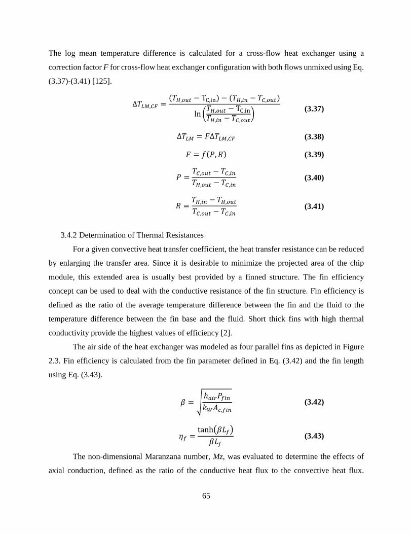
The log mean temperature difference is calculated for a cross-flow heat exchanger using a
correction factor F for cross-flow heat exchanger configuration with both flows unmixed using Eq.
(3.37)-(3.41) [125].
Δ𝛾𝛾𝐿𝐿𝑀𝑀,𝐶𝐶𝐶𝐶 =(𝛾𝛾𝐻𝐻,𝑡𝑡𝑜𝑜𝑡𝑡 − TC,in) − (𝛾𝛾𝐻𝐻,𝑎𝑎𝑖𝑖 − 𝛾𝛾𝐶𝐶,𝑡𝑡𝑜𝑜𝑡𝑡)
ln �𝛾𝛾𝐻𝐻,𝑡𝑡𝑜𝑜𝑡𝑡 − TC,in𝛾𝛾𝐻𝐻,𝑎𝑎𝑖𝑖 − 𝛾𝛾𝐶𝐶,𝑡𝑡𝑜𝑜𝑡𝑡
� (3.37)
Δ𝛾𝛾𝐿𝐿𝑀𝑀 = 𝐹𝐹Δ𝛾𝛾𝐿𝐿𝑀𝑀,𝐶𝐶𝐶𝐶 (3.38)
𝐹𝐹 = 𝑓𝑓(𝑆𝑆,𝛾𝛾) (3.39)
𝑆𝑆 =𝛾𝛾𝐶𝐶,𝑡𝑡𝑜𝑜𝑡𝑡 − 𝛾𝛾𝐶𝐶,𝑎𝑎𝑖𝑖
𝛾𝛾𝐻𝐻,𝑡𝑡𝑜𝑜𝑡𝑡 − 𝛾𝛾𝐶𝐶,𝑎𝑎𝑖𝑖 (3.40)
𝛾𝛾 =𝛾𝛾𝐻𝐻,𝑎𝑎𝑖𝑖 − 𝛾𝛾𝐻𝐻,𝑡𝑡𝑜𝑜𝑡𝑡
𝛾𝛾𝐶𝐶,𝑡𝑡𝑜𝑜𝑡𝑡 − 𝛾𝛾𝐶𝐶,𝑎𝑎𝑖𝑖 (3.41)
3.4.2 Determination of Thermal Resistances
For a given convective heat transfer coefficient, the heat transfer resistance can be reduced
by enlarging the transfer area. Since it is desirable to minimize the projected area of the chip
module, this extended area is usually best provided by a finned structure. The fin efficiency
concept can be used to deal with the conductive resistance of the fin structure. Fin efficiency is
defined as the ratio of the average temperature difference between the fin and the fluid to the
temperature difference between the fin base and the fluid. Short thick fins with high thermal
conductivity provide the highest values of efficiency [2].
The air side of the heat exchanger was modeled as four parallel fins as depicted in Figure
2.3. Fin efficiency is calculated from the fin parameter defined in Eq. (3.42) and the fin length
using Eq. (3.43).
𝛽𝛽 = �ℎ𝑎𝑎𝑎𝑎𝑎𝑎𝑆𝑆𝑟𝑟𝑎𝑎𝑖𝑖𝑘𝑘𝑊𝑊𝐴𝐴𝑐𝑐,𝑟𝑟𝑎𝑎𝑖𝑖
(3.42)
𝜂𝜂𝑟𝑟 =tanh�𝛽𝛽𝐿𝐿𝑟𝑟�
𝛽𝛽𝐿𝐿𝑟𝑟 (3.43)
The non-dimensional Maranzana number, Mz, was evaluated to determine the effects of
axial conduction, defined as the ratio of the conductive heat flux to the convective heat flux.
65

Maranzana et al. [126] stated that axial conduction can be neglected if this parameter is less than
0.01.
𝑀𝑀𝑧𝑧 =𝑘𝑘𝑤𝑤𝑘𝑘𝑟𝑟
𝐴𝐴𝑐𝑐𝐴𝐴
1RePr
(3.44)
In the current configuration the Maranzana number remains well below this threshold,
therefore axial condition was neglected. This was shown to be in good agreement with the
conjugate modeling performed using COMSOL, therefore a 1-D fin approximation is considered
appropriate.
Dittus-Boelter [127] recommend the correlation given in Eq. (3.45) for heating in a fully
developed turbulent flow in a smooth circular tube. Sieder-Tate recommend [122] a turbulent flow
correlation for flows characterized by large property variations where all properties except for
viscosity are evaluated at the mean fluid temperature given in Eq. (3.46). Sieder-Tate also
recommend a correlation for laminar flow including the effect of entry length given by Eq. (3.47).
𝑁𝑁𝜌𝜌𝐷𝐷𝑎𝑎𝑡𝑡𝑡𝑡𝑜𝑜𝑠𝑠−𝐵𝐵𝑡𝑡𝑟𝑟𝐵𝐵𝑡𝑡𝑟𝑟𝑎𝑎 = 0.023ReD0.8Pr0.4 (3.45)
𝑁𝑁𝜌𝜌𝑆𝑆𝑎𝑎𝑟𝑟𝑑𝑑𝑟𝑟𝑎𝑎−𝑇𝑇𝑎𝑎𝑡𝑡𝑟𝑟,𝑡𝑡𝑜𝑜𝑎𝑎𝑡𝑡 = 0.027ReD0.8Pr1/3 �𝜇𝜇𝜇𝜇𝑤𝑤�0.14
(3.46)
𝑁𝑁𝜌𝜌𝑆𝑆𝑎𝑎𝑟𝑟𝑑𝑑𝑟𝑟𝑎𝑎−𝑇𝑇𝑎𝑎𝑡𝑡𝑟𝑟,𝐵𝐵𝑎𝑎𝑚𝑚 = 1.86 �ReDPr𝐿𝐿/𝐷𝐷
�1/3
�𝜇𝜇𝜇𝜇𝑤𝑤�0.14
(3.47)
The air-side convection coefficient was determined using the modified-Wilson plot method
previously described. The liquid only refrigerant-side mass flow rate was adjusted while holding
the air-side mass flow rate constant and the heat loads for both fluid streams were measured. In
the modified-Wilson plot regression, the air-side Nusselt number was expected to assume the form
of the turbulent flow Sieder-Tate correlation for circular tubes given by Eq. (3.48). The refrigerant-
side was expected to assume the laminar form of the Sieder-Tate equation given by Eq. (3.49).
These forms of the Nusselt number are plugged into Eq. (3.50) to calculate the convection
coefficient and then substituted into the total thermal resistance network introduced by Eq. (3.34).
𝑁𝑁𝜌𝜌𝑎𝑎𝑎𝑎𝑎𝑎 = 𝐶𝐶𝐴𝐴Re0.8Pr13 �
𝜇𝜇𝜇𝜇𝑤𝑤�0.14
(3.48)
𝑁𝑁𝜌𝜌𝑎𝑎𝑟𝑟𝑟𝑟 = 𝐶𝐶𝑅𝑅1 �Re𝐷𝐷Pr𝐿𝐿/𝐷𝐷
�𝐶𝐶𝑅𝑅2,
�𝜇𝜇𝜇𝜇𝑤𝑤�0.14
(3.49)
66

ℎ𝑎𝑎 =𝑁𝑁𝜌𝜌𝑎𝑎𝑘𝑘𝑎𝑎𝑐𝑐𝑝𝑝,𝑎𝑎
(3.50)
The most general conceptualization of the Wilson plot method involves simultaneously
solving for three unknown constants; two correspond to the unknown functional coefficient and
the third corresponds to an unknown exponent of a flow parameter. The unknown constants do not
behave linearly and need to be found by an iterative procedure. Many procedures for carrying out
the iteration for different numbers of unknown constants have been proposed, however most
references focus on the modified-Wilson plot method proposed by Briggs and Young [123]. Their
modification to the Wilson method allows for calculation of three unknowns, the two coefficients
CA, CR1, and one exponent, CR2. However there are situations where all of the heat transfer
correlations and the wall thermal resistance are unknown. Khartabil [128] developed a method
capable of determining three resistances with up to five unknown parameters. However in order
for this method to be employed three data sets are required, each with a different dominant
resistance. In the current analysis the conducive resistance is obtained for the geometry from in
COMSOL and the assumption of scaling the Reynolds number to the power of 4/5 on the air-side
is regarded a reasonable assumption for circular channels with turbulent flow.
The equation for overall resistance was rearranged into system of equations with three unknowns
CA , CR1, and CR2 , which are constrained by Y = mX + B as given by Eq. (3.51) - (3.55) An iterative
regression is carried out for different values of the constants driven by maximization of the
coefficient of determination, R2 such that the residuals are minimized. The refrigerant-side
constant is proportional to the inverse of the slope and the air-side constant is proportional to the
inverse of the y-intercept according to the model. The results of this model were plugged into the
COMSOL model to provide a new value which was determined to be Rcnd <0.01 for all conditions
explored.
𝑌𝑌 = �1𝑈𝑈𝐴𝐴
− 𝛾𝛾𝑐𝑐𝑖𝑖𝑑𝑑� �𝑘𝑘𝐷𝐷ℎ
𝐴𝐴𝜂𝜂𝑟𝑟Re0.8Pr1 3⁄ �𝜇𝜇𝜇𝜇𝑤𝑤�0.14
�𝑎𝑎𝑎𝑎𝑎𝑎
(3.51)
𝑋𝑋 =� 𝑘𝑘𝐷𝐷ℎ
𝐴𝐴𝜂𝜂𝑟𝑟Re0.8Pr1 3⁄ � 𝜇𝜇𝜇𝜇𝑤𝑤�0.14
�𝑎𝑎𝑎𝑎𝑎𝑎
� 𝑘𝑘𝐷𝐷ℎ𝐴𝐴 � 𝜇𝜇𝜇𝜇𝑤𝑤
�0.14
�Re𝐷𝐷Pr𝐿𝐿/𝐷𝐷 �
𝐶𝐶𝑅𝑅2�𝑎𝑎𝑟𝑟𝑟𝑟
(3.52)
67

𝑚𝑚 =1𝐶𝐶𝑅𝑅1
(3.53)
𝐵𝐵 =1𝐶𝐶𝐴𝐴
(3.54)
𝑌𝑌 = 𝑚𝑚𝑋𝑋 + 𝐵𝐵 (3.55)
The air-side constant CA was calculated to be approximately 0.026 – 0.028. The air-side
constant scarcely varied as a function of the experimental conditions. The measured air-side heat
transfer coefficients for Device A and Device B are shown to be in very good agreement with the
predictions of the turbulent Sieder-Tate model as shown in Figure 3.5A. The heat transfer
coefficients are slightly under-predicted by the Dittus-Boelter equation which fails to account for
change in fluid properties of the flow. This result is in agreement with the recent findings of C.
Yang et al. [129] who concluded that conventional heat transfer correlations could be well applied
for gas flow in circular microtubes with diameters ranging from 86 – 920 μm.
The refrigerant-side heat transfer coefficients were calculated from the modified-Wilson
plot method. The refrigerant-side constants were calculated to be 1.19 –1.36 for CR1 and with 0.45
– 0.50 for CR2. On the refrigerant-side the Nusselt number predictions from these constants did not
vary significantly, as a higher computation of CR2 was compensated by lower values of CR1. The
resulting heat transfer coefficients significantly exceed the values that would be predicted by the
laminar Sieder-Tate correlations.
The calculated refrigerant-side convection coefficients are shown in Figure 3.5B compared to
Phillips [109] laminar developing flow model for flow in a rectangular channel with an aspect ratio
of 0.25 and the turbulent prediction recommended by Petukov [79]. The calculated refrigerant-
side convection coefficient are much higher than what is predicted by the theoretical models due
to the dominance of entrance effects and the transitional Reynolds numbers incurred. There is
limited data for developing flow in rectangular microchannels Phillips [109] predicts the
convection coefficients using a mathematical model. The results predicted by Phillips agree with
the numerical predictions suggested by Lee et al. [130] in a study on the effect of thermally
developing flow on heat transfer in rectangular channels having different aspect ratios.
Phillips predicts a local Nusselt number at the inlet of the channel is equal to 30,
corresponding to a convection coefficient of ~2700. Stephan et al. [131] presented correlations to
68

predict simultaneously developing flow in circular channels for constant wall heat flux and
constant wall temperature boundary conditions.
Developing flow entrance region effects for laminar flow in the short channel lengths
employed in microchannels are significant [132]. Entrance region effects become more significant
at higher Reynolds numbers, in part explaining the increasing Nusselt number trend with Reynolds
number [132]. Surface roughness effects which increase exchanger surface area and cause an early
transition to turbulence are expected to have an effect although a transition to turbulence was not
clearly indicated by the friction factor data for the refrigerant-side Reynolds number range
explored, 1000 < Reref < 2900. Kandlikar et al. [81] determined that the effect of relative roughness
on pressure drop was minimal but the heat transfer in the entry region showed a distinct
dependence on roughness. Kandlikar showed observed Nusselt number enhancements of 80 – 100%
for relative roughness ranging between 0.161 – 0.35 %. The relative roughness in the refrigerant-
side channels were not directly measured however, however it is expected that surface roughness
effects account for some of the discrepancy between the measured data and Phillips laminar model.
It is not possible to present any equations for heat transfer enhancement with roughness due to a
lack of systematic data on the devices.
For the conditions explored in this investigation, Stephan predicts Nusselt numbers ranging
74-177 for constant wall temperature boundary conditions and 17-24 for a constant heat flux
boundary condition. The wide spread between these Nusselt number ranges for the constant heat
flux and constant wall temperature boundary condition relations may elucidate the disparity
observed between Phillips laminar model and the experimental data. It is speculated that for the
higher refrigerant-side mass flow rates enhanced fluid mixing occurs. This effect may be
responsible for altering the fluid boundary at the front and back refrigerant side faces, increasing
the heat transfer. Under this condition it is possible that a constant wall temperature boundary
condition may be more suitably applied to the face of exchanger than a constant heat flux boundary
condition.
Figure 3.6 shows the thermal resistance of the heat exchanger for Device A and B as a
function of refrigerant-side mass flux for the air-side case where the upstream pressure is held at
PA =689.5 kPa. The thermal resistance is decomposed into the convective air-side and refrigerant-
side terms. The conduction resistance is not shown in the graph. It is clear that the liquid-side
refrigerant thermal resistance dominates the total thermal resistance. These results highlight the
69

directive for two-phase flow heat transfer enhancements in order to further reduce the overall
thermal resistance and increase performance.
Figure 3.5 A) Comparison of the measured air-side convection coefficients to the Sieder-Tate and Dittus-Boelter correlations. B) Comparison of the single-phase liquid refrigerant-side convection coefficients compared to Phillips laminar model and Pertukov turbulent flow model.
70

Figure 3.6 The relative contributions of the thermal resistances are given as a function of refrigerant-side mass flux for the air side condition PA =689.5 kPa.
3.4.3 Thermal Conduction Heat Transfer
The heat flow from one isothermal surface to another isothermal surface can be calculated
according to the simple relationship given in Eq. (3.56). The conduction resistance is inversely
proportional to the thermal conductivity of the material between the two surfaces. The relationship
represented by Eq. (3.57) introduces a shape coefficient, S, commonly referred to as a shape factor
in conductive heat flow. The shape factor only depends on the geometrical arrangement of the two
isothermal surfaces between which heat is transferred by conduction.
𝑄𝑄𝑐𝑐𝑖𝑖𝑑𝑑 =𝛾𝛾1 − 𝛾𝛾2𝛾𝛾𝑐𝑐𝑖𝑖𝑑𝑑
(3.56)
𝛾𝛾𝑐𝑐𝑖𝑖𝑑𝑑 =1𝑘𝑘𝑆𝑆
(3.57)
The shape factor can be determined by integration of the local heat flux over the isothermal
surfaces A1 and A2. The heat flow is given by Eq. (3.58) in which the surface normals n1 and n2
are directed into the conductive medium. The following relationship enables the shape factor to be
calculated from the known temperature field [133].
71

𝑄𝑄𝑐𝑐𝑖𝑖𝑑𝑑 = −𝑘𝑘�𝜕𝜕𝛾𝛾𝜕𝜕𝑛𝑛1
𝑑𝑑𝐴𝐴1 = 𝑘𝑘�𝜕𝜕𝛾𝛾𝜕𝜕𝑛𝑛2
𝑑𝑑𝐴𝐴2𝐴𝐴2𝐴𝐴1
(3.58)
COMSOL Multiphysics was used to calculate shape factors for the heat exchanger
geometries over the range of air-side and refrigerant-side boundary conditions explored. The
steady state temperature profile of a three-dimensional model of each heat exchanger was obtained
by application of the average temperature and heat transfer coefficients obtained from the Wilson
plot method. The top and bottom of the heat exchanger are treated as adiabatic surfaces. The heat
flow was calculated by a surface area integration over the refrigerant-side area. The shape factor
was calculated by dividing the heat flow rate, determined from the surface integration, by the
temperature difference between the surface of the refrigerant-side channel and the nearest air-side
channel. The relationship given in Eq. (3.59) reduces to Eq. (3.60) by carrying out the surface
integration over the transfer area.
𝑆𝑆 = −1
𝛾𝛾1 − 𝛾𝛾2�
𝜕𝜕𝛾𝛾𝜕𝜕𝑛𝑛1
𝑑𝑑𝐴𝐴1 =𝐴𝐴1
1𝛾𝛾1 − 𝛾𝛾2
�𝜕𝜕𝛾𝛾𝜕𝜕𝑛𝑛2
𝑑𝑑𝐴𝐴2𝐴𝐴1
(3.59)
𝑆𝑆 =𝑄𝑄
𝑘𝑘(𝛾𝛾1 − 𝛾𝛾2) (3.60)
The thermal conductivity of pure copper varies >1%, 396.9 – 393.4, over the temperature
range 20 – 80 °C. The tellurium copper alloy has a thermal conductivity of 354.6 at 20 °C, due to
a lack of readily available thermal conductivity data on this alloy, this value is assumed constant
in the analysis. The temperature dependence of the thermal conductivity could be readily
incorporated by implementation of Eq.(3.61). A function to include this effect is available in
COMSOL Multiphysics for many common materials, however this data is unavailable for the
tellurium-copper alloy used in this research.
𝑘𝑘 =1
𝛾𝛾1 − 𝛾𝛾2� 𝑘𝑘(𝛾𝛾)𝑑𝑑𝛾𝛾𝑇𝑇1
𝑇𝑇2 (3.61)
3.5 Performance Comparison
The resistance model predictions for single-phase refrigerant heating performance are
compared to the experimental data in Table 3.4. The resistance model heat rate is given using the
measured log mean temperature divided by the total thermal resistance. The modeled thermal
resistances were determined using the Sieder-Tate on the air-side and Pertukov for the refrigerant-
72

side where the Re ~ 3000. The modeled air-side friction factors were determined by the Fanno
model. The refrigerant-side friction factor was determined from the Phillips model for developing
laminar flow.
Table 3.5 compares to the resistance model predictions and the COMSOL simulation
results to the experimental results with two-phase heating condition. The simulation results were
attained by applying the experimentally obtained convection coefficients and the mean
temperature to a solid model of the device geometry COMSOL. The simulation power
performance was obtained by integrating steady state temperature profile over the heat exchanger
surface area with the given convection coefficients.
Device A Device B Model Experiment Model Experiment
Q [W] 72.3 68.8 73.0 68.8 fair 0.090 0.077 0.070 0.061 fref 0.018 0.019 0.018 0.016
Rtot [K/W] 0.71 0.73 0.67 0.71 Rair [K/W] 0.18 0.18 0.14 0.14 Rref [K/W] 0.52 0.53 0.52 0.56 Rcnd [K/W] <0.01 <0.01 <0.01 <0.01
LMTD - 50 - 48.9 Table 3.4 Table comparing modeling and experimental data for the two heat exchangers with single-phase refrigerant heating.
Table 3.5 Single-phase refrigerant heating data for Device A and Device B are compared to the expected values as calculated by the modeled thermal resistances and by the application of the experimental convection coefficients to a 3-D COMSOL model.
The heat exchanger performance for single-phase refrigerant flow is evaluated in Figure
3.7 which shows the coefficient of performance, COP, and air-side pumping power as a function
of the power dissipation of the heat exchangers. It is evident from this graph that the relative
increase in pumping power required is far larger than the power dissipation in the device. This
trend is captured by comparing the friction factor to the Colburn factor of the heat exchangers to
the Chilton-Colburn relation.
Experiment [W] Resistance Model [W] Simulation [W] Device A 68.8 70.4 72.3 Device B 68.8 73.0 69.4
73

Figure 3.7 A) COP and Pumping power as a function of power dissipation in the heat exchangers with single-phase heating. B) The experimentally obtained j vs. f curve is compared to the Chilton-Colburn relation.
74

3.6 Conclusions
Air-side pressure drops were measured in Device A and B. Well known method were
employed to reduce the data accounting for inlet, momentum, and acceleration effects in order to
produce experimentally determined friction factor data for compressible air-flow in 1 cm long
circular microchannels with hydraulic diameters of 335 and 520 μm. The experimentally obtained
data agrees with the isothermal compressible flow model to within 1%. The experimentally
obtained friction factors agree with the predictions of the adiabatic compressible Fanno flow model
within 15%. The measured friction factor for both devices are shown to decrease with increasing
Reynolds numbers. The measured friction factors for the device with the smaller hydraulic
diameter of 335 μm are less than those measured in the 520 μm channels.
Single-phase liquid refrigerant-side pressure drop for developing flow in eight parallel
rectangular copper channels having a hydraulic diameter of 0.8 mm and an aspect ratio of 0.25
were obtained. Flow development effects are shown to be relevant for 1 cm long channel. The
experimentally measured apparent friction factor was in agreement with the predictions of Phillips
[109]. Developing flow effects are relevant in determination of the pressure drop characteristics in
these devices and should be thusly incorporated into design of system when operating with single-
phase liquid only fluid flow in short rectangular microchannels
The heat transfer performance for two 1 cm3 novel heat exchangers were characterized by
application of the first law of thermodynamics to the free stream of the fluid flow in order to
calculate the total energy rate dissipated in the device. Average convection heat transfer
coefficients for air-side and single phase refrigerant-side flow were obtained using the well-known
modified-Wilson plot
The experimentally obtained air-side convection coefficients were well predicted by the
Sieder-Tate turbulent flow model. The experimentally obtained single-phase liquid refrigerant-
side convection coefficients were under-predicted by the Phillips [109] and Lee et al. [130] models
for developing flow in rectangular microchannels with an aspect ratio of 0.25. The enhancement
of the experimental results were within the range of expected enhancements resulting surface
roughness and boundary condition effects.
For the case of single-phase refrigerant-side heating, the performance enhancement of
increasing the refrigerant-side mass flux was more pronounced than adjustments to the air-side
due to the dominance in refrigerant-side thermal resistance. The air-side and refrigerant-side
75

convection coefficients were similar however the ratio of the air side transfer area to the
refrigerant-side transfer area 3 and 3.33 for Device A and B respectively.
76

CHAPTER 4: PHASE CHANGE PERFORMANCE
4.1 Overview
The heat transfer performance of the heat exchangers is evaluated by application of the first
law of thermodynamics to the free stream of the fluid flow in order to calculate the total energy
between the upstream and downstream positions. The next step in the thermal characterization is
to obtain average convection heat transfer coefficients for air-side and refrigerant-side flow in the
device. The obtained experimental results are used to characterize deviations from the predictions
of conventional theory.
Two-phase refrigerant-side pressure drops were measured for the case of R245fa
condensing at 80 °C in rectangular minichannels in Device A and Device B. The experimental
results were compared to the conventional correlations recommended by Friedel. Given the short
channel lengths and very small pressure drops incurred it was determined that these models were
adequate for the purpose of designing heat exchanger systems with short lengths. It is emphasized
that the additional pressure drop effects due to changes in momentum of the condensing liquid,
contraction at the inlet, and expansion at the exit are of equal relevance and should be accounted
for. It is recommended that these effects be accounted for in determination of two-phase
condensation pressure drop when designing heat exchangers with short channel lengths.
The overall heat transfer performance for two 1 cm3 heat exchangers were compared for a
range of operating conditions. Comparison with the literature for heat transfer in compact heat
exchangers show that these results were reasonably predicted through utilization of the
conventional theory. The experimentally obtained two-phase refrigerant-side convection
coefficient were within the expected range predicted by the Akers model.
4.2 Condensation Refrigerant-Side Pressure Drop
The frictional pressure drop for two-phase flow in microchannels is generally determined
using the macroscale correlations recommended by Lockhart Martinelli [134] and Friedel [94].
There have been a number of correlations based on modifications to these models [86, 135]. Friedel
developed a correlation based on a database of 25,000 points for adiabatic flow through channels
1 mm in diameter or larger. The correlation uses a liquid-only Reynolds number, ReL O, Eq. (4.1),
77

to find liquid-only friction factors, fLO, Eq. (4.2) and a vapor-only Reynolds number, ReLO, Eq.
(4.3) to find a vapor-only friction factor, fVO , given by Eq. (4.4).
The two-phase pressure drop given by Eq. (4.5) is expressed in terms of a liquid only two-
phase multiplier corresponding to single-phase liquid as given by Eq.(4.6)-(4.8). The two-phase
multiplier is a function of the liquid-only and vapor-only density, viscosity, Weber number and
Froude number.
The Weber number is the dimensionless ratio of the fluids inertia to its surface tension
defined by Eq. (4.9). The Froude number is the dimensionless ratio of the characteristic fluid
velocity to gravitational forces as defined by Eq. (4.10). The two-phase mixture density is
calculated by Eq. (4.11).
ReLO =𝐺𝐺𝐷𝐷ℎ𝜇𝜇𝐵𝐵
(4.1)
𝑓𝑓𝐿𝐿𝐿𝐿 = 0.079𝛾𝛾𝜕𝜕−0.25 (4.2)
ReVO =𝐺𝐺𝐷𝐷ℎ𝜇𝜇𝑣𝑣
(4.3)
𝑓𝑓𝑉𝑉𝐿𝐿 = 0.079𝛾𝛾𝜕𝜕−0.25 (4.4)
�−𝑑𝑑𝑆𝑆𝐷𝐷𝑧𝑧� = 𝜙𝜙𝐿𝐿𝐿𝐿2 �
2𝑓𝑓𝐿𝐿𝐿𝐿𝐺𝐺2
𝜌𝜌𝐵𝐵𝐷𝐷ℎ� (4.5)
𝜙𝜙𝐿𝐿𝐿𝐿2 = 𝐶𝐶1 +3.24𝐶𝐶2
𝐹𝐹𝑟𝑟0.045𝑊𝑊𝜕𝜕0.035 (4.6)
𝐶𝐶1 = (1 − 𝑥𝑥)2 + 𝑥𝑥2 �𝜌𝜌𝐵𝐵𝑓𝑓𝑉𝑉𝐿𝐿𝜌𝜌𝑣𝑣𝑓𝑓𝑉𝑉𝐿𝐿
� (4.7)
𝐶𝐶2 = 𝑥𝑥0.78(1 − 𝑥𝑥)0.24 ��𝜌𝜌𝐵𝐵𝜌𝜌𝑣𝑣�0.91
�𝜇𝜇𝐵𝐵𝜇𝜇𝑣𝑣�0.19
�1 − 𝜇𝜇𝑣𝑣𝜇𝜇𝐵𝐵
�0.7
� (4.8)
𝑊𝑊𝜕𝜕 =𝐺𝐺2𝐷𝐷ℎ𝜌𝜌𝑡𝑡𝑝𝑝𝜎𝜎
(4.9)
𝐹𝐹𝑟𝑟 =𝐺𝐺2
𝑔𝑔𝐷𝐷ℎ𝜌𝜌𝑡𝑡𝑝𝑝 (4.10)
78

The measured pressure drop includes additional losses at the channel entrance and exit, as
well as changes in the acceleration. These effects must to be accounted for in order to compare the
experimentally determined pressure drop to the predictions of the models. The measured pressure
drop for two-phase flow is given by Eq. (4.12). The equation accounts for the effects of contraction
at the inlet, expansion at the exit, frictional pressure loss in the core, and momentum changes
caused by the changing vapor fraction as condensation takes place along the channel.
Δ𝑆𝑆𝑚𝑚𝑟𝑟𝑎𝑎𝑠𝑠 = Δ𝑆𝑆𝑟𝑟𝑖𝑖𝑡𝑡 + Δ𝑆𝑆𝑟𝑟𝑎𝑎𝑎𝑎𝑐𝑐 + Δ𝑆𝑆𝑚𝑚𝑡𝑡𝑚𝑚 + Δ𝑆𝑆𝑟𝑟𝑒𝑒𝑎𝑎𝑡𝑡 (4.12)
Hewitt et al. [136] recommend a homogenous flow model to account for contraction effects
at the entrance using Eq. (4.13), where CC is the coefficient of contraction given by Eq. (4.14)
[137].
Δ𝑆𝑆𝑟𝑟𝑖𝑖𝑡𝑡 =G2
2𝜌𝜌𝑟𝑟��
1𝐶𝐶𝑐𝑐− 1�
2
+ 1 − 𝜎𝜎2� �1 + 𝑥𝑥 �𝜌𝜌𝑟𝑟𝜌𝜌𝑓𝑓
− 1�� (4.13)
Cc =1
0.639(1 − 𝜎𝜎)0.5 + 1 (4.14)
𝜌𝜌𝑇𝑇𝑃𝑃 = �𝑥𝑥𝜌𝜌𝑣𝑣
+1 − 𝑥𝑥𝜌𝜌𝐵𝐵
�−1
(4.11)
79

Figure 4.1 Two-phase Refrigerant-side pressure drop measurements for Device A and B compared to the frictional of pressure drop predictions of the Friedel model, along with the pressure drop effects due to acceleration effects, expansion effects, and contraction effects.
Hewitt et al. recommend a separated flow model to account for the expansion effects at the
exit using Eq. (4.15) where ψS, is the separated flow multiplier given by Eq. (4.16).
Δ𝑆𝑆𝑟𝑟𝑒𝑒𝑎𝑎𝑡𝑡 =𝐺𝐺2𝜎𝜎(1 − 𝜎𝜎)𝜓𝜓𝑆𝑆
𝜌𝜌𝑟𝑟 (4.15)
𝜓𝜓𝑆𝑆 = 1 + �𝜌𝜌𝑟𝑟𝜌𝜌𝑓𝑓
− 1� [0.25𝑥𝑥(1 − 𝑥𝑥) + 𝑥𝑥2] (4.16)
Carey [138] recommends Eq. (4.17) to account for the pressure drop due to momentum
changes as the fluid decelerates due to the change in quality where α is the void fraction given by
Eq. (4.18). The void fraction is the ratio of the cross sectional area occupied by the gas relative to
the total cross sectional area of the channel. The calculation of this parameter is considered
essential to predicting the pressure drop in two-phase flow and various models have been proposed
to evaluate this parameter in the literature [43].
80

ΔP𝑚𝑚𝑡𝑡𝑚𝑚 = �𝐺𝐺2𝑥𝑥2
𝜌𝜌𝑓𝑓𝛼𝛼+𝐺𝐺2(1 − 𝑥𝑥)2
𝜌𝜌𝑟𝑟(1 − 𝛼𝛼) �𝑒𝑒=𝑒𝑒𝑚𝑚𝑜𝑜𝑒𝑒
− �𝐺𝐺2𝑥𝑥2
𝜌𝜌𝑓𝑓𝛼𝛼+𝐺𝐺2(1 − 𝑥𝑥)2
𝜌𝜌𝑟𝑟(1 − 𝛼𝛼) �𝑒𝑒=𝑒𝑒𝑖𝑖𝑒𝑒
(4.17)
𝛼𝛼 =𝐴𝐴𝑣𝑣𝐴𝐴
(4.18)
Figure 4.1B depicts the measured pressure drop for Device A and Device B for the case of
of R245fa condensing at 80 °C. After entrance, exit, and momentum effects are accounted for, the
experimental pressure drop agrees with the predictions of both the Friedel and Lockhart Martinelli.
A study accounting for the quality at the inlet and exit would be required to provide a more
thorough investigation on this subject. These models are appropriate for the intent of designing
heat exchanger systems at this scale where the channel length is very short where ancillary effects
due to momentum, contraction, and expansion are on the order of relevance as the frictional
pressure drop.
4.3 Heat Exchanger Performance
Energy is transferred in the exchanger from the condensing refrigerant to the air flow. The
energy transferred between the two fluids in the heat exchanger is evaluated considering the
reduction of the energy equation for the air-side fluid stream. The change in energy between any
two points in the air flow can be calculated by Eq. (4.19) assuming a steady, compressible flow,
with negligible potential energy change, and negligible external volume forces [34].
𝑄𝑄𝑎𝑎𝑎𝑎𝑎𝑎 = 𝑐𝑐𝑝𝑝,𝑎𝑎𝑎𝑎𝑎𝑎(𝛾𝛾0,𝑡𝑡𝑜𝑜𝑡𝑡 − 𝛾𝛾0,𝑎𝑎𝑖𝑖) (4.19)
An energy balance on the heat exchanger is satisfied for a control volume including the
cross flow heat exchanger assuming the exchanger is well insulated, there is no heat loss to the
surroundings by the equality given in Eq. (4.20).
𝑄𝑄𝑎𝑎𝑎𝑎𝑎𝑎 = 𝑄𝑄𝑎𝑎𝑟𝑟𝑟𝑟 (4.20)
Figure 4.2 shows the measured performance for the 1 cm3 heat exchanger devices for two-
phase refrigerant flow as a function of air-side Reynolds number. Device A and B are characterized
at saturation temperatures of 80 °C with and a refrigerant-side mass flux of 750 kg/m2-s. The heat
exchangers’ power density performance increased as a function of the air-side Reynolds number.
81

For Device A and Device B heat rates of 114 – 152 W and 127 – 179 W were achieved for the
respective Reynolds number ranges 9000 – 20,000 and 8000 – 13,500 and in-tube refrigerant-side
condensation at a saturation temperature of 80 °C. The additional performance enhancement of
increasing the refrigerant-side mass flux was observed but not reported due to the investigations
focus on high performance results. The thermal conductance for Device A and Device B are shown
in Figure 4.3 for the same range of parameter operation described. A total thermal conductance of
3.3 K/W and 3.7 K/W are achieved for Device A and B respectively for the highest air-side flow
rate tested.
Figure 4.2 Heat rate power performance of Device A and Device B with two-phase refrigerant side heating at a mass flux of 750 kg/m2-s as a function of air-side Re.
82

Figure 4.3 Thermal conductance of Device A and Device B as a function of air-side Re.
4.3.1 Two-Phase Condensation
The heat rate was experimentally determined from the thermodynamic energy balance
between the upstream and downstream air-side flow which was carried out and validated during
single-phase liquid flow of the refrigerant. Evaluation of the experimental heat rate and log-mean
temperature difference gave the overall heat transfer coefficient and the overall thermal resistance.
Characterization of the single-phase performance yielded air-side convection coefficients in to be
agreement with the Sieder-Tate correlation. The air-side convective resistance and conduction
resistance were determined using the result from Sieder-Tate and COMSOL models respectively.
The refrigerant-side resistance was determined Eq. (4.21) which was used to calculate the
refrigerant-side convection coefficient with Eq. (4.22).
𝛾𝛾𝑎𝑎𝑟𝑟𝑟𝑟,𝑇𝑇𝑃𝑃 = 𝛾𝛾𝑡𝑡𝑡𝑡𝑡𝑡 − 𝛾𝛾𝑎𝑎𝑎𝑎𝑎𝑎 − 𝛾𝛾𝑐𝑐𝑖𝑖𝑑𝑑 (4.21)
ℎ𝑎𝑎𝑟𝑟𝑟𝑟 =1
𝛾𝛾𝑎𝑎𝑟𝑟𝑟𝑟𝐴𝐴𝑎𝑎𝑟𝑟𝑟𝑟 (4.22)
83

Akers defines an equivalent mass flux, Eq. (4.23), to express an equivalent Reynolds
number given by Eq. (4.24). The Akers Nusselt number correlation for Ree < 50,000 is given by
Eq. (4.25), where Prl is the liquid-only Prandtl number.
𝐺𝐺𝑟𝑟 = 𝐺𝐺 �(1 − 𝑥𝑥) + 𝑥𝑥 �𝜌𝜌𝐵𝐵𝜌𝜌𝑣𝑣�0.5� (4.23)
Ree =𝐺𝐺𝑟𝑟𝐷𝐷ℎ𝜇𝜇𝐵𝐵
(4.24)
𝑁𝑁𝜌𝜌𝐴𝐴𝐴𝐴𝑟𝑟𝑎𝑎𝑠𝑠 = 5.03𝛾𝛾𝜕𝜕𝑟𝑟1/3Pr𝐵𝐵
1/3 (4.25)
Figure 4.4 compares the experimentally derived refrigerant-side convection coefficients
those obtained from the Akers model. The Akers model predictions are a strong function of
refrigerant vapor quality. The vapor-only maximum and the liquid-only minimum limits of the
model are shown as limits of the prediction. Since the vapor refrigerant quality was not accounted
for in the experiment there is not an explicit way to compare the model to the experimental data.
As evidenced in the figure, the convection coefficients are within the range of what the Akers
model predicts for the possible range of refrigerant vapor quality.
Figure 4.5 shows the total thermal resistance is decomposed into constitutive terms
accounting for air-side convective resistance, refrigerant- side convective resistance and the
conduction resistance of the exchanger. The thermal resistance on the air-side is slightly higher
than the thermal resistance on the refrigerant side but the two thermal resistances are well matched
as intended by the design for two-phase flow.
There have been few studies on measurement of heat transfer that address Dh < 1 mm.
Yang and Webb [139] found the Akers correlation better predicted their results than the Shah
correlation. The heat transfer coefficient in their work showed a heat flux dependence h ~ Q”0.2.
Heat flux dependence is typically only observed in stratified flows that only occur at very low
mass fluxes. It was reasoned that the observed dependence of the heat transfer coefficient on heat
flux was due to the momentum contribution [140]. Wang et al. [141] investigated condensation of
R134a in 10 multiport 610-mm long rectangular channels with a hydraulic diameter of 1.46 mm
(1.5 mm x 1.4 mm) over the mass flux range 75-750 kg/m2-s. The study reports strong heat transfer
coefficient dependence on quality at high mass fluxes, a sign of annual flow conditions. Of the
available heat transfer correlations their data agree best with the Akers model. The study also
84

suggests that the rectangular corners aided in the formation of annular flow, and an earlier
transition to annular flow was observed than expected with the Soliman map [43].
Cooling of superheated vapors involves condensation when the wall temperature is below
the saturation temperature of the vapor. If the wall temperature is below the saturation temperature,
then condensation of the superheated vapor will occur in the thermal boundary layer on the tube
wall, even though the bulk vapor is superheated. Since the condensing heat transfer is much more
effective than single-phase heat transfer to a vapor it is important to include the effect of the de-
superheating zone with respect to the saturated condensing zone. The saturated zone method is
usually evaluated at a vapor quality of 0.99. This scenario illustrates the dependence on the process
path the system follows to reach its operating state. If the hot refrigerant is applied to the already
cooled heat exchanger the de-superheating zone is found using the condensing heat transfer
coefficient in the thermal resistance analysis rather than the single-phase heat transfer coefficient
of the vapor phase [91].
Figure 4.4 Experimentally reduced refrigerant-side convection coefficients as a function of the heat flux compared to the Akers model for a refrigerant quality of x=1 and x=0.
85
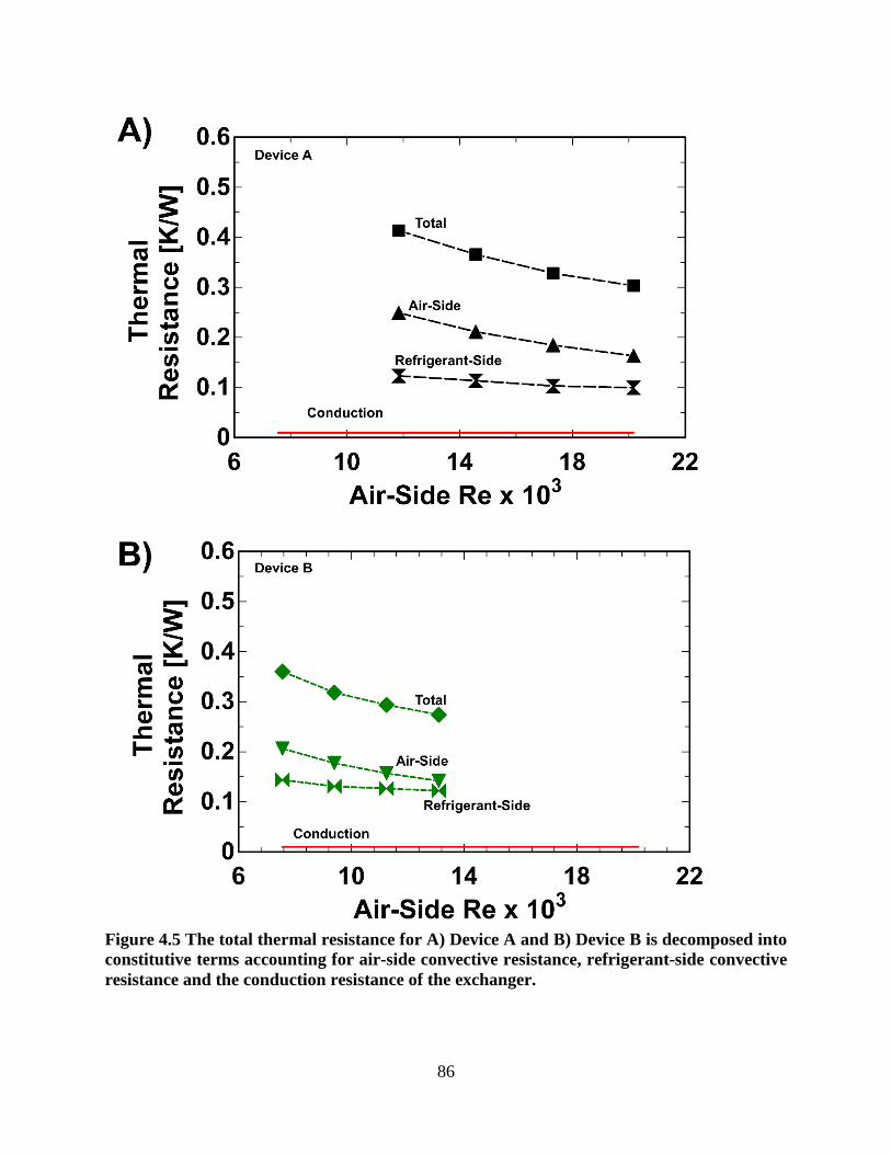
Figure 4.5 The total thermal resistance for A) Device A and B) Device B is decomposed into constitutive terms accounting for air-side convective resistance, refrigerant-side convective resistance and the conduction resistance of the exchanger.
86

4.3.2 Thermal Conduction Heat Transfer
The heat flow from one isothermal surface to another isothermal surface can be calculated
according to the simple relationship given in Eq. (4.26). The conduction resistance is inversely
proportional to the thermal conductivity of the material between the two surfaces. The relationship
represented by Eq. (4.27) introduces a shape coefficient, S, commonly referred to as a shape factor
in conductive heat flow. The shape factor only depends on the geometrical arrangement of the two
isothermal surfaces between which heat is transferred by conduction.
𝑄𝑄𝑐𝑐𝑖𝑖𝑑𝑑 =𝛾𝛾1 − 𝛾𝛾2𝛾𝛾𝑐𝑐𝑖𝑖𝑑𝑑
(4.26)
𝛾𝛾𝑐𝑐𝑖𝑖𝑑𝑑 =1𝑘𝑘𝑆𝑆
(4.27)
The shape factor can be determined by integration of the local heat flux over the isothermal
surfaces A1 and A2. The heat flow is given by Eq. (4.28) in which the surface normals n1 and n2
are directed into the conductive medium. The following relationship enables the shape factor to be
calculated from the known temperature field [133].
𝑄𝑄𝑐𝑐𝑖𝑖𝑑𝑑 = −𝑘𝑘�𝜕𝜕𝛾𝛾𝜕𝜕𝑛𝑛1
𝑑𝑑𝐴𝐴1 = 𝑘𝑘�𝜕𝜕𝛾𝛾𝜕𝜕𝑛𝑛2
𝑑𝑑𝐴𝐴2𝐴𝐴2𝐴𝐴1
(4.28)
COMSOL Multiphysics was used to calculate shape factors for the heat exchanger
geometries over the range of air-side and refrigerant-side boundary conditions explored. The
steady state temperature profile of a three-dimensional model of each heat exchanger was obtained
by application of the average temperature and heat transfer coefficients obtained from the Wilson
plot method. The top and bottom of the heat exchanger are treated as adiabatic surfaces. The heat
flow was calculated by a surface area integration over the refrigerant-side area. The shape factor
was calculated by dividing the heat flow rate, determined from the surface integration, by the
temperature difference between the surface of the refrigerant-side channel and the nearest air-side
channel. The relationship given in Eq. (4.29) reduces to Eq. (4.30) by carrying out the surface
integration over the transfer area.
𝑆𝑆 = −1
𝛾𝛾1 − 𝛾𝛾2�
𝜕𝜕𝛾𝛾𝜕𝜕𝑛𝑛1
𝑑𝑑𝐴𝐴1 =𝐴𝐴1
1𝛾𝛾1 − 𝛾𝛾2
�𝜕𝜕𝛾𝛾𝜕𝜕𝑛𝑛2
𝑑𝑑𝐴𝐴2𝐴𝐴1
(4.29)
𝑆𝑆 =𝑄𝑄
𝑘𝑘(𝛾𝛾1 − 𝛾𝛾2) (4.30)
87
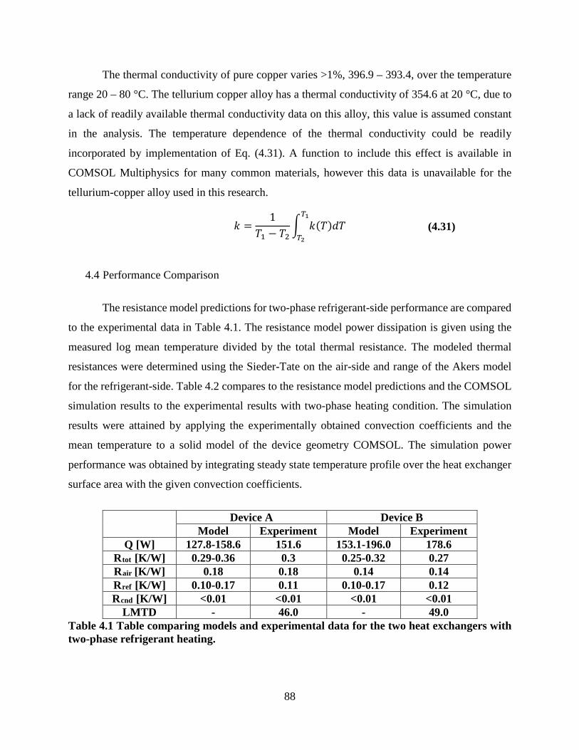
The thermal conductivity of pure copper varies >1%, 396.9 – 393.4, over the temperature
range 20 – 80 °C. The tellurium copper alloy has a thermal conductivity of 354.6 at 20 °C, due to
a lack of readily available thermal conductivity data on this alloy, this value is assumed constant
in the analysis. The temperature dependence of the thermal conductivity could be readily
incorporated by implementation of Eq. (4.31). A function to include this effect is available in
COMSOL Multiphysics for many common materials, however this data is unavailable for the
tellurium-copper alloy used in this research.
𝑘𝑘 =1
𝛾𝛾1 − 𝛾𝛾2� 𝑘𝑘(𝛾𝛾)𝑑𝑑𝛾𝛾𝑇𝑇1
𝑇𝑇2 (4.31)
4.4 Performance Comparison
The resistance model predictions for two-phase refrigerant-side performance are compared
to the experimental data in Table 4.1. The resistance model power dissipation is given using the
measured log mean temperature divided by the total thermal resistance. The modeled thermal
resistances were determined using the Sieder-Tate on the air-side and range of the Akers model
for the refrigerant-side. Table 4.2 compares to the resistance model predictions and the COMSOL
simulation results to the experimental results with two-phase heating condition. The simulation
results were attained by applying the experimentally obtained convection coefficients and the
mean temperature to a solid model of the device geometry COMSOL. The simulation power
performance was obtained by integrating steady state temperature profile over the heat exchanger
surface area with the given convection coefficients.
Device A Device B Model Experiment Model Experiment
Q [W] 127.8-158.6 151.6 153.1-196.0 178.6 Rtot [K/W] 0.29-0.36 0.3 0.25-0.32 0.27 Rair [K/W] 0.18 0.18 0.14 0.14 Rref [K/W] 0.10-0.17 0.11 0.10-0.17 0.12 Rcnd [K/W] <0.01 <0.01 <0.01 <0.01
LMTD - 46.0 - 49.0 Table 4.1 Table comparing models and experimental data for the two heat exchangers with two-phase refrigerant heating.
88

Table 4.2 Two-phase refrigerant heating data for Device A and Device B are compared to the expected values as calculated by the modeled thermal resistances and by the application of the experimental convection coefficients to a 3-D COMSOL model.
4.5 Conclusions
Two-phase refrigerant-side pressure drops were measured for the case of R245fa
condensing at 80 °C in rectangular minichannels in Device A and Device B. The experimental
results were compared to the conventional correlations recommended by Friedel. Given the short
channel lengths and very small pressure drops incurred it was determined that these models were
adequate for the purpose of designing heat exchanger systems with short lengths. It is emphasized
that the additional pressure drop effects due to changes in momentum of the condensing liquid,
contraction at the inlet, and expansion at the exit are on the same order of relevance as the frictional
pressure drop effect. It is recommended that these effects be accounted for in determination of
two-phase condensation pressure drop when designing heat exchangers employing short channel
lengths.
The friction factors on the air-side were the same for the case of single-phase and two-
phase refrigerant-side heating. The measured friction factors for the device with the smaller
hydraulic diameter of 335 μm are less than those measured in the 520 μm channels.
The heat transfer performance for two 1 cm3 novel heat exchangers were characterized by
application of the first law of thermodynamics to the free stream of the air flow in order to calculate
the total energy rate dissipated in the device. Average convection heat transfer coefficients for air-
side and single phase refrigerant-side flow were obtained using the well-known modified-Wilson
plot method. An average two-phase convection coefficient on the refrigerant-side with
condensation phase change was obtained and found to be in agreement with the results of Akers
condensation model.
The overall heat transfer performance for two 1 cm3 heat exchangers were compared for a
range of operating conditions. Comparison with the literature for heat transfer in compact heat
exchangers show that these results were reasonably predicted through utilization of the
conventional theory. The experimentally obtained two-phase refrigerant-side convection
Experiment [W] Resistance Model [W] Simulation [W] Device A 151.6 127.8-158.6 152.5 Device B 178.6 153.1-196.0 186.8
89

coefficient were within the expected range predicted by the Akers model for qualities between 0
and 1.
Experimental techniques in the design of compact micro-heat exchangers are validated for
designing compact heat exchangers with high power density performance. For the case of two-
phase refrigerant-side heating, the adjustments to the air-side were more pronounced than in the
single-phase case and the air-side and refrigerant-side thermal resistances were well matched.
Total thermal resistances of 0.3 K/W and 0.27 K/W for the 1 cm3 heat exchangers are reported.
90

CHAPTER 5: SCALING OF METHODOLOGY
Figure 5.1 shows photographs of Device C which comprises 600 circular air-side
microchannels with an average microchannel diameter of 482 μm configured into a high-density
honeycomb array with an average center-to-center offset pitch spacing of 671 μm. Device C has
14 refrigeration channels configured into two rows of 7 horizontal rectangular minichannels with
a cross sectional aspect ratio of 0.5 x 2 mm separated by 0.5 mm center-to-center pitch offset. The
air side and refrigerant side characteristics are summarized in Table 5.1 Device C has a surface
area to volume ratio of 2111 m2/m3 and an air-side aspect ratio of 41.5.
Figure 5.1 A) Isometric photograph of 10 cm3 heat exchanger, Device C. Microscope images of B) Air-side and C) refrigerant-side are shown.
91

Device C
Air-Side
Dh 482 μm NT 600 A 189.65 cm2 Ac 109 mm2
L/Dh 41.5
Refrigerant-side
Dh 800 μm NT 14 A 12.43 cm2 Ac 14.0 mm2
L/Dh 28.125 Table 5.1 Summary of the air-side and refrigerant-side characteristics of 10 cm3 manufactured heat exchangers.
The performance of Device C is simulated in COMSOL as shown for the range of expected
boundary conditions based on the experimental investigation of the two 1 cm3 devices. Scaling of
these techniques were applied to a 10 cm3 heat exchanger. A power performance of 1 kW and a
power density performance of 100 W/cm3 with an overall thermal resistance < 0.05 are achievable.
The expected performance of the device with two-phase refrigerant-side flow at a saturation
temperature of 80 °C and an average air-side temperature of 37 °C are shown for the for air-side
convection coefficients 1000 – 4000 W/m2-K and refrigerant-side convection coefficients 10,000
– 16,000 W/m2-K.
92

Figure 5.2 Simulated power density power dissipation and overall thermal resistance for the range of expected air-side and refrigerant-side boundary conditions.
93

CHAPTER 6: CONCLUSIONS
6.1 Significance of Work
The current investigation demonstrates the design, fabrication, and characterization of
ultra-compact air-cooled condenser heat exchangers with exceptional power density performance
of up to 180 W/cm3, exceeding the program goal of 100 W/cm3. This exceptional heat exchanger
performance is attributed to the implementation of high-speed compressible air flow in circular
microchannels and two-phase condensation flow of a refrigerant in rectangular minichannels to
achieve high heat transfer performance in a compact design. The heat exchangers are air-cooled
with air speeds and flow rates that are in a relatively unexplored range for power electronics
cooling. High-speed turbulent flow is explored in parallel copper microchannels. The heat
exchangers utilize dielectric refrigerant as the heat transfer working fluid. Performance results are
obtained with single-phase liquid phase and phase change condensation of refrigerant R245fa.
Phase change is induced at desirable temperatures and reasonable pressures. These advancements
are enabled by recent developments in micro-electric discharge machining to produce very high
surface area compact heat exchanger devices.
Air-cooled heat sinks have been identified as pivotal to the future of thermal management
of microelectronics in the 21st century. Air-cooling systems provide clear advantages in overall
ease of integration due to its availability and abundance over forced liquid cooling systems. The
enhancement of forced air flow is especially important because it generally represents the
dominant thermal resistance of the condenser. The implementation of high-speed compressible air
flow in microchannels permits investigation of flow conditions with exceptionally high heat
transfer coefficients. This investigation explores turbulent flow regime conditions for air-side
Reynolds numbers 8,000 < Re < 20,000, in high-density parallel arrangements of 1 cm long
circular copper microchannels, 355 and 520 μm in diameter.
Two-phase heat transfer technology is one of the most efficient methods of waste heat
removal in high power electronics cooling. It is especially advantageous in applications where size,
weight, and efficiency are important factors. Two-phase active cooling systems consist of an
evaporator and a condenser. Heat transfer performance in the evaporator is typically much higher
than in the condenser; consequently the condenser is the limiting component of the entire cooling
system. Improvements in condenser technology enable electronics systems to operate at a higher
94

power while reducing the overall cooling system size and weight. The condensation phase change
process in microchannels with high aspect ratios yields the formation of a thin film condensation
layer on the heat transfer wall, resulting in high heat transfer coefficients with little pressure drop
penalty. It is therefore of utmost importance that condensation phenomena, especially in high
aspect-ratio microchannels be experimentally investigated. This investigation employs
condensation in a parallel array of high-aspect ratio, 0.5 mm x 2 mm, rectangular minichannels.
Compact heat exchangers are manufactured using novel micro-electro-discharge
machining to produce high-density, high aspect ratio microchannels in a copper alloy. The heat
exchanger performance is characterized for single-phase liquid and phase-change condensation of
a refrigerant. The heat exchangers are operated using single-phase liquid flow of dielectric
refrigerant R245fa at 80 °C and high-speed flow of air at ~25 °C to demonstrate a power density
performance of nearly 70 W/cm3. The heat exchangers are operated using two-phase condensation
of R245fa at 80 °C and high-speed flow of air at ~25 °C to achieve power density performance >
175 W/cm3 and overall thermal resistance < 0.27 K/W.
Test methodologies were implemented for determination of the thermal-hydraulic
performance of these novel devices. Modeling and characterization of this system were
implemented using well-known methods and the results are compared with the corresponding
literature for microchannel fluid flow and heat transfer. The results of this work are compared to
the state of the art of air-cooled heat exchangers. The Sandia cooler reports performance with a
normalized volume of ~0.3, and a thermal resistance of ~0.15 K/W [22]. Published experimental
results on the PHUMP which employs an impeller motor to cool a single condenser loop heat pipe
with a condenser 26 cm3 (10.2 x 10.2 x 0.25 cm) in size, dissipated a heat load of 200 W, (a power
density of 7 W/cm3) and an overall thermal resistance of 0.177 K/W [25]. The study of this system
demonstrates an advancement in the known state-of-the-art in power density performance of
compact air-cooled heat sinks. Power dissipation rates > 1 kW and an overall thermal resistance
of < 0.05 K/W are projected with scaling of these methodologies in a 10 cm3 device.
This work provides direct understanding and validation of test methodologies and
characterization techniques for applications of these previously unexplored operating conditions
for the application of electronics cooling. The results have generality and impart value beyond the
immediate application in industries ranging from military, power electronics, power energy,
automotive, HVAC, cryogenics, and MEMS. The modeling and characterization techniques
95

employed were validated for microchannel geometries where the continuum assumption remains
valid down to 10 μm channel diameter.
6.2 Conclusions
The design and manufacturing for μEDM manufactured copper compact heat exchangers
are presented. Experimental design for air side and refrigerant side test facilities utilized to
characterize the compact heat exchangers are described. Experimental procedures for single-phase
and two-phase refrigerant heating over a range of operating conditions are detailed. The
experimental methodology including measurement strategy and uncertainty analysis is discussed.
Air-side pressure drops were measured in Device A and B. Well known methods were
employed to reduce the data accounting for inlet, momentum, and acceleration effects in order to
produce experimentally determined friction factor data for compressible air-flow in 1 cm long
circular microchannels with hydraulic diameters of 335 and 520 μm. The experimentally obtained
data agrees with the isothermal compressible flow calculation to within 1%. The experimentally
obtained friction factors agree with the predictions of the adiabatic compressible Fanno flow model
within 15%. The measured friction factor for both devices are shown to decrease with increasing
Reynolds numbers. The measured friction factors for the device with the smaller hydraulic
diameter of 335 μm are less than those measured in the 520 μm channels.
Single-phase liquid refrigerant-side pressure drop for developing flow in eight parallel
rectangular copper channels having a hydraulic diameter of 0.8 mm and an aspect ratio of 0.25
were obtained. Flow development effects are shown to be relevant for 1 cm long channel. The
experimentally measured apparent friction factor was in agreement with the predictions of Phillips
[109]. Developing flow effects are relevant in determination of the pressure drop characteristics in
these devices and should be thusly incorporated into design of system when operating with single-
phase liquid only fluid flow in short rectangular microchannels. The pressure drop of single-phase
liquid flow in rectangular channels are described by developing laminar flow in rectangular
channels once entrance and exit effects were accounted for.
The conversion of thermal energy to kinetic energy by the expanding gas is relevant and
must be accounted for in the air-side energy balance. Heat transfer performance of high-speed air
flow with Re > 20,000 in circular microchannels were accurately predicted by the Sieder-Tate
correlation. Developing flow effects dominate single-phase liquid heat transfer in rectangular
96

microchannels and should be accounted for in the design phase. The surface roughness effects and
boundary conditions at the front and rear faces of the heat exchanger are thought to enhance the
overall entrance effects for the transitional Reynolds numbers explored.
The experimental condensation heat transfer coefficients were within the bounds predicted by
Akers model. The two-phase pressure drop was within the range predicted by both the Friedel
model once entrance, exit, and momentum pressure drop effects were accounted for. The losses
due to contraction, expansion, and momentum of the condensing fluid are equally relevant to the
frictional loss in 1 cm long rectangular passages and should be incorporated at the design stage for
predicting the total pressure drop.
6.3 Recommendations for Future Work
Research focused on scaling these methodologies to achieve 1 kW of power dissipation at
a power density of 100 W/cm3 is underway and is expected to be achieved through in Device C
introduced in Figure 5.1. Further advances beyond this can be realized by creating shorter air-side
fins for the heat exchanger by the addition of more rows of refrigerant-side channels.
Given the volatility of the refrigerant-side heat transfer coefficient as a function of quality,
methods to regulate the saturation conditions for optimal performance are recommended.
Techniques for adjusting the saturation conditions, such as the use of an electrical heater attached
to the surface of a liquid reservoir regulated by a PID controller to stabilize the pressure may be
employed as a means of stabilizing the saturation conditions to optimize device performance [84].
By stabilizing the saturation conditions and accounting for the quality changes of the refrigerant,
a deeper understanding of the phase change characteristics of the refrigerant can be realized.
Modeling cross-flow heat exchangers with additional cross channels show increased heat
transfer performance. The validation of the models demonstrated by this research provide for the
engineering design of producing similar compact heat exchangers with improved power density
performance and a reduced overall thermal resistance. The heat exchangers employed in this work
can be optimized by integration of more refrigerant-side channels and by utilization of the top and
bottom surfaces of the devices in heat exchange.
The opportunity of placing several heat exchangers in series with new air being injected
into the flow stream promise viability for scaling of these techniques to accommodate higher heat
loads. While the temperature of the air flow increases due to heat transfer it simultaneously cools
97

as it expands along the flow length. Demonstrations of these types of optimization techniques
where new fluid is injected into the stream have already being employed to improve efficiency of
next generation power plants and in the production of hydrogen. Future research towards the
integration of employing multiple heat exchangers in parallel and serial configurations is
recommended.
98

REFERENCES
[1] D.B. Tuckerman, R.F.W. Pease, High-performance heat sinking for VLSI, Electron device
letters, 2 (1981) 126-129.
[2] A. Bar-Cohen, Thermal Management of Air- and Liquid-Cooled Multichip Modules, Ieee
Transactions on Components Hybrids and Manufacturing Technology, 10 (1987) 159-175.
[3] F.P. Incropera, Convection Heat Transfer in Electronic Equipment Cooling, Journal of heat
transfer, 110 (1989) 1097111.
[4] M. Khan, A. Fartaj, A review on microchannel heat exchangers and potential applications,
International journal of energy research, 35 (2011) 553-582.
[5] M. Baelmans, R. Gielen, T. Persoons, F. Rogiers, T. Saenen, T. Van Oevelen, Optimization
of convective heat transfer in micro-scale electronics cooling applications, Houille Blanche-
Revue Internationale De L Eau, (2011) 70-78.
[6] L. Luo, Y. Fan, D. Tondeur, Heat exchanger: From micro- to multi-scale design optimization,
International journal of energy research, 31 (2007) 1266-1274.
[7] E. Pop, Energy dissipation and transport in nanoscale devices, Nano Research, 3 (2010) 147-
169.
[8] L. Zhang, J.M. Koo, L. Jiang, M. Asheghi, K.E. Goodson, Measurements and modeling of
two-phase flow in microchannels with nearly constant heat flux boundary conditions, Journal of
Microelectromechanical Systems, 11 (2002) 12-19.
[9] T.J. Lu, Thermal management of high power electronics with phase change cooling,
International journal of heat and mass transfer, 43 (2000) 2245-2256.
[10] T. Harirchian, S.V. Garimella, Microchannel size effects on local flow boiling heat transfer
to a dielectric fluid, International journal of heat and mass transfer, 51 (2008) 3724-3735.
[11] A.E. Bergles, J.H. Lienhard, G.E. Kendall, P. Griffith, Boiling and evaporation in small
diameter channels, Heat Transfer Engineering, 24 (2003) 18-40.
[12] G.B. Ribeiro, J.R. Barbosa, Jr., A.T. Prata, Performance of microchannel condensers with
metal foams on the air-side: Application in small-scale refrigeration systems, Applied Thermal
Engineering, 36 (2012) 152-160.
[13] S.G. V. Subramaniam, Design of Air-Cooled R410A Microchannel Condensers, ASHRAE
Transactions, 11 (2005) 471-486.
99

[14] S. Myung Ki, I. Mudawar, Single-phase and two-phase hybrid cooling schemes for high-
heat-flux thermal management of defense electronics, in: Thermal and Thermomechanical
Phenomena in Electronic Systems, 2008. ITHERM 2008. 11th Intersociety Conference on, 2008,
pp. 121-131.
[15] I. Mudawar, Assessment of high-heat-flux thermal management schemes, Components and
Packaging Technologies, IEEE Transactions on, 24 (2001) 122-141.
[16] K.P. Bloschock, A. Bar-Cohen, Advanced thermal management technologies for defense
electronics, in: R. Suresh (ed.) Defense Transformation and Net-Centric Systems 2012, Vol.
8405, 2012.
[17] A. Bar-Cohen, J.J. Maurer, J.G. Felbinger, Darpa's intra/interchip enhanced cooling
(icecool) program, in: CS MANTECH, New Orleans, Louisiana, USA, 2013, pp. 171-174.
[18] P. Rosa, T.G. Karayiannis, M.W. Collins, Single-phase heat transfer in microchannels: The
importance of scaling effects, Applied Thermal Engineering, 29 (2009) 3447-3468.
[19] M. Ohadi, K. Choo, S. Dessiatoun, E. Cetegen, Next Generation Microchannel Heat
Exchangers, Springer, New York, 2013.
[20] A. Bar-Cohen, Thermal management of microelectronics in the 21st century, 1997.
[21] J.P. Rugh, Study of a very compact heat exchanger used for passenger compartment heating
in automobiles American Society of Mechanical Engineers, Heat Transfer Division,
(Publication) HTD, 1992.
[22] W.L. Staats, Active Heat Transfer Enhancement in Integrated Fan Heat Sinks, in:
Mechanical Engineering, Vol. PhD, Massachusetts Institute of Technology, Boston, 2012.
[23] M. Page, FrostyTech - Best Heat Sinks & PC Cooling Reviews, in, 2012.
[24] J.P. Koplow, A fundamentally new approach to air-cooled heat exchangers, in: Technical
Report, Sandia National Laboratories, 2010.
[25] H.A. Kariya, T.B. Peters, M. Cleary, D.F. Hanks, W.L. Staats, J.G. Brisson, E.N. Wang,
Development and characterizatoin of an air-cooled loop heat pipe with a wink in the condenser,
Journal of Thermal Science and Engineering Applications, 6 (2014).
[26] R.K. Shah, D.P. Sekulic, Fundamentals of Heat Exchanger Design, John Wiley & Sons,
Inc., Hoboken NJ, 2003.
100

[27] M.J. Kohl, S.I. Abdel-Khalik, S.M. Jeter, D.L. Sadowski, An experimental investigation of
microchannel flow with internal pressure measurements, International journal of heat and mass
transfer, 48 (2005) 1518-1533.
[28] Q. Weilin, G.M. Mala, L. Dongqing, Pressure-driven water flows in trapezoidal silicon
microchannels, Int. J. Heat Mass Transfer, 43 (2000) 353-364.
[29] C. Kittle, Introduction to Solid State Physics, Wiley, New York, 2005.
[30] D.P. Adams, M.J. Vasile, G. Benavides, A.N. Campbell, Micromilling of metal alloys with
focused ion beam-fabricated tools, Precis. Eng., 25 (2001) 107-113.
[31] G.L. Benavides, L.F. Bieg, M.P. Saavedra, E.A. Bryce, High aspect ratio meso-scale parts
enabled by wire micro-EDM, Microsyst. Technol., 8 (2002) 395-401.
[32] Z.Y. Liu, N.H. Loh, S.B. Tor, Y. Murakoshi, R. Maeda, K.A. Khor, T. Shimidzu, Injection
molding of 316L stainless steel microstructures, Microsyst. Technol., 9 (2003) 507-510.
[33] R. Ruprecht, T. Benzler, T. Hanemann, K. Muller, J. Konys, V. Piotter, G. Schanz, L.
Schmidt, A. Thies, H. Wollmer, J. Haussel, Various repliaction techniques for manufacturing
three dimensional metal microstructures, Microsyst. Technol., 4 (1997) 28-31.
[34] W. Bier, G. Keller, D. Seidel, K. Schubert, H. Martin, Gas to gas heat transfer in micro heat
exchangers, Chem. Eng. Process, 32 (1993) 33-43.
[35] A. Bhattacharya, R.L. Mahajan, Finned metal foam heat sinks for electronics cooling in
forced convection, Journal of Electronic Packaging, 124 (2002) 155-163.
[36] D.P. Haack, K.R. Butcher, T. Kim, T.J. Lu, Novel lightweight metal foam heat exchanger,
in: Proc. ASME International Mechanical Engineering Congres and Exposition, Vol. 6, New
York, 2001.
[37] K. Boomsa, D. Poulikakos, F. Zwick, Metal foam as compact high performance heat
exchangers, Mechanics of Materials, 35 (2003) 1161-1176.
[38] H. Guckel, High-aspect-ratio micormachining via deep x-ray lithography, Proc. IEEE, 86
(1998) 1586-1593.
[39] T. Li, Q. Bai, Y. Gianchandani, High precision batch mode micro-electro-discharge
machining of metal alloys using DRIE silicon as a cutting tool, Journal of Micromechanics and
Microengineering, 23 (2013) 095026.
[40] L. Uriarte, A. Herrero, A. Ivanov, H. Oosterling, L. Staemmler, P.T. Tang, D. Allen,
Comparison between microfabrication technologies for metal tooling, Proceedings of the
101

Institution of Mechanical Engineers Part C-Journal of Mechanical Engineering Science, 220
(2006) 1665-1676.
[41] S.A. Mastud, M. Garg, R. Singh, S.S. Joshi, Recent developments in the reverse micro-
electrical discharge machining in the fabrication of arrayed micro-features, Proceedings of the
Institution of Mechanical Engineers; Part C; Journal of Mechanical Engineering Science, 226
(2012) 367-384.
[42] K. Takahata, Batch mode micro-EDM for high-density and high-throughput
micromachining, in: Proceedings of the IEEE Micro Electro Mechanical Systems (MEMS)
2001, pp. 72-75.
[43] S.G. Kandlikar, S. Garimella, D. Li, S. Colin, M.R. King, Heat Transfer and Fluid Flow in
Minichannels and Microchannels, Elsevier, 2006.
[44] G.L. Morini, Single-phase convective heat transfer in microchannels: a review of
experimental results, International Journal of Thermal Sciences, 43 (2004) 631-651.
[45] Y. Asako, K. Nakayama, T. Shinozuka, Effect of compressibility on gaseous flows in a
micro-tube, International journal of heat and mass transfer, 48 (2005) 4985-4994.
[46] G.L. Morini, M. Spiga, The role of the viscous dissipation in heated microchannels, Journal
of Heat Transfer-Transactions of the Asme, 129 (2007) 308-318.
[47] G.L. Morini, Scaling Effects for Liquid Flows in Microchannels, Heat Transfer
Engineering, 27 (2006) 64-73.
[48] P. Wilding, M.A. Shoffner, L.J. Kircka, Manipulation and flow of biological fluids in
straight channels micromachined in silicon, Clin. Chem, 40 (1994) 43-47.
[49] I. Papautsky, B.K. Gale, S. Mohanty, T.A. Ameel, A.B. Frazier, Effects of rectangular
microchannel aspect ratio on laminar friction constant, SPIE, 3877 (1999) 147-158.
[50] X.N. Jiang, J.Y. Zhou, Y.L. Yao, X.Y. Ye, Micro-fluid flow in microchannel, Proc.
Transducers, 95 (1995) 317-320.
[51] G.M. Mala, D. Li, Flow characteristics of water in microtubes, Int. J. Heat Fluid Flow, 20
(1999) 142-148.
[52] P. Wu, W.A. Little, Measurement of friction factors for the flow of gases in very fine
channels used for microminiature Joule-Thomson refrigerators, Cryogenics, 23 (1983) 273-277.
[53] R.K. Shah, A.L. London, Laminar Flow Forced Convection in Ducts, Academic Press, New
York, 1978.
102

[54] H. Blasius, Das Ahnlichkeitsgesetz bei Reibungsvorgangen in Flussigkeiten,
Forschungsarbeiten des Ver. Deutsch. Ing, 131 (1913).
[55] J. Pfahler, J. Harley, H. Bau, J. Zemel, Liquid transport in micron and submicron channels,
Sensors Actuat., A21-A23 (1991) 431-434.
[56] J. Pfahler, J. Harley, H. Bau, J. Zemel, Gas and liquid flow in small channels, Micromech.
Sensors Actuat Syst., 32 (1991) 431-434.
[57] J. Kurokawa, M. Morikawa, Accelerated and decelerated flows in a circular pipe (1st report,
velocity profile and friction coefficient), Bull. JSME, 29 (1986) 758-765.
[58] P.M.-Y. Chung, M. Kawaji, A. Kawahara, Characteristics of single-phase flow in
microchannels, ASME Fluids Eng., 1B (2002) 1219-1227.
[59] E.B. Arkilic, M.A. Schmidt, K.S. Breuer, Gaseous slip flow in long microchannels, J.
Microelectromech. Syst., 6 (1997) 167-178.
[60] K. Vijayalakshmi, K.B. Anoop, H.E. Patel, P.V. Harikrishna, T. Sundararajan, S.K. Das,
Effects of compressibility and transition to turbulence on flow through microchannels,
International journal of heat and mass transfer, 52 (2009) 2196-2204.
[61] A. Serizawa, Multiphase flow in micro-channels, 2004.
[62] S.S. Mehendale, R.K. Shah, A.M. Jacobi, Fluid Flow and Heat Transfer at Micro- and
Meso-Scales With Application to Heat Exchanger Design, Applied Mechanics Reviews, 53
(2000) 175-193.
[63] S.G. Kandlikar, Fundamental issues related to flow boiling in minichannels and micro-
channels, Exp Therm. Fluid Sci., 26 (2002) 389-407.
[64] Y.L. Fan, L.G. Luo, Recent applications of advances in microchannel heat exchangers and
multi-scale design optimization, Heat Transfer Engineering, 29 (2008) 461-474.
[65] E.M. Sparrow, S.H. Lin, Laminar heat trasnfer in tubes under slip-flow conditions, J Heat
Transfer, 84 (1962) 363-369.
[66] H.P. Kavehpour, M. Faghri, Y. Asako, Effects of compressibility and rarefaction on gaseous
flows in microchannels, Numerical Heat Transfer Part a-Applications, 32 (1997) 677-696.
[67] Z.Y. Guo, X.B. Wu, Further study on compressibility effects on the gas flow and heat
transfer in a microtube, Microscale Thermophysical Engineering, 2 (1998) 111-120.
[68] P.H. Oosthuizen, Compressible Fluid Flow, McGraw Hill, New York, 1997.
103

[69] J. Miwa, C. Hong, M. Faghri, Y. Asako, Performance of Gas-to-Gas Micro-Heat
Exchangers, Journal of heat transfer, 131 (2009) 051801-051801.
[70] J. Koo, C. Kleinstreuer, Viscous dissipation effects in microtubes and microchannels,
International journal of heat and mass transfer, 47 (2004) 3159-3169.
[71] B. Xu, K.T. Ooi, K.T. Wong, W.K. Choi, Experimental investigation of flow friction for
liquid flow in microchannels, Int. Com. Heat Mass Trans., 27 (2000) 1165-1176.
[72] M. Gad-el-Hak, The fluid mechanics of microdevices - the Freeman scholar lecture, J.
Fluids Engineering, 121 (1999) 5-33.
[73] J. Gruntfest, J.P. Young, N.L. Johnson, Temperatures generated by the flow of liquids in
pipers, J Appl Phys, 35 (1964) 18-23.
[74] S.A. Bastanjian, A.G. Merzhanov, S.I. Xudiaev, On hydrodynamic thermal explosion, Sov
Phys Docl, 163 (1965).
[75] G. Hetsroni, A. Mosyak, E. Pogrebnyak, L.P. Yarin, Fluid flow in micro-channels, Int J
Heat Mass Transfer, 48 (2005) 1982-1998.
[76] J. Judy, D. Maynes, B.W. Webb, Characterization of frictional pressure drop for liquid
flows through micro-channels, Int. J. Heat Mass Transfer, 45 (2002) 3477-3489.
[77] Y. Asako, H. Toriyama, Heat transfer characteristics of gaseous flows in micro-channels,
Amer Soc Mechanical Engineers, New York, 2003.
[78] W.M. Kays, A.L. London, Compact Heat Exchangers, Third ed., Mcgraw Hill, New York,
1984.
[79] W.M. Kays, M.E. Crawford, Convective Heat and ass Transfer, McGraw Hill Book
Company, New York, 1980.
[80] R.G. Deissler, Analytical Investigation of Fully Developed Laminar Flow in Tubes with
Heat Transfer with Fluid Properties Variable along the Radius, in: NASA (ed.), Washington,
1951.
[81] S.G. Kandlikar, S. Joshi, S. Tian, Effect of surface roughness on heat transfer and fluid flow
characteristics at low Reynolds numbers in small diameter tubes, Heat Transfer Engineering, 24
(2003) 4-16.
[82] L.F. Moody, Friction factors for pipe flow, ASME Trans., 66 (1944) 671-683.
104

[83] S.G. Kandlikar, D. Schmitt, A.L. Carrano, J.B. Taylor, Characterization of surface
roughness effects on pressure drop in single-phase flow in minichannels, Physics of Fluids, 17
(2005).
[84] E. Al-Hajri, A.H. Shooshtari, S. Dessiatoun, M.M. Ohadi, Performance characterization of
R134a and R245fa in a high aspect ratio microchannel condenser, International Journal of
Refrigeration-Revue Internationale Du Froid, 36 (2013) 588-600.
[85] A. Agarwal, T.M. Bandhauer, S. Garimella, Measurement and modeling of condensation
heat transfer in non-circular microchannels, International Journal of Refrigeration, 33 (2010)
1169-1179.
[86] A. Agarwal, S. Garimella, Modeling of Pressure Drop During Condensation in Circular and
Noncircular Microchannels, Journal of fluids engineering, 131 (2009) 011302.
[87] J.G. Collier, J.R. Thome, Convective boiling and condensation, Third ed., Oxford
University Press, Oxford, 1994.
[88] E. Rahim, R. Revellin, J. Thome, A. Bar-Cohen, Characterization and prediction of two-
phase flow regimes in miniature tubes, International Journal of Multiphase Flow, 37 (2011) 12-
23.
[89] R. Revellin, J.R. Thome, Adiabatic two-phase frictional pressure drops in microchannels,
Experimental Thermal and Fluid Science, 31 (2007) 673-685.
[90] R. Revellin, J.R. Thome, Experimental investigation of R-134a and R-245fa two-phase flow
in microchannels for different flow conditions, International Journal of Heat and Fluid Flow, 28
(2007) 63-71.
[91] J.R. Thome, Engineering Data Book III, in, Wolverine Tube, Inc., Lausanne, Switzerland,
2010.
[92] J.R. Thome, A. Bar-Cohen, R. Revellin, I. Zun, Unified mechanistic multiscale mapping of
two-phase flow patterns in microchannels, Experimental Thermal and Fluid Science, 44 (2013)
1-22.
[93] T. Bandhauer, A. Agarwal, S. Garimella, Measurement and modeling of condensation heat
transfer coefficients in circular microchannels, Journal of heat transfer, 128 (2006) 1050-1059.
[94] L. Friedel, Improved friction pressure drop correlations for horizontal and vertical two-
phase pipe flow, in: European Two-Phase Flow Group Meeting, Ispra, Italy, 1979, pp. E2.
105

[95] W.W. Akers, Deans, H.A., and Crosser, O.K, Condensation Heat Transfer Within
Horizontal Tubes, Chem. Eng. Prog. Symp. Ser, 55 (1959) 171-176.
[96] H.S. Lim, Y.S. Wong, M. Rahman, M.K.E. Lee, A study on the machining of high-aspect
ratio micro-structures using micro-EDM, Journal of Materials Processing Technology, 140
(2003) 318-325.
[97] J.R. Davis, Copper and Copper Alloys, First ed., ASM International, Materials Park, 2001.
[98] D.A. Kaminski, M.K. Jensen, Introduction to Thermal and Fluid Engineering, John Wiley &
Sons Inc., Hoboken, 2005.
[99] J.E. John, T.G. Keith, Gas Dynamics, Third ed., Pearson Prentice Hall, Upper Saddle River,
New Jersey, 2006.
[100] R.S. Figliola, D.E. Beasley, Theory and Design for Mechanical Measurements, Fourth ed.,
New York, 2010.
[101] M. Fernelius, S. Gorrell, Thermocouple Recovery Factor for Temperature Measurements
in Turbomachinery, in: 52nd AIAA Aerospace Sciences Meeting, National Harbor Maryland,
2013.
[102] P. Balachandran, Fundamentals of Compressible Fluid Dynamics, Prentice-Hall of India,
New Delhi, 2006.
[103] R.J. Moffat, Gas temperature measurements, in: Temperature-Its measurements and
Control in Science and Industry, Vol. 3, Reinhold, New York, 1962.
[104] M.T. Gresh, Compressor Performance Aerodynamics for the User, Second ed.,
Butterworth-Heinemann, 2001.
[105] R.P. Benedict, Fundamentals of Temperature, Pressure, and Flow Measurements, John
Wiley & Sons, Inc., Hoboken, 1984.
[106] R.P. Benedict, Temperature Measurement in Moving Fluids, ASME Paper, 59A (1959).
[107] A.I.E. Sherbini, A. Joardar, A.M. Jacobi, Modified Wilson-Plot Technique for Heat
Exchanger Performance: Strategies for Minimizing Uncertainty in Data Reduction, in:
International Refrigeration and Air Conditioning Conference, 2004.
[108] N. Garcia-Hernando, A. Acosta-Iborra, U. Ruiz-Rivas, M. Izquierdo, Experimental
investigation of fluid flow and heat transfer in a single-phase liquid flow micro-heat exchanger,
International journal of heat and mass transfer, 52 (2009) 5433-5446.
106

[109] R.J. Phillips, Forced convection, liquid cooled, mirochannel heat sinks, M.S. Thesis, in:
Department of Mechanical Engineering, Massachusetts Institute of Technology, Cambridge,
MA, 1987.
[110] F.F. Abdelall, G. Hahn, S.M. Ghiaasiaan, S.I. Abdel-Khalik, S.S. Jeter, M. Yoda, D.L.
Sadowski, Pressure drop caused by abrupt flow area changes in small channels, Experimental
Thermal and Fluid Science, 29 (2005) 425-434.
[111] R.Y. Chen, Flow in the entrance region at low Reynolds numbers, J. Fluid Eng., 95 (1973)
153-158.
[112] F.M. White, Fluid Mechanics, Fifth ed., McGraw Hill, New York, 2005.
[113] A.H. Shapiro, The dynamics and thermodynamics of compressible fluid flow, 1953.
[114] R.W. Fox, A.T. McDonald, Introduction to Fluid Mechanics, Fourth ed., John Wiley &
Sons, New York, 1994.
[115] X.F. Peng, G.P. Peterson, B.X. Wang, Frictional flow characteristics of water flowing
through rectangular microchannels, Experimental Heat Transfer, 7 (1994) 249-264.
[116] L.W. Schwartz, A perturbation solution for compressible viscous channel flows, J. Eng.
Math, 21 (1987) 69-86.
[117] A.F. Mills, Heat Transfer, Second ed., Prentice Hall, Upper Saddle River, 1999.
[118] E. van Rooyen, M. Christians, J.R. Thome, Modified Wilson Plots for Enhanced Heat
Transfer Experiments: Current Status and Future Perspectives, Heat Transfer Engineering, 33
(2012) 342-355.
[119] E.E. Wilson, A basis of rational design of heat transfer apparatus, ASME Journal of Heat
Transfer, 37 (1915) 47-70.
[120] J. Fernandez-Seara, F.J. Uhia, J. Sieres, A. Campo, A general review of the Wilson plot
method and its modifications to determine convection coefficients in heat exchange devices,
Applied Thermal Engineering, 27 (2007) 2745-2757.
[121] A. Muley, R.M. Manglik, Experimental study of turbulent flow heat transfer and pressure
drop in a plate heat exchanger with chevron plates, Journal of Heat Transfer-Transactions of the
Asme, 121 (1999) 110-117.
[122] E.N. Sieder, G.E. Tate, Heat Transfer and Pressure Drop of Liquids in Tubes, Industrial &
Engineering Chemistry, 28 (1936) 1429-1435.
107

[123] D.E. Briggs, E.H. Young, Modified Wilson plot techniques for obtaining heat transfer
correlations for shell and tube heat exchangers, Chemical Engineering Progress Symposium
Series, (1969) 35-45.
[124] R.K. Shah, Assessment of modified Wilson plot techniques for obtaining heat exchanger
design data, in: Proceedings of the Ninth International Heat Transfer Conference, Vol. 1-7,
Jerusalem, Israel, 1990, pp. 51-56.
[125] A.S. Tucker, The LMTD Correction Factor for Single-Pass Crossflow Heat Exchangers
With Both Fluids Unmixed, Journal of heat transfer, 118 (1996) 488-490.
[126] G. Maranzana, I. Perry, D. Maillet, Mini- and micro-channels: influence of axial
conduction in the walls, Int. J .Heat Mass Trans., 47 (2004) 3393-4004.
[127] F.W. Dittus, L.M. Boelter, Heat transfer in automobile radiators of the tubular type, Univ.
Calif. Berkeley Publ. Eng. 2, 13 (1930) 443-461.
[128] H.F. Khartabil, R.N. Christensen, D.E. Richards, A Modified Wilson Plot Technique for
Determining Heat Transfer Correlations, in: Proceedings of the Second UK National Conference
on Heat Transfer, Vol. 11, 1988, pp. 1331-1357.
[129] C.Y. Yang, C.W. Chen, T.Y. Lin, S.G. Kandlikar, Heat transfer and friction characteristics
of air flow in microtubes, Experimental Thermal and Fluid Science, 37 (2012) 12-18.
[130] P.S. Lee, S.V. Garimella, Thermally developing flow and heat transfer in rectangular
microchannels of different aspect ratios, International journal of heat and mass transfer, 49
(2006) 3060-3067.
[131] K. Stephan, P. Preußer, Wärmeübergang und maximale Wärmestromdichte beim
Behältersieden binärer und ternärer Flüssigkeitsgemische, Chemie Ingenieur Technik, 51 (1979)
37-37.
[132] M.E. Steinke, S.G. Kandlikar, Review of single-phase liquid heat transfer in
microchannels, in: ASME, Third International Conference on Microchannels and Minichannels,
Toronto, Canada, 2005, pp. Paper No. ICMM2005-75114.
[133] H.D. Baehr, K. Stephan, Heat and mass transfer, 3rd ed., Springer, Heidelberg, 2011.
[134] R. Lockhart, R. Martinelli, Proposed correlation of data for isothermal two-phase two-
component flow in pipes, Chem. Eng. Prog., 45 (1949) 39-48.
108

[135] S.-M. Kim, J. Kim, I. Mudawar, Flow condensation in parallel micro-channels - Part 1:
Experimental results and assessment of pressure drop correlations, International journal of heat
and mass transfer, 55 (2012) 971-983.
[136] G.F. Hewitt, G.L. Shires, T.R. Bott, Process Heat Transfer, CRC Press, New York, 1994.
[137] D. Chisholm, Two-Phase Flow in Pipelines and Heat Exchangers, Godwin in Association
with the Instituation of Chemical Engineers, London, 1983.
[138] V. Carey, Liquid - Vapor Phase Change Phenomena, Taylor & Francis Group, New York,
2008.
[139] C.Y. Yang, R.L. Webb, Condensation of R-12 in small hydraulic diameter extruded
aluminum tubes with and without micro-fins, Int. J .Heat Mass Trans., 49 (1996) 791-800.
[140] H.M. Soliman, J.R. Schuster, P.J. Berenson, A general heat transfer correlation for annular
flow condensation, J Heat Transfer, 90 (1968) 267-276.
[141] W.W. Wang, T.D. Radcliff, R.N. Christensen, A condensation heat transfer correlation for
millimeter-scale tubing with flow regime transition, Exp Therm. Fluid Sci., 26 (2002) 473-485.
109