design and performance of the cornell erl dc photoemission gun
TRANSCRIPT
Design and Performance of the Cornell ERL DC Photoemission Gun
K. Smolenski, I. Bazarov, B. Dunham, H. Li, Y. Li, X. Liu, D. Ouzounov, C. Sinclair
CLASSE, Cornell University, Ithaca, NY 14853, U.S.A.
Abstract. Cornell University is planning to build an Energy Recovery Linac (ERL) X-ray facility. For an ERL, it is well known that the x-ray beam brightness for the users is mainly determined by the initial electron beam emittance provided by the injector To address technical challenges of producing very low emittance beams at high average current as required for an ERL, Cornell University has proposed a prototype injector with 5-15 MeV beam energy, 100 mA maximum average current and 77 pC/bunch. In this article, we describe the design, construction and initial results for a DC photoemission gun now under operation.
Keywords: DC high voltage GaAs photogun. Energy recovery linac. PACS: 29.25.Bx, 81.65.Ps, 84.70.+p, 07.30.-t, 79.60.Bm
INTRODUCTION
An electron injector for an ERL-based light source has many challenges. To provide the x-ray beam quality that users demand for the future, the injector needs to meet the requirements show in Table 1 [1].
TABLE 1. Injector Requirements (values in ( ) are goals for the prototype system of this paper)
Beam Energy
Charge per bunch
Average Current
Bunch Length
Transverse Emittance
Operating Frequency
10-15 (5-15) MeV
77 (77) pC
100 (100) mA
2-3 (2-3) ps
0.3 (2) nm
1.3 (1.3) GHz
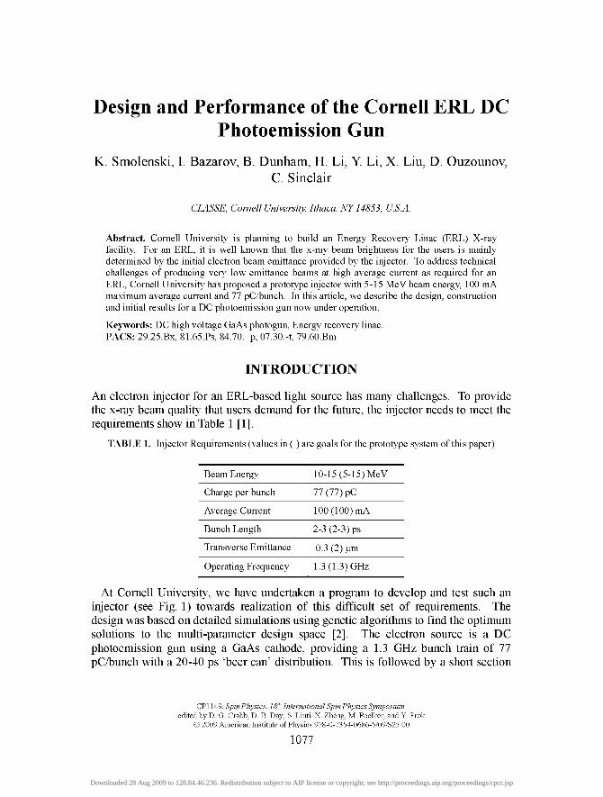
At Cornell University, we have undertaken a program to develop and test such an injector (see Fig. 1) towards realization of this difficult set of requirements. The design was based on detailed simulations using genetic algorithms to find the optimum solutions to the multi-parameter design space [2]. The electron source is a DC photoemission gun using a GaAs cathode, providing a 1.3 GHz bunch train of 77 pC^unch with a 20-40 ps 'beer can' distribution. This is followed by a short section
CY\\A9, SpinPhysics, If? International Spin Physics Symposium edited by D. G. Crabb, D. B. Day, S. Liuti, X. Zheng, M. Poelker, and Y. Prok
© 2009 American Institute of Physics 978-0-7354-0686-5/09/$25.00
1077
Downloaded 28 Aug 2009 to 128.84.46.236. Redistribution subject to AIP license or copyright; see http://proceedings.aip.org/proceedings/cpcr.jsp
for emittance compensation solenoids and a normal conducting buncher cavity [3]. The beam is then accelerated through a cryomodule containing five 2-cell niobium superconducting RF (SRF) cavities, each with individual control of phase and gradient. The cavities have two opposing 50 kW input couplers to feed in 100 kW per cavity. The available RF power allows for either 100 mA at 5 MeV or 33 mA at 15 MeV. After the SRF cavities, an extensive suite of diagnostics allows for a complete characterization of the transverse and longitudinal phase space of the beam. The beam is terminated in an aluminum dump with a capacity for disposing 600 kW of average power. The current status of the complete injector commissioning and beam performance has been reported elsewhere. [4]
ICM buncher quads ^
FIGURE 1. The layout of the Cornell prototype ERL injector.
DC PHOTOEMISSION GUN
Based on the experience of other labs [5] and of the authors, DC photoemission guns provide the best chance of producing the low emittance, high average power beam to meet the needs of an ERL. The present record for average current belongs to the Boeing normal conducting RF (NCRF) gun [6] at 32 mA (25% duty factor), and while other projects continue to push for higher current with NCRF guns, no improvements have been realized. Work on SRF guns has made excellent progress recently [7], but the prospect of obtaining 100 mA average current is still many years away. The DC gun used for the Jefferson Lab FEL project [5] has reliably provided 135 pC bunches at an average current of ~9 mA, and an extension of that technology is the most likely path to meet the needs of an ERL injector in the near future.
High Voltage Gun
Common sense dictates that high initial beam energy and high electric field at the cathode are necessary to overcome the space charge forces in bunched beams and obtain the best possible emittance. Simulations [2] show that higher gun voltage is important for obtaining low emittance up to a certain point, after which the improvement is relatively small. Thus, a DC gun operating in the range of 500-600 kV should meet the emittance goals with the appropriate cathode. To minimize dark current at the operating voltage, the gun must be processed to roughly 25% above the operating value; consequently the Cornell gun has been designed to withstand a 750 kV maximum voltage.
A schematic cutaway of the Cornell DC photoemission gun is shown in Fig. 2, and was designed to meet the requirements in Table 2. The gun was operated for over a year using a test beamline to measure the performance of the gun and cathode before
1078
Downloaded 28 Aug 2009 to 128.84.46.236. Redistribution subject to AIP license or copyright; see http://proceedings.aip.org/proceedings/cpcr.jsp

mating it to the rest of the injector Details of these measurements have been pubhshed elsewhere [8, 9], with the main result that the emittance measurements at 77 pC^unch and 250 kV beam energy match the simulations very closely, giving confidence that the simulations for the entire system are valid. Two difficulties observed involved the laser profile and laser stability. Tails in the phase space distribution were traced (through simulation) to non-uniformities and laser stability across the 'flat-top' laser distribution and variations in the distribution over time. The pointing stability of the laser at the cathode was also an issue, causing jumps in the phase space measurements. The laser itself is stable to 20-30 |im rms, but this increases upon demagnification to the cathode. We have since purchased an active position stabilization device (MRC Systems GmbH) which will reduce the position jitter at the cathode to < 10 |j,m rms.
TABLE 2. DC Gun and Laser Requirements
Operating voltage
Maximum voltage
Average Current
Vacuum during operation
External SF^ pressure
Laser wavelength
Laser pulse shape
Laser pulse length
Phase jitter
500-600 kV
750 kV
100 mA
<lxlO-"Torr
4atm
520 nm
'beer can'
20-40 ps
< 1 ps
All guns of this type suffer from the problem of controlling field emitted electrons from the high voltage surfaces. These electrons can land on the insulator, and if the charge builds up punch-through can occur, causing a vacuum leak. We purchased an insulator with an internal resistive coating (CPI, Inc.) to bleed off these electrons, but it has only been successful up to 450 kV during processing, above which punch-through occurs. In addition, the coating has not adhered well, leaving a layer of dust on the electrodes, certain demise for reaching 750 kV. Two such insulators have been built and tested with similar damage occurring to both. Correlation between the location of edges of the segmented electrode support stalk and the vacuum breaches caused by punch-through have led to the adoption of a single piece stalk to replace the one shown in fig. 2.
Colleagues at Daresbury Lab [10] have built an insulator using a new material from Morgan Advanced Ceramics (AL-970CD) which is more resistant to field emitted electrons, at least up to 500 kV. We are in the process of obtaining a new insulator using this material, and are also investigating the use of segmented insulators [II] which completely block the line of sight between the electrodes and the insulator, but have a much more complicated mechanical structure. For now, we are hmiting the gun voltage to 300 kV to reduce the chance of damage, until a spare is obtained.
1079
Downloaded 28 Aug 2009 to 128.84.46.236. Redistribution subject to AIP license or copyright; see http://proceedings.aip.org/proceedings/cpcr.jsp
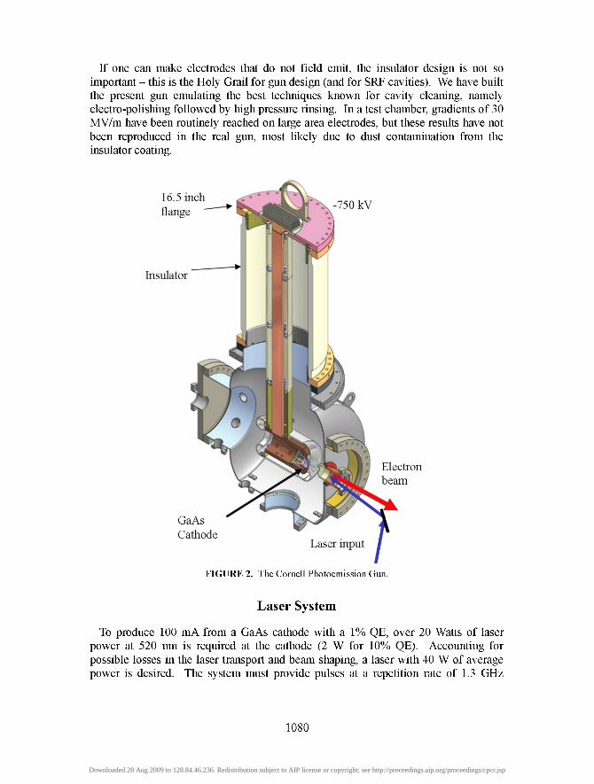
If one can make electrodes that do not field emit, the insulator design is not so important - this is the Holy Grail for gun design (and for SRF cavities). We have built the present gun emulating the best techniques known for cavity cleaning, namely electro-polishing followed by high pressure rinsing. In a test chamber, gradients of 30 MV/m have been routinely reached on large area electrodes, but these results have not been reproduced in the real gun, most likely due to dust contamination from the insulator coating.
16.5 inch flange V -750 kV
Insulator
Electron beam
GaAs Cathode
Laser input
FIGURE 2. The Cornell Photoemission Gun.
Laser System
To produce 100 mA from a GaAs cathode with a 1% QE, over 20 Watts of laser power at 520 nm is required at the cathode (2 W for 10% QE). Accounting for possible losses in the laser transport and beam shaping, a laser with 40 W of average power is desired. The system must provide pulses at a repetition rate of 1.3 GHz
1080
Downloaded 28 Aug 2009 to 128.84.46.236. Redistribution subject to AIP license or copyright; see http://proceedings.aip.org/proceedings/cpcr.jsp

synchronized to the RF master clock (with a timing jitter < 1 ps), and a configurable pulse shape in time and space for minimizing the electron beam emittance.
We have chosen to use a Yb-doped fiber laser system to meet these requirements [12]. Initially, the oscillator was made in-house, but difficulties were encountered in accurately synchronizing it to the RF system. Subsequently, a commercial fiber laser 'clock' was purchased from PriTel Inc. They modified a standard product to work at our pulse repetition rate. The laser is triggered by the RF master clock signal, and the jitter between the output pulse the clock signal is less than 500 fs. The pulses are fed to a single mode fiber amplifier where the pulse energy is boosted to 150 nJ, low enough to prevent any nonlinear distortion. The pulse energy is further increased through amplification in a double clad large mode area fiber amplifier built to work in nearly single mode regime. Currently we have implemented only one such stage and achieved average power of 35 watts at 1040 nm (27 nJ pulse energy). The IR pulses are frequency doubled in a LBO crystal to produce pulses centered at 520 nm and energy of 9 nJ (12 W average power). Additional thermal management is needed to reach higher powers. Laser shaping of the pulses has been described in detail elsewhere in these proceedings [13].
Photocathode Materials
A perfect photocathode for an accelerator electron source would have high efficiency at a convenient laser wavelength, fast response time, long lifetime and a low thermal emittance. Unfortunately, no such cathode exists today, although the search continues. A number of different photocathodes meet some of these criteria, so tradeoffs have to be made depending on the requirements of the particular system. For an ERL, obtaining 100 mA average current means high quantum efficiency (QE) photocathodes are a necessity.
Semiconductor photocathodes are currently the best choice for high QE and low emittance. Examples are GaAs, Cs2Te, GaN, and K2CsSb. Both Cs2Te and GaN show promise but require UV hght but there are no laser systems available to produce enough average power in the UV Both GaAs and K2CsSb have 5-10% QE for -520 nm light, where high average power lasers are readily available. At Cornell, we have chosen to use GaAs, but are still considering other cathodes depending on the application.
As mentioned earlier, it is possible to recover the intrinsic thermal emittance from the cathode using a carefully designed emittance compensation scheme for the bunch charges of interest to an ERL [2]. Of all the cathodes available, GaAs has the lowest thermal emittance [7], so is the cathode of choice for an ERL. Unfortunately, the QE is near a minimum when the thermal emittance is smallest (close to the band gap), thus unsuitable for high average current. In addition, it is well known that at -780 nm a fast laser pulse will generate an electron beam with a 20-40 ps tail, which is not acceptable for low emittance operation. For shorter wavelengths (-520nm) recent measurements [10] show that the response time is quite fast (-1 ps) as long as the QE is not too high (< 10%). This points out some of the tradeoffs one has to make even when using GaAs, and we have chosen an operating wavelength of 520 nm as the best compromise between QE, thermal emittance and response time.
1081
Downloaded 28 Aug 2009 to 128.84.46.236. Redistribution subject to AIP license or copyright; see http://proceedings.aip.org/proceedings/cpcr.jsp

The last important parameter is cathode lifetime. The cathodes described above are all sensitive to chemical poisoning to some extent, and require ultra-high vacuum. GaAs is the most sensitive, unfortunately, requiring vacuum levels < 10"" Torr for successful operation. An additional lifetime limiter is ion back-bombardment which further reduces QE. The electron beam can ionize residual gas molecules anywhere along their path, which can then be accelerated back towards the cathode surface. Jefferson Lab [14] has carried out extensive measurements at 10 mA average current, and has measured cathode lifetimes as high as 10^ C/cm^ (the amount of charge extracted per cm^ when the QE has fallen by 1/e). One can use this data to estimate that a 10 W maximum power laser system should be able to provide 100 mA over 100 hours with a 1.8 mm diameter laser spot [15]. Such performance has not been demonstrated yet, and it is certainly an optimistic estimate.
Vacuum System
In order to meet the extreme vacuum levels required for sufficient cathode lifetime both reductions in outgassing and massive pumping have been implemented. The stainless steel vacuum vessel and all stainless internal components including the electrodes have been air-fired for 100 hours at 400°C to reduce their hydrogen outgassing rate, the primary residual gas constituent [16]. A typical 160°C vacuum bake follows assembly of the gun. The pumping scheme consists of a 400 1/sec Perkin-Elmer ion pump and 20 NEG modules lining the walls of the gun vessel. The NEG modules are of the WP1650-ST 707 type supplied by SAES Getters and provide approximately 15,000 1/sec of pumping for hydrogen. Typical static pressure in the gun is below 6x10"'^ mbar.
Small vacuum leaks have opened at the Conflat flange joints between the insulator and the gun vessel during processing, perhaps caused by heating of the gasket by field emission. New triple point protection rings that cover the vacuum joint were installed and no further leaks have occurred.
Cathode Preparation System
A modular cathode preparation system is attached to rear of the gun vessel to load, clean, prepare, and store the semiconductor cathodes. Vacuum isolation between each chamber (load lock, hydrogen cleaning and heating, cathode surface preparation) allows for multiple cathodes to be accommodated at once. For example a backup cathode could be heat cleaned at the same time the primary cathode is being cesiated. Its design allows for flexibility in the cathode material and is extensible for future cathode material development. Im long orthogonal manipulator arms transfer the cathode pucks between processing chambers and also move the prepared cathode into the electrode structure.
COMMISSIONING RESULTS AND PLANS
Processing of the electrode structure at a rate of IkV/Hr. has been successful only to 450KV where punch through occurred (as described earher). The gun typically
1082
Downloaded 28 Aug 2009 to 128.84.46.236. Redistribution subject to AIP license or copyright; see http://proceedings.aip.org/proceedings/cpcr.jsp

operates at 250 kV and we are not pushing the voltage higher until a backup insulator is acquired. Now in operation for two years, the gun routinely provides pulsed beams of varying bunch charge for diagnostic measurements. Average current as high as 20mA at 250kV has been achieved for short periods. The near term plans include extensive sets of phase space measurements along with the push for higher currents.
ACKNOWLEDGEMENTS
This work was supported by NSF grant PHY 0131508.
REFERENCES
1. S. M. Gruner and M. Tigner, Eds., "Study for a proposed Phase I Energy Recovery Linac (ERL) synchrotron light source at Cornell University", CHESS Technical Memo 02-003, Jefferson Laboratory Report No. JLAB ACT-01-04 (2001).
2. I.V. Bazarov, et al, "Multivariate optimization of a High Brightness DC Gun Photoinjector", PRST AB, 8, 034202 (2005).
3. S. Belomestnykh, et al., "Commissioning of the Cornell ERL Injector RE Systems", 2008 European Particle Ace. Conf, Genoa, Italy 832-834 (2008).
4. B. Dunham, et al., "Eirst Tests of the Cornell University ERL Injector", Linac 08 Proceedings, In Press (2008).
5. C. Hernandez-Garcia, et al, "A High Average Current DC GaAs Photocathode Gun for ERLs and EELs", 2005 Particle Ace. Conf, Knoxville, TN, 3117-3119 (2005).
6. D. Dowell, etal, Nucl. Instr Meth. A356, 167 (1995). 7. A. Arnold, et al, "Development of a Superconducting RE Photoinjector", Nucl. Instr Meth., A 577,
440 (2007). 8. I. Bazarov et al., "Thermal emittance and response time measurements of negative electron affinity
photocathodes", J. Appl. Phys., 103 (2008) 054901. 9. I. Bazarov et al, "Efficient temporal shaping of electron distributions for high brightness
photoemission guns", PRST AB 11 (2008) 040702. 10.R.J. Smith, Daresbury Lab, personal communication. 11. J. Haimson, IEEE Trans. Nucl. Sci. NS 22, 1354 (1975. 12.D. Ouzounov, et al, "The Laser System for the ERL Electron Source at Cornell", 2007 Particle Ace.
Conf, Albuquerque, NM, 530-532 (2007). 13.D. Ouzounov, et al. These Proceedings.
1083
Downloaded 28 Aug 2009 to 128.84.46.236. Redistribution subject to AIP license or copyright; see http://proceedings.aip.org/proceedings/cpcr.jsp