design considerations for a storage ring resonant cavity ... · design considerations for a storage...
TRANSCRIPT
Design considerations for astorage ring resonant cavity
beam position monitor /tilt monitor for SPX
Glenn DeckerOctober 1, 2010
ASD Seminar
The Monolith
Dave Bowman: Open the pod bay doors, HAL.
HAL: I’m sorry, Dave. I’m afraid I can’t do that.
Dave Bowman: What’s the problem?
HAL: I think you know what the problem is just as
well as I do.
Dave Bowman: What are you talking about, HAL?
HAL: This mission is too important for me to
allow you to jeopardize it.

h
w
d
x
y
z
(0,0,0)
fmnp =c
2 [ mw( )
2+ n
h( )2 p
d( )2
+ ]
fmn0 =c
2 [ mw( )
2 nh( )
2+ ]
1/2
1/2
Ez = Ez0 sin(mπx/w) sin(nπy/h)
Bx = Bx0 sin(mπx/w) cos(nπy/h)
By = By0 cos(mπx/w) sin(nπy/h)
Pillbox TM modes p = 0;independent of z:
Rectangular Cavity Modes
E
B
h
w
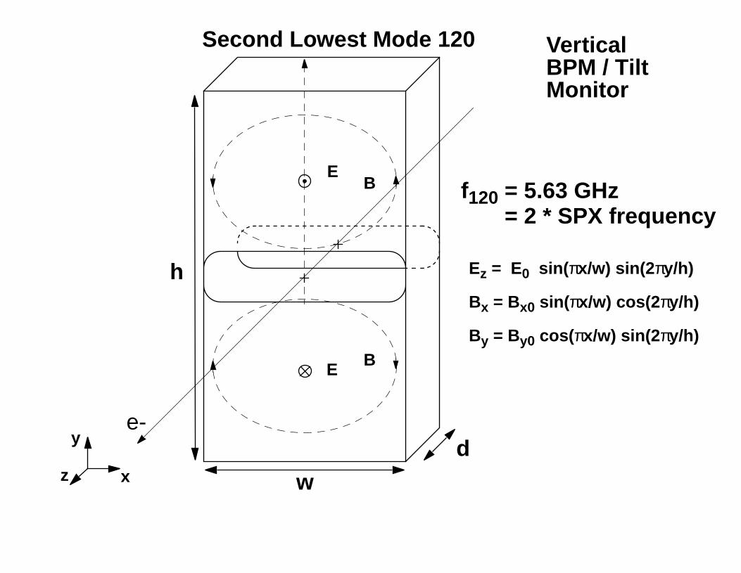
Second Lowest Mode 120
dx
y
z
Ez = E0 sin(πx/w) sin(2πy/h)
Bx = Bx0 sin(πx/w) cos(2πy/h)
By = By0 cos(πx/w) sin(2πy/h)
f120 = 5.63 GHz
E
B
e-
VerticalBPM / TiltMonitor
= 2 * SPX frequency
h=w
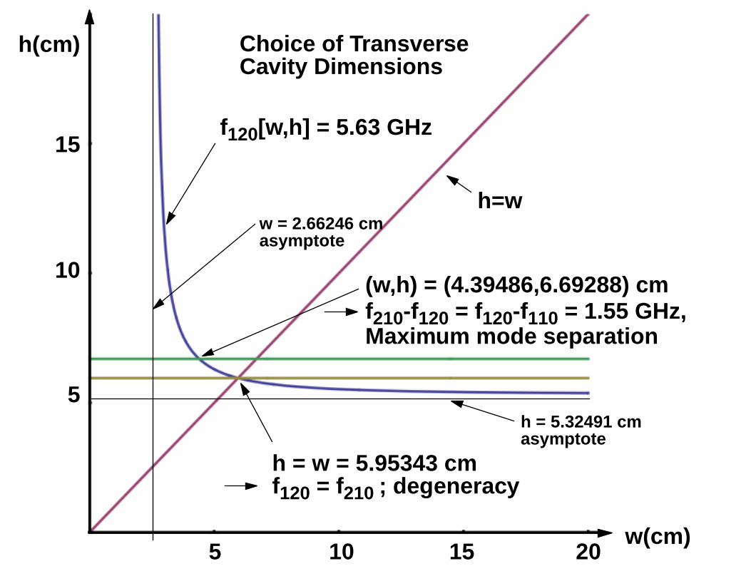
h = w = 5.95343 cm
(w,h) = (4.39486,6.69288) cmf210-f120 = f120-f110 = 1.55 GHz,Maximum mode separation
5 10 15 20
h(cm)
10
15
5
Choice of Transverse
f120 = f210 ; degeneracy
h = 5.32491 cmasymptote
w = 2.66246 cmasymptote
Cavity Dimensions
f120[w,h] = 5.63 GHz
w(cm)
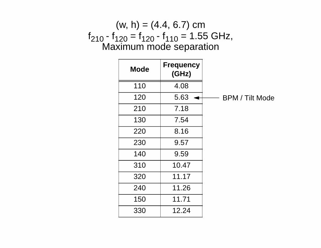
ModeFrequency
(GHz)
110 4.08
120 5.63
210 7.18
130 7.54
220 8.16
230 9.57
140 9.59
310 10.47
320 11.17
240 11.26
150 11.71
330 12.24
(w, h) = (4.4, 6.7) cmf210 - f120 = f120 - f110 = 1.55 GHz,
Maximum mode separation
BPM / Tilt Mode
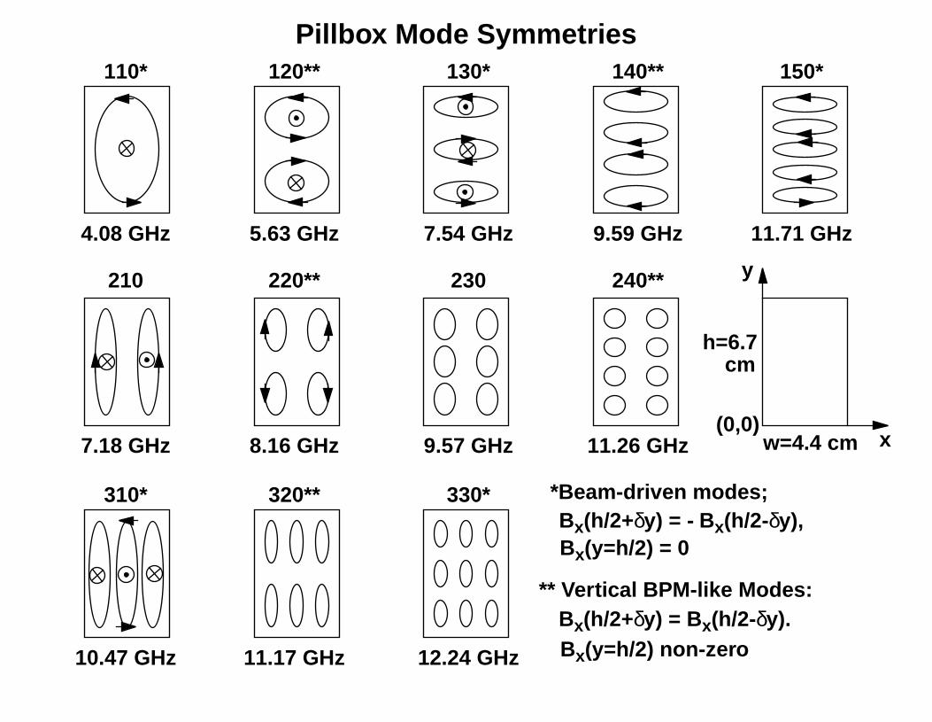
110*
210
4.08 GHz 5.63 GHz
120**
7.18 GHz
220**
8.16 GHz
310*
130* 140**
7.54 GHz 9.59 GHz
10.47 GHz
320**
11.17 GHz
230
9.57 GHz
150*
11.71 GHz
240**
11.26 GHz
330*
12.24 GHz
Pillbox Mode Symmetries
*Beam-driven modes;
w=4.4 cm
h=6.7cm
x
y
** Vertical BPM-like Modes:
Bx(h/2+δy) = - Bx(h/2-δy),
Bx(h/2+δy) = Bx(h/2-δy).
(0,0)
Bx(y=h/2) = 0
Bx(y=h/2) non-zero
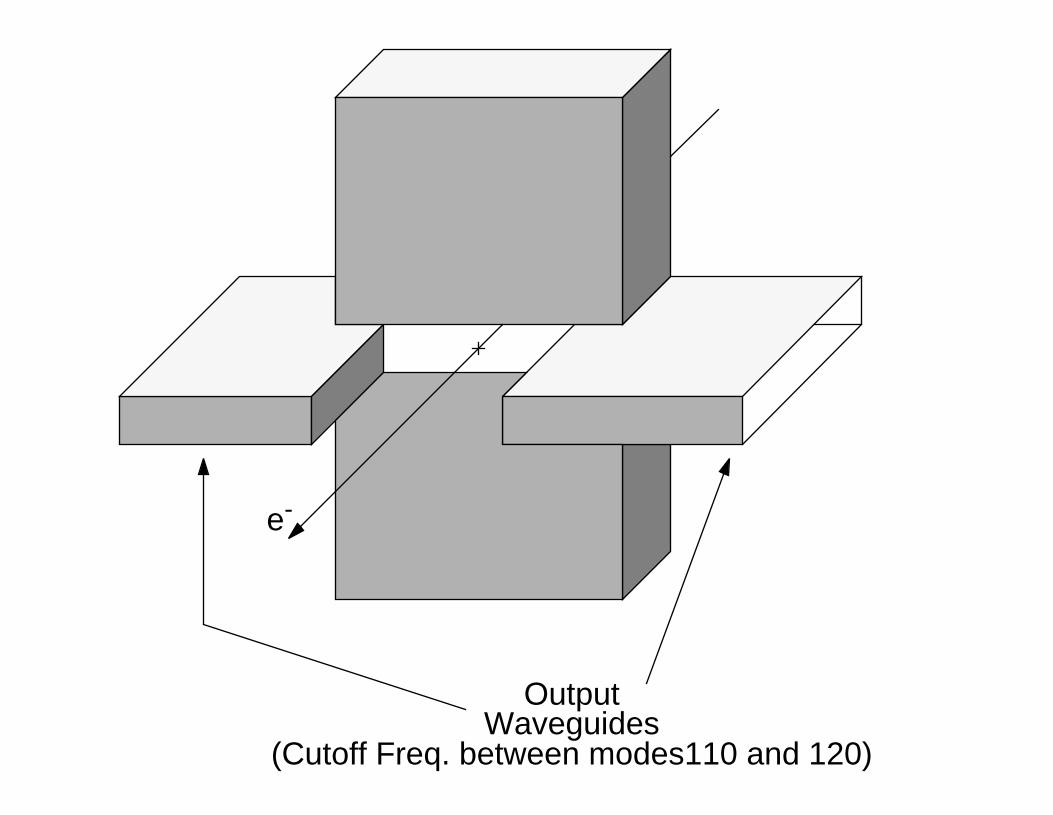
Output
e-
Waveguides(Cutoff Freq. between modes110 and 120)
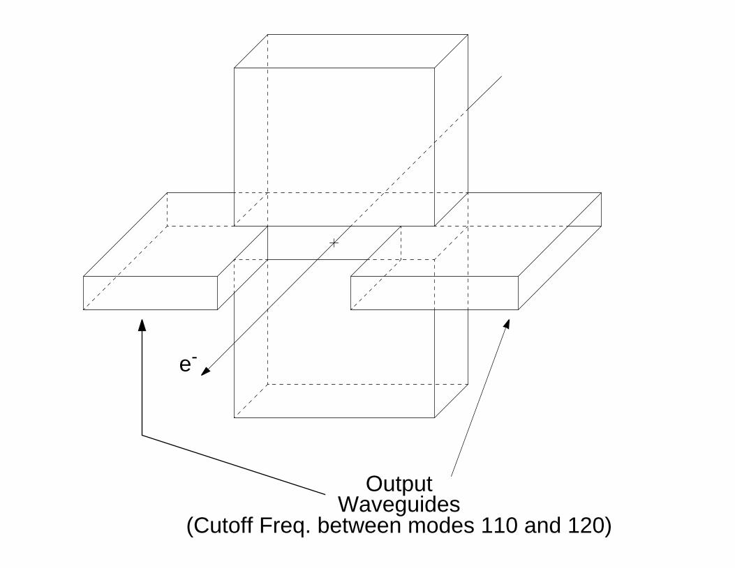
e-
OutputWaveguides
(Cutoff Freq. between modes 110 and 120)

e-
e-
E
BE
B
EB
Top View
Front ViewSide
EB
RFRF
Two-sided Waveguide Couplers
View
TE10
x
y
Orthographic Projection
E
B
B
E
B
B
E
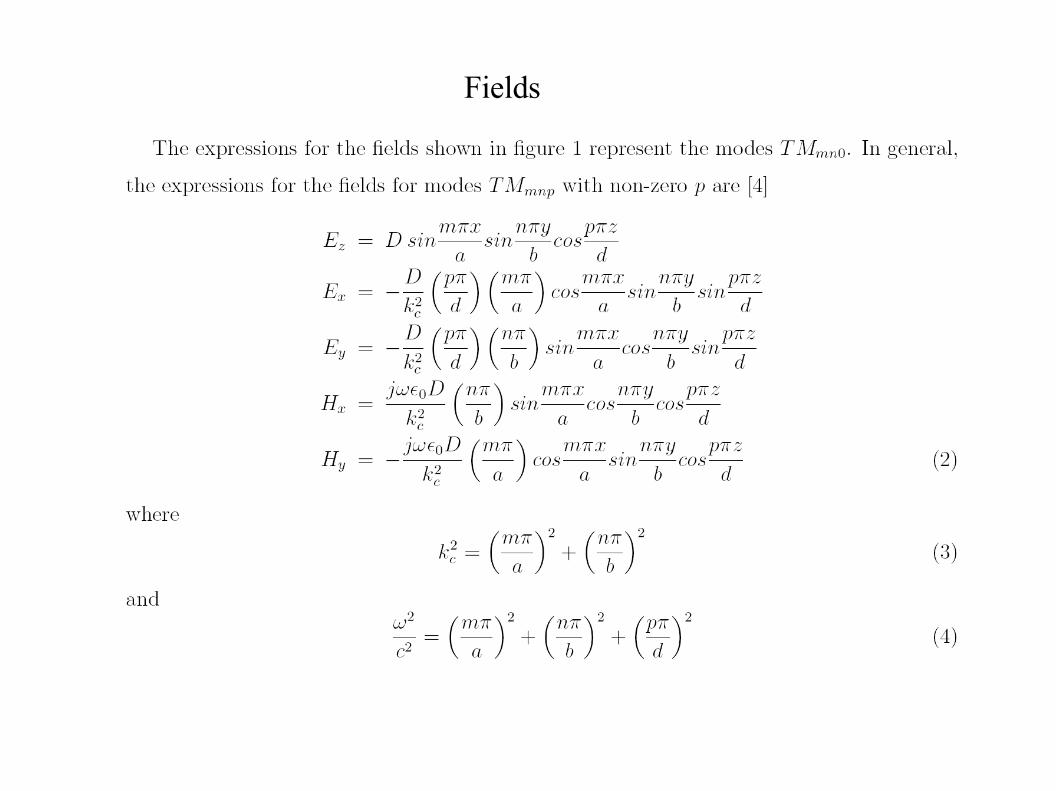
Fields
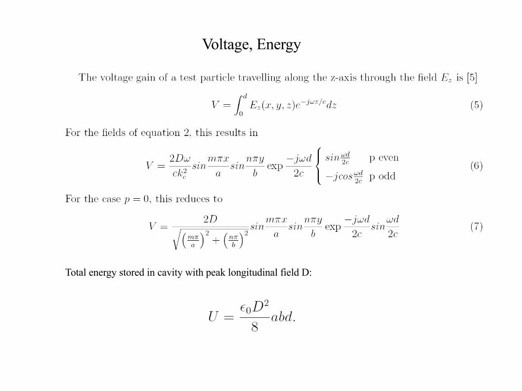
Total energy stored in cavity with peak longitudinal field D:
Voltage, Energy

Bunching Factor Untilted Beam
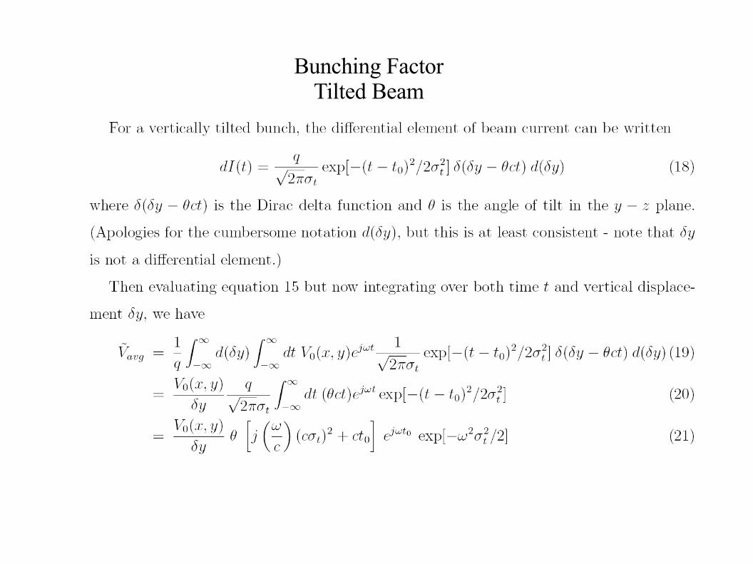
Bunching Factor Tilted Beam

The energy deposited into mode TMmn0 by a point charge q is q2
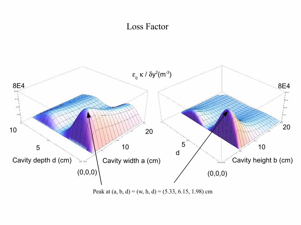
Loss Factor
(0,0,0)
Cavity width a (cm)Cavity depth d (cm)
10
20
5
10
d
(0,0,0)
Cavity height b (cm)
5 10
20
0 / y2(m-3)
8E48E4
Loss Factor
Peak at (a, b, d) = (w, h, d) = (5.33, 6.15, 1.98) cm
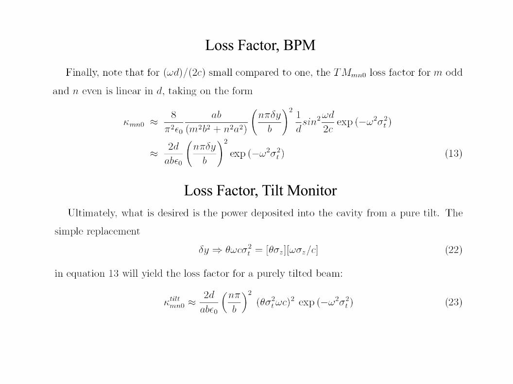
Loss Factor, BPM
Loss Factor, Tilt Monitor
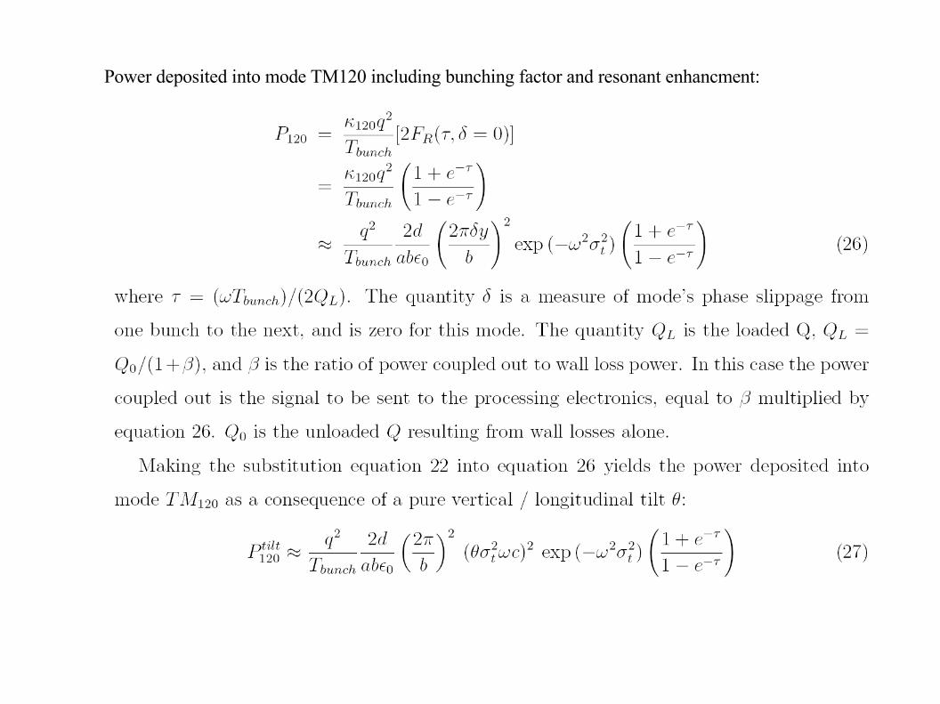
Power deposited into mode TM120 including bunching factor and resonant enhancment:
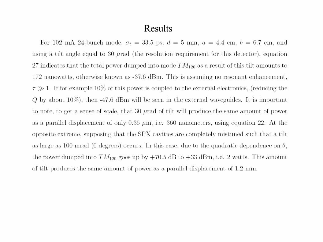
Results
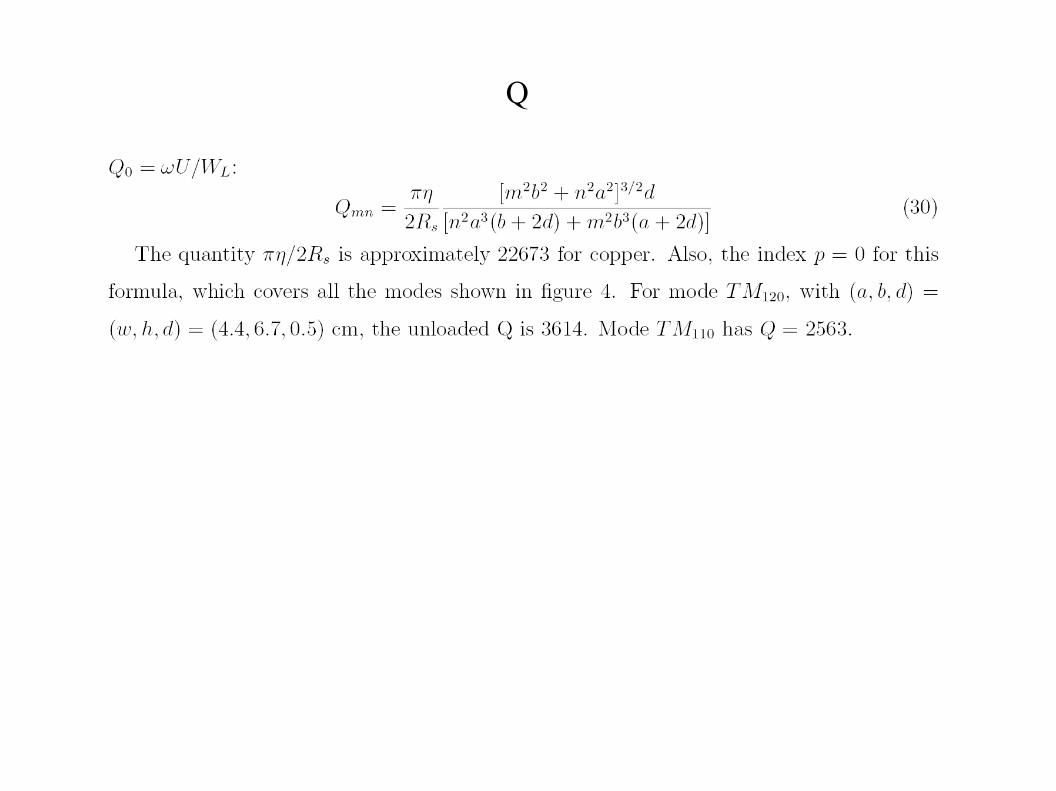
Q
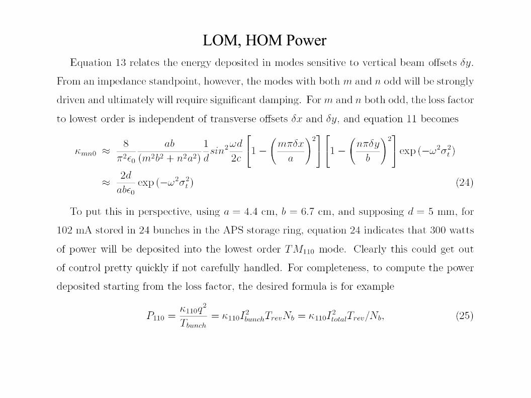
LOM, HOM Power
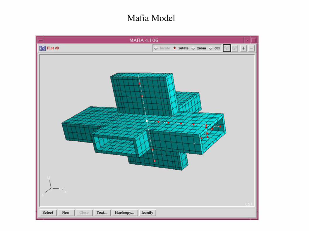
Mafia Model
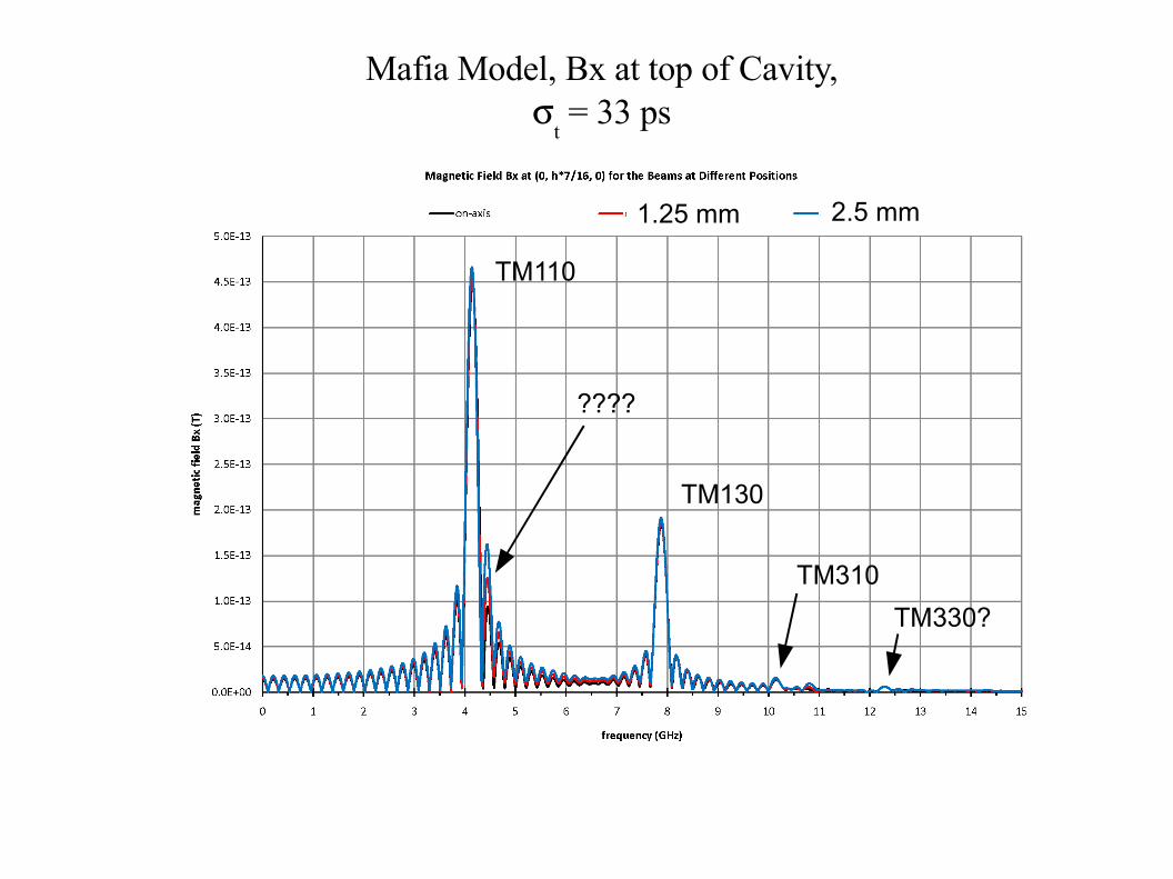
Mafia Model, Bx at top of Cavity,
t = 33 ps
TM110
TM130
TM310
TM330?
????
1.25 mm 2.5 mm
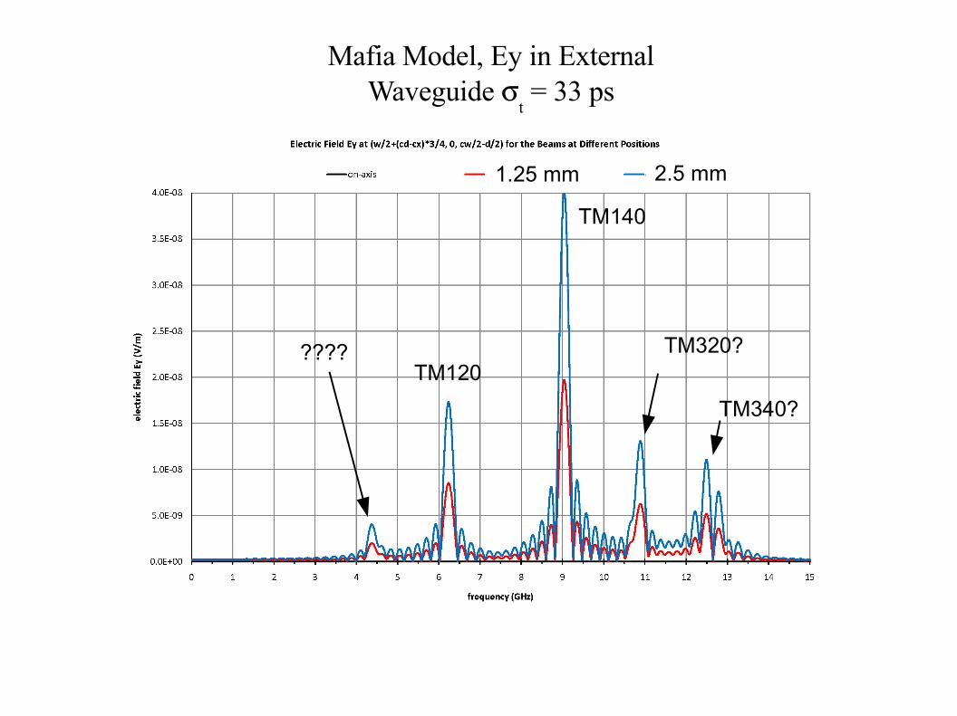
Mafia Model, Ey in External Waveguide
t = 33 ps
TM120
TM140
TM320?
TM340?
????
1.25 mm 2.5 mm

e-
e-
E
BE
B
EB
Top View
Front View Side
EB
View
TE10
LOMH-Loops,
To ProcessingElectronics
Top TopLoop Loop
BottomLoop
BottomLoop
E-probe
HeavyCoupling E
B
B
E
B
B
E
LOM Loop Couplers
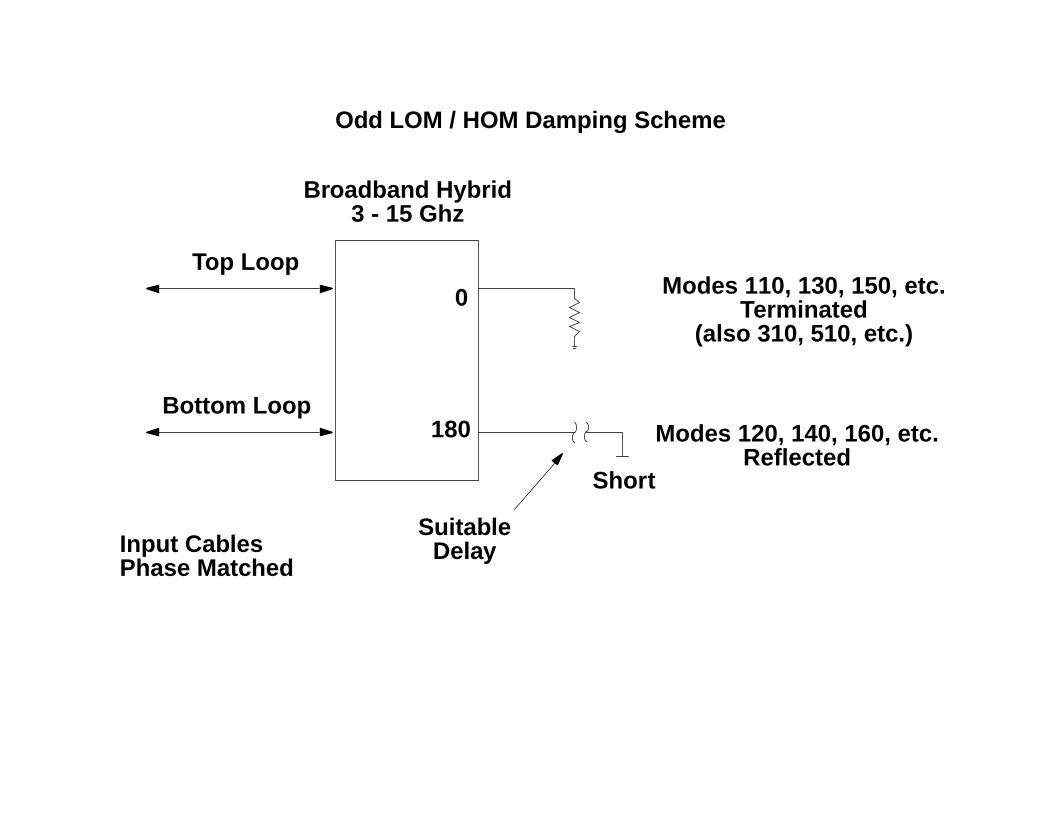
Top Loop
Bottom Loop
0
180
Modes 110, 130, 150, etc.
Short
Modes 120, 140, 160, etc.
Terminated
Reflected
SuitableDelay
Broadband Hybrid
Odd LOM / HOM Damping Scheme
3 - 15 Ghz
(also 310, 510, etc.)
Input CablesPhase Matched
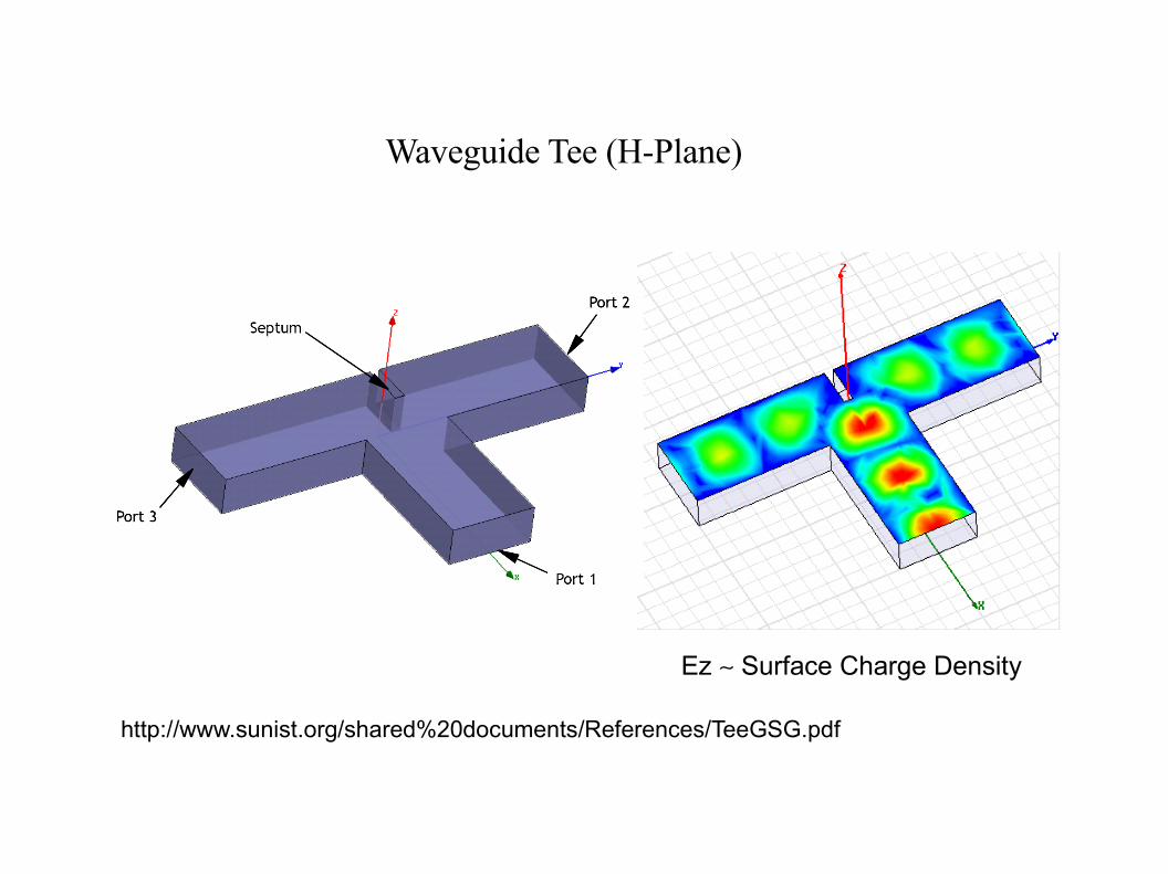
Waveguide Tee (H-Plane)
http://www.sunist.org/shared%20documents/References/TeeGSG.pdf
Ez Surface Charge Density
E
BE
B
EB
BE
EB
BE
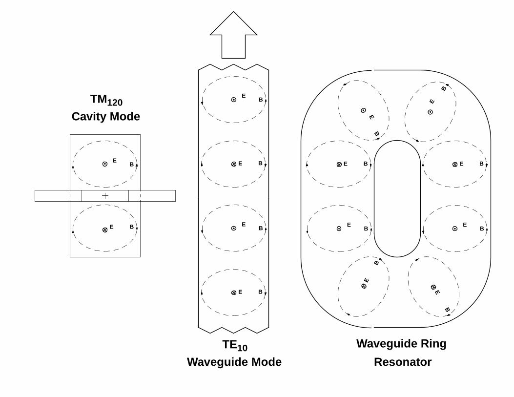
TM120
Cavity Mode
TE10
Waveguide Mode
EB
BE
EB
B
E
E
B
BE
EB
B
E
Waveguide Ring
Resonator
E
B
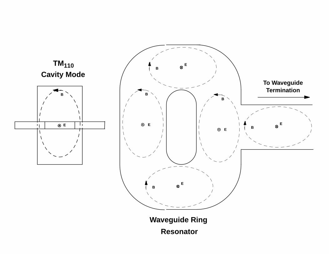
TM110
Cavity Mode
Waveguide Ring
Resonator
E
B
B
E
B
E
BE
BE
To WaveguideTermination
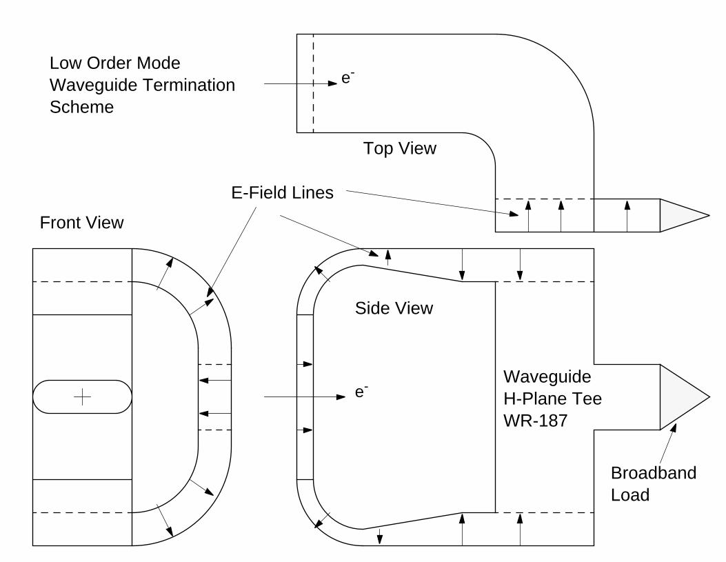
e-
e-
Front View
Side View
Top View
WaveguideH-Plane TeeWR-187
Low Order ModeWaveguide TerminationScheme
BroadbandLoad
E-Field Lines
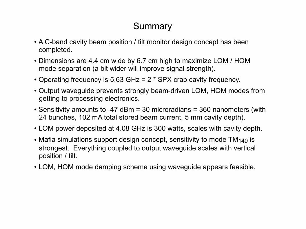
Summary
● A C-band cavity beam position / tilt monitor design concept has been completed.
● Dimensions are 4.4 cm wide by 6.7 cm high to maximize LOM / HOM mode separation (a bit wider will improve signal strength).
● Operating frequency is 5.63 GHz = 2 * SPX crab cavity frequency.● Output waveguide prevents strongly beam-driven LOM, HOM modes from
getting to processing electronics.● Sensitivity amounts to -47 dBm = 30 microradians = 360 nanometers (with
24 bunches, 102 mA total stored beam current, 5 mm cavity depth).● LOM power deposited at 4.08 GHz is 300 watts, scales with cavity depth.
● Mafia simulations support design concept, sensitivity to mode TM140 is strongest. Everything coupled to output waveguide scales with vertical position / tilt.
● LOM, HOM mode damping scheme using waveguide appears feasible.