design, construction and commissioning of …umpir.ump.edu.my/id/eprint/5360/1/cd5881.pdf ·...
TRANSCRIPT

DESIGN, CONSTRUCTION AND COMMISSIONING OF MICROALGAE
PHOTOBIOREACTOR
AHMAD SHAFIQ BIN MOHAMAD
A project report submitted in partial fulfillment of the requirements for the award o f the
bachelor degree of Chemical Engineering (Biotechnology)
Faculty of Chemical and Natural Resources Engineering
Universiti Malaysia Pahang
APRIL 2010

viii
TABLE OF CONTENTS
CHAPTER
1
2
SUBJECT
TITLE
DECLARATION OF ORIGINALITY AND
EXCLUSIVENESS
DEDICATION
ACKNOWLEDGEMENT
ABSTRACT
ABSTRAK
TABLE OF CONTENTS
LIST OF TABLES
LIST OF FIGURES
LIST OF NOMENCLATURES
INTRODUCTION
1.1 Background of study
1.2 Problem statement
1.3 Objectives
1.4 Scopes of the study
1.5 Rationale and significant
LITERATURE REVIEW
2.1 Photobioreactor (PBR) design
2.2 Microalgae and its potential
PAGE
i
ii
iii
iv
v
vi
viii
x
xi
xii
1
2
2
3
3
4
8

ix
3
4
5
2.3 Comparison of raceways and tubular PBR
2.4 Acceptability of microalgal biodiesel
METHODOLOGY
3.1 Introduction
3.2 Design of airlift photobioreactor
3.3 Construction of airlift photobioreactor
3.3.1 Support structure construction
3.3.2 PBR structure construction
3.4 Commissioning process of PBR
RESULTS AND DISCUSSION
4.1 Introduction
4.2 Results
4.2.1 Final PBR design
4.2.2 Construction of PBR
4.2.3 Commissioning of PBR
4.3 Discussion
CONCLUSIONS AND RECOMMENDATIONS
5.1 Conclusion
5.2 Recommendation
REFERENCES
APPENDIX A
10
12
13
13
14
14
14
16
17
17
17
18
19
21
22
22
24
26

xii
LIST OF NOMENCLATURES
PBR - Photobioreactor
p - Biomass productivity
Cb - Cell concentration
D - Dilution rate
µ - Specific growth rate
µmax - Maximum growth rate

x
LIST OF TABLES
TABLE
2.1
2.2
3.1
4.1
TITLE
Comparison of some sources of bioethanol
Comparison of raceway and photobioreactor
methods
Type and quantity of fitting used
Results for commissioning process of airlift PBR
PAGE
9
10
16
21

1
CHAPTER 1
INTRODUCTION
1.1 Background Of Study
Culture of microalgae in open ponds and raceway is well developed but only a few
species can be maintained in traditional open systems that control contamination by using
highly alkaline or saline selective environments. Although the term ‘photobioreactor’ has
been applied to open algal ponds and channels, it is best reserved for devices that allow
monoseptic culture which is fully isolated from a potentially contaminating environment.
Fully closed photobioreactors provide opportunities for monoseptic culture of a greater
variety of algae than is possible in open systems (E. Molina et al , 2001) .
Photobioreactors has been used widely in culturing microalgae. Although it has
large potential, the design nowadays is taking too much space in open ponds and raceways.
By this research, we will study the effect of column depth and mixing towards sunlight and
photosynthesis of microalgae in the design model photobioreactor. This photobioreactor
will simulate the concept of mixing in the open ponds as in upscale design. Previous
research shows that the design of photobioreactors needs large space and area, for example
open ponds and raceways.

2
In an optimal system where no other factors limit, the light availability determines
the rate of photosynthesis and productivity. However, excessive light can be harmful and is
known to produce a photoinhibitory response (Bannister, 1979;Aiba, 1982).We will also
need to design an effective CO2 sparger so that we can monitor and study the optimum
carbon dioxide supply for microalgae’s growth. The effect of this study will help to make
an upscale design of photobioreactors that will save amount of space of lands or ponds.
1.2 Problem Statement
Designing a photobioreactor for microalgae needs many considerations to be put in
to produce the optimum growth of the microalgae itself. In the previous research, large
area needed to locate the photobioreactor. For the optimum growth of the microalgae
several parameter has to be manipulated, that is:
a) Pressure of air sparged from the air compressor
b) Mixing in the airlift photobioreactor
1.3 Objectives
The objective of this research is to:
i. Design and construct microalgae photobioreactor.
ii. Test the airlift photobioreactor for flowrate and mixing by manipulating the
pressure of air sparged through the airlift by using water.

3
1.4 Scopes
Scopes of the study were identified in order to achieve the research objectives. The
construction and commissioning process have been done in Engineering Workshop
FKKSA UMP. About 2 and a half month is taken to construct the photobioreactor. For this
research, the scopes of study are:
i. Photobioreactor design
ii. Manipulated variable:
Mixing
Flowrate of air sparged.
iii.Relationship between the PBR design and manipulated variable.
1.5 Rationale and Significance
Microalgae photobioreactor has been used widely in advanced country to grow
microalgae for their oils. This study will contribute and enhance the research on
microalgae photobioreactor and thus the production of biodiesel from microalgae.
Optimum pressure for air sparging into the PBR to make the liquid flow and to create
turbulence for effective mixing will be determine.

xi
LIST OF FIGURES
FIGURE
2.1
2.2
2.3
4.1
4.2
TITLE
Example of microalgae photobioreactor design
The gas- liquid separator
Microalgae recovered from broth by filtration
Schematic diagram of the airlift PBR
Pressure of air sparged versus time graph
PAGE
5
6
11
18
20

v
ABSTRACT
Oil can potentially be produced by microalgae which then can be converted into
biodiesel. Although it has large potential, the design of reactor to grow microalgae
nowadays is taking too much space in open ponds and raceways. The objective of this
research is to design, construct and commission an airlift photobioreactor which will
enable the operator to monitor and control mixing and the level of dissolved CO2 in the
medium and as well exposed it to sunlight for the microalgae to undergo photosynthesis.
The construction comprises of two stages namely the first stage on the construction of the
vertical airlift photobioreactor which will provide the flow, and the second stage on the
construction of the horizontal solar receiver photobioreactor which will enable the
microalgae to tap on the sunlight for photosynthesis. The work represented in this thesis
concern only on the first stage. For this first stage, the most important factor is the mixing.
We can manipulate it by varying the flowrate of air sparged through the airlift bioreactor.
There were three series of methods that has been done to complete this research that is
design, construct and commissioning process. The design photobioreactor has been used to
construct the airlift bioreactor and the support structure. For the commissioning process,
blue dye has been used to determine the dispersion pattern in the airlift photobioreactor. It
was found that the blue dye was dispersed primarily because of the sparging of the air,
even before the flowrate reaches turbulence which would have cause the mixing. After air
has been sparged for first try at 2 psi, it takes 2 and a half minute for the dye to complete
the cycle in the PBR. For 4 psi, 68 seconds, at 6 psi it takes 50 seconds and for the last at 8
psi, it takes 44 seconds for a complete cycle. Even though at 8 psi it takes shorter time to
complete a cycle, overflow has been observed at the liquid-gas disengagement chamber.
The optimum pressure of air sparged has been determined to be at 6 psi. The research has
completely achieved all its objectives.

vi
ABSTRAK
Minyak yang berpotensi dapat dihasilkan oleh mikroalga yang kemudiannya dapat
ditukar menjadi biodiesel. Walaupun mempunyai potensi yang besar, desain reaktor untuk
pertumbuhan mikroalga pada masa ini mengambil ruang yang terlalu besar di kolam
terbuka. Tujuan dari penelitian ini adalah untuk mereka, membangun dan mengoperasi
fotobioreaktor penaik udara yang akan membolehkan operator untuk memantau dan
mengawal pencampuran dan kadar CO2 terlarut dalam media dan juga terdedah kepada
sinar matahari untuk membolehkan mikroalga menjalani fotosintesis. Pembinaan terdiri
daripada dua tahap iaitu pada tahap pertama pembangunan fotobioreaktor penaik udara
menegak yang akan memberikan aliran, dan tahap kedua pada pembangunan
fotobioreaktor penerima suria mendatar yang akan membolehkan mikroalga untuk
terdedah pada cahaya matahari untuk proses fotosintesis. Tesis ini hanya merangkumi
tahap yang pertama. Untuk tahap pertama ini, faktor yang paling penting adalah
pengadukan. Kita dapat memanipulasi parameter ini dengan memvariasikan laju aliran
udara yang disembur melalui bioreaktor penaik udara. Ada tiga rangkaian kaedah yang
telah dilakukan untuk menyelesaikan kajian ini iaitu rekabentuk, proses pembinaan dan
pengoperasian. Rekaan fotobioreaktor telah digunakan untuk membina bioreaktor penaik
udara dan struktur penyokong. Untuk proses pengoperasian, pewarna biru telah digunakan
untuk menentukan pola penyebaran di fotobioreaktor penaik udara. Didapati bahawa
pewarna biru itu tersebar terutamanya kerana semburan udara, bahkan sebelum mencapai
laju aliran yang akan menyebabkan pengadukan. Setelah udara disembur, untuk percubaan
pertama pada 2 psi, diperlukan dua minit dan tiga puluh saat untuk pewarna biru
melengkapkan kitaran di dalam fotobioreaktor tersebut. Untuk 4 psi, 68 saat diperlukan,
manakala pada 6 psi, 50 saat diperlukan. Untuk yang terakhir pada 8 psi, 44 saat
diperlukan untuk kitaran yang lengkap. Meskipun pada 8 psi waktu yang lebih singkat

vii
diperlukan untuk sebuah kitaran, limpahan pada bahagian pengasing gas dan cecair telah
diamati. Tekanan udara optimum semburan telah ditetapkan sebanyak 6 psi. Kajian telah
sepenuhnya mencapai semua tujuannya.
4
CHAPTER 2
LITERATURE REVIEW
2.1 Photobioreactor (PBR) Design
In an airlift driven tubular photobioreactor, the recirculation velocity of the culture
and oxygen removal characteristics are closely linked. The culture performance is critically
dependent on attaining an optimal design that provides the requisite flow and gas
exchange. In addition, the photobioreactor geometry must maximize capture of sunlight
while minimizing the land surface occupied (Molina et al., 2001). Effects of tube length,
flow velocity, the airlift column height, and the geometric configuration of the solar
receiver on various performance parameters are discussed. A photobioreactor designed
using the approach outlined is proved for culture of the microalga Phaeodactylum
tricornutum. Figure 2.1 shows the example of microalgae photobioreactor that consists of
airlift and its solar collector.

5
Fig. 2.1.: Example of Microalgae Photobioreactor Design
The airlift column circulates the culture through the solar collector tubing where
most of the photosynthesis occurs. The oxygen produced by photosynthesis accumulates in
the broth until the fluid returns to the airlift zone where the accumulated oxygen is stripped
by air. A gas–liquid separator in the upper part of the airlift column prevents gas bubbles
from recirculating into the solar collector. The solar loop is designed to efficiently collect
the solar radiation, minimize resistance to flow, and occupy minimal area to reduce the
demand for land. In addition, the diameter of the solar tubing is selected so that the volume
of the dark zone (i.e. one with light intensity below saturation) is kept to a minimum. Also,
the interchange of fluid between the light and the dark zones in the solar loop must be
sufficiently rapid that element of fluid does not reside continuously in the dark zone for
long (J.C Ogbanna., H. Tanaka, ,1997).

6
The airlift device must fulfill two needs: the circulation of fluid through the solar
loop and stripping of oxygen from the broth. The volume of the broth in the airlift device
needs to be small compared to the volume in the solar loops that cells spend as much time
as possible in the relatively better illuminated loop. In this work, the riser and downcomer
tubes of the airlift device were vertical extensions of the ends of the solar loop. The
volume in the gas- liquid separator was minimized by reducing the spacing between the
parallel walls (Figure 2.2) to the width of the riser (or the downcomer) tube.(Figure 2.1).
The bottom of the separator was slanted at 600 relative to horizontal, so that the solid
would not settle permanently.
Figure 2.2: The gas- liquid separator
The head zone of the airlift column (Figure 2.1) was designed for almost complete
separation of the gas from the liquid, before the broth recirculated into the solar collector.
Complete disengagement of gas meant that the driving force for liquid circulation was the
maximum attainable for any aeration rate in the airlift riser. For the disengagement of gas,

7
the distance between the entrance and the exit of the separator zone should be that smallest
bubble can rise out of the fluid by the time it exits the separator and moves into the
downcomer (Chisti and Moo-Young, 1993)
Availability and intensity of light are the major factors controlling productivity of
photosynthetic cultures. In continuous culture as typically practiced for microalgae, the
biomass productivity (p) is a function of the cell concentration (Cb) in the effluent and the
dilution rate (D); thus, p=DCb. (C.G. Lee, B.Ø. Palsson, 1995). At steady state, the
dilution rate equals the specific growth rate (µ) which is governed by the amount of light,
the rate controlling factor. Generally, µ increases with increasing irradiance, reaching a
maximum value, µmax. Further increase in irradiance may actually inhibit growth - a
phenomenon known as photoinhibition (E. Molina et al., 1999).
An efficient large scale PBR has yet to be developed [Ogbanna et al., 1997].This
has left commercial production of algae to open ponds. Open ponds do not provide
conditions necessary for high density algal biomass production because of diurnal and
annual variation in light intensity and temperature. Chen (1996) states that enclosed PBRs
have the following advantages over open pond production.
1. Better control of algal culture
2. Large surface-to-volume ratio
3. Better control of gas transfer
4. Reduction in evaporation of growth medium
5. More uniform temperature
6. Better protection from outside contamination
7. Higher algal cell densities are possible.
Removal of contaminates from air streams requires that the air be brought into
contact with the growth medium (principally water) in the reactor area of the PBR. Air
with contaminates may be moved over the surface of the growth medium, but this will

8
likely yield low gas transfer rates and will not enhance mixing of the algae-growth medium
solution. Without mixing, the algae will tend to settle towards the lower portion of the PBR
(Lee and Palsson, 1995). Mixing also reduces temperature gradients and enhances nutrient
distribution in the solution. Mechanical mixing requires the addition of another system.
Mixing the reactor solution with air containing contaminates (nutrients) can be done with
perforated tubing or diffusers at the bottom of the reactor (Anderson et al., 2002).
2.2 Microalgae and Its Potential
Microphytes are microscopic algae, typically found in freshwater and marine
systems, and are often called microalgae. They are sunlight-driven cell factories that
convert carbon dioxide to potential biofuels, foods, feeds and high-value bioactives.
Microalgae, capable to perform photosynthesis, are important for life on earth; they
produce approximately half of the atmospheric oxygen and use simultaneously the
greenhouse gas carbon dioxide to grow photoautotrophically.
The biodiversity of microalgae is enormous and they represent an almost untapped
resource. It has been estimated that about 200,000-800,000 species exist of which about
35,000 species are described. Over 15,000 novel compounds originating from algal
biomass have been chemically determined (Cardozo et al. 2007). Most of these microalgae
species produce unique products like carotenoids, antioxidants, fatty acids, enzymes,
polymers, peptides, toxins and sterols. The chemical composition of microalgae is not an
intrinsic constant factor but varies over a wide range, both depending on species and on
cultivation conditions. It is possible to accumulate the desired products in microalgae to a
large extend by changing environmental factors like temperature, illumination, pH, CO2
supply, salt and nutrients.
9
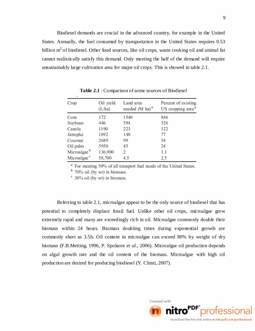
Biodiesel demands are crucial in the advanced country, for example in the United
States. Annually, the fuel consumed by transportation in the United States requires 0.53
billion m3 of biodiesel. Other food sources, like oil crops, waste cooking oil and animal fat
cannot realistically satisfy this demand. Only meeting the half of the demand will require
unsustainably large cultivation area for major oil crops. This is showed in table 2.1.
Table 2.1 : Comparison of some sources of Biodiesel
Referring to table 2.1, microalgae appear to be the only source of biodiesel that has
potential to completely displace fossil fuel. Unlike other oil crops, microalgae grow
extremely rapid and many are exceedingly rich in oil. Microalgae commonly double their
biomass within 24 hours. Biomass doubling times during exponential growth are
commonly short as 3.5h. Oil content in microalgae can exceed 80% by weight of dry
biomass (F.B.Metting, 1996, P. Spolaore et al., 2006). Microalgae oil production depends
on algal growth rate and the oil content of the biomass. Microalgae with high oil
production are desired for producing biodiesel (Y. Chisti, 2007).

10
2.3 Comparison of Raceways and Tubular Photobioreactors
Table 2.2: Comparison of raceway and photobioreactor methods
Table 2.2 compares photobioreactor and raceway methods of producing microalgal
biomass. This comparison is for an annual production level o f 100 t of biomass in both
cases. Both production methods consume an identical amount of carbon dioxide, if losses
to atmosphere are disregarded. The production methods in Table 2.2 are compared for
optimal combinations of biomass productivity and concentration that have been actually
achieved in large-scale photobioreactor and raceways. Photobioreactors provide much
greater yield per hectare compared with raceway ponds. This is because the volumetric
biomass productivity of photobioreactors is more than 13-fold greater in comparison with
11
raceway ponds. Both raceway and photobioreactor production methods are technically
feasible. Production facilities using photobioreactors and raceway units of dimensions
similar to those in Table 2.2 have indeed been used extensively in commercial operations
(Terry and Raymond, 1985; Molina Grima, 1999; Molina Grima et al., 1999; Tredici,
1999; Pulz, 2001; Lorenz and Cysewski, 2003; Spolaore et al., 2006).
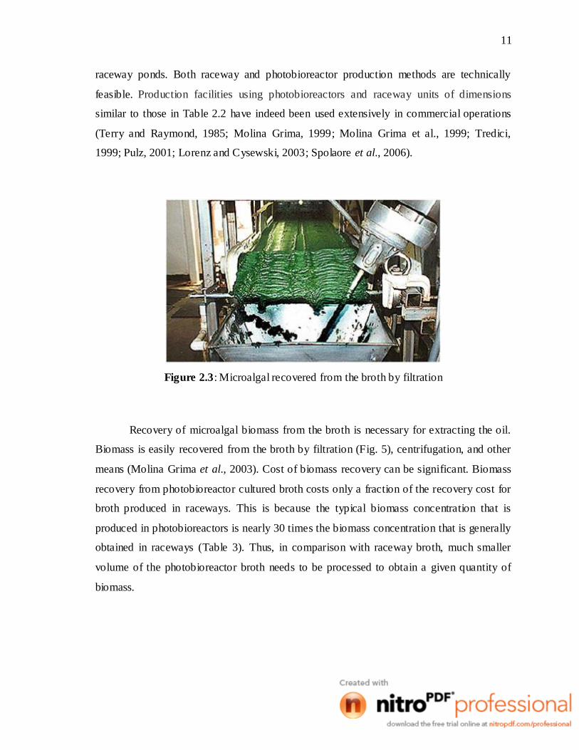
Figure 2.3: Microalgal recovered from the broth by filtration
Recovery of microalgal biomass from the broth is necessary for extracting the oil.
Biomass is easily recovered from the broth by filtration (Fig. 5), centrifugation, and other
means (Molina Grima et al., 2003). Cost of biomass recovery can be significant. Biomass
recovery from photobioreactor cultured broth costs only a fraction of the recovery cost for
broth produced in raceways. This is because the typical biomass concentration that is
produced in photobioreactors is nearly 30 times the biomass concentration that is generally
obtained in raceways (Table 3). Thus, in comparison with raceway broth, much smaller
volume of the photobioreactor broth needs to be processed to obtain a given quantity of
biomass.

12
2.4 Acceptability of Microalgal Biodiesel
For user acceptance, microalgal biodiesel will need to comply with existing
standards. In the United States the relevant standard is the ASTM Biodiesel Standard D
6751. In European Union, separate standards exist for biodiesel intended for vehicle use
(Standard EN 14214) and for use as heating oil (Standard EN 14213) (Knothe, 2006).
Microalgal oils differ from most vegetable oils in being quite rich in
polyunsaturated fatty acids with four or more double bonds (Belarbi et al., 2000). For
example, eicosapentaenoic acid (EPA, C20:5n-3; five double bonds) and docosahexaenoic
acid (DHA, C22:6n-3; six double bonds) occur commonly in algal oils. Fatty acids and
fatty acid methyl esters (FAME) with 4 and more double bonds are susceptible to
oxidation during storage and this reduces their acceptability for use in biodiesel. Some
vegetable oils also face this problem. For example, vegetable oils such as high oleic canola
oil contain large quantities of linoleic acid (C18:2n-6; 2-double bonds) and linolenic acid
(C18:3n-3; 3-double bonds). Although these fatty acids have much higher oxidative
stability compared with DHA and EPA, the European Standard EN 14214 limits linolenic
acid methyl ester content in biodiesel for vehicle use to 12% (mol).
No such limitation exists for biodiesel intended for use as heating oil, butacceptable
biodiesel must meet other criteria relating to the extent of total unsaturation of the oil.
Total unsaturation of an oil is indicated by its iodine value. Standards EN 14214 and EN
14213 require the iodine value of biodiesel to not exceed 120 and 130 g iodine/100 g
biodiesel, respectively. Furthermore, both the European biodiesel standards limit the
contents of FAME with four and more double bonds, to a maximum of 1% mol.

13
CHAPTER 3
METHODOLOGY
3.1 Introduction
In this section, we will discuss about the method that have been conducted during
the research. This section will be divided into three categories that is the design, followed
by construction and lastly the commissioning process.
3.2 Design of Airlift Photobioreactor
The design of airlift photobioreactor is considered of upper section and the bottom
section. The upper section is consists of liquid-gas separator and degassing column. The
bottom section is consists of series of parts that circulates to make the flow circulating in
the airlift photobioreactor. The design with its dimension is drawn by using AutoCad 2007
software.

14
3.3 Construction of Airlift Photobioreactor
The fabrication process of the bioreactor is done by the help of Mr. Hairul Hisham
from FKKSA. As the process involved cutting of , grinding and welding of metal and PVC
material, training are provided before the construction is started. The work is done under
supervision with the use of suitable personal protective equipment such as goggle, hand
gloves and ear protection. The process is divided into two phases, the building of support
structure and the building of the reactor.
3.3.1 Support Structure Construction
The support structure is build by using hollow carbon steel. The processes involve
cutting, grinding and welding of the steel to make the desired shape according to the PBR
structure. Stairs also have to build for the purpose of inserting water and nutrient from the
top of the PBR. Picture diagram of the process making of support structure of the PBR is
shown on Appendix A.
3.3.2 PBR Structure Construction
The material used in PBR construction is polyvinylchloride (PVC) plastic, consist
of transparent and non-transparent (grey) PVC. Fittings also used to connect the series of
pipe with diameter of 10 and 15cm. The fitting used are described as in Table 3.1. The
process for making the PBR is also described in picture diagram in Appendix A.

15
Table 3.1: Type and quantity of fitting used
3.4 Commissioning process of PBR
Commissioning process is used to evaluate whether the airlift PBR that has been
constructed is working. To proceed with the process, the blue dye is used. PBR was
connected to an air compressor with a pressure gauge to measure and control the pressure
of air sparged in the PBR. 50 ml of blue dye is placed in a Schott bottle. Using water pipe,
the PBR is filled with water until half of the degassing column is filled with water. The
outlet and the air inlet valve have to be closed before the water is poured in.

16
5ml of blue dye is taken from Schott bottle using a syringe. Then, by using a
hollow stainless steel rod, 5ml of blue dye is injected to the downcomer column. The air
compressor is set up and the pressure is set as 2 psi for the first trial. The valve of air inlet
is opened. Time for the blue dye to complete a cycle in the PBR is taken. The flow pattern
and dispersion of blue dye is observed. The water is drained from the PBR after the blue
dye has completely dispersed and the water is completely change color to blue. The
commissioning process is repeated for pressure of 4, 6 and 8 psi.