design guidelines for laboratory exhaust fans and …ventilation designers. when the laboratory...
TRANSCRIPT

AIVC 11909
CH-99-7-4
Design Guidelines for Laboratory Exhaust Fans and Stacks
Kenneth D'Cruz Member ASHRAE
ABSTRACT In this paper, design guidelines are presented for labora
tory exhaust fans and stacks based on the contractor's installed experience in the field.
INTRODUCTION The lifeline of every laboratory ventilation system is the
exhaust fan. With a working laboratory exhaust fan, removal of hazardous chemicals and biohazards in the building can be accomplished even after failure of the supply fan with sufficient infiltration. This paper presents tried and true design guidelines based on decades of maintenance and operating experience with hundreds of laboratory buildings.
REDUNDANCY AND RELIABILITY Although not usually required by local codes, the greatest
degree of reliability would be to place the laboratory exhaust fans on emergency power. If the exhaust fans are placed on emergency power, splitting the exhaust capacity into more fans with lower horsepower would mean a lower in-rush current as each fan is started.
Greater reliability is achieved by having each exhaust fan system consist of a minimum of two or more exhaust fans. This ensures that at least some exhaust capacity will be available if one fan fails. Maximum safety is achieved with 100% redundancy but at a large cost penalty. This redundancy would mean having the same number and size of backup fans as there were active fans. Sufficient reliability is often achieved by having N+ 1 redundancy, but also at a first cost penalty. For example, two fans operating and one standby would be N+ I redundancy. Four fans operating and one fan standby would
also be N + 1 redundancy. N + 1 redundancy allows one of the active fans to fail and still be completely backed up. However, two fans failing simultaneously would lead to reduced exhaust fan system capacity.
If 100% redundancy or N+ 1 redundancy imposes too large a first cost penalty, the recommended multiple fans on each system should be slightly oversized so that as much capacity is retained in the system as possible when one of the fans fails. This oversizing will also give some allowance for future expansion, which is quite common over time in laboratory exhaust systems. Having all fans in continuous operation avoids keeping bearings lubricated when on backup and on rotating fans.
If the exhaust fans are equipped with variable-frequency drives, the service factor of the fan motor can be used to overspeed the remaining fans after one of the fans has failed. However, care should be taken not to over-amp beyond the service factor of the drive, which is usually less than the service factor of the motor. (Rotation of lead and backup fans on a weekly basis helps keep fans in working order if the system is staged for 100% redundancy.)
INDIVIDUAL FAN PER LABORATORY HOOD VS. MANIFOLDING
The ANSl/AIHA Z9.5 committee (AIHA 1992) reached a consensus that manifolding fume hood exhausts was safer in almost every case when compared with one individual fan per laboratory hood because the manifolded system achieves greater dilution. An individual fan per fume hood is acceptable. However, with one fan per fume hood there is no exhaust if a fan fails and it is more costly to apply heat recovery or vari-
Kenneth D'Cruz is president of County Mechanical, Inc., San Diego, Calif.
THIS PREPRINT IS FOR DISCUSSION PURPOSES ONLY, FOR INCLUSION IN ASHAAE TRANSACTIONS 1999, V. 106, Pt. 1. Not to be ,_prtnted in whm. or in part without written permiseion of the American Society of Heating, Refrigerating and Air-Conditioning Engineers, Inc., 1791 Tullis Circle, NE, Atlanta, GA 30329. Opinion•, findlnga, conclu1ton1, or recommendations expreesed in thl.: paper are thos11 of tne author(s) and do not necesaart\y reflect the views of ASHRAt=. Wrilt9n questions and commentl regarding this paper ahould be received at ASHAAE no later than Februuy 13, 1999.
able-air-volume (VAV) controls. An individual fan per hood i also generally used for hazards requiring special filtration or decontamination procedures such as perchloric acid ;in(l it radioisotopes. - Perchloric acid and radioisotope hoods are general! y not candidates for heat recovery % variable-volume controls.
SELECiiNG LABORAiQfiY EXHAUS'i" FAN-VOLUMES AND STACK HEIGHT
Necessary measure must be taken to protect the laboratory _builillng and ·adjacen:t'"buildings from toxic fume blow-1 1 11 • Dack. Some state laws mandate a minimum 7 ft (2.13 m}labo-ratorj exhaust stacka�_9vefr.e roof. Tbi_s is primli.i'-"ily intended to protect mainten�uu;e workers from direct contamination from the top of the si;adc. ANSl/AIHA Standarp Z9.5 (AIHA 1992) calls for a 10 ft (3.05-m) laboratory exhaU'st stack for the same reason. However, these minimum heights'are not enough by themselves to guarantee that harmful contanrlnants will not he hlown hack into t�e huilding's outside air intakes.
lo addition, Standard ZIJ.5 recommends that exit veloci--ties..shoulcLnot-.doop.-below-3,-0.00-ftLmin.{15.24-mtsf-ot:-the
minimum exit velocity necessary to throw contaminants away irom the laooratory ana surrounamg oui1amgs. ,;t Chapter 15 of the 1997 ASHRAE Handbook-FundametF tals (ASHRAE 1997) describes the geometrii; fuethod'.• ThiS method is most appropriate for use by laboratory· b1,.1ilding ventilation designers. When the laboratory build�qg'c�oes not pass the geometric method of analysis, spcci�li�f don s� Itants
in airflow around buildings should be citltecf in. Thl:·se specialty consultants �an use wind tunnel modeling <?r oth�r computer or calculation methods to ensure that safe dilution levels h_ave been achieved in the laboratory exff�ust befor� iC impacts-any building outside air intakes or anyone's breathing zone.
TJ,13 1Ta.nmi::a......;� T"n.a.f-J.,,,....,,.l "�"'l;a..co +...,, T"a.ro+.-...,,ll'T,,1.-. .... h .... ;1A;...,11TC' .a. .1.1,...,. O '"'vu . .1....,.1..1..1.\.I .1...1..1....,.L.&.&'-'U u.pp.1..1.""'o "'-' .1.'-'""'Lu.i.1.eu.1.u.i uu.1..1.u.1..1.1.00
that do not have taller buildings, taller trees, or taller hills in the area adjacent to the laboratory building. Provided these-conditions !!!"��met, the g�nietric method can be applied as follows�
• C�:c,ulatc _the length of the recirculation zp�� downwind ofihe building.- 1
. _
Calculate the effective stack height due_ to throw and add., it to the fan �d stack height. '" ., Use a five-to-one downward slope for the stack plume from the height of the throw and make sure it does not impact any part of the downw.�nd recirculation zone.
I •-') ,, . , •'
r ' , ( . }_: ; ' �'. _ ., ) �I J Geometric Stack Selection Example
"' '..'1 •
A laboratory building is 100 ft wide, 200 ft long, and 60 ft high. The laborat�rf�"1lausf is'Iliianft'Oitled�rtte1a'two�iin{' system. Each �)� 10,qo9,.�fm (2..8.q(1�3(m)i 1]it{ Jwo-:fan system is Joc�te,<;l ii\��� q!IJ�rnf the roof. Calc11l�t�_tb� <;OQlPir-.,' nati�n o{.�tack nei�ht,.,yqiume� �[ y�)R�JtY::!:ha1 w,:il}, sati�f:y -
the ���#�'.-m��P4\·i!.. j,ji!; ! ··::;: · . _ •
�;p,ie length 9f tht:; r�sir�lllati,on. ?;QO,e i�r{V) ·f-fllJOws:T! ;fl •. •.
2
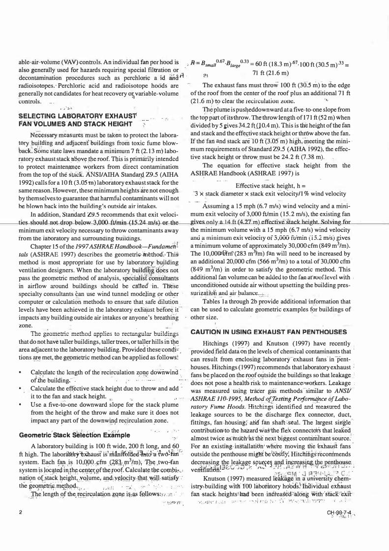
; R= Bsmau0·67·Biargeo33 = 60 ft (18.3 m)·67·100 ft (30.5 m)33 =
(>I 71 ft (21.6 m)
The exhaust fans must throw 100 ft (36:s m) to the edge of the roof from the center of the roof plus an additional 71 ft (21.6 m}t9 clear the recitculaliou zone. .,,
Tlie plume is pusl}eddownward at a five-to-one slope from the top part of its throw. Thctthrowclength of 171 ft (52 m) when divide<! by 5 gives 34.2 f't(l 0.4 m). This is the height of the fan and stack and the eff(:!c.tive stack height or throw above the fan. If the fan and stac1c aie-10 ft (3:05 m) high,:Weeting the minimum requirements of Standard Z9 .5 (AIHA 1992), the effective stack heigl}t or throw.roust be 24.2 ft (7.38 m).
The equation for effective stack height from the AS�RAE Handbook (ASHRAE 1997) is
Effective stack height, h = 3 x stack diameter x stack exit velocity/1 % wind velocity
Assuming a 15 mph (fi.7 m/s) wind velocity and a minimum exit velocity of 3,000 ft/min (15.2 mis), the existing fan gi'ves only. a 14 ft (417 m) effccti.ilcUhick heighLSol\ti.ng&J! ... a.,.r.__ ____ _
the minimum volume with a 15 mph (6.7 mis) wind velocity anu a minimum exh veiociry of 3,000 fu'min (i5.2 mis} gives a mi.nimum volume of approximately 30,000 cfm (849 m3/m). The 10,00@a-o1'(283 m3Ym) fan will need to be increased by an additional 20;000 cfm (566 m3/m) to a total of 30,000 cfm (849 m3/m) in order to satisfy the geometric method. This additional fan volume can be added Lo the fan.aL'rouElevel wilh unconditioned outside air without upsetting the building pres-surizaii'o11 and air balanct:_, _
... . - -__ - --l. ..
Tables 1 a through 2b provide additional 'information that can be used to calculate geometric examples f.�� buildings of other size.
CAUTIQN IN USlf'.,j.G EXHAUST FAN PENTHOUSES Hitchings (1997') and Knutson (1997) have recently
provided;field data on the levels of chemical contaminants that . can res�lt from enclosing laboratory-exhaust fans- in-penthouses. Hitchings (1997) recommends that laboratory exhaust : fans be placed on the roof outside the buildings so that leakag_e •
does not pose a health risk-to maintenance1wo�kers. Leakage •
was measured using tracer gas methods--sirriilar to ANSii ASHRAE 110-1995, Method'ofTesting Peifonn�h.ce bf Laboratory Fume Hoods. Hitching� identified a.11d'measured t..lie leakage sources to be the discharge flex connector, duct, fitti'ngs, fan.housing; atM fan shaft•seal. The largest single' contributiollito the hazard wa:ld:he flex connectdrii that leaked almost twice astmibh1ltsthe next biAAest contamiilant"source.' ·
For an existing· instrulatitln j wn:ere moving the hhaust fans outside the penthouse miglii be rcoshy; Hitching�recorrimends decrea.�it?;g th7 le�ag� spui:.�es _atl.d. i n.sn�a� · ng, the �en�o4se venidatliln�:3cC· .;;J , .-: , .... -1 }f� • 11•• N · :ct c..�"'. �11-:·· •
:· .. r- aH1 · ;.J P:l'-i'�,... . .. - c · Knutson (1997) measured fohlfage rn a umvers1ty chem-
istryi building with fOO litbotatory hobos� fooivl.aual exhaust fan .gtack heights!:had been imitea�ff�alcilig with,.sfaclf'exfr
-J� .• f.J".I\' I ,1�'1 :i1 ,. ,.. '.}i , .-'. () �. \ ·:'i Y'i'•< �:1.'�L .!')'']'"' !
CH-99-7-4 � · ·'JL-c<'1

TABLE 1a·" " . . ':'Jl
I·
;: Building Width or Length (ft)
. .
;l. Length of Downstream ReqircuJation Zone (ft)°
·
-•
L •
·' Number of Stories .. -,:,: ' ' ,, (Building Iikight) n:; . .
·' 1 Storyt 2�ries 3 Stories 4 Stories S Stories
.,, t j � � :
6 Stories
' iO>' • ·
7 Stories
t J
' J'.! ,,-, ' �' ·tis) : (30) (45) (60) (75) ,L!XJ),, �(lOS)J";;;.,: ::J ... . •'
so,,, 22.3 3S.5 46.6 S3.l i.!! S7.2 60.7 ..
63.9'': ... ... ?JIS I� I !)J-.1" ;; '
100 't (:\.1,: � 1
. ' lSO :
200 .!!
2SO \<•
300 ·' ·f:
soo J ·,1.
1000
I
• 11 '25.S I
28.('L'•
29.8 ' 29.8 ,:
29.8
29.8
29.8
29.8
.,l.;. 40.fr S3.3
44.6 S8.6
Sl 67
S6.10 73.6
S9.60 79.2
S9.6 s.4;� S9.6
°":.' ·:. 89.4
S9.6 89.4 " '
64.6 ,, 7S
71 82.S
81.2 ·,:f 94.3
89.3 ,, '103.7
9tfa. I
111.6 , ,
ip2 .. .,
118.S
·•,,1;19.2 140.3
119.2 . 149 . .
U1
..
, . . , . ' '
L 79.r
93.2
.,U)(i.5
; 'H 7'. l
J i:i6.1
133.9
1S8.S
178.8 'JI
•' '83.8 .I!
101.6 . . � �· .
118.1
129.9
139.8
148.S
17S.7
208.S
* Formula for table is: length of downstream recirculatkm zone is BsA0.67 *BLA0.33 .. "l'here Bs is smaller of height and width or leqgth and BL is the !wger of the two (ASHRAE 1997). Where BL is> 8 Bs, use BL= 8Bs. t Each.story is 15,�higb. ·'" ' •:·, •'
' ,r
Building Width.or Length (m) :; .
11,
. :• �'· , ,, ,,TABLE 1� , ,. Length of: DGwnstream Recircul�tion Zone (mf
'·
I'· • • {I •
Number. of Stories . 1(iiuil'dTug Height)
- ' l ' ,.
. ,1 Storyt,�, �Stories 3 Stori�· . :4 Stqries 5 Stories 6 Stories • 7 Stories . .
(4.57) ' (�.)4). (13.7), (18.3) (23) (27.4) (32) lS.2 6.8.: 10.8 14.21°. 16.2 17.4 "18.5 19.S ,, .. . . !
[(�2.9 . I "
fo.7 .-J I � : .. ,
7.8 .. 12.4 16.2 22.9 24.3 ,2S.S -
30.S 8.6 13.6 17.9 21.6 2S.1 28.4 31
: 4S .. 7 - 9rt·· .. lS.6 20.41 L 24.7 28.7 .' 32.5 . , . ... :; 36
«H17.1 22.�li 27.'2 -
61 9.J... 31.6 3S.7 39.6 ' " ' . ·' .. '
J�L ·'76.2 . � l .. 9j1· 18.i' 24.2 1r1 29.3 34 . . 38,f,� ': : ) t4U},. " ,, Ji .. "J
91.4 •. 9.1 \ is.?. ,,. , ; 2S.7 31.1 36.1 40.8 4S.3 <• ' - ':: •h- ' .. .. ,1 l: • " ·1".1• "'' 1S2.4 ,,'. )�iJ • !�119,1 ·''1· .. 18.2·1 27.2 36.3 42.8 48.3 SM '
� ·,, l •: 1 8.i: . ,304!8' T . . ,. 9.1 " 27.2 36.3 1. 4S.4 S4.�. 63.6 . . " '
, . .. ' ;,.,if 11. ,, ,,G •
* Formula for tably. is.: length of do'l""strea� .r\'9fculati;n zqne i.s Bs'�0.6� *.Bl.l-A0,33 where Bs is smaller of height and width or length and BL is the larger of the two (ASHRAE 1997). W!lere BL is> & Bs, use BL =·BBs. . .. , •• '.'
' . t Each story. js 4.57 m higb. . ·: ·1 "·�, "• · 1
•
!1 : . LI!' :'J •. '!
'11
' ,
' ve,lq�ities in f!-,remode�g;projee;�. lY,Iitigation recommenda- .. tion�}nclude9�11creasing piwtho�s,e,g�neralyentilati.on to 8;iir _.
changes per l)qw,. replacing du�t vvith w�ld�ai,rt;�ght duct,· and replacii;i,�:. fie� .poqnec\C)rs. T�. c;lp¢ fie� COlllJector ?Was . replac�� with,�f���ible1�0JG� ru1?:1J�r boot, " ·· .
tion but are 'hazardm:i8'.'bec�use they direct tb'b contaminated flow
kdown at the roof'.�rJ.�e i\b�A,�eer
.t�eiaintenance
wor ers. lr .. ; ::; 1_ (:i: /+ �:Ji: J , 1, I,. :.G ,(\
PL�NU.1)11 INl;.Eif ,f,QR l\(\ULTIPL-E:·F�Ns,, •d
'
cAuno�s'wrrii'wi:Ani�RtAJ>s;'�6os·E�i#Rs�··:; AND FLAPPER DAMPERS ; f'" i ·. '.J; .·wn: -�:��c,· \:n;· _,,I'. .1 . . : .t· :·1· '�.)l!.i.:·�: .·:i ljl;o::t:.�·r
: ,uJl;i�, .. 19..9� .. iA_[ilfl?tAK Handbook-,HYAC·. Applications:! strgng!y,��cqiµw.t:n�s f}ga.i11st tbt:J :use of -weather;caps, •goose,..' necks, or flapper dampers. These devices provide rain protec-
r:. For relialfility(t:mrpclses, 'laobrafbry exhaust fans should ha\r.,twe or:m�re nihltiple fitns bn eai::h'fume lrddd Illl:l.Ilifold. ', These multiple>fans' lidul'd'liave· a plenum "inlet railiet' than ·a: .. ducted inlet. This plenum inlet will help· e·rt�Ute-iliarth'e fans·!' will hav�the Sartie inlef�tfadltiGns so'that ffl�y·ean tie bafah� properly.
. ,-, CH-9i:b-4'-· 3
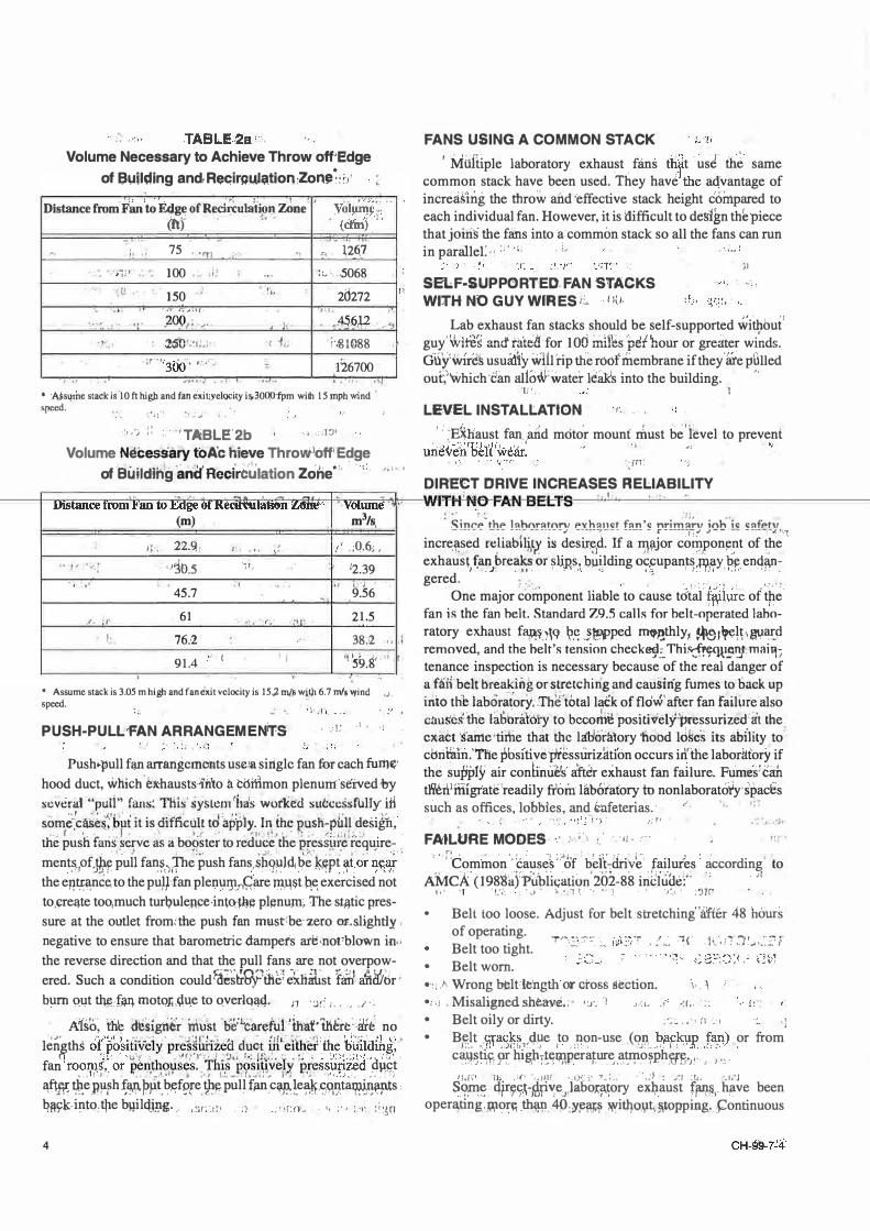
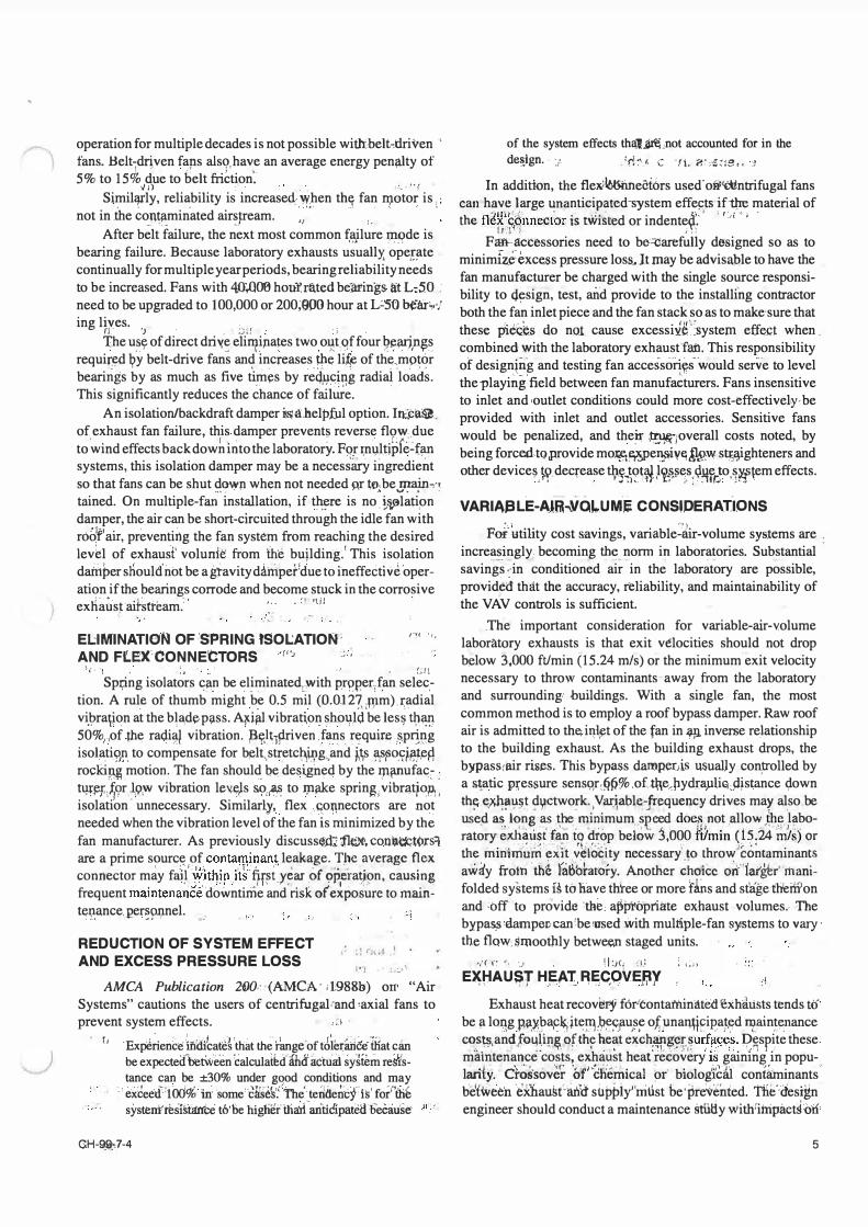
Volume Necessary to Achieve Throw off;Edge of Suilding and,Recir�u.J�tion :Zon� �.: '>'
• ; J I . � ' t"� ,:. • I � ' Distance from Fan to Edge of Recirculation Zone
(ft) . , �.
Voi���� .. • (crin') '·I
l I
o .
75
100 . . :• 150 . ..!
:uiiO .:1 •• ;
'•·
)(
.. 12(\7
;l.; ,5068
20272 "I '· ,.4-56µ . 'J
f',81.088
126700 ·�
* :A$s11ihe stack is ·10 ft high and fan e'xitryeloci�y is.30CJP·fpm with 15 mph .wind ·
speed. -. ; � J ! ��� _· ......
: .. ·; :: . .,TABLE'2b ·' · '1'.J'
Volume N'ei::es'sary t'6 ·A'c flieve ThroW1off'Edge of EiuildMg 'and' R'edrb'�lation Zone·'
· ·
ti
FANS USING A COMMON STACK ' Milfiiple laboratory exhaust . fans thf t · usl tlub same
common stack have been used. They have the advantage of increa'�'ing the throw afid 'effective stack height c6inpared to each individual fan. However, it is liifficult to de�ign th� piece that joiri� the fans into a common stack so all the fans can run in parallel'." : ; ' ' · ;_. · .,, ·
SELF-SUPPORTED. FAN STACKS WITH NO GUY WrRES i.� · t 1u.
)I
Lab exhaust fan stacks should be self-supported wi19out' guy!WtteS �11cf��telt-for 106 irJ.�ds··pethour or greater winds. di.iYwrr�� usuid.iy wH1 rip tlie roof' membrane if they'iite pHnect out�''Which,can alio*:water leaks into the building. •·
·11•,, 1
LEVEL INSTALLATION ' .
· :E�haust fan artd mot�r mount rimst b�' h!vel to prevent · ' "·ri �J · r · · · " uneven r::ieh'welir. ,, ' "'
. ·v
,rn:
DIRECT DRIVE INCREASES RELIABILITY �� 1-.....-===-=c-�'"��-.';l..��·-r-I',�-�·�·...e-,-,.ri-� �+-...,.,.,.,=-"� �-----Wf� ��....ea. N ..a E l...!l"�,...------.-...�1.������������� DiStarice from F'an to fuige 61 Kecu�ualiftn Lane·· · vmwne · ,
. ., n n u r.H. u L.1 � (m) m3/s,
Jl . 22.9. ;� f' ;Q.6,, ,
� .- ; •)10.5 1L 12.39 ,. .. . ... r:·;
45.7 9.56
�- I 61 '" '• ·1.1� 21.5
J· 76 .·2 38:2 "
91.4 r I • J '1�9.S' ,,
* Assume stack is 3.05 m high and fan exit velocity is 15.,2 m/� wit)l 6.7 mis wind ,J speed.
PUSH-PULL-FAN ARRANGEMEITTS \ ·_: 1 � , � '
I ' I
Push•pull fan arrangements useJa single fan fur each fum�· hood duct, which bX:hausts'ib'to a coffimon plenum served by sevdral ."pull" fans: THis' systemftH\s wofk�d sul:.cessfully Hi som�:ca�e �·b�i it is _diffi'cul.t td 'aifply. In:fhe pusn-pfat desi�b, ( I • I t ., ' 'I• . ,.J �· I' ,, • � . the push fans' serve as a booster to reduce tlie pressii�e'require-
' -.� ,.JI l '> • •• • .,..- ' , · · \ ment�,pf:Jb.� pull fan,�,);fbe push fans,�h9pld1 be ��pt �t or %¥ the ent,ra;nc�to the pu�Jfan plem,11J1_,-,�are Jl1Rl)t P,� exercised not to,�re�te too, much turl;mlem.:e intQ-l:lJ� pl�nuro. The st�tic pressure at the outlet from;the push fan must:be"zero C>Lslightly, negative to ensure that barometric dampers ate'not'blown in,, the reverse direction and that the pull fans are not overpowered. Such a condition could ���h-9:Pffi6'l �Vt�st fifi1 afiAftir · bum qut tly:,f-illl motoJi ,(jiue to o_verl�a4. n · �r: 1, • •• • ,. · ,
A.1sll� th'e d�ignt{r H�· t :obfs6aref'ti1 'iha�·tli�re:'itt� no l�i'lf,ths cj('p�Jsi_Hy�iy · p��i��ie� cfu�t �·.�i�et '�� ,bti��aihg,; ' fan !roorp,s\" or" pe�tho,9;�5'. . "nu¥'P,9s1�v'el,Y 'i>ies s��d '(Iµ�t
..... ·) • • �I _, • "" .•.1 t ... ... . . 1, .... r. ... r.. , , ·
, ·· . . , . _ . ,. : . ! a,f'W �e _p}lph �1!>1)1.-PJ.lt, b,f1f�[e tpfpull f � .c� !e�·S9Ata.JP.j,�ii.p.ts , b!ls;k,into:tjie b�ilqjpg. ,:ir;oi:·! :! :·•r:n, . ,, : , >•: �''.�rJ
4
• •• " ;'fj_.', ,.i
.c;;inrP thP l:ih"r"t"r" Pvh,.not f,.n'o nrim"r" i"h io o,.fPhr �----- --- - -�------ --_, ---,---�---- ----- - r-----�f!:" J-- - -----.,-.1.7\1
incre��ed reliab1rt1 i� desir�1d. If a ��jor col!lpon!'!_?t of the exhaust) ���_,bre�� or �U,ns.1 bµ�lding Offupan��ol1?>�y p�. enqwi� gered. ,' . ,_ . ., ,, . . .. . . ,
One major con:iponent liable to cause total" iwiure of tpe fan is the fan belt. Standard Z9.5 calls for belt-operated laboratory exhaust fapfuN �-� J�ped rrnmthly1 �1�lt;81Jru.:fi removed, and the helt's tension check�;-Thi�<Jll!l'.1J� miiiri1 tenance inspection is necessary because of the real danger of a faH.belt" breaking or stretching and cau�ing fume to back up into th laboratory:'Th�total lack offlo-w'afterfan fruli.ire also clmS'es�the fab · ia ·ory 'fo becortll! positivelfpressurizea iit the e�aer ·. aine •tiI\le that l:hc Iii cira\ory 'nobd !cl es its ability to·: cbrithln.''t'he pbsiiiveffeessurizatfon occurs inilie labodttory if the �upply air conlinues aft�r exhaust fan failure. Fumes: can t11'enlffiigrate 'readily filorn Hlb6tafory to nonlaboratofy' s'pac'es such as offices, lobbies, and tafeterias.. ; . ,, .
1;rr .·: ; �J
FAtLURE MODES ' _, ·' ' ! . If 0 ,, -·
-- .-. r.1 , . ,· . , • . - ... , i, : r , • .- - , . , ·- t , •
. ''common-;eauses' of bdtcdrive failures according' to , . .. , , . . .-1-.· ·. � , - , _1 ·p T • ' : I ' r·. ! • . • f AM:cA (198'8a)P�bfa;atiUn 202-88 inchiile:'· ; · '
f•' 'l '!.';._ · .' '.,,> 0 ),_'.:·1 '· ._. '' ·1 · ' "<1 · :'51P .
• Belt too loose. Adjust for belt stretching''iiiftfa 48 h&urs of operating. f··��:;:::'.·�:_�; __ £�.it3 .. ? . ;�.,.� ·-1r .-h. dT,1 �� ,.:: ::: r Belt too tight.
• Belt worn . •·:: /'· Wrong belt:le'ngth or cross section. 1·. 1 •. ; , Misalignedshewie.;· •:.r.: ') J.'l, ,, ·:r •. :: • Belt oily or dirty. :·: c,. ·, a -�·' • B�lt .i;;rac�� ,qµe _to .non-use (q1,1 b�c�p _ f3.11) .1,�.· � -'· ,,J(,(�1 . . _J I ;_,.• , .) , .�-''- ,,, _,.,,, ( ,.}• •
c<1:9�t�r· 9r �ig,b,��w,peraJ:ur�.a,t_rp.o�ph�i;,;:· , ) .. .
·' ., or from
n.ff' Th _;c ;.iH". ·-O(�' -r_:.. · ·,�-� : /1 :tl. ·.1;_,J S9��- 4r-7.9�ch\r'je)abo,qi,�ory exJ:iaust ff!%. h11ve been opera};ing:wor� th.iffi. 4P,¥�� W,itl}.o,yt1�t9pping_. �ontinuous
operation for multiple decades is not possible witlr.,belt-,tlriven ' fans. Helt�dtjven fap.s als9,have an average energy penalty of 5% to 15% due to belt friction�
vi) . •· .. ·,. r Similiµ-ly, reliability is increased w.hen thtt fan II).otor is . ;
not in .the contaminated airstream. ' '" ,., ' ' , .
�: <- ,) lJ ; •
After belt failure, the next most common failure mode is 1.1-.A : - .. ·,
bearing failure. Because laboratory exhausts usuallY, open1te continually for multiple year periods, bearing reliability needs to be increased. Fans with 40:,000 houl'. r0.ted bearings at L�50 .·
need to be upgraded to 100,000 or 200;900 hour at L�so bear':•'/ ing l}�es. 'J .
. ;},! , .
The u�y of direct driv,� eli1¥i,iates twooi,�t 9f four 9�!1D.P�8. required �Y belt-drive fans and increases µie li� of the.motor bearirigs by as much as five tim�s by reCiucing radiai '1oad�. This significantly reduces the �hance of f�i��-
.
An isolation/backdraft damper �a.helpful option. lt£cMJ. of. exhaust fan failure, this damper prevents reverse flow due to wind effects back dowh l.rito the laboratory. For i;nultipfe�f� systems, this isolation damper may be a necessary iD.gredient so that fans can be shut dowp. when not needed AT to.be main-n tained. On multiple-fa�" installation, if t��re is no
• t��ti.on
.
damper, the air can be short-circuited through the idle fan with roof' air, preventing the fan system from reaching the desired lev�l of exhaust' volun1e from the bu�lding� 1 This isolation datitper s�ould' not be a gtavity d�niperdue to ineffectivd'operation if the bearings corrode and become stuck in the corrosive ex�aost aihtream.' ' -·�" •\il
EL:1MINATION OF:S'PRING tSOL.:ATIOl'\1; 1�' '"
AND Ft.EX:CONNECTORS ·'f"" ·· • \.-i • '! ' ..J ' �.; 11
Spi;ing isolators C;ln be diminated1with pr�per!fan selec.-tion. A rul.e of thumb might b_e 0.5 mil (0.012?, ,11,1m) r,adial vi,'\>ra�jon at the b�iid� pt;J.ss. AJ<.iftl vibra�on sho�.ld be less �� 50%,,of me radiaj vibration. ;s�(lti�riven Jans requir,e ,s.pr!�g isolati9p, to compensate for belt"stretc�g,and ��s ¥�0.9��eP, rockip� motion. The fan should. be designed by the rpilllufac� . tqriet:�9r .. �9:W vibration le\:'.els SO,r2;8 to iµitlce sprin�1vibr4t�op., isolation· unnecessary. Similarly, . flex 1<onnectors are not needed when the vibration level �f the fan is ·�nimized by th� fan manufacturer. As previously discuss�.d; 1'le)ll, con•e1Gt(lrs1 are a prime s?urc� ,of conta�inant lea;I<age. T.he ave�agc flex connector may fai�' J'Vitryip} tk f}pt .y�ar _of'9fy:ra9.on, causing frequent maintenance downtime and risK. ot'exposure to main-te-11:ance. per�p.i:inel. _ , , 1
REDUCTION OF SYSTEM EFFECT AND EXCESS PRESSURE LOSS
I • I � I !� • f I
·1
AMCA Publication 2110-� (AMCA · 11988b) on• "Air Systems" cautions the users of centrifugal rand 'axial fans to prevent system effects. ,:1 ·
f J 'Exikrlen�e lncffcate1 'th�t th� r�ge ·or t6Ieriul&: hlat ciin be expecteifbet\v'een �alculatbcf ahd' achlal system reifistance can be ±30% under gqod conditions and may
'.: exceed-: :1 Od% in some' clr'Sek( The terlde�cf is' for'�Oib systeni'ri!sifu'.tfce t6'be higiiedliaii aiftiCipatdlbecause
CH-�,.:o?-4
of the system effects th�l.Untnot accounted for in the de!!_ign. '/ . :fl:'« C !J,. ?,: ,£�;e.,, cl
In addition, the flex'l6tsnneciors used'ofil'{:ijntrifugal fans can-have large �anticipated-system effe�ts·if� material of the fl�f�annector is tv.listed or indente«. · ''" '' t I.I l .; ' '
Fm·a:ccessories need to be�arefully designed so as to minimfz.e:exce.ss pressure loss�Jt may be advisable to have the fan manufacturer be charged with the single source responsibility to cj,�s-ign, test, and provide to the installing contractor both the fan inlet piece and the fan stack so as to make·sure that these p1ec�s do nol cause excesshUr'.system effe�t when. combined with the laboratory exhaust fan. This responsibility of designing and testing fan accessc)ri�-would serVe to level theplayi�g,field between fan manufa�turers. Fans insensitive to inlet and •outlet conditions could more cost-effectively-be provided with inlet and outlet accessories. Sensitive fans would be penalized, and their �-roverall costs noted, by being forced.to provide mo�'ilSPe�iv�!,W:w sn;,�ghteners and other device�J?.deqease tJ;ig-:�?Wl ;l�,�:;�s:1:lfft·}o.��tem effects.
. . ' . VARIA.BLE-A.UihVOL.UMi CONSIDERATIONS
Foi�tility cost savings, variable�iiir-volume systems are . increa�!_lgly; becomin_g t!1�. norm i!l laboratories. Substantial savings �in conditioned air in the laboratory are possible, provided that the accuracy, reliability, and maintainability of the VAV controls is sufficient.
The important consideration for variable-air-volume laboratory exhausts is that exit velocities should not drop b�low 3,000 ft/min (15.24 mis) or the minimum exit velocity necessary to throw contaminants away from the laboratory and surrounding: buildings. With a single fan, the most common method is to employ a roof bypass damper. Raw roof air is admitted to the.i11l�t of the fan in WI inverse relationship to the building exhaust. As the building exhaust drops, the bypasscair rises. This bypass dampeds usually conp-olled by a st;atic p�essure sensqr:�f1%,oft\\eJ1ydi:a)lliq�pjs�nce �own t11!1 �JffiflU!i� dyctwork-iVatjable�-:,J!�quel}Cy drives may also.be use.d a�. long as �e �inimum s eed do� not .allow .Vi�. l�boratory eiui�tl�� fa_n t� �op below 3,000 Wmin (1?;24 mis) l?r the 'minimum �xit v�locity necessary' to throwicontaminants awiiy froth . the fatfotar0ry. Ai:lother cho'ice o�"1atghr' 'manifolded systems iS to have thtee or more fibs and stagetheiWon and :off to provide the a�pi'opriate exhaust volumes.· The bypas,s'damptmcan'be•used with multiple-fan systems to vary' tb.e t1QW $mootbly betwee.n staged units.
�/( C ..-, '�I ll :Jc JJ � i�J.I
E�t'AU�ff H;AT} �E;q9ve�y !
Exhaust heat recov�ry fol"eontaminated exhdtists tends to be a lo:qg P.il:�?��it�m:9��)au,s!! o�unarqtpi�at�d �n�(:llance c�s.�anj oq�in�.9f thr ���.t exc�iW�f� .
• �urf���s. D,�spite these
mamtenance costs, exhaust heatrecovery is gaining in popu-lfil-i y. dti�·s(;��� b'f1"cfieniical ·or biologtcfil contiumnants be{wee'n ·�:Xhaus6in1d siippiy'rriti.st be·pre:Y�nted. Tiie'·Cies�n engineer should conduct a maintenance stiitly withriiripact� on•
5

first cost, energy cost, and operating cost to confirm the feasibility of using a recovery system.
SOUND CONSIDERATIONS
The high outlet velocities recommended by Standard Z9.5 (AIHA 1 992) to blast toxic fumes away from the roof can cause high noise ieveis. However, unitized iniet and outlet silencers can be used on laboratory exhaust fans with little impact on the total system cost. While some engineers have specified packless silencers due to possible erosion of fiberglass, the units have a tendency to be costly and large in size. Therefore, they should be considered for use only where the installation location would be difficult to access for eventual replacement. Where silencers can be placed before and after the fan on the roof, the less costly packed silencers with caustic
and weather resistant liners are recommended. Acoustical louvers on the bypass dampers may also be required. As a rule of thumb, the silencer should approximate the motor cost on a replacement basis and should be readily accessible for changeout.
DUCTWORK MATERIALS AND CONSTRUCTION
The scope of this paper does not allow space to discuss all the material and construction choices suitable for laboratory exhaust ductwork. Careful evaluation of the corrosive materials to be transported, their concentration, and temperature must be made by the owner and design engineer. The most commonly found duct material is type-3 1 6L stainless steel with all welded construction. For some chemicals, stainless steel does not have good resistance. Many designers have used a galvanized duct coated inside and out with 4 mil (0. 1 02 mm) of PVC. Ductwork that is concealed in risers or otherwise inaccessible should have more corrosion resistance because of the difficulty of repiacing it. Where first cost budgets are tight, ductwork exposed on the roof or easily accessible may be made of less costly materials because of the ease of replacement. In manifolded systems, because of the large amount of dilution, some designers have even used galvanized duct with well-mated flanges for the exposed roof ducts.
6
CONCLUSIONS The design guidelines formed from practical experience
for laboratory exhaust fans are as follows: • Make sure that stack height and effective stack height
combined are sufficient to carry hazardous fumes away from the building.
• Place laboratory exhaust fans on the roof outside of any penthouses.
• If exhaust fans cannot be placed outside penthouses, increase ventilation. Also, reduce leakage by improving flex connectors and minimizing leakage from ducts, fittings, and shaft seals.
• Use direct-drive fans, longer-life fan and motor bearings, and low vibration fans.
REFERENCES AIHA. 1 992. ANSI/A/HA Z9.5, American national standard
for laboratory ventilation. Fairfax, Va.: American Industrial Hygiene Association.
AMCA. l 988a. AMCA publication 202-88. Chicago, Ill.: Air Moving and Control Association.
AMCA. l 988b. AMCA publication 200-88, Air systems. Chicago, Ill . : Air Moving and Control Assoc.
ANSl/ASHRAE. 1985. ANSl/ASHRAE 110-1995, Method of testin!{ performance of laboratory fume hoods . Atlanta: American Society of Heating, Refrigerating and AirConditioning Engineers, Inc.
ASHRAE. 1 995 . 1995 ASHRAE handbook-HVA C applica� tions, Chapter 1 4. Atlanta: American Society of Heating, Refrigerating and Air-Conditioning Engineers, Inc.
ASHRAE. 1 997. 1997 ASHRAE handbook-Fundamentals. Atlanta: American Society of Heating, Refrigerating and Air-Conditioning Engineers, Inc.
Hitchings, D.T. 1997. Laboratory fume hood and exhaust fan penthouse exposure risk analysis using the ANSI/ ASHRAE 1 1 0- 1995 and other tracer gas methods. ASHRAE Transactions 103(2): 863-872.
Knutson, G W. 1 997. Potential exposure to airborne contamination in fan penthouses. ASHRAE Transactions 1 03(2): 873-878.
CH-99-7-4