design guidelines for the strengthening of existing ... papers...design guidelines for the...
TRANSCRIPT
481
SP-230—28
Design Guidelines for the Strengtheningof Existing Structures with FRP in Italy
by L. Ascione, A. Benedetti, R. Frassine, G. Manfredi,G. Monti, A. Nanni, C. Poggi, and E. Sacco
Synopsis:Synopsis:Synopsis:Synopsis:Synopsis: A regulatory document was issued by the National Research Council (CNR) ofItaly on the use of FRP for strengthening structures: ‘Instructions for Design, Executionand Control of Strengthening Interventions by Means of Fibre-reinforced Composites’(2004). Emphasis is also given to specific requirements for seismic applications.
This document, described in more details in the paper, sets for the first time in Italysome standards for production, design and application of FRP for reinforced concreteand masonry constructions. It is also conceived with an informative and educationalspirit, which is crucial for the dissemination, in the professional sphere, of themechanical and technological knowledge needed for an aware and competent use ofsuch materials.
The document is the result of a remarkable joint effort of almost all professors andresearchers involved in this emerging and promising field, from 15 universities, of thetechnical managers of major production and application companies, and of therepresentatives of public and private companies that use FRP for strengtheningartifacts. Thus, the resulting FRP code naturally incorporates the experience andknowledge gained in ten years of studies, researches and applications of FRP in Italy.
Keywords: design guidelines; fiber-reinforced polymers; masonrystructures; reinforced concrete structures; seismic strengthening

482 Ascione et al.Luigi Ascione is Full Professor of Structural Mechanics at the University of Salerno,
Italy. His research activities have covered various aspects in the mechanics of structures
and materials such as stability and post-critical behaviour of elastic structures,
experimental analysis of materials and structures, mechanics with unilateral constraints,
composite materials and structures. He is the general co-ordinator of the Task Group that
prepared the regulatory document CNR-DT 200/2004.
Andrea Benedetti is Professor of Special Structural Problems at the University of
Bologna, Italy. His research activity is focused on problems where the non linear
behaviour of materials is essential: masonry, concrete, externally bonded FRP
reinforcement, and fire damage assessment. His work is contained in more than 80
publications.
Roberto Frassine is Full Professor of Material Science at the Politecnico of Milan,
Italy. He received his PhD in Materials Engineering in 1989 and is currently Associate
Professor in Polymers and Composites Materials at the Politecnico of Milano (Italy). His
research activities are in the fields of viscoelastic properties, time-dependent yield and
fracture, processing-structure and structure-properties relationships and impact, fatigue
and dynamic fracture of polymers and composites.
Gaetano Manfredi is Full Professor of Structural Engineering at the University of
Naples “Federico II”, Italy. He is member of fib WG 7.1 “Seismic Commission –
Assessment of Existing Structures”, WG 7.2 “Seismic Commission – Displacement
Based Design” and WG 9.3 “FRP Reinforcement”. His research interests include
earthquake engineering and the use of advanced composites in civil structures.
Giorgio Monti is Full Professor of Structural Engineering at the University “La
Sapienza” of Rome. He is member of the Commission Design of fib (fédération
internationale du béton), in the groups “Seismic Concrete Design”, “Computer-based
Modelling and Design” and “Design of Structures Reinforced by FRP”. His research
interests span from reliability to the assessment and retrofitting of existing structures in
seismic zones.
Antonio Nanni, FACI, is the V & M Jones Professor of Civil Engineering at the
University of Missouri – Rolla, Rolla, MO and Professor of Structural Engineering at the
University of Naples Federico II, Naples, Italy. He was the founding Chair of ACI
Committee 440, Fiber Reinforced Polymer Reinforcement, and is the Chair of ACI
Committee 437, Strength Evaluation of Existing Concrete Structures.
Carlo Poggi is Full Professor of Structural Engineering at the Department of Structural
Engineering of Politecnico of Milano. His research activities have covered various
aspects in the mechanics of structures and materials such as stability of structures, plastic
collapse of structures, mechanical properties of composite materials and composite
structures for aerospace, marine and civil applications.
FRPRCS-7 483Elio Sacco is Full Professor of Structural Mechanics at the University of Cassino, Italy.
His research activity is focused on problems of fracture mechanics, of constitutive
equations for masonry and for shape memory alloys, and of non-linear structural analysis
by FEM.
INTRODUCTION
The peculiar situation of Italy with regards to the preservation of existing
constructions results from the combination of two aspects: a) seismic hazard over the
whole of the national territory, recently refined by a new seismic zonation, with
medium-high intensity over a large portion of it, the highest expected PGA being 0.35g
for a 475 years return period, and b) extreme variety of the built environment, perhaps
with no comparison in the entire world.
Construction typology in Italy encompasses examples reckoned as Country’s (and
world’s) historical, architectural and cultural heritage – which include buildings of
various function and importance, such as palaces, temples, churches, cloisters, theatres,
thermae, memorials, city walls, castles, simple dwellings, civil engineering works as
bridges harbours and aqueducts – dating back to more than 2000 years ago, throughout
the ancient- middle- modern- and contemporary ages, down to those built in the 20th
century. The former are largely made of masonry, although under this name again a great
quantity of techniques and materials are indicated, from those using stone of various
natures, squared or not, regularly placed or loose, or clay bricks of different quality, or
combinations of them, and binders extremely different in nature, in application ways and
in ageing conditions. Instead, the latter mainly consist of reinforced concrete
constructions, if not uniform, at least more homogeneous. This has motivated the growth
of two clearly distinct fields of research and application of fiber-reinforced polymers
(FRP): one for (generally old) masonry and one for (relatively recent) reinforced
concrete constructions. The first one is more peculiar, apart the complexity of the
subject, as masonry constructions have less alternatives of strengthening means and have
received less applications and studies.
It goes without saying that for the historical, cultural and architectural heritage, the
issue of structural safety is only one aspect of the wider concepts of restoration,
preservation and conservation. In this respect, it should be underlined that these concepts
do not allow a systematic use of innovative materials, such as FRP, for strengthening
purposes, unless it is demonstrated that they comply with the strict requirements
regarding formal and material compatibility. These essential considerations have such
complex and articulated implications that they would deserve deeper consideration that
is beyond the scope of this paper.
With the distinction in the two above described main fields of research on FRP,
namely, masonry and reinforced concrete, the first studies have started in the early 90’s
by some pioneering groups that were striving at finding new solutions for increasing the
safety of existing constructions, that could compete with the more developed and usual
ones of concrete jacketing, steel plating, base isolation, and dissipative bracings.

484 Ascione et al.In the last ten years the interest has spread so widely and rapidly that now FRP has
become one of the most active and prolific research fields throughout the country. The
most important testimony of the intense activity in Italy in the field of FRP is the
recently issued regulatory document CNR-DT 200/2004 [1]: ‘Instructions for Design,
Execution and Control of Strengthening Interventions by Means of Fibre-reinforced
Composites’ (2004), under the auspices of the Research National Council (CNR).
THE NEW FRP CODE IN ITALY
The CNR-DT 200/2004: ‘Instructions for Design, Execution and Control of
Strengthening Interventions by Means of Fibre-reinforced Composites’ (2004) is
composed of the following chapters:
• Materials (with Annex),
• Basic concepts of FRP strengthening and special problems,
• Strengthening of reinforced concrete and prestressed concrete structures,
• Strengthening of masonry structures.
Materials
The chapter on materials has a prevailing informative character and contains the
fundamental information needed to obtain a basic knowledge of the composite materials,
of their components (fibres, matrices, and adhesives) and of their physical and
mechanical properties. It also includes an annex describing the most usual production
techniques and some basic notions on the mechanical behavior of composites.
The most notable aspect is that a possible classification of composites usually
adopted for structural strengthening is proposed, and some appropriate criteria for
product qualification and acceptance are introduced. Moreover, the concept is introduced
of FRP as a strengthening system, enforcing all applicators to sell fiber-reinforced
material and bonding agent as a certified package.
It is widely recognised that the design of a FRP strengthening system is a critical
process. The various components (fibers, resin and the support) have different
mechanical properties and roles but must be selected and designed to work together in a
unique system. Therefore the properties of the components, their interactions and the
properties of the final FRP must be well known and defined. The chapter on materials
provides both general information on the mechanical, physical and chemical properties
of FRP materials and indications for the qualification of the components and the systems
on use in the reinforcement of civil engineering structures.
Specific sections of the chapter are dedicated to the main components, namely the
fibers and the textiles, the resin and the adhesives. For each of them the main
properties are discussed and some examples of the technical data sheets that should be
provided with the products are reported. For all the mechanical, physical and chemical
properties that must be determined or verified, reference is made to the appropriate
testing procedures and the relevant European and American standards. The terms and

FRPRCS-7 485quantities that are commonly used in the textile or chemical fields and are not familiar to
civil engineers are properly explained.
An informative section is dedicated to the different reinforcing systems. The main
aim is to clarify that the material properties can be referred to the total cross-sectional
area for the prefabricated strips. On the contrary when in-situ resin impregnated systems
are used, the final FRP thickness varies with the amount of resin and cannot be known in
advance. For this reason the calculations may be based on the properties of the bare
fibers but a reduction factor should be included to account for the efficiency of the
system and for other detrimental variables such as the textile architecture or possible
misalignments of the fibers.
It is known that conventional materials used in the civil engineering field are covered
by standard specifications that both ensure the properties of the materials and provide
standard procedures for the tests. The CNR –DT 200 document suggests two levels of
qualification for the FRP materials that imply a set of mechanical and physical tests for
the definition of short-term or long-term material properties respectively. The complete
systems are also classified in two categories. In both cases all the basic components of
the FRP must be tested and certified while a series of tests on the complete system in full
scale and with the proper substrate must be performed for class A systems. Certified
systems of this class have the advantage of being subject to less severe safety factors.
Basic Concepts
It is stated that the design of the FRP strengthening intervention must meet with the
requirements of strength, serviceability and durability. In case of fire, the strengthening
resistance must be adequate to the prescribed exposure time. The design working life of
the strengthened structure is taken equal to that of new structures. This implies that the
design actions to be considered are those of the current design codes for new
constructions.
The safety verifications are performed for both the serviceability and the ultimate
limit states. The format is that of the partial factor method. The design properties of both
the materials and the products are obtained from the characteristic values, divided by the
appropriate partial factor.
A rather innovative point (following the indications of EN 1990) is that the design
properties Xd of the existing materials in the structure to be strengthened are obtained as
a function of the number of tests performed to acquire information on them:
d X n X
m
(1 )X m k V= ⋅ ⋅ − ⋅
η
γ
, (1)
where η is a conversion factor, lower than 1, accounting for special design problems
(related to environmental conditions and long duration phenomena), γm
is the material
partial factor, mX is the mean value of the property X resulting from the number n of
tests, the value kn is given as a function of the number n and the coefficient of variation

486 Ascione et al.V
X is supposed known. The latter can be assumed equal to 0.10 for steel, to 0.20 for
concrete and to 0.30 for masonry and timber.
The partial factor γm
for FRP at the ultimate limit states (γf) is taken as 1.10 under quality
control and as 1.25 in other situations. Similarly, the partial factor γm
for delamination at
the ultimate limit state (γf,d
) is taken as 1.20 under quality control and as 1.50 in other
situations.
The design capacity is given as:
{ }d d,i d,i
Rd
1
;R R X a= ⋅
γ
, (2)
where {}R ⋅ is the function describing the relevant mechanical model considered (e.g.,
flexure, shear, anchorage, etc.) and γRd
is a partial coefficient accounting for the
uncertainties in the above capacity model (equal to 1.00 for flexure, 1.20 for shear and
1.10 for confinement). The function arguments are, in general, a set of mechanical and
geometrical properties, of which Xd,i
and ad,i
are the design value and the nominal value
of the i-th quantity, respectively.
An essential and innovative aspect is related to the safety verifications in the presence
of fire. It is suggested that the load combination for exceptional situations, where Ed is
the design value of the indirect thermal action due to fire, refers to the following
situations:
• Exceptional event in the presence of strengthening (with Ed), in case the
strengthening was designed for a predefined fire exposure time. In this case, the
service actions of the frequent combination are to be considered. The elements
capacity, appropriately reduced to account for the fire exposure time, should be
computed with the partial coefficients relevant to the exceptional situations;
• After the exceptional event (without Ed), in the absence of strengthening. In this
case, the service actions of the quasi-permanent combination are to be considered.
The elements capacity, appropriately reduced to account for the fire exposure
time, should be computed with the partial coefficients relevant to the service
situations.
Reinforced Concrete Structures
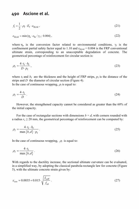
Debonding -- Two different collapse modes for debonding are considered: end
debonding (mode I) and intermediate debonding for flexural cracking (mode II).
The optimal anchorage length of FRP strip (Figure 1) is given as (length units in
mm):
f f
e
ctm2
E t
l
f
⋅
=
⋅
, (3)

FRPRCS-7 487where E
f is the modulus of the FRP overlay in the fibers direction, t
f is the thickness of
FRP and fctm
is the concrete mean tensile strength.
The design debonding strength for end debonding (Mode I) is:
f Fk
fdd
ff,d c
21 E
f
t
⋅ ⋅
= ⋅
⋅
Γ
γ γ
, (4)
with Fk b ck ctm
0 03. k f f= ⋅ ⋅ ⋅Γ (forces in N, lengths in mm) , (5)
where ΓFk
is the characteristic value of fracture energy of bond between concrete and
FRP, kb is a scale/covering coefficient ≥1, γ
f,d is the delamination partial factor, and f
ck is
the concrete characteristic strength.
The design debonding strain for intermediate debonding is:
cr fdd
fdd
f
k f
E
⋅
=ε , (6)
where kcr
is a coefficient assumed equal to 3.0.
Flexure -- The flexural capacity is attained when either the concrete compressive
strain reaches its ultimate value or when the FRP tensile strain reaches its ultimate value
εfd
= min(ηaε
fu/γ
f, f
fdd/E
f) where the first value corresponds to failure and the second to
the design debonding as previously defined. The flexural capacity is then given as
(notation in Figure 2):
Rd cd s2 s2 2 f f 1
Rd
1
( ) ( )M b x f d x A d d A d= ⋅ ⋅ ⋅ ⋅ ⋅ − ⋅ + ⋅ ⋅ − + ⋅ ⋅ ψ λ σ σ
γ
, (7)
where the neutral axis x is found by solving:
cd s2 s2 s1 yd f f0 b x f A A f A= ⋅ ⋅ ⋅ + ⋅ − ⋅ − ⋅ψ σ σ , (8)
in which σs2
is the stress in the superior compressed re-bars, σf is the tensile stress in the
FRP reinforcement, fcd
is the concrete design strength, fyd
is the yield stress in the inferior
re-bars, ψ and λ are non-dimensional coefficients representing the intensity and the
position of the compressive concrete resultant, respectively. However, the strengthened
capacity cannot be considered as greater than the 60% of initial capacity.
Flexure in the presence of axial force – The flexural capacity in the presence of an
axial force Nsd
can be evaluated by means of eqns. (7 and 8), substituting the first
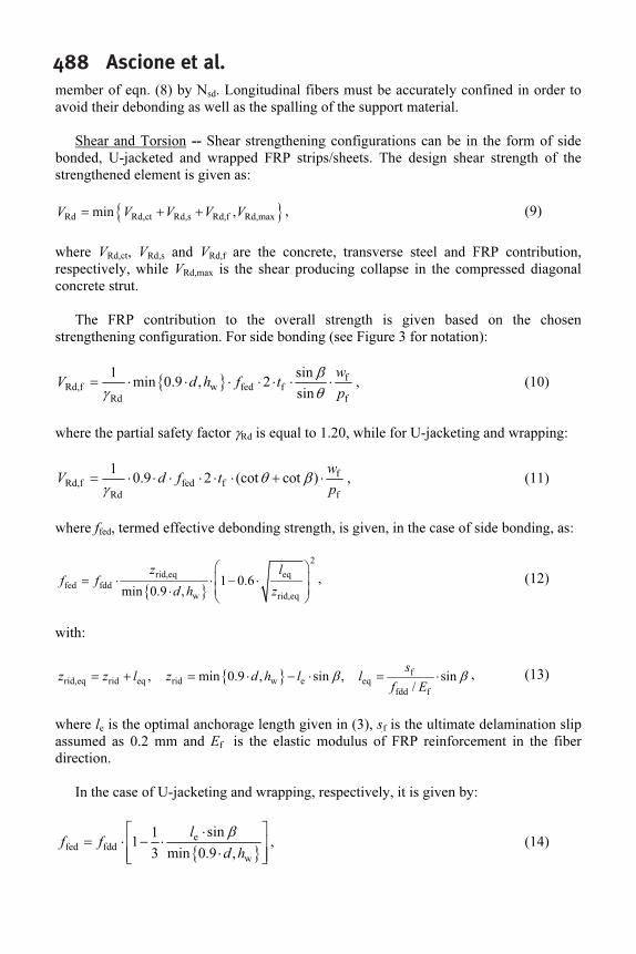
488 Ascione et al.member of eqn. (8) by N
sd. Longitudinal fibers must be accurately confined in order to
avoid their debonding as well as the spalling of the support material.
Shear and Torsion -- Shear strengthening configurations can be in the form of side
bonded, U-jacketed and wrapped FRP strips/sheets. The design shear strength of the
strengthened element is given as:
{ }Rd Rd,ct Rd,s Rd,f Rd,maxmin ,V V V V V= + + , (9)
where VRd,ct
, VRd,s
and VRd,f
are the concrete, transverse steel and FRP contribution,
respectively, while VRd,max
is the shear producing collapse in the compressed diagonal
concrete strut.
The FRP contribution to the overall strength is given based on the chosen
strengthening configuration. For side bonding (see Figure 3 for notation):
{ }f
Rd,f w fed f
Rd f
1 sin
min 0.9 , 2
sin
w
V d h f t
p
= ⋅ ⋅ ⋅ ⋅ ⋅ ⋅ ⋅
β
γ θ
, (10)
where the partial safety factor γRd
is equal to 1.20, while for U-jacketing and wrapping:
f
Rd,f fed f
Rd f
1
0.9 2 (cot cot )
w
V d f t
p
= ⋅ ⋅ ⋅ ⋅ ⋅ ⋅ + ⋅θ β
γ
, (11)
where ffed
, termed effective debonding strength, is given, in the case of side bonding, as:
{ }
2
rid,eq eq
fed fdd
w rid,eq
1 0.6
min 0.9 ,
z l
f f
d h z
= ⋅ ⋅ − ⋅
⋅
, (12)
with:
{ }f
rid,eq rid eq rid w e eq
fdd f
, min 0.9 , sin , sin
/
s
z z l z d h l l
f E
= + = ⋅ − ⋅ = ⋅β β , (13)
where le is the optimal anchorage length given in (3), s
f� is the ultimate delamination slip
assumed as 0.2 mm and Ef
is the elastic modulus of FRP reinforcement in the fiber
direction.
In the case of U-jacketing and wrapping, respectively, it is given by:
{ }
e
fed fdd
w
sin1
1
3 min 0.9 ,
l
f f
d h
⋅
= ⋅ − ⋅
⋅
β
, (14)
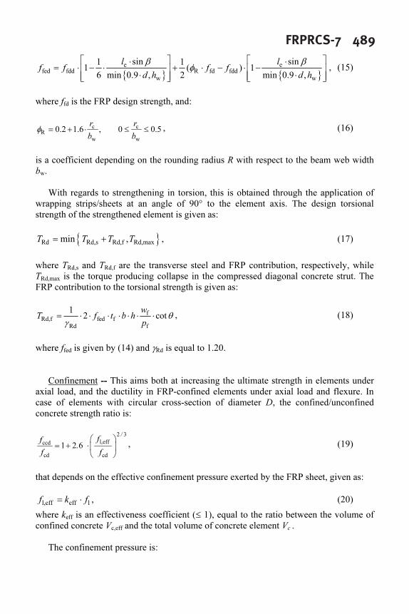
FRPRCS-7 489
{ } { }
e e
fed fdd R fd fdd
w w
sin sin1 1
1 ( ) 1
6 min 0.9 , 2 min 0.9 ,
l l
f f f f
d h d h
⋅ ⋅
= ⋅ − ⋅ + ⋅ − ⋅ −
⋅ ⋅
β β
φ , (15)
where ffd
is the FRP design strength, and:
c c
R
w w
0.2 1.6 , 0 0.5
r r
b b
= + ⋅ ≤ ≤φ , (16)
is a coefficient depending on the rounding radius R with respect to the beam web width
bw.
With regards to strengthening in torsion, this is obtained through the application of
wrapping strips/sheets at an angle of 90° to the element axis. The design torsional
strength of the strengthened element is given as:
{ }Rd Rd,s Rd,f Rd,maxmin ,T T T T= + , (17)
where TRd,s
and TRd,f
are the transverse steel and FRP contribution, respectively, while
TRd,max
is the torque producing collapse in the compressed diagonal concrete strut. The
FRP contribution to the torsional strength is given as:
f
Rd,f fed f
Rd f
1
2 cot
w
T f t b h
p
= ⋅ ⋅ ⋅ ⋅ ⋅ ⋅ ⋅ θ
γ
, (18)
where ffed
is given by (14) and γRd
is equal to 1.20.
Confinement -- This aims both at increasing the ultimate strength in elements under
axial load, and the ductility in FRP-confined elements under axial load and flexure. In
case of elements with circular cross-section of diameter D, the confined/unconfined
concrete strength ratio is:
2 3
l,effccd
cd cd
1 2 6
/
ff
.
f f
= + ⋅
, (19)
that depends on the effective confinement pressure exerted by the FRP sheet, given as:
l,eff eff lf k f= ⋅ , (20)
where keff
is an effectiveness coefficient (≤ 1), equal to the ratio between the volume of
confined concrete Vc,eff
and the total volume of concrete element Vc .
The confinement pressure is:
490 Ascione et al.
l f f fd,rid
1
2
f E= ⋅ ⋅ ⋅ρ ε , (21)
fd,rid a fk fmin{ / ; 0.004}= ⋅ε η ε γ , (22)
where ηa is the conversion factor related to environmental conditions, γ
f is the
confinement partial safety factor equal to 1.10 and εfd,rid
= 0.004 is the FRP conventional
ultimate strain, corresponding to an unacceptable degradation of concrete. The
geometrical percentage of reinforcement for circular section is:
f f
f
f
4 t b
D p
⋅ ⋅
=
⋅
ρ , (23)
where tf and b
f are the thickness and the height of FRP strips, p
f is the distance of the
strips and D the diameter of circular section (Figure 4).
In the case of continuous wrapping, ρf is equal to:
f
f
4 t
D
⋅
=ρ . (24)
However, the strengthened capacity cannot be considered as greater than the 60% of
the initial capacity.
For the case of rectangular sections with dimensions b × d, with corners rounded with
a radius rc ≥ 20 mm, the geometrical percentage of reinforcement can be computed by:
{ }
f f
f
f
4
max ,
t b
b d p
⋅ ⋅
=
⋅
ρ . (25)
In the case of continuous wrapping, ρf is equal to:
{ }
f
f
4
max ,
t
b d
⋅
=ρ . (26)
With regards to the ductility increase, the sectional ultimate curvature can be evaluated,
in a simplified way, by adopting the classical parabola-rectangle law for concrete (Figure
5), with the ultimate concrete strain given by:
l,eff
ccu
cd
0.0035 0.015
f
f
= + ⋅ε . (27)
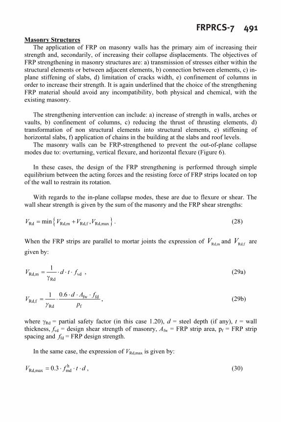
FRPRCS-7 491Masonry Structures
The application of FRP on masonry walls has the primary aim of increasing their
strength and, secondarily, of increasing their collapse displacements. The objectives of
FRP strengthening in masonry structures are: a) transmission of stresses either within the
structural elements or between adjacent elements, b) connection between elements, c) in-
plane stiffening of slabs, d) limitation of cracks width, e) confinement of columns in
order to increase their strength. It is again underlined that the choice of the strengthening
FRP material should avoid any incompatibility, both physical and chemical, with the
existing masonry.
The strengthening intervention can include: a) increase of strength in walls, arches or
vaults, b) confinement of columns, c) reducing the thrust of thrusting elements, d)
transformation of non structural elements into structural elements, e) stiffening of
horizontal slabs, f) application of chains in the building at the slabs and roof levels.
The masonry walls can be FRP-strengthened to prevent the out-of-plane collapse
modes due to: overturning, vertical flexure, and horizontal flexure (Figure 6).
In these cases, the design of the FRP strengthening is performed through simple
equilibrium between the acting forces and the resisting force of FRP strips located on top
of the wall to restrain its rotation.
With regards to the in-plane collapse modes, these are due to flexure or shear. The
wall shear strength is given by the sum of the masonry and the FRP shear strengths:
{ }Rd Rd,m Rd,f Rd,maxmin ,V V V V= + . (28)
When the FRP strips are parallel to mortar joints the expression of Rd,m
V and Rd,f
V are
given by:
Rd,m vd
Rd
1
V d t f= ⋅ ⋅ ⋅
γ
, (29a)
fw fd
Rd,f
Rd f
0.61 d A f
V
p
⋅ ⋅ ⋅
= ⋅
γ
, (29b)
where γRd
= partial safety factor (in this case 1.20), d = steel depth (if any), t = wall
thickness, fvd
= design shear strength of masonry, Afw
= FRP strip area, pf = FRP strip
spacing and ffd
= FRP design strength.
In the same case, the expression of VRd,max
is given by:
h
Rd,max md0.3V f t d= ⋅ ⋅ ⋅ , (30)

492 Ascione et al.where
h
mdf is the masonry compressive resistance in the horizontal direction, it is
parallel to the mortar joints.
When strengthening elements with either single (barrel vaults, in Figure 7) or double
(groin and cross vaults, in Figure 8) curvature, the FRP strips should contrast the relative
rotation at the hinge zones that develop where the limited tensile strength of masonry is
attained. Thus, application of FRP strips over the outer (inner) surface of the vault
thickness can prevent the formation of hinges on the opposite inner (outer) surface.
The FRP strengthening of arches includes two possible structural schemes: a) arch on
fixed restraints, and b) arch supported by columns. The aim is to avoid the formation of
four hinges, which would imply collapse. The FRP-strengthening is applied on either
(preferably) the outer or the inner surface, in the form of fabrics that adapt better to a
curved shape than prefab strips.
The FRP strengthening of domes should increase the capacity of both the membrane
and the flexural regimes. For the former, FRP strips should be applied circumferentially
around the dome base (Figure 9) , while for the latter, FRP strips should be applied along
the meridians.
The load bearing capacity of masonry columns can be increased by confining them
through FRP. The confining system can consists in an external overlay and/or in internal
bars. The confined strength (which cannot be taken as greater than 1.5 the initial
strength) can be computed as:
mcd md l,eff'f f k f= + ⋅ , (31)
where fmd
is the initial masonry strength and k’ is an effectiveness coefficient that can be
assumed equal to:
m
'
1000
g
k = , (32)
where gm
(kg/m3
) is the mass density of masonry, when there isn’t specific experimental
evaluations.
The effective confining pressure fl,eff
is evaluated as:
l,eff eff l H V lf k f k k f= ⋅ = ⋅ ⋅ , (33)
with l f f b b fd,rid
1
( 2 )
2
f E E= ⋅ ⋅ + ⋅ ⋅ ⋅ρ ρ ε , (34)

FRPRCS-7 493where E
f is the modulus of the FRP external overlay in the fibers direction, E
b is the
longitudinal elastic modulus of the FRP internal bars, εf,rid
= 0.004, ρf and ρ
b are the
FRP external overlay and the FRP internal bars ratios, respectively.
FRP Strengthening in Seismic Zones
The above described chapters on strengthening also contain specific indications
regarding constructions in seismic zones. These follow the approach of the most recent
Italian and International codes, with regards to: assessment techniques, safety
requirements (limit states), seismic protection levels, analysis methods, and verification
criteria (distinction between ductile and brittle elements).
Reinforced Concrete Buildings -- FRP strengthening is regarded as a selective
intervention technique aiming at: a) increasing the flexural and shear capacity of
deficient members, b) increasing the ductility (or the chord rotation capacity) of critical
zones through confinement, c) improving the performance of lap splice zones through
confinement, d) prevent longitudinal steel bars buckling through confinement, and e)
increase the tensile strength in partially confined beam-column joints through application
of diagonal strips.
A relevant innovation concerns the definition of the inspiring principles of the
intervention strategies: a) all brittle collapse mechanism should be eliminated, b) all
“soft story” collapse mechanism should be eliminated, and c) the global deformation
capacity of the structure should be enhanced, either: c1) by increasing the ductility of the
potential plastic hinge zones without changing their position, or c2) by relocating the
potential plastic hinge zones by applying capacity design criteria. In this latter case, the
columns should be flexure-strengthened with the aim of transforming the frame structure
into a high dissipation mechanism with strong columns and weak beams.
Failure of brittle mechanisms such as shear, lap splicing, bar buckling, and joint shear
should be avoided. For shear, the same criteria apply as for the non-seismic case, with
the exception that side bonding is not allowed and FRP strips/sheets should only be
applied orthogonal to the element axis. For lap splices of length Ls, adequate FRP
confinement should be provided, having thickness:
{ }
f S
f
max ,
1000
2
l
H
b d f
t E
E k
= ⋅ ⋅ − ⋅
, (35)
where Es = steel modulus, and f
l = confinement pressure:
s y
l
e
b s2 ( )
2
A f
f
u
d c L
n
⋅
=
+ ⋅ + ⋅
⋅
, (36)

494 Ascione et al.where u
e= perimeter of the cross section inscribed in the longitudinal bars, of which n
are spliced, and c = concrete cover. For bar buckling, adequate FRP confinement should
be provided, having thickness:
{ }
f
f
10 max ,n b d
t
E
⋅ ⋅
= , (37)
where n = total number of longitudinal bars under potential buckling.
Masonry Buildings -- Starting from the same principles as for RC buildings, when
FRP-strengthening a masonry building one should also consider that: a) masonry walls
inadequate to resist vertical and horizontal actions should be strengthened or rebuilt, b)
orthogonal and corner walls should be adequately connected, c) slab/wall and roof/wall
connections should be ensured, d) thrusts from roofs, arches and vaults should be
counter-reacted by appropriate structural elements, e) slabs should be in-plane stiffened,
f) vulnerable elements that cannot be strengthened should be eliminated, g) irregularity
of buildings cannot be corrected by FRP applications, h) local ductility increase should
be pursued whenever possible, and i) the application of local FRP strengthening should
not reduce the overall structural ductility.
Quality Control
A series of in situ checks and operations are specified in order to validate the quality
level of the applications of composite materials: check and preparation of the substrate,
evaluation of the substrate degradation, removal and reconstruction of the substrate with
possible treatment of steel bars.
A series of requirements for a correct application are also given with regards to:
humidity conditions, environmental and substrate temperature, construction details and
rules. The quality control of the application is then based on semi-destructive and non-
destructive tests.
CONCLUSIONS
The peculiarity of Italy, highly seismic and endowed with a built environment unique
in the world, extremely various and rich of cultural value, renders all research in this
field a continuous and challenging task.
This nationwide effort has resulted in a first regulatory document (CNR-DT
200/2004), that was conceived both for regulating a rapidly growing professional and
technical market, as well as for an informative and educational purpose. The document is
deemed of great importance for the dissemination, in the professional sphere, of the
physical and technological knowledge necessary to conscious and competent use of FRP
in strengthening.
A version in English of the document is under preparation and will be available in
summer 2005.
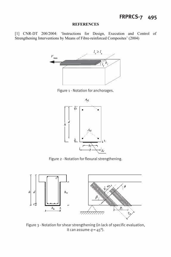
FRPRCS-7 495REFERENCES
[1] CNR-DT 200/2004: ‘Instructions for Design, Execution and Control of
Strengthening Interventions by Means of Fibre-reinforced Composites’ (2004)
Figure 1 - Notation for anchorages.
Figure 2 - Notation for flexural strengthening.
Figure 3 - Notation for shear strengthening (in lack of specific evaluation,it can assume q = 45°).

496 Ascione et al.
Figure 4 - Notation for confinement (column vertical section).
Figure 5 – Parabola-rectangle law (fcd
= concrete design strength).
Figure 6 - Collapse modes of masonry walls: overturning (left) andhorizontal flexure (right).

FRPRCS-7 497
Figure 7 - FRP strengthening of a masonry barrel vault.
Figure 8 - FRP strengthening of a masonry cross vault.
Figure 9 - FRP strengthening of a masonry dome.

498 Ascione et al.