design, implementation, and evaluation of parallell
TRANSCRIPT

Syracuse University Syracuse University
SURFACE SURFACE
Electrical Engineering and Computer Science College of Engineering and Computer Science
1998
Design, implementation, and evaluation of parallell pipelined STAP Design, implementation, and evaluation of parallell pipelined STAP
on parallel computers on parallel computers
Alok Choudhary Northwestern University
Wei-keng Liao Northwestern University
Donald Weiner Syracuse University
Pramod Varshney Syracuse University
Richard Linderman Air Force Research Laboratory
See next page for additional authors
Follow this and additional works at: https://surface.syr.edu/eecs
Part of the Computer Sciences Commons
Recommended Citation Recommended Citation Choudhary, Alok; Liao, Wei-keng; Weiner, Donald; Varshney, Pramod; Linderman, Richard; and Linderman, Mark, "Design, implementation, and evaluation of parallell pipelined STAP on parallel computers" (1998). Electrical Engineering and Computer Science. 49. https://surface.syr.edu/eecs/49
This Article is brought to you for free and open access by the College of Engineering and Computer Science at SURFACE. It has been accepted for inclusion in Electrical Engineering and Computer Science by an authorized administrator of SURFACE. For more information, please contact [email protected].

Author(s)/Creator(s) Author(s)/Creator(s) Alok Choudhary, Wei-keng Liao, Donald Weiner, Pramod Varshney, Richard Linderman, and Mark Linderman
This article is available at SURFACE: https://surface.syr.edu/eecs/49

Design, Implementation andEvaluation of Parallel PipelinedSTAP on Parallel Computers
ALOK CHOUDHARY
WEI-KENG LIAONorthwestern University
DONALD WEINER, Life Fellow, IEEE
PRAMOD VARSHNEY, Fellow, IEEESyracuse University
RICHARD LINDERMAN, Senior Member, IEEE
MARK LINDERMAN, Member, IEEE
RUSSELL BROWN, Fellow, IEEEAir Force Research Laboratory
Performance results are presented for the design andimplementation of parallel pipelined space-time adaptiveprocessing (STAP) algorithms on parallel computers. Inparticular, the issues involved in parallelization, our approachto parallelization, and performance results on an Intel Paragonare described. The process of developing software for such anapplication on parallel computers when latency and throughputare both considered together is discussed and tradeoffs consideredwith respect to inter and intratask communication and dataredistribution are presented. The results show that not onlyscalable performance was achieved for individual component tasksof STAP but linear speedups were obtained for the integrated taskperformance, both for latency as well as throughput. Results arepresented for up to 236 compute nodes (limited by the machinesize available to us). Another interesting observation made fromthe implementation results is that performance improvementdue to the assignment of additional processors to one task canimprove the performance of other tasks without any increase inthe number of processors assigned to them. Normally, this cannotbe predicted by theoretical analysis.
Manuscript received January 29, 1999; revised June 9 andDecember 6, 1999; released for publication December 11, 1999.
IEEE Log No. T-AES/36/2/05228.
Refereeing of this contribution was handled by W. D. Blair.
This work was supported by Air Force Material Command underContract F30602-97-C-0026.
Authors’ addresses: A. Choudhary and W. Liao, Electrical andComputer Engineering Dept., Northwestern University, Evanston,IL 60208; D. Weiner and P. Varshney, Electrical Engineeringand Computer Science Dept., Syracuse University, 121 LinkHall, Syracuse, NY 13244; R. Linderman and M. Linderman,AFRL/IFTC, 26 Electronics Parkway, Air Force ResearchLaboratory, Rome, NY 13441; R. Brown, AFRL/SNRT, 26Electronics Parkway, Air Force Research Laboratory, Rome, NY13441.
0018-9251/00/$10.00 c° 2000 IEEE
I. INTRODUCTION
Space-time adaptive processing (STAP) isa well-known technique in the area of airbornesurveillance radars used to detect weak target returnsembedded in strong ground clutter, interference, andreceiver noise. STAP is a 2-dimensional adaptivefiltering algorithm that attenuates unwanted signalsby placing nulls in their directions of arrival andDoppler frequencies. Most STAP applications arecomputationally intensive and must operate in realtime. High-performance computers are becomingmainstream due to the progress made in hardware aswell as software support in the last few years. Theycan satisfy the STAP computational requirements ofreal-time applications while increasing the flexibility,affordability, and scalability of radar signal processingsystems. However, efficient parallelization of aSTAP algorithm which has embedded in it differentprocessing steps is challenging and is the subject ofthis paper.Described here is our innovative parallel pipelined
implementation of a pulse repetition interval(PRI)-staggered post-Doppler STAP algorithm on theIntel Paragon at the Air Force Research Laboratory(AFRL), Rome, NY. For a detailed description ofthe STAP algorithm implemented in this work,the reader is referred to [1, 2]. AFRL successfullyinstalled their implementation of the STAP algorithmonboard an airborne platform and performed fourflight experiments in May and June 1996 [3]. Theseexperiments were performed as part of the Real-TimeMulti-Channel Airborne Radar Measurements(RTMCARM) program. The RTMCARM systemblock diagram is shown in Fig. 1. In that real-timedemonstration, live data from a phased-array radarwas processed by the onboard Intel Paragon andresults showed that high-performance computers candeliver a significant performance gain. However, thisimplementation used compute nodes of the machineonly as independent resources in a round robinfashion to run different instances of STAP (ratherthan speeding up each instance of STAP.) Using thisapproach, the throughput may be improved, but thelatency is limited by what can be achieved using onecompute node.Parallel computers, organized with a large
set (several hundreds) of processors linked by aspecialized high speed interconnection network,offer an attractive solution to many computationallyintensive applications, such as image processing,simulation of particle reactions, and so forth.Parallel processing splits an application problem intoseveral subproblems which are solved on multipleprocessors simultaneously. To learn more aboutparallel computing, the reader is referred to [4—8]. Forour parallel implementation of this real application wehave designed a model of the parallel pipeline system
528 IEEE TRANSACTIONS ON AEROSPACE AND ELECTRONIC SYSTEMS VOL. 36, NO. 2 APRIL 2000

Fig. 1. RTMCARM system block diagram.
where each pipeline is a collection of tasks and eachtask itself is parallelized. This parallel pipeline modelwas applied to the STAP algorithm with each step asa task in a pipeline. This permits us to significantlyimprove latency as well as throughput.This paper discusses both the parallelization
process and performance results. In addition,design considerations for portability, task mapping,parallel data redistribution, parallel pipelining aswell as system-level and task-level performancemeasurement are presented. Finally, the performanceand scalability of the implementation for a largenumber of processors is demonstrated. Performanceresults are given for the Intel Paragon at AFRL.The paper is organized as follows. In Section II
we discuss the related work. An overview of theimplemented algorithm is given in Section III.In Section IV we present the parallel pipelinesystem model and discuss some parallelizationissues and approaches for implementation of STAPalgorithms. Section V presents specific details ofSTAP implementation. Software development ispresented in Section VI. Performance results andconclusions are presented in Sections VII and VIII,respectively.
II. RELATED WORK
The RTMCARM experiments were performedusing a BAC 1-11 aircraft. The radar was aphased-array L-Band radar with 32 elementsorganized into two rows of 16 each. Only the data
from the upper 16 elements were processed withSTAP. This data was derived from a 1.25 MHzIF signal that was 4 : 1 oversampled at 5 MHz.The number representation at IF was 14 bits, 2scomplement and was converted to 16 bit baseband realand imaginary numbers. Special interface boards wereused to digitally demodulate IF signals to baseband.The signal data formed a raw 3-dimensional datacube, called the coherent processing interval (CPI)data cube, comprised of 128 pulses, 512 range gates(32.8 mi), and 16 channels. These special interfaceboards were also used to corner turn the data cube sothat the CPI is unit stride along pulses. This speedsthe subsequent Doppler processing on the highperformance computing (HPC) systems. Live CPIdata from a phased-array radar were processed by aruggedized version of the Paragon computer.The ruggedized version of the Intel Paragon
system used for the RTMCARM experimentsconsists of 25 compute nodes running the SUNMOSoperating system. Fig. 2 depicts the systemimplementation. Each compute node has threei860 processors accessing the common memoryof size 64M bytes as a shared resource. The CPIdata sets were sent to the 25 compute nodes ina round robin manner and all three processorsworked on each CPI data set as a shared-memorymachine. The system processed up to 10 CPIs/s(throughput) and achieved a latency of 2.35 s/CPI.This implementation used compute nodes of themachine as independent resources to run differentinstances of CPI data sets. No communication
CHOUDHARY ET AL: DESIGN, IMPLEMENTATION AND EVALUATION OF PARALLEL PIPELINED STAP 529

Fig. 2. Implementation of ruggedized version of Intel Paragon System in RTMCARM experiments.
among compute nodes was needed. This approachcan achieve desired throughput by using as manynodes as needed, but the latency is limited by whatcan be achieved using the three processors in onecompute node. More information on the overallsystem configuration and performance results can befound in [1, 3].Other related work [9—12] parallelized high-order
post-Doppler STAP algorithms by partitioningthe computational workload among all processorsallocated for the applications. In [9, 10], the workfocused on the design of parallel versions ofsubroutines for fast Fourier transform (FFT) andQR decomposition. In [11, 12], the implementationsoptimized the data redistribution between processingsteps in the STAP algorithms while using sequentialversions of the FFT and QR decompositionsubroutines. A multistage approach was employedin [13] which was an extension of [11, 12]. A beamspace post-Doppler STAP was divided into threestages and each stage was parallelized on a groupof processors. A technique called replication ofpipeline stages was used to replicate the computationalintensive stages such that a different data instanceis run on a different replicated stage. Their effortfocused on increasing the throughput while keepingthe latency fixed. For other related work, the reader isreferred to [14—16].
III. ALGORITHM OVERVIEW
The adaptive algorithm, which cancelsDoppler-shifted clutter returns as seen by the airborneradar system, is based on a least squares solutionto the weight vector problem. This approach hastraditionally yielded high clutter rejection but suffersfrom severe distortions in the adapted mainbeampattern and resulting loss of gain on the target. Ourapproach, which is described in greater detail in theAppendix, introduces a set of constraint equationsinto the least squares problem which can be weighted
proportionally to preserve mainbeam shape. Thealgorithm is structured so that multiple receivebeams may be formed without changing the matrixof training data. Thus, the adaptive problem canbe solved once for all beams which lie within thetransmit illumination region. The airborne radarsystem was programmed to transmit five beams, each25 deg in width, spaced 20 deg apart. Within eachtransmit beam, six receive beams were formed by theprocessor.A MATLAB version of the code which was
parallelized is presented in the Appendix. Thealgorithm consists of the following steps.
1) Doppler filter processing.2) Weight computation.3) Beamforming.4) Pulse compression.5) CFAR processing.
Doppler filtering is performed on each receivechannel using weighted FFTs. The analog portionof the receiver compensates the received clutterfrequency to center the clutter frequency at zeroregardless of the transmit beam position. Thissimplifies indexing of Doppler bins for classificationas “easy” or “hard” depending on their proximityto mainbeam clutter returns. For the hard cases,Doppler processing is performed on two 125-pulsewindows of data separated by three pulses (a STAPtechnique known as “PRI-stagger”). Both sets ofDoppler processed data are adaptively weightedin the beamforming process for improved clutterrejection. In the easy case, only a single Dopplerspectrum is computed. This simpler technique hasbeen termed post-Doppler adaptive beamforming andis quite effective at a fraction of the computationalcost when the Doppler bin is well separated frommainbeam clutter. In these situations, an angularnull placed in the direction of the competing groundclutter provides excellent rejection. Selectablewindow functions are applied to the data prior to
530 IEEE TRANSACTIONS ON AEROSPACE AND ELECTRONIC SYSTEMS VOL. 36, NO. 2 APRIL 2000

the Doppler FFTs to control sidelobe levels. Theselection of a window is a key parameter in that itimpacts the leakage of clutter returns across Dopplerbins, traded off against the width of the clutterpassband.An efficient method of beamforming using
recursive weight updates is made possible by a blockupdate form of the QR decomposition algorithm.This is especially significant in the hard Dopplerregions, which are computed using separate weightsfor six consecutive range intervals. The recursivealgorithm requires substantially less training data(sample support) for accurate weight computation,as well as providing improved efficiency. Sincethe hard regions have one-sixth the range extentfrom which to draw data, this approach dealt withthe paucity of data by using past looks at the sameazimuth, exponentially forgotten, as independent,identically distributed estimates of the clutter tobe canceled. This assumes a reasonable revisittime for each azimuth beam position. Duringthe flight experiments, the five 25 deg transmitbeam positions were revisited at a 1—2 Hz rate(5—10 CPIs/s).The training data for the easy Doppler regions
was selected using a more traditional approach. Here,the entire range extent was available for samplesupport, so the entire training set was drawn fromthree preceding CPIs for application to the next CPIin this azimuth beam position. In this case, a regular(nonrecursive) QR decomposition is performed on thetraining data, followed by block update to add in thebeam shape constraints.Pulse compression is a compute intensive
task, especially if applied to each receive channelindependently. In general, this approach is required foradaptive algorithms which compute different weightsets as a function of radar range. Our algorithm,however, with its mainbeam constraint, preservesphase across range. In fact, the phase of the solutionis independent of the clutter nulling equations,and appears only in the constraint equations. Theadapted target phase is preserved across range,even though the clutter and adaptive weights mayvary with range. Thus, pulse compression maybe performed on the beamformed output of thereceive channels providing a substantial savings incomputations.In the sections to follow, we present the process
of parallelization and software design considerationsincluding those for portability, task mapping,parallel data redistribution, parallel pipeliningand issues involved in measuring performance inimplementations when not only the performance ofindividual tasks is important, but overall performanceof the integrated system is critical. We demonstratethe performance and scalability for a large number ofprocessors.
Fig. 3. Model of parallel pipeline system. (Note that Taski for allinput instances is excuted on same number of processors, but thatthe number of processors may differ from one task to another.)
IV. MODEL OF PARALLEL PIPELINED SYSTEM
The system model for the type of STAPapplications considered in this work is shown inFig. 3. A pipeline is a collection of tasks which areexecuted sequentially. The input to the first taskis obtained normally from sensors or other inputdevices with the inputs to the remaining tasks comingfrom outputs of previous tasks. The set of pipelinesshown in the figure indicates that the same pipelineis repeated on subsequent input data sets. Each blockin a pipeline represents one task that is parallelizedon multiple (different number of) processors. Thatis, each task is decomposed into subtasks to beperformed in parallel. Therefore, each pipeline is acollection of parallel tasks.In such a system, there exist both spatial and
temporal parallelism that result in two types ofdata dependencies and flows, namely, spatialdata dependency and temporal data dependency[17—19]. Spatial data dependency can be classifiedinto intertask data dependency and intratask datadependency. Intratask data dependencies arise when aset of subtasks needs to exchange intermediate resultsduring the execution of a parallel task in a pipeline.Intertask data dependency is due to the transfer andreorganization of data passed onto the next paralleltask in the pipeline. Inter-task communication canbe communication from the subtasks of the currenttask to the subtasks of the next task, or collectionand reorganization of output data of the current taskand then redistribution of the data to the next task.The choice depends on the underlying architecture,mapping of algorithms and input-output relationshipbetween consecutive tasks. Temporal data dependencyoccurs when some form of output generated by thetasks executed on the previous data set are neededby tasks executing the current data set. STAP is an
CHOUDHARY ET AL: DESIGN, IMPLEMENTATION AND EVALUATION OF PARALLEL PIPELINED STAP 531

interesting parallelization problem because it exhibitsboth types of data dependency.
A. Parallelization Issues and Approaches
A STAP algorithm involves multiple algorithms(or processing steps), each of which performsparticular functions, to be executed in a pipelinedfashion. Multiple pipelines need to be executedin a staggered manner to satisfy the throughputrequirements. Each task needs to be parallelized forthe required performance, which, in turn, requiresaddressing the issue of data distribution on the subsetof processors on which a task is parallelized to obtaingood efficiency and incur minimal communicationoverhead. Given that each task is parallelized, dataflow among multiple processors of two or more tasksis required and, therefore, communication schedulingtechniques become critical.1) Intertask Data Redistribution: In an integrated
system, data redistribution is required to feed datafrom one parallel task to another, because theway data is distributed in one task may not be themost appropriate distribution for the next task foralgorithmic or efficiency reasons. For example, theFFTs in the Doppler filter processing task performoptimally when the data is unit-stride in pulse, whilethe next stage, beamforming, performs optimallywhen the data is unit stride in channel. To ensureefficiency and continuity of memory access, datareorganization and redistribution are required in theinter-task communication phase. Data redistributionalso allows concentration of communication at thebeginning and the end of each task.We have developed runtime functions and
strategies that perform efficient data redistribution[20]. These techniques reduce the communicationtime by minimizing contention on the communicationlinks as well as by minimizing the overhead ofprocessing for redistribution (which adds to thelatency of sending messages). We take advantage oflessons learned from these techniques to implementthe parallel pipelined STAP application.2) Task Scheduling and Processor Assignment:
An important factor in the performance of a parallelsystem is how the computational load is mappedonto the processors in the system. Ideally, to achievemaximum parallelism, the load must be evenlydistributed across the processors. The problemof statically mapping the workload of a parallelalgorithm to processors in a distributed memorysystem has been studied under different problemmodels, such as [21, 22]. The mapping policies areadequate when an application consists of a singletask, and the computational load can be determinedstatically. These static mapping policies do notmodel applications consisting of a sequence of tasks
(algorithms) where the output of one task becomes theinput to the next task in the sequence.Optimal use of resources is particularly important
in high-performance embedded applications dueto limited resources and other constraints such asdesired latency or throughput [23]. When severalparallel tasks need to be executed in a pipelinedfashion, tradeoffs exist between assigning processorsto maximize the overall throughput and assigningprocessors to minimize the response time (or latency)of a single data set. The throughput requirement saysthat when allocating processors to tasks, it should beguaranteed that all the input data sets will be handledin a timely manner. That is, the processing rate shouldnot fall behind the input data rate. The response timecriteria, on the other hand, require minimizing thelatency of computation on a particular set of datainput.To reduce the latency, each parallel task must be
allocated more processors to reduce its executiontime, and consequently, the overall execution time ofthe integrated system. But it is well known that theefficiency of parallel programs usually decreases asthe number of processors is increased. Therefore, thegains in this approach may be incremental. On theother hand, throughput can be increased by increasingthe latency of individual tasks by assigning themfewer processors and, therefore, increasing efficiency,but at the same time having multiple streams activeconcurrently in a staggered manner to satisfy theinput-data rate requirements. We next present thesetradeoffs and discuss various implementation issues.
V. DESIGN AND IMPLEMENTATION
The design of the parallel pipelined STAPalgorithm is shown in Fig. 4. The parallel pipelinesystem consists of seven basic tasks. We refer to theparallel pipeline as simply a pipeline in the rest of thispaper. The input data set for the pipeline is obtainedfrom a phased-array radar and is formed in terms ofa CPI. Each CPI data set is a 3-dimensional complexdata cube comprised of K range cells, J channels, andN pulses. The output of the pipeline is a report onthe detection of possible targets. The arrows shown inFig. 4 indicate data transfer between tasks. Althougha single arrow is shown, note that each representsmultiple processors in one task communicating withmultiple processors in another task. Each task i isparallelized by evenly partitioning its work loadamong Pi processors. The execution time associatedwith task i, Ti, consists of the time to receive datafrom the previous task, computation time, and timeto send results to the next task.The calculation of weights is the most
computationally intensive part of the STAP algorithm.For the computation of the weight vectors for thecurrent CPI data cube, data cubes from previous
532 IEEE TRANSACTIONS ON AEROSPACE AND ELECTRONIC SYSTEMS VOL. 36, NO. 2 APRIL 2000

Fig. 4. Implementation of parallel pipelined STAP. Arrows connecting task blocks represent data transfer between tasks.
CPIs are used as input data. This introduces temporaldata dependency. For example, suppose that a set ofCPI data cubes entering the pipeline sequentially aredenoted by CPIi, i= 0,1, : : : . At any time instancei, the Doppler filtering task is processing CPIi andthe beamforming task is processing CPIi¡1. In themeanwhile, the weight computation task is usingpast CPIs in the same azimuthal direction to calculatethe weight vectors for CPIi as described below. Thecomputed weight vectors will be applied to CPIiin the beamforming task at the next time instance(i+1). Thus, temporal data dependencies exist and arerepresented by arrows with dashed lines, TD1,3 andTD2,4, in Fig. 4 where TDi,j represents temporal datadependency of task j on data from task i. In a similarmanner, spatial data dependencies SDi,j can be definedand are indicated in Fig. 4 by arrows with solid lines.Throughput and latency are two important
measures for performance evaluation on a pipelinesystem. The throughput of our pipeline system is theinverse of the maximum execution time among alltasks, i.e.,
throughput =1
max0·i<7Ti: (1)
To maximize the throughput, the maximum value of Tishould be minimized. In other words, no task shouldhave an extremely large execution time. With a limitednumber of processors, the processor assignment todifferent tasks must be made in such a way that theexecution time of the task with highest computationtime is reduced.The latency of this pipeline system is the time
between the arrival of the CPI data cube at the systeminput and the time at which the detection report isavailable at the system output. Therefore, the latencyfor processing one CPI is the sum of the executiontimes of all the tasks except weight computation tasks,
i.e.,latency = T0 +max(T3,T4)+T5 +T6: (2)
Equation (2) does not contain T1 and T2. Thetemporal data dependency does not affect thelatency because weight computation tasks use datafrom the previous instance of CPI data rather thanthe current CPI. The filtered CPI data cube sentto the beamforming tasks does not wait for thecompletion of its weight computation but ratherfor the completion of the weight computation ofthe previous CPI. For example, when the Dopplerfilter processing task is processing CPIi, the weightcomputation tasks use the filtered CPI data, CPIi¡1,to calculate the weight vectors for CPIi. At thesame time, the beamforming tasks are working onCPIi¡1 using the data received from the Dopplerfilter processing and weight computation tasks. Thebeamforming tasks do not wait for the completion ofthe weight computation task when processing CPIi¡1data. The overall system latency can be reduced byreducing the execution times of the parallel tasks, e.g.,T0, T3, T4, T5, and T6 in our system.Next, we briefly describe each task and its parallel
implementation. A detailed description of the STAPalgorithm we used can be found in [1, 2].
A. Doppler Filter Processing
The input to the Doppler filter processing taskis one CPI complex data cube received from aphased-array radar. The computation in this taskinvolves performing range correction for each rangecell and the application of a windowing function(e.g. Hanning or Hamming) followed by an N-pointFFT for every range cell and channel. The output ofthe Doppler filter processing task is a 3-dimensionalcomplex data cube of size K £ 2J £N which is
CHOUDHARY ET AL: DESIGN, IMPLEMENTATION AND EVALUATION OF PARALLEL PIPELINED STAP 533

Fig. 5. Partitioning strategy for Doppler filter processing task.CPI data cube is partitioned among P0 processors across
dimension K .
referred to as staggered CPI data. In Fig. 4, we cansee that this output is sent to the weight computationtask as well as to the beamforming task.Both the weight computation and the beamforming
tasks are divided into easy and hard parts. These twoparts use different portions of staggered CPI dataand the associated amounts of computation are alsodifferent. The easy weight computation task usesrange samples only from the first half of the staggeredCPI data while the hard weight computation taskuses range samples from the entire staggered CPIdata. On the other hand, easy and hard beamformingtasks use all range cells rather than some of them.Therefore, the size of data to be transfered to theweight computation tasks is different from the size ofdata to be sent to the beamforming tasks. In Fig. 4,thicker arrows connected from the Doppler filterprocessing task to the beamforming tasks indicate thatthe amount of data sent to the beamforming tasks ismore than the amount of data sent to the weight tasks.The basic parallelization technique employed in
the Doppler filtering processing task is to partitionthe CPI data cube across the range cells, that is, ifP0 processors are allocated to this task, then eachprocessor is responsible for K=P0 range cells. Thereason for partitioning the CPI data cube alongdimension K is that it maintains an efficient accessingmechanism for contiguous memory space. A totalof K ¢ 2J N-point FFTs are performed and the best
Fig. 6. (a) Staggered CPI data partitioned into easy and hard weight computation tasks. (b) Parallel intertask communication fromDoppler filter processing task to easy and hard weight computation tasks requires different sets of range samples. Data collection needs
to be performed before communication. This can be viewed as irregular data redistribution.
performance is achieved when every N-point FFTaccesses its N data sets from a contiguous memoryspace. Fig. 5 illustrates the parallelization of thisstep. The intertask communication from the Dopplerfilter processing task to weight computation tasks isexplained in Fig. 6(b). Since only subsets of rangecells are needed in weight computation tasks, datacollection has to be performed on the output databefore passing it to the next tasks. Data collection isperformed to avoid sending redundant data and hencereduces the communication costs.
B. Weight Computation
The second step in this pipeline is the computationof weights that will be applied to the next CPI. Thiscomputation for N pulses is divided into two parts,namely, easy and hard Doppler bins, as shown inFig. 6(a). The hard Doppler bins (pulses), Nhard, arethose in which significant ground clutter is expected.The remaining bins are easy Doppler bins, Neasy. Themain difference between the two is the amount of dataused and the amount of computation required. Not allrange cells in the staggered CPI are used in weightcalculation and different subsets of range samples areused in easy Doppler bins and hard Doppler bins.To gather range samples for easy Doppler bins to
calculate the weight vectors for the current CPI, datais drawn from three preceding CPIs by evenly spacingout over the first one third of K range cells of eachof the three CPIs. The easy weight computation taskinvolves Neasy QR factorizations, block updates, andback substitutions. In the easy weight calculation,only range samples in the first half of the staggeredCPI data are used while hard weight computationemploys range samples from the entire staggered CPI.Furthermore, the range extent for hard Doppler bins issplit into six independent segments to further improveclutter cancelation. To calculate weight vectors for thecurrent CPI, the range samples used in hard Dopplerbins are taken from the immediately precedingstaggered CPI combined with older, exponentially
534 IEEE TRANSACTIONS ON AEROSPACE AND ELECTRONIC SYSTEMS VOL. 36, NO. 2 APRIL 2000

Fig. 7. Partitioning strategy for easy and hard weightcomputation tasks. Data cube is partitioned across dimension N.
forgotten, data from CPIs in the same direction. Thisis done for each of the six range segments. The hardweight computation task involves 6Nhard recursive QRupdates, block updates, and back substitutions. Theeasy and hard weight computation tasks process setsof 2-dimensional matrices of different sizes.Temporal data dependency exists in the weight
computation task because both easy and hard Dopplerbins use data from previous CPIs to compute theweights for the current CPI. The outputs of this step,the weight vectors, are two 3-dimensional complexdata cubes of size Neasy£ J £M and Nhard£2J £Mfor the easy and hard weight computation tasks,respectively, where M is the number of receive beams.These two weight vectors are to be applied to thecurrent CPI in the beamforming task. Because of thedifferent sizes of easy and hard weight vectors, thebeamforming task is also divided into easy and hardparts to handle different amounts of computation.Given the uneven nature of the weight
computations, different sets of processors are allocatedto the easy and hard tasks. In Fig. 4, P1 processorsare allocated to easy weight computation and P2processors to hard weight computation. Since weightvectors are computed for each pulse (Doppler bin),the parallelization in this step involves partitioning ofthe data along dimension N, that is, each processorin easy weight computation task is responsible forNeasy=P1 pulses while each processor in hard weightcomputation task is responsible for Nhard=P2 pulses, asshown in Fig. 7.Notice that the Doppler filter processing
and weight computation tasks employ differentdata partitioning strategies (along differentdimensions.) Due to different partitioningstrategies, an all-to-all personalized communicationscheme is required for data redistribution fromthe Doppler filter processing task to the weightcomputation task. That is, each of the P1 andP2 processors needs to communicate with allP0 processors allocated to the Doppler filterprocessing task to receive CPI data. Sinceonly subsets of the output of the Dopplerfilter processing task are used in the weightcomputation task, data collection is performed
before intertask communication. Although datacollection reduces intertask communication cost,it also involves data copying from noncontiguousmemory space to contiguous buffers. Sometimes thecost of data collection may become extremely largedue to hardware limitations (e.g., high cache missratio.) When sending data to the beamforming task,the weight vectors have already been partitionedalong dimension N which is the same as the datapartitioning strategy for the beamforming task.Therefore, no data collection is needed whentransferring data to the beamforming task.
C. Beamforming
The third step in this pipeline (which is actuallythe second step for the current CPI because the resultof the weight task is only used in the subsequenttime step) is beamforming. The inputs of this taskare received from both the Doppler filter processingand weight computation tasks, as shown in Fig. 4.The easy weight vector received from the easyweight computation task is applied to the easyDoppler bins of the received CPI data while thehard weight vector is applied to the hard Dopplerbins. The application of weights to CPI data requiresmatrix-matrix multiplications on two receiveddata sets. Due to different matrix sizes for themultiplications in the easy and hard beamformingtasks, uneven computational load results. Thebeamforming task is also divided into easy and hardparts for parallelization purposes. This is because theeasy and hard beamforming tasks require differentamounts and portions of CPI data, and involvedifferent computational loads. The inputs for theeasy beamforming task are two 3-dimensionalcomplex data cubes. One data cube, which is receivedfrom the easy weight computation task, is of sizeNeasy£M £ J . The other is from the Doppler filterprocessing task and its size is Neasy£ J £K. A totalof Neasy matrix-matrix multiplications are performedwhere each multiplication involves two matricesof size M £ J and J £K, respectively. The hardbeamforming task also has two input data cubeswhich are received from the Doppler filter processingand hard weight computation tasks. The data cubeof size 6Nhard£M £2J is received from the hardweight computation task and the Doppler filteredCPI data cube is of size Nhard£ 2J £K. Since rangecells are divided into 6 range segments, there are atotal of 6Nhard matrix-matrix multiplications in hardbeamforming. The results of the beamforming taskare two 3-dimensional complex data cubes of sizeNeasy£M £K and Nhard£M £K corresponding to theeasy and hard parts, respectively.In a manner similar to the weight computation
task, parallelization in this step also involvespartitioning of data across the N dimension (Doppler
CHOUDHARY ET AL: DESIGN, IMPLEMENTATION AND EVALUATION OF PARALLEL PIPELINED STAP 535

Fig. 8. Data redistribution from Doppler filter processing task to easy beamforming task. CPI data subcube of size(K=P0)£ J £Neasy=P3 is reorganized to subcube of size (Neasy=P3)£ (K=P0)£ J before sending from one processor in Doppler filtering
processing task to another in easy beamforming task.
bins.) Different sets of processors are allocated to theeasy and hard beamforming tasks. Since the cost ofmatrix multiplications can be determined accurately,the computations are equally divided among theallocated processors for this task. As seen from Fig. 4,this task requires data to be communicated fromthe first as well as the second task. Because data ispartitioned along different dimensions, an all-to-allpersonalized communication is required for dataredistribution between the Doppler filter processingand beamforming tasks. The output of the Dopplerfilter processing task is a data cube of size K £ 2J £Nwhich is redistributed to the beamforming task afterdata reorganization in the order of N £K £ 2J . Datareorganization has to be done before the intertaskcommunication between the two tasks takes place, asshown in Fig. 8.Data reorganization involves data copying from
noncontiguous memory space and its cost maybecome extremely large due to cache misses. Forexample, two Doppler bins in the same range cell andthe same channel are stored in contiguous memoryspace. After data reorganization, they are K=P0 ¢ Jelement distance apart. Therefore, if P0 is smalland the size of the CPI data subcube partitionedin each processor is large, then it is quite likelythat expensive data reorganization will be neededwhich becomes a major part of the communicationoverhead. The algorithms which perform datacollection and reorganization are crucial to exploitthe available parallelism. Note that receiving datafrom the weight computation tasks does not involvedata reorganization or data collection becausethey have the same partitioning strategy (alongdimension N.)
D. Pulse Compression
The input to the pulse compression task is a3-dimensional complex data cube of size N £M £K,
Fig. 9. Partitioning strategy for pulse compression task. Datacube is partitioned across dimension N into P5 processors.
as shown in Fig. 9. This data cube consists oftwo subcubes of size Neasy£M £K and Nhard£M £K which are received from the easy and hardbeamforming tasks, respectively. Pulse compressioninvolves convolution of the received signal witha replica of the transmit pulse waveform. This isaccomplished by first performing K-point FFTson the two inputs, point-wise multiplication of theintermediate result, and then computing the inverseFFT. The output of this step is a 3-dimensional realdata cube of size N £M £K. The parallelizationof this step is straightforward and involves thepartitioning of the data cube across the N dimension.Each of the FFTs could be performed on an individualprocessor and, hence, each processor in this taskgets an equal amount of computation. Partitioningalong the N dimension also results in an efficientaccessing mechanism for contiguous memory spacewhen running FFTs. Since both the beamformingand pulse compression tasks use the same datapartitioning strategy (along dimension N), nodata collection or reorganization is needed priorto communication between these two tasks. Afterpulse compression, the square of the magnitudeof the complex data is computed to move to thereal power domain. This cuts the data set size inhalf and eliminates the computation of the squareroot.
536 IEEE TRANSACTIONS ON AEROSPACE AND ELECTRONIC SYSTEMS VOL. 36, NO. 2 APRIL 2000
E. CFAR Processing
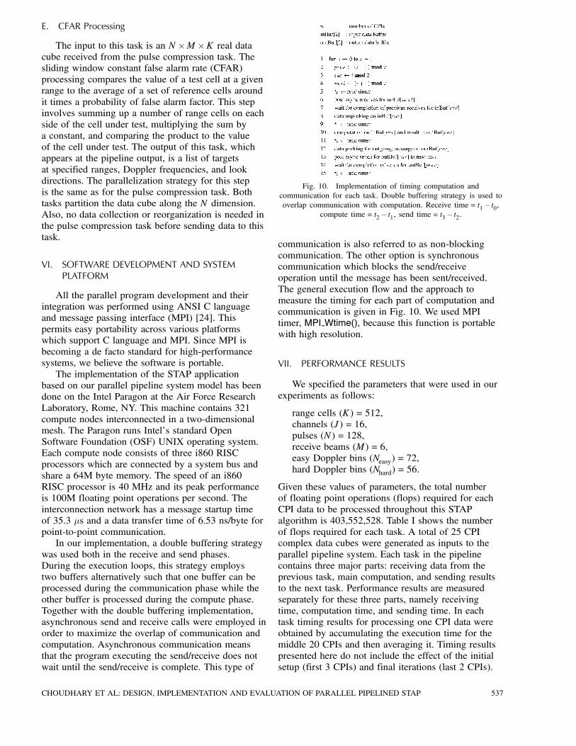
The input to this task is an N £M £K real datacube received from the pulse compression task. Thesliding window constant false alarm rate (CFAR)processing compares the value of a test cell at a givenrange to the average of a set of reference cells aroundit times a probability of false alarm factor. This stepinvolves summing up a number of range cells on eachside of the cell under test, multiplying the sum bya constant, and comparing the product to the valueof the cell under test. The output of this task, whichappears at the pipeline output, is a list of targetsat specified ranges, Doppler frequencies, and lookdirections. The parallelization strategy for this stepis the same as for the pulse compression task. Bothtasks partition the data cube along the N dimension.Also, no data collection or reorganization is needed inthe pulse compression task before sending data to thistask.
VI. SOFTWARE DEVELOPMENT AND SYSTEMPLATFORM
All the parallel program development and theirintegration was performed using ANSI C languageand message passing interface (MPI) [24]. Thispermits easy portability across various platformswhich support C language and MPI. Since MPI isbecoming a de facto standard for high-performancesystems, we believe the software is portable.The implementation of the STAP application
based on our parallel pipeline system model has beendone on the Intel Paragon at the Air Force ResearchLaboratory, Rome, NY. This machine contains 321compute nodes interconnected in a two-dimensionalmesh. The Paragon runs Intel’s standard OpenSoftware Foundation (OSF) UNIX operating system.Each compute node consists of three i860 RISCprocessors which are connected by a system bus andshare a 64M byte memory. The speed of an i860RISC processor is 40 MHz and its peak performanceis 100M floating point operations per second. Theinterconnection network has a message startup timeof 35:3 ¹s and a data transfer time of 6.53 ns/byte forpoint-to-point communication.In our implementation, a double buffering strategy
was used both in the receive and send phases.During the execution loops, this strategy employstwo buffers alternatively such that one buffer can beprocessed during the communication phase while theother buffer is processed during the compute phase.Together with the double buffering implementation,asynchronous send and receive calls were employed inorder to maximize the overlap of communication andcomputation. Asynchronous communication meansthat the program executing the send/receive does notwait until the send/receive is complete. This type of
Fig. 10. Implementation of timing computation andcommunication for each task. Double buffering strategy is used tooverlap communication with computation. Receive time = t1¡ t0,
compute time = t2¡ t1, send time = t3 ¡ t2.
communication is also referred to as non-blockingcommunication. The other option is synchronouscommunication which blocks the send/receiveoperation until the message has been sent/received.The general execution flow and the approach tomeasure the timing for each part of computation andcommunication is given in Fig. 10. We used MPItimer, MPI Wtime(), because this function is portablewith high resolution.
VII. PERFORMANCE RESULTS
We specified the parameters that were used in ourexperiments as follows:
range cells (K) = 512,channels (J) = 16,pulses (N) = 128,receive beams (M) = 6,easy Doppler bins (Neasy) = 72,hard Doppler bins (Nhard) = 56.
Given these values of parameters, the total numberof floating point operations (flops) required for eachCPI data to be processed throughout this STAPalgorithm is 403,552,528. Table I shows the numberof flops required for each task. A total of 25 CPIcomplex data cubes were generated as inputs to theparallel pipeline system. Each task in the pipelinecontains three major parts: receiving data from theprevious task, main computation, and sending resultsto the next task. Performance results are measuredseparately for these three parts, namely receivingtime, computation time, and sending time. In eachtask timing results for processing one CPI data wereobtained by accumulating the execution time for themiddle 20 CPIs and then averaging it. Timing resultspresented here do not include the effect of the initialsetup (first 3 CPIs) and final iterations (last 2 CPIs).
CHOUDHARY ET AL: DESIGN, IMPLEMENTATION AND EVALUATION OF PARALLEL PIPELINED STAP 537

Fig. 11. Performance and speedup of computation time as function of number of compute nodes for all tasks.
TABLE INumber of Floating Point Operations for PRI-StaggeredPost-Doppler STAP Algorithm to Process One CPI Data
A. Computation Costs
The task of computing hard weights is the mostcomputationally demanding task. The Doppler filterprocessing task is the second most demanding task.Naturally, more compute nodes are assigned to thesetwo tasks in order to obtain a good performance.For each task in the STAP algorithm, parallelizationwas done by evenly dividing the computational loadacross the compute nodes assigned. Since there isno intratask data dependency, no inter-processorcommunication occurs within any single task in thepipeline. Another way to view this is that intrataskcommunication is moved to the beginning of each taskwithin the data redistribution step. Fig. 11 gives the
computation performance results as functions of thenumbers of nodes and the corresponding speedup onthe AFRL Intel Paragon. For each task, we obtainedlinear speedups.
B. Intertask Communication
Intertask communication refers to thecommunication between the sending and receiving(distinct and parallel) tasks. This communicationcost depends on both the processor assignment foreach task as well as on the volume and extent of datareorganization. Tables II—VI present the intertaskcommunication timing results. Each table considerspairs of tasks where the number of compute nodesfor both tasks are varied. In some cases timing resultsshown in the tables contain idle time for waiting forthe corresponding task to complete. This happenswhen the receiving task’s computation part of thereceiving task completes before the sending task hasgenerated data to send.From most of the results (Tables II—VI) the
following important observations can be made.First, when the number of nodes is unbalanced (e.g.,sending task has a small number of nodes whilethe receiving task has a large number of nodes),the communication performance is not very good.Second, as the number of nodes is increased in thesending and receiving tasks, communication scales
538 IEEE TRANSACTIONS ON AEROSPACE AND ELECTRONIC SYSTEMS VOL. 36, NO. 2 APRIL 2000
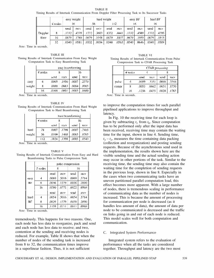
TABLE IITiming Results of Intertask Communication From Doppler Filter Processing Task to Its Successor Tasks
Note: Time in seconds.
TABLE IIITiming Results of Intertask Communication From Easy Weight
Computation Task to Easy Beamforming Task
Note: Time in seconds.
TABLE IVTiming Results of Intertask Communication From Hard Weight
Computation Task to Hard Beamforming Task
Note: Time in seconds.
TABLE VTiming Results of Intertask Communication From Easy and Hard
Beamforming Tasks to Pulse Compression Task
Note: Time in seconds.
tremendously. This happens for two reasons. One,each node has less data to reorganize, pack and sendand each node has less data to receive; and two,contention at the sending and receiving nodes isreduced. For example, Table II shows that when thenumber of nodes of the sending task is increasedfrom 8 to 32, the communication times improvein a superlinear fashion. Thus, it is not sufficient
TABLE VITiming Results of Intertask Communication From Pulse
Compression Task to CFAR Processing Task
Note: Time in seconds.
to improve the computation times for such parallelpipelined applications to improve throughput andlatency.In Fig. 10 the receiving time for each loop is
given by subtracting t1 from t0. Since computationhas to be performed only after the input data hasbeen received, receiving time may contain the waitingtime for the input, shown in line 4. Sending time,t3¡ t2, measures the time containing data packing(collection and reorganization) and posting sendingrequests. Because of the asynchronous send used inthe implementation, the results shown here are thevisible sending time and the actual sending actionmay occur in other portions of the task. Similar to thereceiving time, the sending time may also contain thewaiting time for the completion of sending requestsin the previous loop, shown in line 8. Especially inthe cases when two communicating tasks have anuneven partitioned parallel computation load, thiseffect becomes more apparent. With a large numberof nodes, there is tremendous scaling in performanceof communicating data as the number of nodes isincreased. This is because the amount of processingfor communication per node is decreased (as ithandles less amount of data), the amount of data pernode to be communicated is decreased and the trafficon links going in and out of each node is reduced.This model scales well for both computation andcommunication.
C. Integrated System Performance
Integrated system refers to the evaluation ofperformance when all the tasks are consideredtogether. Throughput and latency are the two most
CHOUDHARY ET AL: DESIGN, IMPLEMENTATION AND EVALUATION OF PARALLEL PIPELINED STAP 539
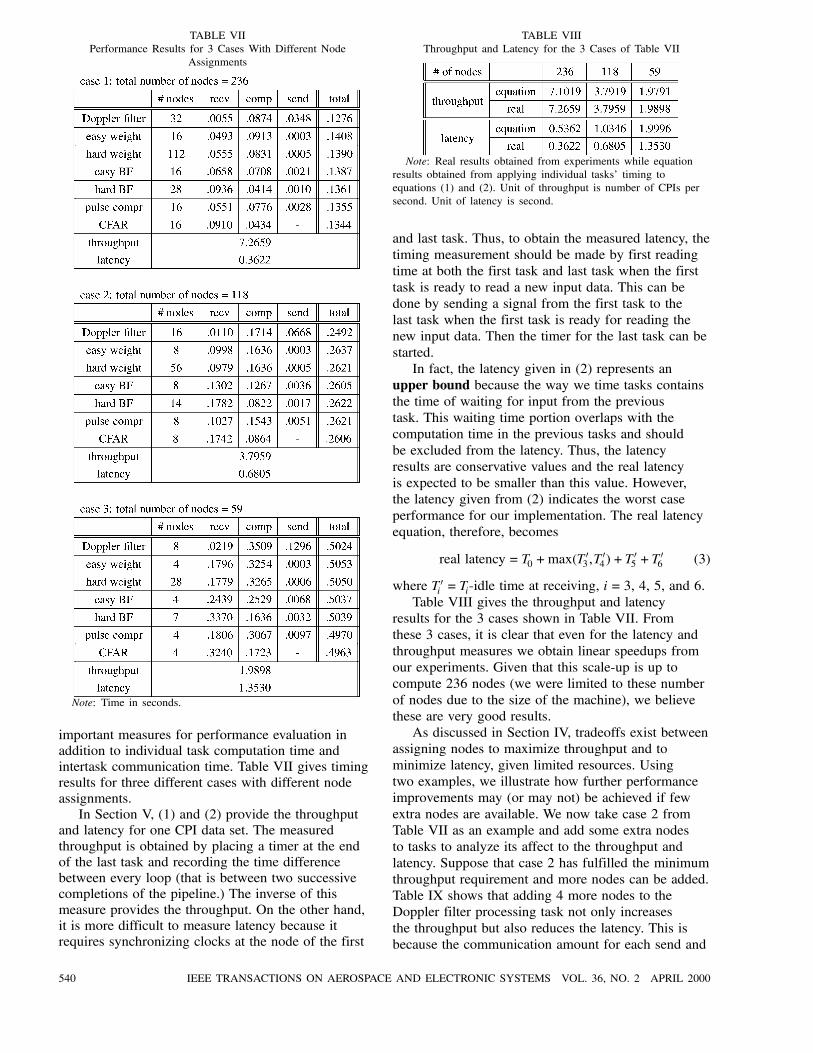
TABLE VIIPerformance Results for 3 Cases With Different Node
Assignments
Note: Time in seconds.
important measures for performance evaluation inaddition to individual task computation time andintertask communication time. Table VII gives timingresults for three different cases with different nodeassignments.In Section V, (1) and (2) provide the throughput
and latency for one CPI data set. The measuredthroughput is obtained by placing a timer at the endof the last task and recording the time differencebetween every loop (that is between two successivecompletions of the pipeline.) The inverse of thismeasure provides the throughput. On the other hand,it is more difficult to measure latency because itrequires synchronizing clocks at the node of the first
TABLE VIIIThroughput and Latency for the 3 Cases of Table VII
Note: Real results obtained from experiments while equationresults obtained from applying individual tasks’ timing toequations (1) and (2). Unit of throughput is number of CPIs persecond. Unit of latency is second.
and last task. Thus, to obtain the measured latency, thetiming measurement should be made by first readingtime at both the first task and last task when the firsttask is ready to read a new input data. This can bedone by sending a signal from the first task to thelast task when the first task is ready for reading thenew input data. Then the timer for the last task can bestarted.In fact, the latency given in (2) represents an
upper bound because the way we time tasks containsthe time of waiting for input from the previoustask. This waiting time portion overlaps with thecomputation time in the previous tasks and shouldbe excluded from the latency. Thus, the latencyresults are conservative values and the real latencyis expected to be smaller than this value. However,the latency given from (2) indicates the worst caseperformance for our implementation. The real latencyequation, therefore, becomes
real latency = T0 +max(T03 ,T
04)+T
05 +T
06 (3)
where T0i = Ti-idle time at receiving, i= 3, 4, 5, and 6.Table VIII gives the throughput and latency
results for the 3 cases shown in Table VII. Fromthese 3 cases, it is clear that even for the latency andthroughput measures we obtain linear speedups fromour experiments. Given that this scale-up is up tocompute 236 nodes (we were limited to these numberof nodes due to the size of the machine), we believethese are very good results.As discussed in Section IV, tradeoffs exist between
assigning nodes to maximize throughput and tominimize latency, given limited resources. Usingtwo examples, we illustrate how further performanceimprovements may (or may not) be achieved if fewextra nodes are available. We now take case 2 fromTable VII as an example and add some extra nodesto tasks to analyze its affect to the throughput andlatency. Suppose that case 2 has fulfilled the minimumthroughput requirement and more nodes can be added.Table IX shows that adding 4 more nodes to theDoppler filter processing task not only increasesthe throughput but also reduces the latency. This isbecause the communication amount for each send and
540 IEEE TRANSACTIONS ON AEROSPACE AND ELECTRONIC SYSTEMS VOL. 36, NO. 2 APRIL 2000
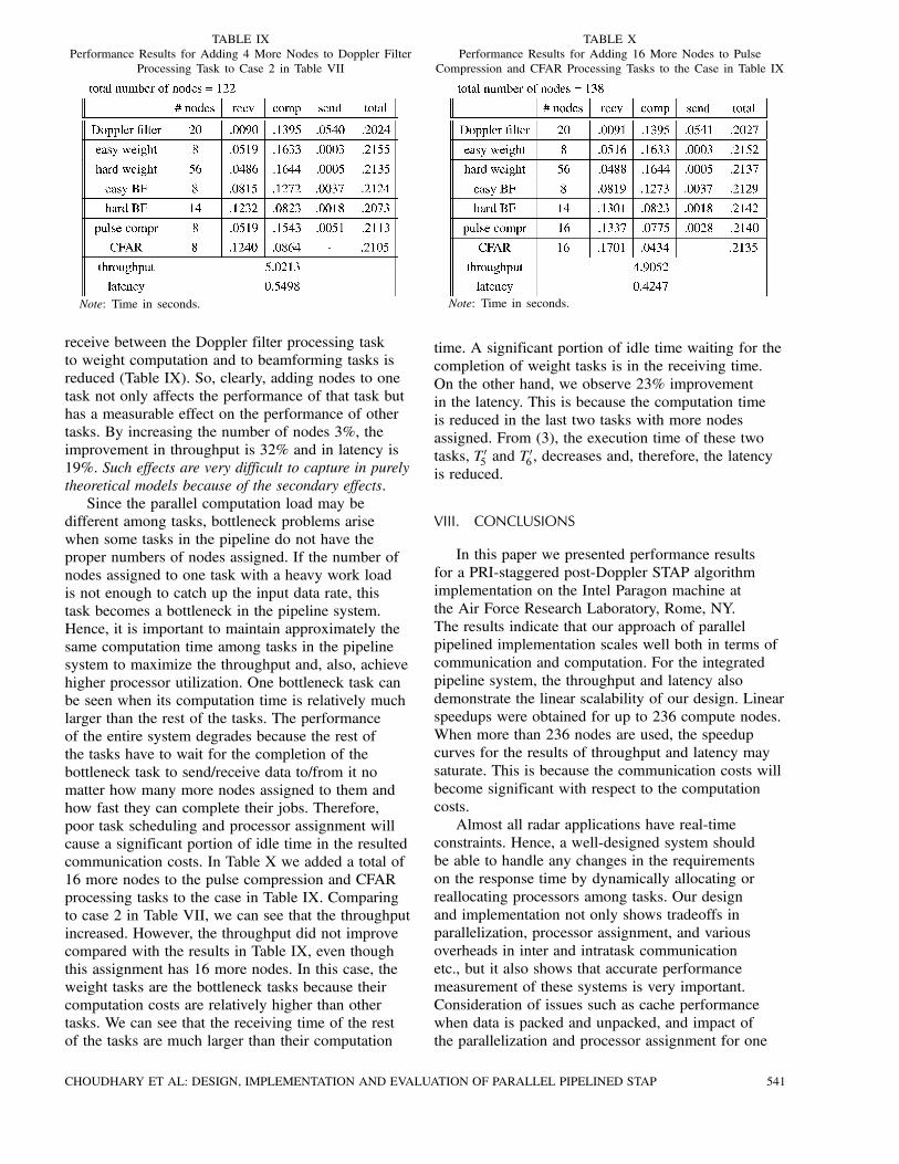
TABLE IXPerformance Results for Adding 4 More Nodes to Doppler Filter
Processing Task to Case 2 in Table VII
Note: Time in seconds.
receive between the Doppler filter processing taskto weight computation and to beamforming tasks isreduced (Table IX). So, clearly, adding nodes to onetask not only affects the performance of that task buthas a measurable effect on the performance of othertasks. By increasing the number of nodes 3%, theimprovement in throughput is 32% and in latency is19%. Such effects are very difficult to capture in purelytheoretical models because of the secondary effects.Since the parallel computation load may be
different among tasks, bottleneck problems arisewhen some tasks in the pipeline do not have theproper numbers of nodes assigned. If the number ofnodes assigned to one task with a heavy work loadis not enough to catch up the input data rate, thistask becomes a bottleneck in the pipeline system.Hence, it is important to maintain approximately thesame computation time among tasks in the pipelinesystem to maximize the throughput and, also, achievehigher processor utilization. One bottleneck task canbe seen when its computation time is relatively muchlarger than the rest of the tasks. The performanceof the entire system degrades because the rest ofthe tasks have to wait for the completion of thebottleneck task to send/receive data to/from it nomatter how many more nodes assigned to them andhow fast they can complete their jobs. Therefore,poor task scheduling and processor assignment willcause a significant portion of idle time in the resultedcommunication costs. In Table X we added a total of16 more nodes to the pulse compression and CFARprocessing tasks to the case in Table IX. Comparingto case 2 in Table VII, we can see that the throughputincreased. However, the throughput did not improvecompared with the results in Table IX, even thoughthis assignment has 16 more nodes. In this case, theweight tasks are the bottleneck tasks because theircomputation costs are relatively higher than othertasks. We can see that the receiving time of the restof the tasks are much larger than their computation
TABLE XPerformance Results for Adding 16 More Nodes to Pulse
Compression and CFAR Processing Tasks to the Case in Table IX
Note: Time in seconds.
time. A significant portion of idle time waiting for thecompletion of weight tasks is in the receiving time.On the other hand, we observe 23% improvementin the latency. This is because the computation timeis reduced in the last two tasks with more nodesassigned. From (3), the execution time of these twotasks, T05 and T
06 , decreases and, therefore, the latency
is reduced.
VIII. CONCLUSIONS
In this paper we presented performance resultsfor a PRI-staggered post-Doppler STAP algorithmimplementation on the Intel Paragon machine atthe Air Force Research Laboratory, Rome, NY.The results indicate that our approach of parallelpipelined implementation scales well both in terms ofcommunication and computation. For the integratedpipeline system, the throughput and latency alsodemonstrate the linear scalability of our design. Linearspeedups were obtained for up to 236 compute nodes.When more than 236 nodes are used, the speedupcurves for the results of throughput and latency maysaturate. This is because the communication costs willbecome significant with respect to the computationcosts.Almost all radar applications have real-time
constraints. Hence, a well-designed system shouldbe able to handle any changes in the requirementson the response time by dynamically allocating orreallocating processors among tasks. Our designand implementation not only shows tradeoffs inparallelization, processor assignment, and variousoverheads in inter and intratask communicationetc., but it also shows that accurate performancemeasurement of these systems is very important.Consideration of issues such as cache performancewhen data is packed and unpacked, and impact ofthe parallelization and processor assignment for one
CHOUDHARY ET AL: DESIGN, IMPLEMENTATION AND EVALUATION OF PARALLEL PIPELINED STAP 541

Fig. 12. Conventional least squares processing.
task on another task are crucial. This is normally noteasily captured in theoretical models. In the future weplan to incorporate further optimizations includingmultithreading, multiple pipelines, and multipleprocessors on each compute node.
APPENDIX A. SPACE-TIME ADAPTIVE PROCESSINGWITH MAINBEAM CONSTRAINT
The STAP problem can be formulated as a leastsquares minimization of the clutter response. Thisapproach is desirable from a computational standpoint,as it is not necessary to produce an estimate ofthe clutter covariance matrix, which is an order n3
operation. In the least squares approach, a matrixM is constructed from snapshots of the array dataafter Doppler processing, and a weight vector w iscomputed which minimizes the norm of the productvector Mw. The snapshots are samples of data fromeach array element taken at range cells adjacent tothe test cell, and also from multiple CPIs whichare decorrelated across time. Typically a beamconstraint, such as a requirement for unit response inthe direction of the desired target, is added to rule outthe trivial solution, w= 0. As illustrated in Fig. 12,the weight vector is computed by multiplying thepseudoinverse of M times a unit vector.While assuring a non-zero solution for the weights,
the conventional beam constraint placed on the leastsquares problem as formulated above often producesan adapted pattern with a highly distorted mainbeamwith a peak response far removed from thetarget of interest. The algorithm that was formulatedand implemented here is a constrained version ofthe least squares problem. Given a steering vectorws we seek a weight vector w that minimizes theclutter response while maintaining a close similaritybetween w and ws. This condition is specified byaugmenting the data matrix M with an identity matrixas depicted in Fig. 13. The product of the identitymatrix and the solution vector w is set to a scalarmultiple of the steering vector ws. The least squaressolution is a compromise between clutter rejection
Fig. 13. Beam constrained least squares processing.
and preservation of mainbeam shape. In practice,only slight modifications of the weight vector arerequired to move spatial nulls into the clutter region,for clutter returns that are outside of the mainbeam.Thus, preservation of mainbeam shape requires onlya slight reduction of clutter rejection performance,and is often offset by an increase in array gain on thedesired target. As shown in Fig. 13, the preservationof main beam shape is controlled by scalar k. Thechoice of k directs the least squares solution for wto adhere more closely to the steering vector whenk is large, and emphasize clutter cancellation at theexpense of beam shape when k is small. Since k isvariable depending on operating requirements, wenormalize the resulting weight vector to unit length.There is a computational advantage of the
constrained technique of Fig. 13 over that of Fig. 12for systems that utilize multiple beam steering. Sincethe steering vector ws appears only on the right sideof the equation, and matrix M is independent of themainbeam pointing angle, the QR factorization of Mneeds be performed only once for a given data set.Multiple weight vectors can be computed for differentsteering vector choices by multiplying the same matrixpseudoinverse or QR factorization by several choicesof constraint vectors.
APPENDIX B. MATLAB VERSION OF RT-MCARMPROCESSING ALGORITHM
542 IEEE TRANSACTIONS ON AEROSPACE AND ELECTRONIC SYSTEMS VOL. 36, NO. 2 APRIL 2000

CHOUDHARY ET AL: DESIGN, IMPLEMENTATION AND EVALUATION OF PARALLEL PIPELINED STAP 543

544 IEEE TRANSACTIONS ON AEROSPACE AND ELECTRONIC SYSTEMS VOL. 36, NO. 2 APRIL 2000
ACKNOWLEDGMENTS
We acknowledge the use of the Intel Paragon atCaltech for the initial development.
REFERENCES
[1] Linderman, M., and Linderman, R. (1998)Real-time STAP demonstration on an embedded highperformance computer.IEEE AES Systems Magazine (Mar. 1998), 15—21.
[2] Brown, R., and Linderman, R. (1997)Algorithm development for an airborne real-time STAPdemonstration.In Proceedings of the IEEE National Radar Conference,1997.
[3] Little, M., and Berry, W. (1997)Real-time multi-channel airborne radar measurements.In Proceedings of the IEEE National Radar Conference,1997.
[4] Kumar, V., Grama, A., Gupta, A., and Karypis, G. (1994)Introduction to Parallel Computing: Design and Analysis ofAlgorithms.Benjamin-Cummings, 1994.
[5] Fox, G., Johnson, M., Lyzenga, G., Otto, S., Salmon, J., andWalker, D. (1990)Solving Problems on Concurrent Processors.Englewood Cliffs, NJ: Prentice-Hall, 1990.
[6] Hwang, K. (1993)Advanced Computer Architecture: Parallelism, Scalability,Programmability.New York: McGraw-Hill, 1993.
[7] Golub, G., and Ortega, J. (1993)Scientific Computing: An Introduction with ParallelComputing.Boston: Academic Press, 1993.
[8] Xavier, C., and Iyengar, S. (1998)Introduction to Parallel Algorithms.New York: Wiley, 1998.
[9] Lebak, J., Durie, R., and Bojanczyk, A. (1996)Toward a portable parallel library for space-time adaptivemethods.Technical report CTC96TR242, Cornell Theory Center,June 1996.
[10] Olszanskyj, S., Lebak, J., and Bojanczyk, A. (1995)Parallel algorithms for space-time adaptive processing.In Proceedings of the International Parallel ProcessingSymposium (Apr. 1995), 77—81.
[11] Lim, Y., and Prasanna, V. (1996)Scalable portable implementations of space-time adaptiveprocessing.In Proceedings of the 10th International Conference onHigh Performance Computing (June 1996).
[12] Bhat, P., Lim, Y., and Prasanna, V. (1995)Issues in using heterogeneous HPC systems for embeddedreal time signal processing applications.In Proceedings of the 2nd International Workshop onReal-Time Computing Systems and Applications (Oct.1995).
[13] Lee, M., and Prasanna, V. (1997)High throughput-rate parallel algorithms for space timeadaptive processing.Presented at the 2nd International Workshop onEmbedded Systems and Applications, Apr. 1997.
[14] Martinez, D. (1999)Application of parallel processors to real-time sensorarray processing.Presented at the International Parallel ProcessingSymposium, Apr. 1999.
[15] Cain, K., Torres, J., and Williams, R. (1997)RT STAP: Real-time space-time adaptive processingbenchmark.Technical report 96B0000021, MITRE Corporation, Feb.1997.
[16] Brown, C., Flanzbaum, M., Games, R., and Ramsdell, J.(1994)Real-time embedded high performance computing:Application benchmarks.Technical report MTR94B145, MITRE Corporation, Oct.1994.
[17] Choudhary, A., and Patel, J. (1990)Parallel Architectures and Parallel Algorithms forIntegrated Vision Systems.Boston: Kluwer Academic Publishers, 1990.
[18] Choudhary, A., and Ponnusamy, R. (1992)Run-time data decomposition for parallel implementationof image processing and computer vision tasks.Journal of Concurrency, Practice and Experience, 4, 4(June 1992), 313—334.
[19] Choudhary, A., and Ponnusamy, R. (1992)Parallel implementation and evaluation of a motionestimation system algorithm using several datadecomposition strategies.Journal of Parallel and Distributed Computing, 14 (Jan.1992), 50—65.
[20] Thakur, R., Choudhary, A., and Ramanujam, J. (1996)Efficient algorithms for array redistribution.IEEE Transactions on Parallel and Distributed Systems, 6,7 (June 1996), 587—594.
[21] Berger, M., and Bokhari, S. (1987)A partitioning strategy for nonuniform problems onmultiprocessors.IEEE Transactions on Computers, C-36, 5 (May 1987),570—580.
[22] Berman, F., and Snyder, L. (1987)On mapping parallel algorithms into parallel architectures.Journal of Parallel and Distributed Computing, 4 (1987),439—458.
[23] Choudhary, A., Narahari, B., Nicol, D., and Simha, R.(1994)Optimal processor assignment for pipeline computations.IEEE Transactions on Parallel and Distributed Systems(Apr. 1994).
[24] Snir, M., et al. (1995)MPI the Complete Reference.Cambridge, MA: The MIT Press, 1995.
CHOUDHARY ET AL: DESIGN, IMPLEMENTATION AND EVALUATION OF PARALLEL PIPELINED STAP 545
Alok Choudhary received his Ph.D. from University of Illinois,Urbana-Champaign, in electrical and computer engineering, in 1989, M.S. fromUniversity of Massachusetts, Amherst, in 1986 and B.E. (Hons.) from BirlaInstitute of Technology and Science, Pilani, India in 1982.He has been an associate professor in the Electrical and Computer
Engineering Department at Northwestern University since September 1996.From 1989 to 1996 he was a faculty member in the ECE Department at SyracuseUniversity. He has worked in industry for computer consultants prior to 1984. Hismain research interests are in high-performance computing and communicationsystems and their applications in many domains of information processing,datamining, and scientific computing. In particular, his interests lie in the designand evaluation of architectures and software systems, high-performance servers,and input-output.Dr. Choudhary has served as program chair and general chair for several
conferences in parallel and high-performance computing areas. He received theNational Science Foundation’s Young Investigator Award in 1993 (1993—1999).He also received an IEEE Engineering Foundation award, an IBM FacultyDevelopment award and an Intel Research Council award.
Wei-keng Liao received a Ph.D. in computer and information science fromSyracuse University in 1999.He is a Research Assistant Professor in the Electrical and Computer
Engineering Department at Northwestern University. His research interests arein the area of high-performance computing, parallel I/O, and data managementfor large-scale scientific applications.
546 IEEE TRANSACTIONS ON AEROSPACE AND ELECTRONIC SYSTEMS VOL. 36, NO. 2 APRIL 2000

Donald D. Weiner (S’54–M’60–SM’90–F’94–LF’97) received the S.B.and S.M. degrees from the Massachusetts Institute of Technology, Cambridge,MA, in 1956 and 1958, respectively, and the Ph.D. from Purdue University, WestLafayette, IN, in 1964, all in electrical engineering.In 1964 he joined the Department of Electrical and Computer Engineering
at Syracuse University as an Assistant Professor where he was promoted toAssociated Professor in 1968 and Professor in 1974. He served as DepartmentChair from January 1993 through June 1996. Dr. Weiner became an EmeritusProfessor in 1998 and continues to serve the Department as a Research Professor.His present research deals with signal processing in an interference environmentincluding non-Gaussian noise. He has performed extensive work on theapplication of nonlinear systems analysis techniques and communications theoryto electromagnetic compatibility problems.Dr. Weiner has authored or coauthored over 40 journal articles, has presented
over 80 papers at various conferences and has delivered many invited lectures.He coauthored a book with J. Spina on The Sinusoidal Analysis and Modelingof Weakly Nonlinear Circuits, published by Van Nostrand Reinhold Company in1980. He also produced several films for the National Committee for ElectricalEngineering Films released by the Education Development Center in 1988. In1994 he was elected to the grade of Fellow in the IEEE for contributions to theanalysis of nonlinear effects in electromagnetic compatibility. He received theBest Paper Award of the IEEE Transactions on Electromagnetic Compatibility in1979, the General Electric Company Teaching Excellence Award in 1980, andthe IEEE Electromagnetic Compatibility Society Certificate of Achievement foroutstanding theoretical contributions to the analysis of nonlinear systems in 1985.
Pramod K. Varshney (S’72–M’77–SM’82–F’97) was born in Allahabad,India on July 1, 1952. He received the B.S. degree in electrical engineeringand computer science (with highest honors), and the M.S. and Ph.D. degrees inelectrical engineering from the University of Illinois at Urbana-Champaign in1972, 1974, and 1976, respectively.During 1972—1976, he held teaching and research assistantships at the
University of Illinois. Since 1976 he has been with Syracuse University, Syracuse,NY where he is currently a professor of Electrical Engineering and ComputerScience. He served as the Associate Chair of the department during 1993—1996.His current research interests are in distributed sensor networks and data fusion,detection and estimation theory, wireless communications, image processing,radar signal processing, and parallel algorithms.Dr. Varshney has authored and coauthored over sixty journal papers and over
one hundred thirty conference papers. He is the author of Distributed Detectionand Data Fusion, published by Springer-Verlag in 1997. He has consulted forGeneral Electric, Hughes, SCEEE, Kaman Sciences Corp., Andro Consulting,Stiefvater Consulting and Digicomp Research Corp. While at the Universityof Illinois, Dr. Varshney was a James Scholar, a Bronze Tablet Senior, and aFellow. He is a member of Tau Beta Pi and is the recipient of the 1981 ASEEDow Outstanding Young Faculty Award. He was elected to the grade of Fellowof the IEEE in 1997 for his contributions in the area of distributed detection anddata fusion. He was the guest editor of the special issue on data fusion of theProceedings of the IEEE, January 1997. He is on the editorial boards of ClusterComputing and Information Fusion. He is listed in Who’s Who in TechnologyToday and Outstanding Young Men of America.
CHOUDHARY ET AL: DESIGN, IMPLEMENTATION AND EVALUATION OF PARALLEL PIPELINED STAP 547
Richard W. Linderman (S’81–M’84–SM’90) received his B.S.E.E. degreefrom Cornell University, Ithaca, NY, in 1980; and his M.Eng. (EE) degreeand Ph.D. degrees from Cornell University, Ithaca, NY, in 1981 and 1984,respectively.He served as Chair, Signal Processing Technology at the U.S. Air Force
Research Laboratory (Rome Research Site) from 1988 to 1997. From 1984 to1988, he served on the graduate faculty of the Air Force Institute of Technologyteaching and conducting research in advanced computer architectures. Hisresearch interests include high performance computing architectures, VLSIarchitecture, advanced packaging, and digital signal processing applications.Dr. Linderman is an AFRL Fellow.
Mark H. Linderman (M’95) received his B.S.E.E. from the University ofDelaware, Newark, in 1986 and his M.Eng. in electrical engineering and Ph.D.degrees in 1990 and 1994, respectively from Cornell University, Ithaca, NY.He has worked as an engineer at HRB Singer in State College, PA. He
is currently the Technical Director at Air Force Research Laboratory, RomeResearch Site, IFTC Branch. He also is the Director of the High PerformanceComputing Facility at Rome Research Site. His research interests includecomputer aided-design tools for VLSI and computer architecture for signalprocessing.Dr. Linderman is a member of Eta Kappa Nu.
Russell D. Brown (SM’92–F’99) was born in Washington, DC on Sept. 5,1949. He received a B.S.E.E. degree in 1972, and M.S.E.E. in 1973, from theUniversity of Maryland, College Park, and Ph.D. in electrical engineering in 1995from Syracuse University, Syracuse, NY.From 1973 to 1978 he served as a Communications Electronics Officer for the
U.S. Air Force, and since 1978 has performed research in radar signal processingat the USAF Research Laboratory in Rome, NY.
548 IEEE TRANSACTIONS ON AEROSPACE AND ELECTRONIC SYSTEMS VOL. 36, NO. 2 APRIL 2000