design manual ductile iron
TRANSCRIPT

8/11/2019 Design Manual ductile iron
http://slidepdf.com/reader/full/design-manual-ductile-iron 1/138
KUBOTADUCTILE IRON PIPELINE
DESIGN MANUAL

8/11/2019 Design Manual ductile iron
http://slidepdf.com/reader/full/design-manual-ductile-iron 2/138
Index
1
Chapter 1 Foreword 4
Chapter 2 General Pipeline Design2-1 Types of Pipeline System 5
2-2 Pipeline Routing 6
2-3 Location and Laying Depth 7
Chapter 3 Layout of Pipeline3-1 General 9
3-2 Pipeline Facilities 9
Chapter 4 Pipe Diameter Selection4-1 General 14
4-2 Calculation of Head Loss 14
4-3 Example of Pipe Diameter Selection 25
4-4 Required Head and Power of Pump 26
4-5 Allowable Flow Velocity 29
4-6 Economical Pipe Diameters 29
4-7 Pipe Size for Distribution Network 30
Chapter 5 Water Hammer5-1 General 31
5-2 Simplified Calculation of Water Hammer 31
5-3 Prevention of Water Hammer 34
Chapter 6 Pipe Laying Conditions and External Loads
6-1 Earth Pressure due to Earth Cover
356-2 Earth Pressure due to Vehicle Load 37
Chapter 7 Design of Ductile Iron Pipe7-1 General 39
7-2 Design by ISO 10803 39
7-3 Kubota's Design Method 43
7-4 Example of Stress Analysis by Kubota Method 46
7-5 Diametral Deflection 47
Chapter 8 Thrust Anchoring8-1 General 48
8-2 Thrust Force by Internal Pressure 48
8-3 Anchoring by Concrete Blocks 49
8-4 Design of Concrete Block (Fittings encased)
8-5 Design of Concrete Block (Joints exposed) 53
8-6 Reference Tables 54
8-7 Thrust Anchoring by Restrained Joints 55
8-8 Restrained Length 57
8/11/2019 Design Manual ductile iron
http://slidepdf.com/reader/full/design-manual-ductile-iron 3/138
Index
2
Chapter 9 Corrosion Protection9-1 Internal Corrosion Protection 62
9-2 External Corrosion protection 63
9-3 Electrolytic Corrosion Protection 65
9-4 Cathodic Protection 65
Chapter 10 Pipeline Drawings10-1 Drawing Procedure of Piping Diagrams 67
10-2 Confirmation of Piping Conditions 68
10-3 Selection of Pipe and Fittings 69
10-4 Selection of Joints 69
10-5 Determination of Piping Composition 70
10-6 Determination of Bends 72
10-7 Determination of Piping Method 75
10-8Anchoring of Fittings
7610-9 Calculation of Pipe Cut Length 76
10-10 Use of Collar 77
10-11 Drawing Piping Diagrams 78
10-12 Bill of Quantity of Materials 78
Chapter 11 Installation11-1 General 81
11-2 Unloading from Truck 81
11-3 Storage 82
11-4 Trenching 82
11-5 Previous Excavation 83
11-6 Drainage of Trench 83
11-7 Pipe Laying 83
11-8 Valve Installation 84
11-9 Backfilling 84
Chapter 12 Jointing12-1 General 86
12-2 Type of Joint 86
12-3 Jointing Procedure 88
12-4 Deflection of Joints 94
12-5 Connection with Other Kinds of Pipe 97
12-6 Rubber Gasket 98
Chapter 13 Field Hydrostatic Test13-1 General 99
13-2 Flow Chart of Hydrostatic Test 99
13-3 Details of Each Step 100

8/11/2019 Design Manual ductile iron
http://slidepdf.com/reader/full/design-manual-ductile-iron 4/138
3
Chapter 14 Piping in Soft Ground
14-1 General 106
14-2 Investigation 106
14-3 Calculation of Settlement Amount 107
14-4 Straight Part of Pipeline 108
14-5 Self-anchoring Flexible Joint 112
14-6 Curved Parts of Pipeline 113
14-7 Precaution for Pipe Laying 113
Chapter 15 Piping under Special Conditions
15-1 Pipe Jacking 114
15-2 Piping on Slope 116
15-3 Aboveground Piping 117
15-4 Piping in Tunnel 118
15-5 River Crossing 11915-6 Railway and Road Crossing 120
15-7 Piping Inside Building 121
Chapter 16 Service Connections
16-1 General 124
16-2 Type of Service Connections 124
16-3 Direct Tapping 124
16-4 Tapping Saddle 125
16-5 Insertion of Tee into Existing Pipeline 125
Appendix 1 Conversion Table 128
Appendix 2 Pipe Arrangement in Chambers 130
Index

8/11/2019 Design Manual ductile iron
http://slidepdf.com/reader/full/design-manual-ductile-iron 5/138
Chapter1 Foreword
4
Ductile iron pipe is widely used for water supply pipelines, sewage pipelines,
industrial water pipelines, as well as agricultural water pipelines. Ductile iron
pipe is highly accepted because of its excellent strength, durability and laying
workability. However, appropriate piping design and installation are necessary
so that each of these characteristics may be used to full advantage.In this manual, as the “standard manual of piping design”, the design rocess
of ductile iron pipeline with examples and references is reviewed to aid in the
correct design of ductile iron pipelines. This booklet is not a textbook for
pipeline design but is intended to be a good practical guide to the design of
ductile iron pipelines, mainly for water works.Therefore, basic and theoretical
considerations will be left to standard books.
We hope this manual is helpful in some way to those who are dedicated to
the design of ductile iron pipelines.
Note: In this booklet, the dimensions and mechanical properties of ductile iron pipe and fittings are basedon International Standard (ISO) and British Standard (BS EN). For pipe and fittings of other
standards such as American Standard (ANSI) and Japanese Standard (JIS), it is necessary to
amend the dimensions and mechanical properties.

8/11/2019 Design Manual ductile iron
http://slidepdf.com/reader/full/design-manual-ductile-iron 6/138
Chapter 2 General Pipeline Design
5
2-1 Types of PipelineSystems
2-1-1 Gravity pipeline systemPipeline can work by gravity if its starting point is higher than the discharging point
plus the pressure drop resultant from frictional loss between these two points,
expressed in meter of water head.
This system has following characteristics:
(1) No power required
(2) Economy in facility cost, operation cost, maintenance cost and so forth
(3) Good serviceability with trouble-free operation
It is recommended to utilize this system as far as topographical conditions allow.
2-1-2 Pumping pipeline systemWhen the starting point is not high enough to give a gravity supply, it is necessary to
pump the water up to the discharge point.
This system has following characteristics:
(1) Easy control of water pressure
(2) Less influence by topographical conditions; consequently less limitation forpipeline routing
Gravity pipeline Fig. 2-1
Pumping pipeline Fig. 2-2
8/11/2019 Design Manual ductile iron
http://slidepdf.com/reader/full/design-manual-ductile-iron 7/138
Chapter 2 General Pipeline Design
6
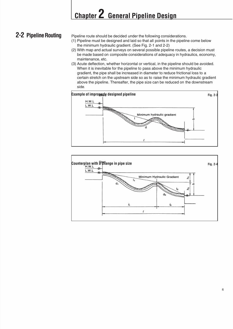
2-2 Pipeline Routing Pipeline route should be decided under the following considerations.
(1) Pipeline must be designed and laid so that all points in the pipeline come below
the minimum hydraulic gradient. (See Fig. 2-1 and 2-2)
(2) With map and actual surveys on several possible pipeline routes, a decision must
be made based on composite considerations of adequacy in hydraulics, economy,
maintenance, etc.
(3) Acute deflection, whether horizontal or vertical, in the pipeline should be avoided.
When it is inevitable for the pipeline to pass above the minimum hydraulic
gradient, the pipe shall be increased in diameter to reduce frictional loss to a
certain stretch on the upstream side so as to raise the minimum hydraulic gradient
above the pipeline. Thereafter, the pipe size can be reduced on the downstream
side.
Example of improperly designed pipeline Fig. 2-3
Counterplan with a change in pipe size Fig. 2-4
8/11/2019 Design Manual ductile iron
http://slidepdf.com/reader/full/design-manual-ductile-iron 8/138
Chapter 2 General Pipeline Design
7
2-3 Location andLaying Depth
(4) Dual-pipeline may be desirable in such sections where recovery of hydraulic
gradient seems difficult because of lack of connections with other pipelines in
emergencies, or throughout the entire route.
(5) Pipeline route should be decided so that the pipeline is not laid in unstable
locations as far as practical, such as where landslide might be expected, a steep
ascent and immediate foot and edge of slope, etc.
When it is unavoidable to lay pipeline in such areas, the following steps should be
taken along with a sufficient survey on the geological formation of the site in
question.
1) On a slope, along with adequate protection, a means of removing surface
water, seepage water and ground water should be constructed to prevent
erosion and collapse of the slope.
2) If pipeline must be laid quite close to or even in acutely sloped or landslide area,
the least possible amount of cutting and banking of earth should be allowed.
Banking or cutting of trees and bamboos often leads to collapse of sloped land.
In such locations, building of aqueduct with piers or abutments, or exposed
pipeline design is desirable instead of buried one.
3) For poor ground conditions such as embankments, reclaimed ground, etc,ground improvement or piling work will be required prior to pipe laying.
Foundation improvement techniques include replacing of soil, lowering of water
table by well-point in sandy ground, compaction of trench bedding, etc.
Technique to be employed must be selected after adequate geological surveys
and tests. Where a change in foundation conditions is possible and where
extreme uneven settlement is expected to result, a collar which has high
flexibility should be used for the irregular subsidence of the ground.
In a weak foundation, water table may be high in many cases, the pipe would
be liable to float because of buoyancy forces. Countermeasures against this
tendency should be devised. (See Table 11-2)
(6) Distribution pipeline should be designed, as a rule, to form a network. In areas
with remarkably large differences of ground elevation, the distribution system
should be divided into several pressure zones. This arrangement will ensure therequired pressure in each zone and the distribution pipeline is not stressed
beyond this rating.
In deciding the pipe location and its laying depth, the followings should be considered.
2-3-1 LocationIf pipe is to be laid under a public road, the location and depth of pipe laying should
be in conformity with all relevant laws as well as federal, state, and local regulations.
In particular, distribution pipeline should be, in principle, laid under public roads only
after giving thorough consideration to ensure it presents to future maintenanceproblem.
In general, the location and depth of underground facilities should correspond to the
category of road and should be agreed upon between the road authority and the
owners of the facilities.
2-3-2 Laying depthThe laying depth should be determined considering the surface load and other
factors.
The depth of underground facilities is specified in order to prevent the pipe from
damages by earth pressure and vehicle loads. Consequently the required depth will
vary depending on the soil, surface conditions, grade and class of the road, as well as
the structure and size of the pipe.

8/11/2019 Design Manual ductile iron
http://slidepdf.com/reader/full/design-manual-ductile-iron 9/138
Chapter 2 General Pipeline Design
8
Under public roads, pipe is generally laid with a standard earth cover depth of 1.2m.
However, where the standard depth cannot be maintained, it might be allowable to
reduce the earth cover to a minimum of 0.6m. In case of less than 0.6m, it is
recommended strengthening the pipe and protecting the pipe from damage by paving
the road with concrete slab on the road surface above the pipe, or by using a box- or
gate-type concrete rigid frame around the pipe.
In any case, the larger the size of pipe, the deeper the earth cover required. If pipe is
laid under a sidewalk, or if the site is for the exclusive use of waterlines where no
vehicular traffic is permitted, a shallow cover of earth is allowable. However, where
the water table is high and threatens to float the pipe, it should be laid with enough
earth cover to prevent floating. (See Table 11-2)
During pipe laying, stagnant water in the excavated trench may float the pipe,
therefore backfilling should be completed as soon as possible.
Where the surface load is light, the earth cover may be reduced. But the depth should
not be so shallow as to adversely affect the installation of fire hydrants or valves, the
connection of private sewers, or the installation of gas service pipe.
2-3-3 Distance from underground facilitiesWhen the pipe is buried across or close to other underground facilities, at least 0.3m
distance from them should be maintained. When there is no interspace between the
water main and other underground facilities, not only the maintenance and repairs of
the pipeline become difficult, but the concentrated load is likely to work around the
contact point, therefore, a minimal distance or interval at the time of pipe laying must
be maintained.
2-3-4 Laying in unsuitable areasWhen pipe is inevitably buried in unsuitable areas from the topographical point of
view, necessary steps to maintain soil stability must be employed after adequate
surveys. In situation where it is necessary to lay pipes in a location with unstable
foundation such as the site of possible landslide, acute slope, top of the slope, etc.,
adequate surveys to determine the soil conditions, geological formation, behavior ofunderground water, etc. should be conducted. Afterwards, the required protective
steps, including selection of laying condition and depth, landslide prevention,
foundation work, pipe protective devices, etc. should be carried out.
In particular, in the situation where small cracks permeate the ground and invite or
advance slope failure, the utmost attention should be paid to the execution of
protective work. When large size pipe is to be laid, in order that the pipe does not
interfere with groundwater flow, an infiltration pipe should be laid at right angles to the
main to facilitate flow of ground water.
2-3-5 Laying in cold regionsPipe laying depth in the cold regions should be larger than the freezing depth. In case
the laying depth cannot be determined, adequate protective steps such as use ofadiabatic mats should be considered.

8/11/2019 Design Manual ductile iron
http://slidepdf.com/reader/full/design-manual-ductile-iron 10/138
Chapter 3 Layout of Pipeline
9
3-1 General
3-2 Pipeline Facilities
The problems involved in surveying and planning the pipeline route are affected by
both the size of the pipe and its location. More attention to details and precautions is
necessary as the pipe size increases and when the pipeline passes from rural to
urban areas. In general, plan and profile together with certain other details are
necessary for any water pipeline route selection.
These should show:
1) Horizontal and vertical distances, either directly or by survey station and elevation
If slope distances are given, this fact should be stated.
2) Location of bends and their angles, both horizontal and vertical (points of
intersection preferred)
3) Angle of bends, degree or radius of curves, tangent distances on curves, or
external distances if clearance is required
4) Points of intersection with pipe centerline for tees or other branches, together with
direction (right or left, up or down) or deflection angle of flow viewed from inlet
end
5) Location and size of all valves, pumps or other on-line fittings
6) Location of adjacent or interfering installations or structures
7) Tie-ins with property lines, curb lines, road or street centerlines, and otherpertinent features necessary to define right-of-way and locate pipe centerline
clearly
8) Details or descriptions of all specials together with other required data
9) Details, dimensions, and class designation or other description of all flanges
10) Any special requirements affecting the manufacture of the pipe or installation
procedures
Investigation of soil conditions may be necessary to determine the external protective
coating requirements, excavation procedures, allowable bearing capacity of the
ground, or design of thrust blocks. The location of the water table may affect the
design and installation of the pipe. Soil boring may be desirable where large and
heavy water pipelines are involved.
Once the pipeline route and operation conditions are established, it is important to
choose and correctly install the various kinds of valves and other facilities which will
ensure the reliable and economical operation of the pipeline.
3-2-1 Air relief valveRemoval of air from the pipeline is the most important factor affecting the reliability
and stability of water supply.
1) Air relief valves should be installed either on the summit in the pipeline, or in
absence of a summit between two stop valves, directly below the stop valve
located higher.
The “summit” mentioned here does not mean the highest point throughout thepipeline, but rather local highest point such as in sub-section between two valves,
water-bridge pipe or aqueduct. Even when neither a summit point nor a concave
part exists between two stop valves and the distance is long, provision for air
relief valves at adequate intervals such as every 500m to 1km is recommended.
However, with distribution sub-mains, where there is a constant possibility of air
being released or introduced via service installations or fire hydrants, there is no
particular need for the installation of the air relief valve if air releases via fire
hydrants is possible.

8/11/2019 Design Manual ductile iron
http://slidepdf.com/reader/full/design-manual-ductile-iron 11/138
Chapter 3 Layout of Pipeline
10
2) Double-orifice air relief valve or rapid-exhaust air relief valve is recommended for
DN400 and larger pipes.
For DN800 and larger pipes, use of tees with DN600 flanged branch and flanged
cover incorporated with air relief valve would prove convenient from the
maintenance standpoint. Even for pipes smaller then DN400, use of double-orifice
air relief valve is recommended if the passage of air is considered.
If pipe size is exceptionally large, special devices should be considered.
3) With air relief valve, isolating valve should be installed, if necessary, for
convenience in replacement or repairs of the air relief valve.
4) If pipes are buried underground, a protecting valve box should be provided. When
valve box is installed in where groundwater table is high, connecting pipe of
sufficient height should also be installed to protect the air relief valve from
backflow of contaminated water. The valve box may be of reinforced concrete orreinforced concrete blocks with iron cover and should afford access to repairmen.
The foundation should be constructed so as to avoid the direct contact with the
main. (Refer to Appendix 2)
In cold regions, valve box cover should be of double wall construction to prevent
freezing of the valve, and the box should be filled with suitable thermal insulation
material.
3-2-2 Stop valveIt sometimes becomes necessary to stop the supply of water in the pipeline because
of service problems, repair work, draining for cleaning, branch connection work,
maintenance requirements, etc. An effort should be made to restrict the affected
service area to the minimum. For this reason, an adequate number and type of stopvalves such as gate (sluice) valves, butterfly valves, etc. must be provided in the
pipeline.
1) Stop valves should be provided so that the fewest possible number need to
function in order to limit the area affected by the shutdown of water supply as
small as possible.
It is recommended providing two stop valves at the branching points and three
valves at the intersections to be able to stop the flow at each pipeline. For a long
pipeline, installation of stop valve at every 1 km to 3 km is recommended to allow
for partial suspension of the service.
2) Stop valves should be installed at important inverted siphons, bridges, before and
after railroad crossing, blow-off pipes and in the connecting pipes to the
distribution pipeline.
Positions of valves Fig. 3-1
8/11/2019 Design Manual ductile iron
http://slidepdf.com/reader/full/design-manual-ductile-iron 12/138
Chapter 3 Layout of Pipeline
1
3) When the pressure difference is large at the both sides of the closed valve,
operation for opening and closing might become difficult. For this reason, it is
recommended providing a by-pass valve on the stop valve with pressure
difference of above 4 bar and pipes of above DN400. The by-pass valve should
be operated in advance of the main valve so that the pressure at both sides of
valve becomes equal and the main valve can be operated easily. Also by-pass
valve will help on a small scale to control the flow rate and pressure of the main.
4) Valves should be protected by valve box or valve chamber.
(Refer to Appendix 2)
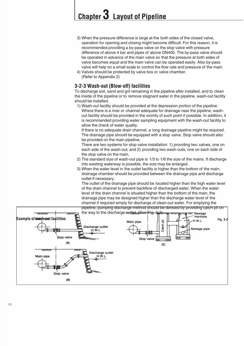
3-2-3 Wash-out (Blow-off) facilitiesTo discharge soil, sand and grit remaining in the pipeline after installed, and to clean
the inside of the pipeline or to remove stagnant water in the pipeline, wash-out facility
should be installed.
1) Wash-out facility should be provided at the depression portion of the pipeline.
Where there is a river or channel adequate for drainage near the pipeline, wash-
out facility should be provided in the vicinity of such point if possible. In addition, it
is recommended providing water sampling equipment with the wash-out facility toallow the check of water quality.
If there is no adequate drain channel, a long drainage pipeline might be required.
The drainage pipe should be equipped with a stop valve. Stop valve should also
be provided on the main pipeline.
There are two systems for stop valve installation: 1) providing two valves, one on
each side of the wash-out; and 2) providing two wash-outs, one on each side of
the stop valve on the main.
2) The standard size of wash-out pipe is 1/3 to 1/6 the size of the mains. If discharge
into existing waterway is possible, the size may be enlarged.
3) When the water level in the outlet facility is higher than the bottom of the main,
drainage chamber should be provided between the drainage pipe and discharge
outlet if necessary.
The outlet of the drainage pipe should be located higher than the high water levelof the drain channel to prevent backflow of discharged water. When the water
level of the drain channel is situated higher than the bottom of the main, the
drainage pipe may be designed higher than the discharge water level of the
channel if required simply for discharge of clean-out water. For emptying the
pipeline, pumping discharge method should be devised by providing catch pit on
the way to the discharge outlet. (See Fig. 3-2)
Example of wash-out facilities Fig. 3-2

8/11/2019 Design Manual ductile iron
http://slidepdf.com/reader/full/design-manual-ductile-iron 13/138
Chapter 3 Layout of Pipeline
12
4) The revetment near the discharge outlet should be thoroughly protected from
erosion and damage by discharged water.
If there is a fear of the area near the discharge outlet being eroded or broken up
by large amounts of discharged water, protection should be devised using
concrete structures, wire cylinders, gravel, etc. For temporary use, steel sheet
piling, rafted timber, etc. should be used. There is another method in which catch
pit is built of reinforced concrete. In such construction, the water discharged from
the wash-out is allowed to dash against the wall to kill the force of water. In this
case, the overflow outlet should be enlarged in width to the greatest possible
extent to reduce the flow rate.
It is recommended providing fences around the outlet facility for safety.
3-2-4 Pressure reducing valves and safety valves1) For connecting a pipeline between service areas with different pressures,
pressure reducing valve (or reducer valve) must be provided so that excessive
pressure will not cause problems in water system operation and maintenance, or
that such pressure will not exceed the allowed maximum pressure.
2) Pressure reducing valves must also be provided at pump outlets, and at spotswhere water hammer is likely to occur. However, no pressure reducing valve is
needed where other pressure controlling devices, e.g., tanks, etc. are installed.
3-2-5 Fire hydrants1) Fire hydrants should be provided in locations convenient for the fire fighting
activities, e.g. street intersections branches, etc., and especially where
distribution pipes converge and water collection is expected.
In addition to these locations, hydrants should be provided at certain intervals,
such as every 100 m to 200 m depending on the situation of buildings and houses
along the streets or road.
2) Single-jet hydrants should be installed on DN150 and larger pipes, and double-jet
hydrants on DN300 and larger pipes. However, even on pipes smaller than
DN150, double-jet hydrants can be used provided adequate function in thenetwork can be expected, when water pressure is high, or when large size pipe is
provided in the vicinity and the supply of fire fighting water is judged satisfactory.
Fire hydrant should be equipped with isolating valve in view of the need for
maintenance including shut-down of water supply for repairs, etc.
3) In the snowy regions, unless traffic will be interrupted frost-resistant surface type
hydrant should be provided. Also, in this case, for protection of freezing, non-
freezing type should be employed. If underground type is adopted, either hydrant
box must be designed with double covers or insulating material must be filled in
the box.
3-2-6 Flow meters and pressure gauges
1) It is recommended installing flow meter at the starting point of the pipeline tocheck the flow rate. The flow meter shall be capable of measuring and recording
the normal demand and the minimum and maximum demands.
2) Flow meter shall be equipped with devices for indicating, integrating and
recording.
3) It is recommended installing self-recording pressure gauges and flow meters, at
appropriate spots in service area, for effective and economical operation of the
pipeline system.

8/11/2019 Design Manual ductile iron
http://slidepdf.com/reader/full/design-manual-ductile-iron 14/138
Chapter 3 Layout of Pipeline
3
3-2-7 ManholesFor DN800 and larger pipeline, it is recommended providing manholes where needed
for pipe inside inspection and maintenance.
Manholes should be provided at locations where problems are liable to occur, such as
aqueducts, inverted siphons, stop valves, etc., and where there are obvious
topographical or geological variations and at other locations considered to be
required. Also where earth cover is deep, inspection and repair from pipe outside is
difficult, and providing manholes at these locations is in order.
Manhole should, in general, be DN600 in size and closed with blank flange,
incorporated usually with air relief valve. There is a possibility of manhole chamber
being filled with toxic gases or lack in oxygen, so prior to entering, atmospheric
condition in the manhole chamber must be checked with detectors.
8/11/2019 Design Manual ductile iron
http://slidepdf.com/reader/full/design-manual-ductile-iron 15/138
Chapter 4 Pipe Diameter Selection
14
4-1 General
4-2 Calculation ofHead Loss
The volume of water delivered through a pipeline depends on the following factors:
1) Head (or pressure) of water available at the source, i.e. pump or reservoir
2) Difference of elevation between source and discharge point
3) Diameter of pipeline
4) Friction head loss caused by pipeline
5) Friction head losses caused by fittings, valves, etc.
The diameter of the pipeline is thus selected based on the head (pressure) loss.
The head loss of the pipeline is expressed as a function of pipe diameter, pipeline
length and flow velocity of water in the pipeline by the general formula:
Where, h : Head loss (m)
L : Length of pipeline (m)D: Diameter of pipe (m)
(Normally nominal diameter presented in meter is used.)
V: Flow velocity (m/s)
g : Acceleration of gravity (= 9.8 m/s2)
f : Head loss coefficient
The coefficient “f” is a function of the flow velocity, the liquid conveyed and
characteristics of the pipeline (diameter and surface condition of the pipe).
There are numerous formulas for the calculation of “f”.
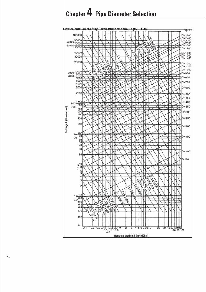
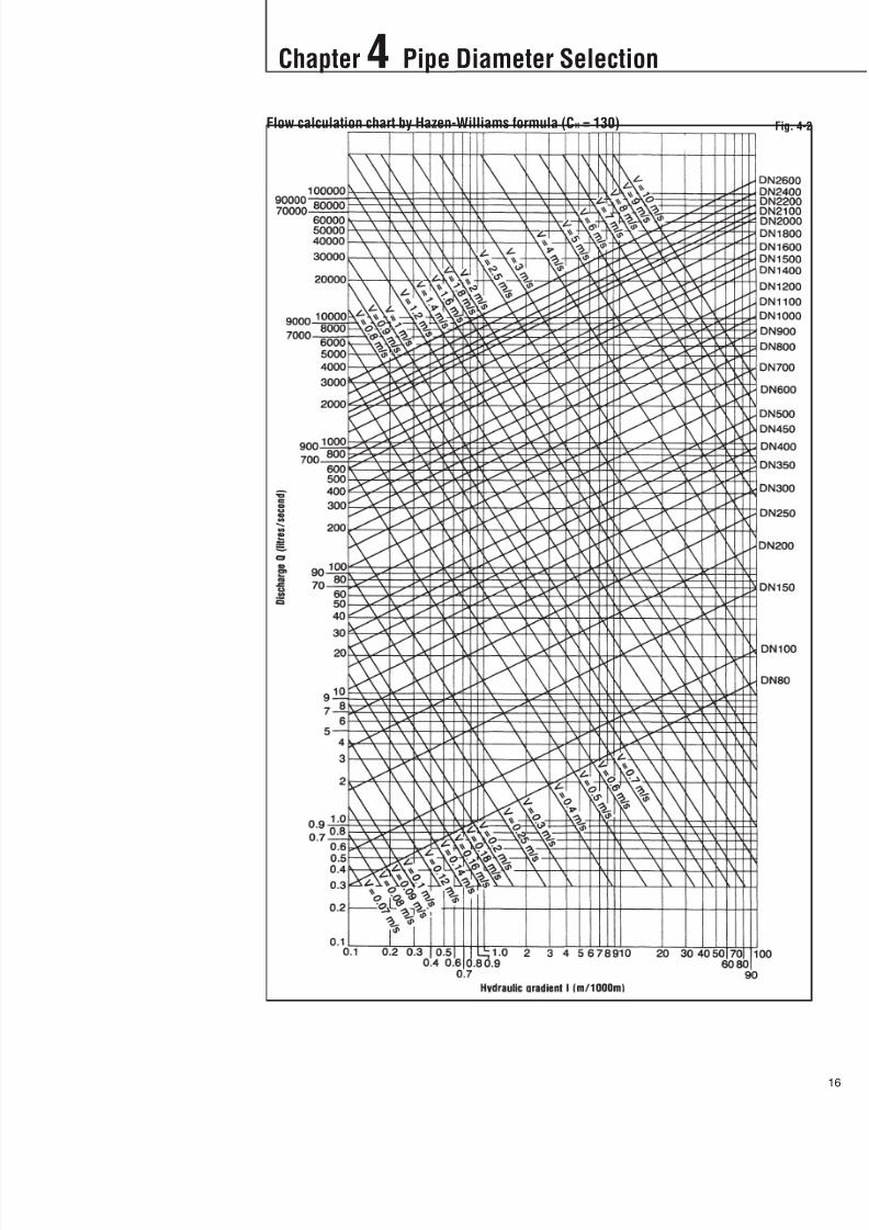
4-2-1 Hazen-Williams formulaFor water pipeline, Hazen-Williams formula is commonly used.
Where, CH : Coefficient
For cement mortar or epoxy lined ductile iron pipe, a CH value of 150 can
be used; however for design purpose, 130 is recommended, which
includes losses in fittings, valves and other facilities, plus some
allowance.
I : Hydraulic gradient (unit head loss of the pipeline) = h/L
Q : Flow volume (m3 /s)
Calculation charts by Hazen-Williams formula are shown inFig.4-1 and 4-2.
8/11/2019 Design Manual ductile iron
http://slidepdf.com/reader/full/design-manual-ductile-iron 16/138
Chapter 4 Pipe Diameter Selection
5
Flow calculation chart by Hazen-Williams formula (CH = 150) Fig. 4-1
8/11/2019 Design Manual ductile iron
http://slidepdf.com/reader/full/design-manual-ductile-iron 17/138
Chapter 4 Pipe Diameter Selection
16
Flow calculation chart by Hazen-Williams formula (CH = 130) Fig. 4-2
8/11/2019 Design Manual ductile iron
http://slidepdf.com/reader/full/design-manual-ductile-iron 18/138
Chapter 4 Pipe Diameter Selection
7
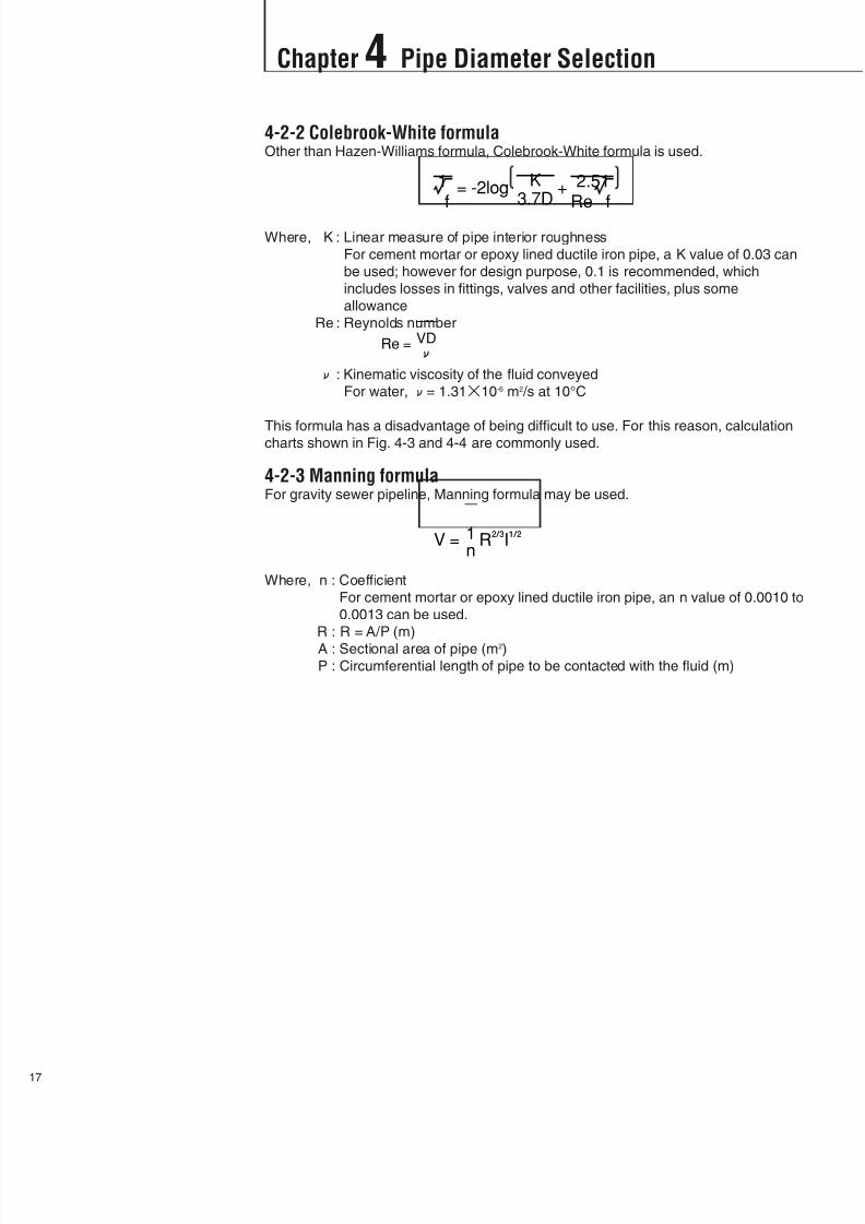
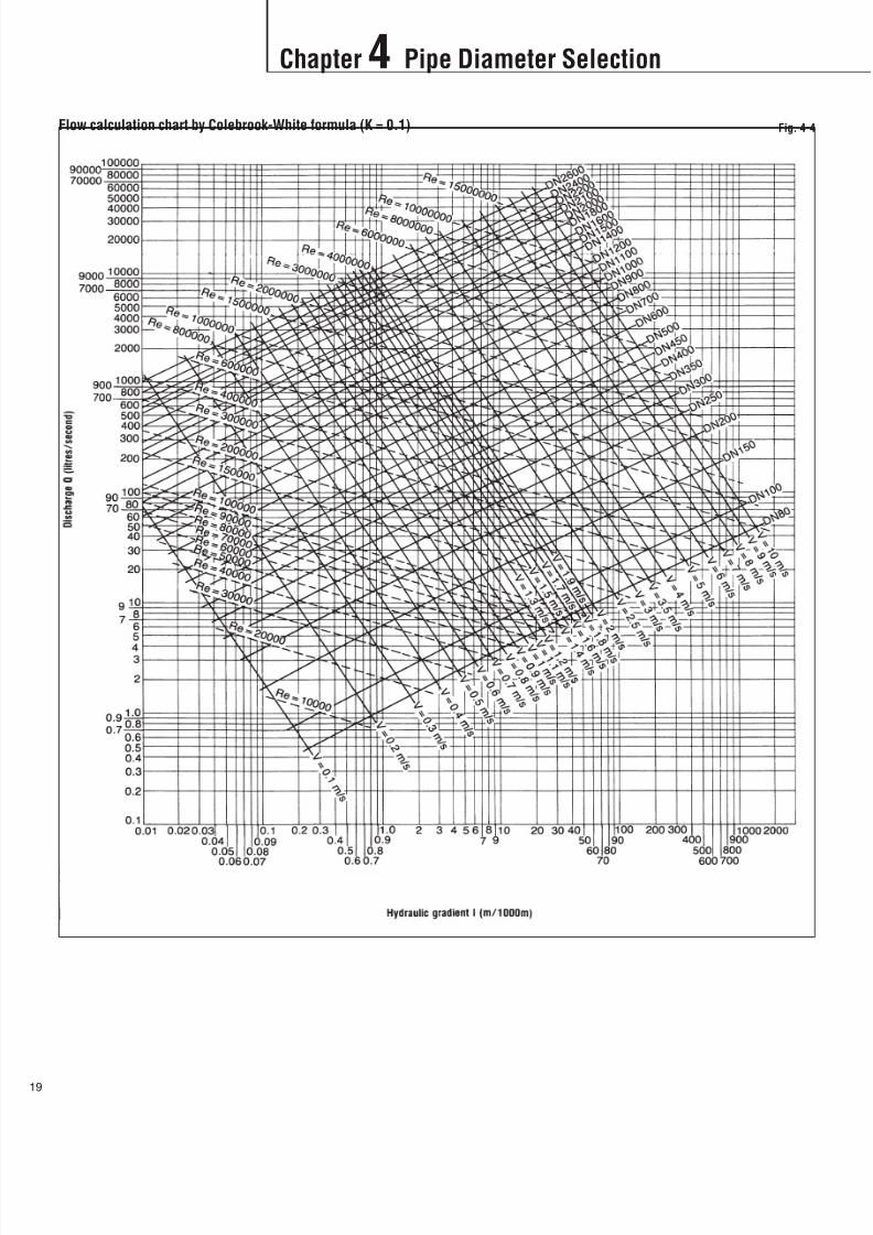
4-2-2 Colebrook-White formulaOther than Hazen-Williams formula, Colebrook-White formula is used.
Where, K : Linear measure of pipe interior roughness
For cement mortar or epoxy lined ductile iron pipe, a K value of 0.03 can
be used; however for design purpose, 0.1 is recommended, which
includes losses in fittings, valves and other facilities, plus some
allowance
Re : Reynolds number
: Kinematic viscosity of the fluid conveyed
For water,= 1.3110-6 m2 /s at 10°C
This formula has a disadvantage of being difficult to use. For this reason, calculationcharts shown in Fig. 4-3 and 4-4 are commonly used.
4-2-3 Manning formulaFor gravity sewer pipeline, Manning formula may be used.
Where, n : Coefficient
For cement mortar or epoxy lined ductile iron pipe, an n value of 0.0010 to
0.0013 can be used.
R : R = A/P (m)
A : Sectional area of pipe (m2)P : Circumferential length of pipe to be contacted with the fluid (m)

8/11/2019 Design Manual ductile iron
http://slidepdf.com/reader/full/design-manual-ductile-iron 19/138
Chapter 4 Pipe Diameter Selection
18
Flow calculation chart by Colebrook-White formula (K = 0.03) Fig. 4-3
8/11/2019 Design Manual ductile iron
http://slidepdf.com/reader/full/design-manual-ductile-iron 20/138
Chapter 4 Pipe Diameter Selection
9
Flow calculation chart by Colebrook-White formula (K = 0.1) Fig. 4-4
8/11/2019 Design Manual ductile iron
http://slidepdf.com/reader/full/design-manual-ductile-iron 21/138
Chapter 4 Pipe Diameter Selection
20
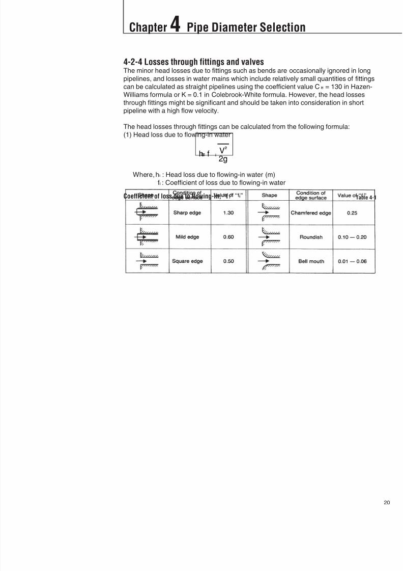
4-2-4 Losses through fittings and valvesThe minor head losses due to fittings such as bends are occasionally ignored in long
pipelines, and losses in water mains which include relatively small quantities of fittings
can be calculated as straight pipelines using the coefficient value CH = 130 in Hazen-
Williams formula or K = 0.1 in Colebrook-White formula. However, the head losses
through fittings might be significant and should be taken into consideration in short
pipeline with a high flow velocity.
The head losses through fittings can be calculated from the following formula:
(1) Head loss due to flowing-in water
Where,hi : Head loss due to flowing-in water (m)
fi : Coefficient of loss due to flowing-in water
Coefficient of loss due to flowing-in, “f i”Table 4-1

8/11/2019 Design Manual ductile iron
http://slidepdf.com/reader/full/design-manual-ductile-iron 22/138
Chapter 4 Pipe Diameter Selection
1
(2) Head loss due to bend
Where,hb : Head loss due to bend (m)
fb : Coefficient of loss. According to Weisbach;
Notes: (1) The Weisbach formula well conforms with the smooth round pipe of R/r<6, but when it is rough
the value becomes about double what is obtained from the formula.
(2) The “fb” is inclusive of the friction loss of the bent parts.
Fig. 4-5
Coefficient of loss, “fb” at=90° Fig. 4-6

8/11/2019 Design Manual ductile iron
http://slidepdf.com/reader/full/design-manual-ductile-iron 23/138
Chapter 4 Pipe Diameter Selection
22
(3) Head loss due to change in section or diameter
1) In the case of gradual expansion
Where,hge : Head loss due to gradual expansion (m)
fge : Coefficient of loss
V1 : Flow velocity before gradual expansion (m/s)
V2 : Flow velocity after gradual expansion (m/s)
: Gradual expansion angle (degree)
Fig. 4-7
Coefficient of loss due to gradual expansion, fge Table 4-2
8/11/2019 Design Manual ductile iron
http://slidepdf.com/reader/full/design-manual-ductile-iron 24/138
Chapter 4 Pipe Diameter Selection
3
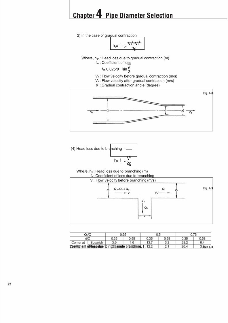
2) In the case of gradual contraction
Where, hgc : Head loss due to gradual contraction (m)
fgc : Coefficient of loss
V1 : Flow velocity before gradual contraction (m/s)
V2 : Flow velocity after gradual contraction (m/s)
: Gradual contraction angle (degree)
(4) Head loss due to branching
Where, hn : Head loss due to branching (m)fn : Coefficient of loss due to branching
V : Flow velocity before branching (m/s)
Fig. 4-8
Fig. 4-9
Coefficient of loss due to right angle branching, fn Table 4-3
8/11/2019 Design Manual ductile iron
http://slidepdf.com/reader/full/design-manual-ductile-iron 25/138
Chapter 4 Pipe Diameter Selection
24
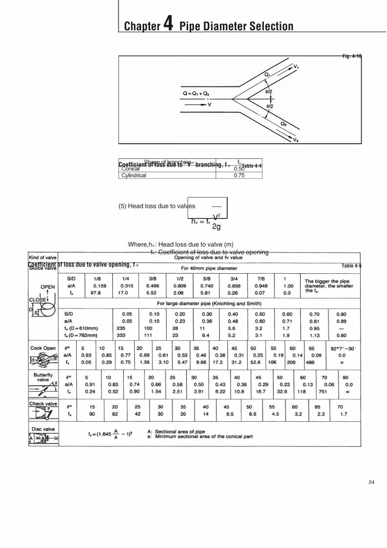
(5) Head loss due to valves
Where,hv : Head loss due to valve (m)
fv : Coefficient of loss due to valve opening
Fig. 4-10
Coefficient of loss due to “Y” branching, fn Table 4-4
Coefficient of loss due to valve opening, fV Table 4-5
8/11/2019 Design Manual ductile iron
http://slidepdf.com/reader/full/design-manual-ductile-iron 26/138
Chapter 4 Pipe Diameter Selection
5
4-3Examples of PipeDiameter Selection
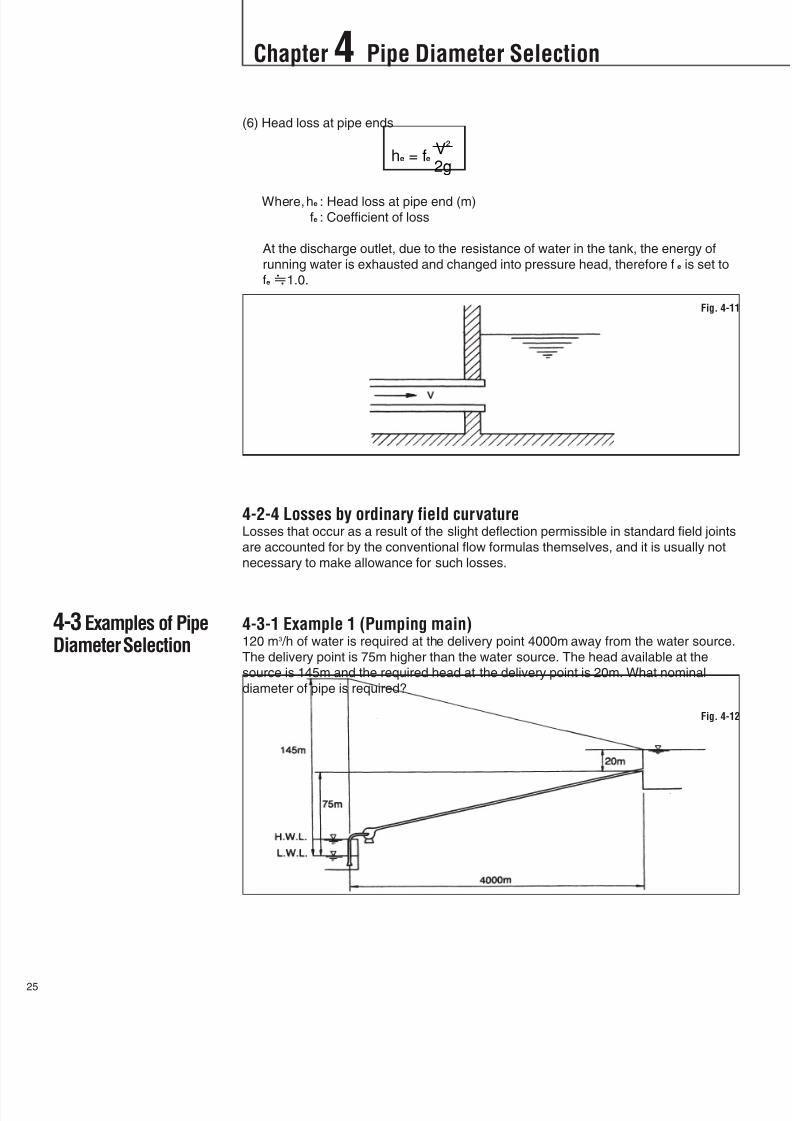
(6) Head loss at pipe ends
Where,he : Head loss at pipe end (m)
fe : Coefficient of loss
At the discharge outlet, due to the resistance of water in the tank, the energy of
running water is exhausted and changed into pressure head, therefore fe is set to
fe 1.0.
4-2-4 Losses by ordinary field curvatureLosses that occur as a result of the slight deflection permissible in standard field joints
are accounted for by the conventional flow formulas themselves, and it is usually not
necessary to make allowance for such losses.
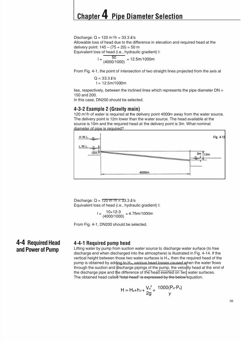
4-3-1 Example 1 (Pumping main)120 m3 /h of water is required at the delivery point 4000m away from the water source.
The delivery point is 75m higher than the water source. The head available at the
source is 145m and the required head at the delivery point is 20m. What nominal
diameter of pipe is required?
Fig. 4-11
Fig. 4-12
8/11/2019 Design Manual ductile iron
http://slidepdf.com/reader/full/design-manual-ductile-iron 27/138
Chapter 4 Pipe Diameter Selection
26
4-4 Required Headand Power of Pump
Discharge: Q = 120 m3 /h = 33.3R /s
Allowable loss of head due to the difference in elevation and required head at the
delivery point: 145 – (75 + 20) = 50 m
Equivalent loss of head (i.e., hydraulic gradient) I:
From Fig. 4-1, the point of intersection of two straight lines projected from the axis at
Q = 33.3R /s
I = 12.5m/1000m
lies, respectively, between the inclined lines which represents the pipe diameter DN =
150 and 200.
In this case, DN200 should be selected.
4-3-2 Example 2 (Gravity main)120 m3 /h of water is required at the delivery point 4000m away from the water source.
The delivery point is 12m lower than the water source. The head available at thesource is 10m and the required head at the delivery point is 3m. What nominal
diameter of pipe is required?
Discharge: Q = 120 m3 /h = 33.3R /s
Equivalent loss of head (i.e., hydraulic gradient) I:
From Fig. 4-1, DN200 should be selected.
4-4-1 Required pump headLifting water by pump from suction water source to discharge water surface (to free
discharge end when discharged into the atmosphere) is illustrated in Fig. 4-14. If the
vertical height between those two water surfaces is Ha, then the required head of the
pump is obtained by adding to Ha, various head losses caused when the water flows
through the suction and discharge pipings of the pump, the velocity head at the end of
the discharge pipe and the difference of the head exerted on two water surfaces.
The obtained head called “total head” is expressed by the below equation.
Fig. 4-13
R

8/11/2019 Design Manual ductile iron
http://slidepdf.com/reader/full/design-manual-ductile-iron 28/138
Chapter 4 Pipe Diameter Selection
7
Where, Ha : Actual head (m)
hR : Total head loss (m)
Vd : Flow velocity at the end of the discharge piping (m/s)
Vd2 /2g : Discharge velocity head (m)
Pd : Pressure exerted on the discharge water surface (MPa)
Ps : Pressure exerted on the suction water surface (MPa)
: Specific weight of pumped liquid (kN/m3)
When both the suction and discharge water surfaces are open to the atmosphere, the
total head of the pump is obtained by the following equation.
or
Where, HR: Total head loss including the discharge velocity head (m)
Fig. 4-14
R
R
8/11/2019 Design Manual ductile iron
http://slidepdf.com/reader/full/design-manual-ductile-iron 29/138
Chapter 4 Pipe Diameter Selection
28
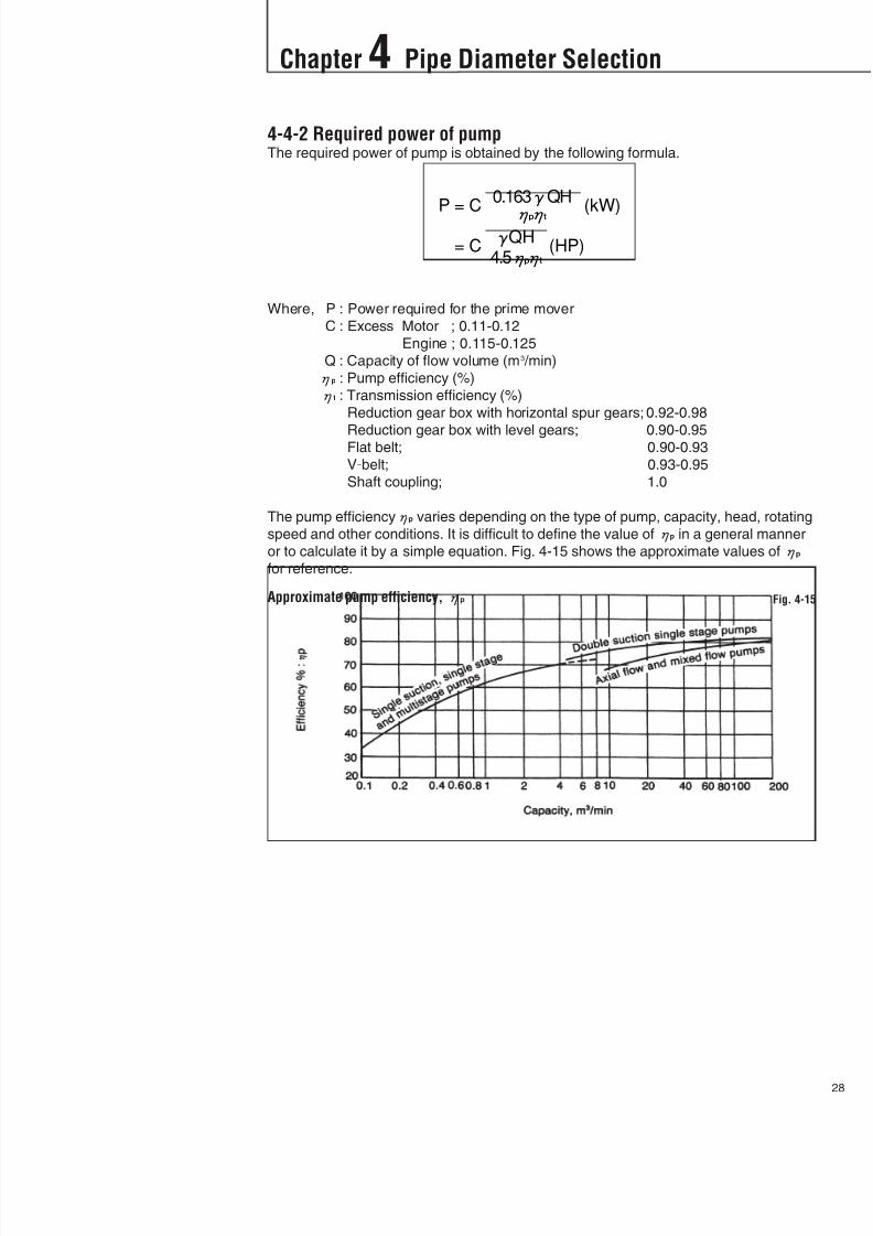
4-4-2 Required power of pumpThe required power of pump is obtained by the following formula.
Where, P : Power required for the prime mover
C : Excess Motor ; 0.11-0.12
Engine ; 0.115-0.125
Q : Capacity of flow volume (m3 /min)
p : Pump efficiency (%)
t : Transmission efficiency (%)
Reduction gear box with horizontal spur gears; 0.92-0.98
Reduction gear box with level gears; 0.90-0.95Flat belt; 0.90-0.93
V-belt; 0.93-0.95
Shaft coupling; 1.0
The pump efficiencyp varies depending on the type of pump, capacity, head, rotating
speed and other conditions. It is difficult to define the value ofp in a general manner
or to calculate it by a simple equation. Fig. 4-15 shows the approximate values ofp
for reference.
Approximate pump efficiency, p Fig. 4-15

8/11/2019 Design Manual ductile iron
http://slidepdf.com/reader/full/design-manual-ductile-iron 30/138
Chapter 4 Pipe Diameter Selection
9
4-5 Allowable FlowVelocity
4-6 Economical PipeDiameters
The recommended allowable flow velocity in ductile iron pipes, for design purpose, is
shown in Table 4-6 and no more than 5 m/s.
Water passing through the pipeline at a high velocity will abrade the lining. High flow
velocity will increase the head loss in the pipeline and requires larger pipe diameter or
higher pump head. It is recommended in many cases adopting a large pipe diameter
even though the initial cost is higher, because the difference of the material cost and
operation cost will be fully compensated by lower operation cost.
In case that water contains solid particles such as sand and soil to some extent, it is
necessary to adopt a lower flow velocity to prevent the abrasion of the lining, however
to prevent the sedimentation of them in the pipeline, the flow velocity should be notless than 0.3 m/s.
Determining the pipe diameter using hydraulic-flow formulas exclusively may not
result in the best size to use. The diameter of the pipe used should be the one which
results in the lowest capitalized cost. The capitalized cost is based on the costs of
initial material and equipment, pipe installation, operation, pumping, maintenance,
interest on the investment, and replacement. On extensive projects, it is customary to
design a number of alternative pipe diameters and select the most economical and
practical one.
4-6-1 Gravity pipelineIn a gravity pipeline, flow velocity should be increased as high as possible by making
the maximum possible use of head drop, but within the allowable flow velocity as
described in Sec. 4-5. This leads to the fact that minimum sized pipe will do the work
with the minimum construction cost. In other words, in a gravity pipeline, the size of
pipe will be determined by the given hydraulic conditions.
4-6-2 Pumping pipelineIn a pumping pipeline, combination of the size of pipe and head of pumps can be
numerous. If pipe size is small, although the pipe laying cost decreases, flow
resistance (pressure loss) will rise, hydraulic gradient will become acute, and it will be
essential to increase the pump head. Thus, not only the pumping equipment cost
becomes high but the power cost for pumping will be high after operation starts. Incontrast, if pipe size is large, even though laying cost will naturally increase, pumping
costs will be low.
In comparing the total expenses involved in the pumping system and those involved
in the pipe system only with operating expenses (interest in capital layout,
depreciation and maintenance costs), there can be only one, optimum economical
size of pipe.
Table 4-6Recommended flow velocity

8/11/2019 Design Manual ductile iron
http://slidepdf.com/reader/full/design-manual-ductile-iron 31/138
Chapter 4 Pipe Diameter Selection
30
4-7 Pipe Size forDistribution Network
It is desirable to design distribution pipes in a well-balanced network to provide
uniform pressure and uninterrupted service to the customers. For design of network
system, Hardy-Cross method is primarily used for manual calculation purpose. This
method is based on Hazen-Williams formula, and originates from the concept that the
water head loss at a certain point is proportional to the square of the flow volume, i.e.,
h = kQ2, where, k is coefficient. This calculation is to be made for each pipeline, with
the water head loss initiating in the counter-clockwise direction called positive (+) and
in the reverse direction, negative (-). When the pipeline is arranged in the form of
network,h = 0.
With this method, it is rare that the correct value is obtained from a single set of
calculations, and in many instances the original value, which is simply estimated, is
modified slightly and the relevant calculations are repeated over and over to bring it
closer to the correct value. The sequence of calculation is:
1. The overall pipeline network is divided into a number of sub-networks.
2. Provisionally set the flow volume Q and direction of the flow for each pipeline. In
normal instances, set the counter-clockwise direction as (+) and the reverse as (-).
3. Obtain h for Q of each pipeline. h and Q are the same sign.
4. Workout h/Q = hf Qn-1
for each pipeline, where hf is friction head.5. Workouth for each sub-network.
6. Obtainhf Qn-1 =h/Q for each sub-network and further calculate
nhf Qn-1 = nh/Q.
7. For each sub-network, calculate the modified valueQ of the flow volume.
8. Set each assumed flow volume Q, to whichQ is added, as the primary modified
flow volume of the sub-network.
9. Work out h for the primary modified flow volume and obtainh .
10. Ifh is not equal to 0, calculate the secondary modified flow volume according to
the same method as mentioned above. Then obtain h for it.
11. Then as these calculations are repeated h will begin to approach 0. Repeat these
calculations until h becomes close enough to 0 so that further calculations resultin no significant change in the value of h. Calculations can then stop at this stage.
Use the value of Q and h obtained in the last set of calculations as the final
values.

8/11/2019 Design Manual ductile iron
http://slidepdf.com/reader/full/design-manual-ductile-iron 32/138
Chapter 5 Water Hammer
1
5-1 General
5-2SimplifiedCalculation of WaterHammer
When the flow velocity of water in the pipeline is abruptly changed, a violent change
of water pressure occurs. This phenomenon is called “water hammer”. Water hammer
can take place either in gravity pipeline or pumping pipeline. Examples of transient
phenomena of water hammer are shown in Fig. 5-1 and 5-2.
Precautions must be taken not only against pressure increase (maximum pressure)
but also pressure decrease (minimum pressure).If the minimum pressure at any point along the pipeline goes below the saturated
vapor pressure of water, the pipeline will be exposed to a dangerous situation
because of the possibility of water column separation. This water column separation
should be avoided by using either surge tank, air chamber or other means. Pipeline
shall be designed so that expected minimum negative pressure in the pipeline by
water hammer is not lower than minus (–) 0.5 bar.
(1) Pressure wave velocity
Where, a : Pressure wave velocity (m/s)
: Unit weight of water (= 10 kN/m3)
K : Bulk modulus of compressibility of water (= 2106 kN/m2)
E : Modulus of elasticity of pipe material
(for ductile iron pipe, E = 1.7108 kN/m2)
D : Outside diameter of pipe (m)
t : Pipe wall thickness (m)
Examples of transient phenomenon of water hammer in gravity pipeline Fig. 5-1
Examples of transient phenomenon of water hammer in pumping pipeline Fig. 5-1
8/11/2019 Design Manual ductile iron
http://slidepdf.com/reader/full/design-manual-ductile-iron 33/138
Chapter 5 Water Hammer
32
If the diameter and wall thickness of the pipe are not uniform throughout the whole
length of the pipeline, calculate a1, a2,···an for the lengths L1, L2,···Ln of the parts of
pipeline whose diameter and wall thickness are identical. Then work out the average
value for the total length of the pipeline according to the following formula.
(2) Simplified calculation method of water hammer by rapid valve opening or closing
(in case of T<2L/a)
In this case, Joukowsky formula is used.
Where,H0 : Water head in the constant flowing condition (m)
V0 : Flow velocity in the constant flowing condition (m/s)
H : Water head at a given time after valve operation (m)V : Flow velocity at a given time after valve operation (m/s)
When valve is fully closed and V = 0, H - H0 = aV0 /g is the maximum additional
water head caused by water hammer.
(3) Simplified calculation method of water hammer by slow valve opening or closing
(in case of T>2L/a)
The approximation formula which is quite close to Allievi formula is based on the
assumption that from the time the first reflected wave returns to the valve until the
valve is fully closed, the pressure remains unchanged and that the effective
opening area of the valve is changed rectilinearly.
In this formula, (+) causes rise of the pressure at valve closing and (-) causes drop
at valve opening.
Where,L : Length of pipeline (m)
T : Time for valve closing or opening (sec)

8/11/2019 Design Manual ductile iron
http://slidepdf.com/reader/full/design-manual-ductile-iron 34/138
Chapter 5 Water Hammer
3
(4) Simplified calculation method of water hammer in pumped pipeline
In this case, there is direct or iterative calculation method based on differential
equations, diagrammatic calculations, etc., which involves a considerable amount
of tedious work. To obtain a rough idea, simplified Parmakian diagrams in Fig. 5-3
to 5-6 are handy and convenient.
Parmakian diagram for water hammer in pumping pipelines

8/11/2019 Design Manual ductile iron
http://slidepdf.com/reader/full/design-manual-ductile-iron 35/138
Chapter 5 Water Hammer
34
5-3 Prevention ofWater Hammer
Notes to Parmakian diagrams:Note 1.
Where, H0 : Normal head of pump (m)Q0 : Normal flow volume of pump (m3 /s)
GD2 /4g : Moment of inertia of the revolving parts (kgf-m·s2)
N0 : Normal revolution of pump (rpm)
L : Length of pipeline (m)
a : Velocity of pressure wave (m/s)
0 : Normal effective ratio of pump
2 : = aV0 /gH0 (when material and diameter of pipe are all identical)
= Q0(Ln /An)/gH0(Ln /an) (when they are different)
V0 : Normal flow velocity (m/s)
A : Sectional area of pipe (m2)
Note 2.
Moment of inertia of the revolving parts is mostly from GD2 of motor and the revolving parts of pump
contribute only about 10% of total. GD2 of motors varies depending on the type of motor and the
manufacturer.
The fundamental measure for water hammer prevention is to make the change of flow
velocity as slow as possible during the transitional period. Almost all devices for water
hammer prevention measure are designed for this purpose. Those devices can be
classified into the following three groups.
(1) to slow down the change of flow velocity
(2) to prevent the pressure drop
(3) to limit the pressure rise
Regarding the actual device for water hammer prevention, a simple device may be
adequate in some cases and complicated devices may be required in other cases.
Regardless, very careful investigation is required to make sure if it suits a particular
pipeline. Here, only basics for design are given in Table 5-1.
Water hammer prevention measure Table 5-1
8/11/2019 Design Manual ductile iron
http://slidepdf.com/reader/full/design-manual-ductile-iron 36/138
Chapter 6 Pipe Laying Conditions and External Loads
5
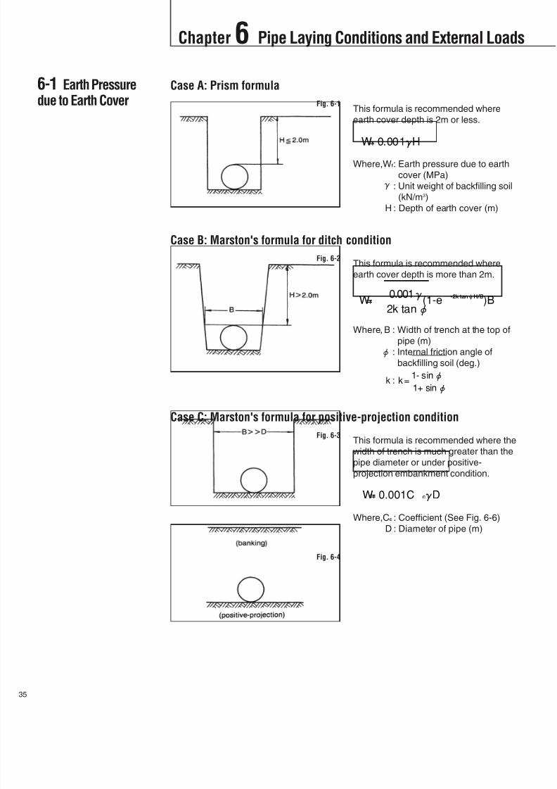
6-1 Earth Pressuredue to Earth Cover
Case A: Prism formula
This formula is recommended where
earth cover depth is 2m or less.
Where,Wf: Earth pressure due to earth
cover (MPa) : Unit weight of backfilling soil
(kN/m3)
H : Depth of earth cover (m)
Case B: Marston's formula for ditch condition
This formula is recommended where
earth cover depth is more than 2m.
Where, B : Width of trench at the top of
pipe (m)
: Internal friction angle of
backfilling soil (deg.)
k :
Case C: Marston's formula for positive-projection condition
This formula is recommended where the
width of trench is much greater than the
pipe diameter or under positive-
projection embankment condition.
Where,Cc : Coefficient (See Fig. 6-6)
D : Diameter of pipe (m)
Fig. 6-1
Fig. 6-2
Fig. 6-3
Fig. 6-4
8/11/2019 Design Manual ductile iron
http://slidepdf.com/reader/full/design-manual-ductile-iron 37/138
Chapter 6 Pipe Laying Conditions and External Loads
36
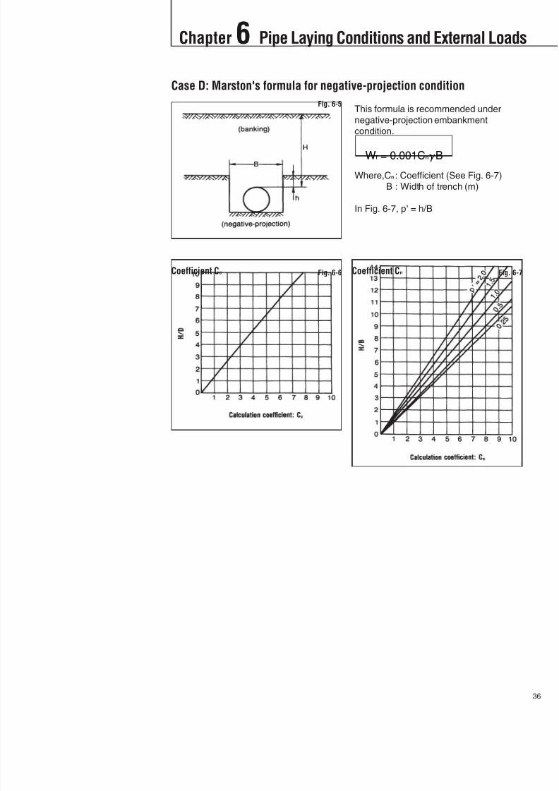
Case D: Marston's formula for negative-projection condition
This formula is recommended under
negative-projection embankment
condition.
Where,Cn : Coefficient (See Fig. 6-7)
B : Width of trench (m)
In Fig. 6-7, p = h/B
Fig. 6-5
Coefficient Cc Fig. 6-6 Coefficient Cn Fig. 6-7

8/11/2019 Design Manual ductile iron
http://slidepdf.com/reader/full/design-manual-ductile-iron 38/138
Chapter 6 Pipe Laying Conditions and External Loads
7
6-2 Earth Pressuredue to Vehicle Load
6-2-1 Truck loadEarth pressure due to truck load is calculated by Boussinesq formula.
Where, Wt : Earth pressure due to truck load (MPa)
F : Impact factor (= 1.5)
P : Load of one rear tire of truck (in case of 250 kN truck, P = 100 kN)
: Coefficient (See Fig. 6-8 and 6-9)
Coefficient for one truck Fig. 6-8
Coefficient for two trucks Fig. 6-9
8/11/2019 Design Manual ductile iron
http://slidepdf.com/reader/full/design-manual-ductile-iron 39/138
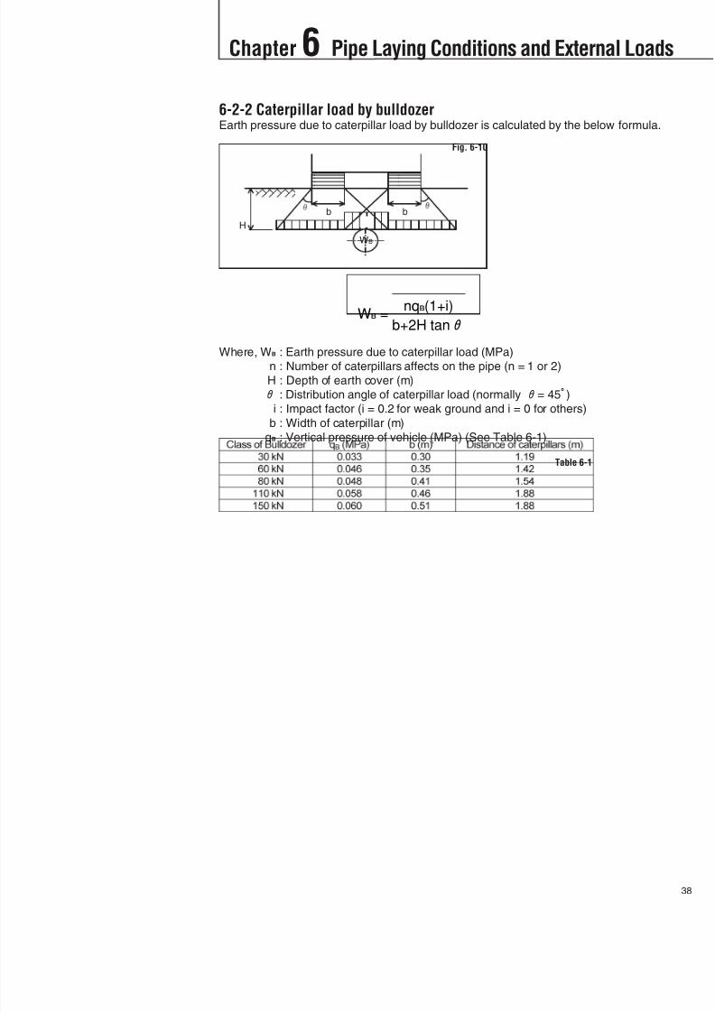
6-2-2 Caterpillar load by bulldozerEarth pressure due to caterpillar load by bulldozer is calculated by the below formula.
Where, WB : Earth pressure due to caterpillar load (MPa)n : Number of caterpillars affects on the pipe (n = 1 or 2)
H : Depth of earth cover (m)
: Distribution angle of caterpillar load (normally = 45)
i : Impact factor (i = 0.2 for weak ground and i = 0 for others)
b : Width of caterpillar (m)
qB : Vertical pressure of vehicle (MPa) (See Table 6-1)
Chapter 6 Pipe Laying Conditions and External Loads
38
Fig. 6-10
b b
WB
H
Table 6-1
8/11/2019 Design Manual ductile iron
http://slidepdf.com/reader/full/design-manual-ductile-iron 40/138
Chapter 7 Design of Ductile Iron Pipe
9
7-1 General
7-2 Design by ISO10803
Pipelines laid underground are subjected to many kinds of loads during in service,
and these loads should be taken into account in the stress analysis of the pipe. ISO
10803 and national standards are available for the design of ductile iron pipe.
In ISO 10803, the pipe wall thickness is designed to provide adequate strength
against the internal pressure and against the effects of external loads due to backfill
and traffic. The pipe wall thickness required for the internal pressure (t1) is checked by
hoop stress and that for external pressure (t2) by vertical deflection, and the nominal
wall thickness is the larger of t1 and t2 plus the manufacturing tolerance.
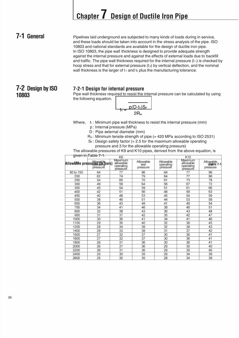
7-2-1 Design for internal pressurePipe wall thickness required to resist the internal pressure can be calculated by using
the following equation.
Where, t1 : Minimum pipe wall thickness to resist the internal pressure (mm)
p : Internal pressure (MPa)
D : Pipe external diameter (mm)
Rm : Minimum tensile strength of pipe (= 420 MPa according to ISO 2531)
SF : Design safety factor (= 2.5 for the maximum allowable operating
pressure and 3 for the allowable operating pressure)
The allowable pressures of K9 and K10 pipes, derived from the above equation, is
given in Table 7-1.
Allowable pressures (in bars) Table 7-1
8/11/2019 Design Manual ductile iron
http://slidepdf.com/reader/full/design-manual-ductile-iron 41/138
Chapter 7 Design of Ductile Iron Pipe
40
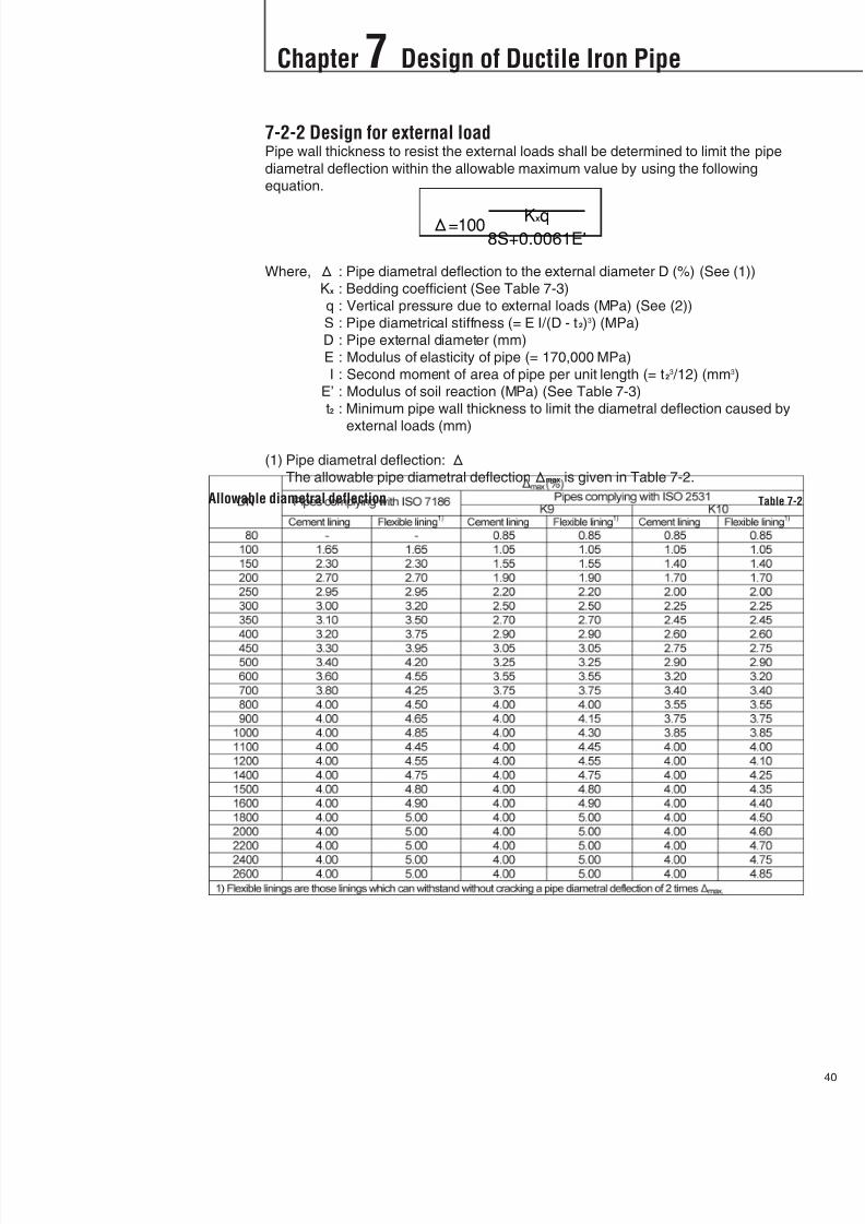
7-2-2 Design for external loadPipe wall thickness to resist the external loads shall be determined to limit the pipe
diametral deflection within the allowable maximum value by using the following
equation.
Where, : Pipe diametral deflection to the external diameter D (%) (See (1))
Kx : Bedding coefficient (See Table 7-3)
q : Vertical pressure due to external loads (MPa) (See (2))
S : Pipe diametrical stiffness (= E I/(D - t2)3) (MPa)
D : Pipe external diameter (mm)
E : Modulus of elasticity of pipe (= 170,000 MPa)
I : Second moment of area of pipe per unit length (= t23 /12) (mm3)
E’ : Modulus of soil reaction (MPa) (See Table 7-3)
t2 : Minimum pipe wall thickness to limit the diametral deflection caused by
external loads (mm)
(1) Pipe diametral deflection: The allowable pipe diametral deflectionmax is given in Table 7-2.
Allowable diametral deflection Table 7-2
8/11/2019 Design Manual ductile iron
http://slidepdf.com/reader/full/design-manual-ductile-iron 42/138
Chapter 7 Design of Ductile Iron Pipe
1
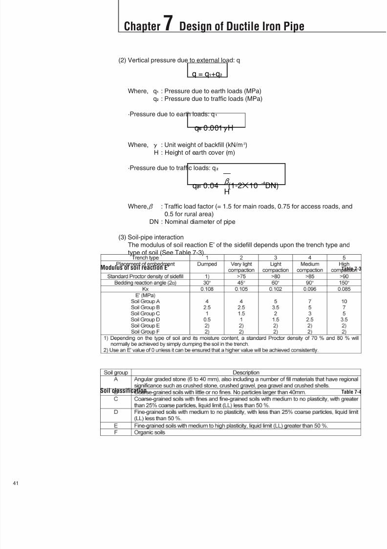
(2) Vertical pressure due to external load: q
Where, q1 : Pressure due to earth loads (MPa)
q2 : Pressure due to traffic loads (MPa)
·Pressure due to earth loads: q1
Where, : Unit weight of backfill (kN/m3)
H : Height of earth cover (m)
·Pressure due to traffic loads: q2
Where, : Traffic load factor (= 1.5 for main roads, 0.75 for access roads, and
0.5 for rural area)
DN : Nominal diameter of pipe
(3) Soil-pipe interaction
The modulus of soil reaction E’ of the sidefill depends upon the trench type and
type of soil (See Table 7-3).
Modulus of soil reaction E' Table 7-3
Soil classification Table 7-4

8/11/2019 Design Manual ductile iron
http://slidepdf.com/reader/full/design-manual-ductile-iron 43/138
Chapter 7 Design of Ductile Iron Pipe
42
7-2-3 Determination of pipe wall thicknessThe minimum pipe wall thickness t is the larger of t1 and t2.
The required nominal pipe wall thickness is determined by adding the tolerance
specified in ISO 2531 (i.e. 1.3 + 0.001DN mm) to the minimum pipe wall thickness t,
the appropriate standard pipe wall thickness class can thus be selected.
7-2-4 Allowable earth cover depthAn example of the allowable depth of earth cover extracted from ISO 10803 is shown
in Table 7-5.Note, for other conditions, see ISO 10803.
Allowable depth of earth cover for K9 pipes under main road (= 1.5) Table 7-5
8/11/2019 Design Manual ductile iron
http://slidepdf.com/reader/full/design-manual-ductile-iron 44/138
Chapter 7 Design of Ductile Iron Pipe
3
7-3 Kubota's DesignMethod
Kubota Corporation has different design method which is based on Japan Water
Works Association Standard. In this method, tensile stress due to the internal
pressure and bending stress due to the external loads are checked and the sum of
them shall be less than the minimum tensile strength of ductile iron pipe.
Furthermore, vertical deflection of pipe is also checked.
7-3-1 Design for internal pressureTensile stress due to internal pressure can be calculated by using the equation of
hoop stress.
Where, t : Tensile stress due to internal pressure (MPa)
P : Internal pressure (MPa)
DN : Nominal pipe diameter (mm)t : Net pipe wall thickness (mm)
In accordance with ISO 2531, t = T – (1.3 + 0.001DN)
T : Nominal pipe wall thickness (mm)
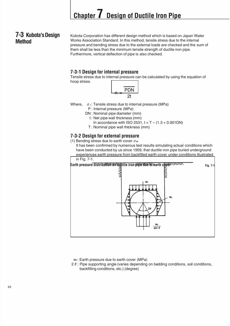
7-3-2 Design for external pressure(1) Bending stress due to earth coverbf
It has been confirmed by numerous test results simulating actual conditions which
have been conducted by us since 1959, that ductile iron pipe buried underground
experiences earth pressure from backfilled earth cover under conditions illustrated
in Fig. 7-1.
wf : Earth pressure due to earth cover (MPa)
2: Pipe supporting angle (varies depending on bedding conditions, soil conditions,
backfilling conditions, etc.) (degree)
Earth pressure distribution on ductile iron pipe due to earth cover Fig. 7-1

8/11/2019 Design Manual ductile iron
http://slidepdf.com/reader/full/design-manual-ductile-iron 45/138
Chapter 7 Design of Ductile Iron Pipe
44
Assuming earth pressure distribution as Fig. 7-1, bending moment on pipe wall Mt
can be calculated by the following equation.
Where, kf : Coefficient of moment due to earth cover
For design purpose, the following pipe supporting angles can be assumed depending
on backfilling conditions.
For normal soil condition only. Pipes laid on a hard trench bottom will be supported with a smaller angle.
On the other hand, pipes laid on a soft trench bottom will be supported with a larger angle.
Accordingly, bending stress on the pipe wall due to earth cover can be calculated by
the following equation.
Where, Z : Modulus of section per unit length (= t2 /6) (m2)
The calculation of the stress should be made at both the crown and the bottom ofpipe.
Coefficient kf Table 7-6
Pipe supporting angle Table 7-7

8/11/2019 Design Manual ductile iron
http://slidepdf.com/reader/full/design-manual-ductile-iron 46/138
Chapter 7 Design of Ductile Iron Pipe
5
7-3-3 Bending stress due to truck loadbt
Earth pressure distribution on ductile iron pipe due to truck load can be assumed as
shown in Fig. 7-2.
wt : Earth pressure due to truck load (MPa)
Bending moment and bending stress on the pipe wall due to truck load Mt can be
calculated by the following equations.
Where, kt : Coefficient of moment due to truck load
kt = 0.076 at pipe crown and 0.011 at pipe bottom
Earth pressure distribution on ductile iron pipe due to truck load Fig. 7-2
8/11/2019 Design Manual ductile iron
http://slidepdf.com/reader/full/design-manual-ductile-iron 47/138
Chapter 7 Design of Ductile Iron Pipe
46
7-4 Example of StressAnalysis by KubotaMethod
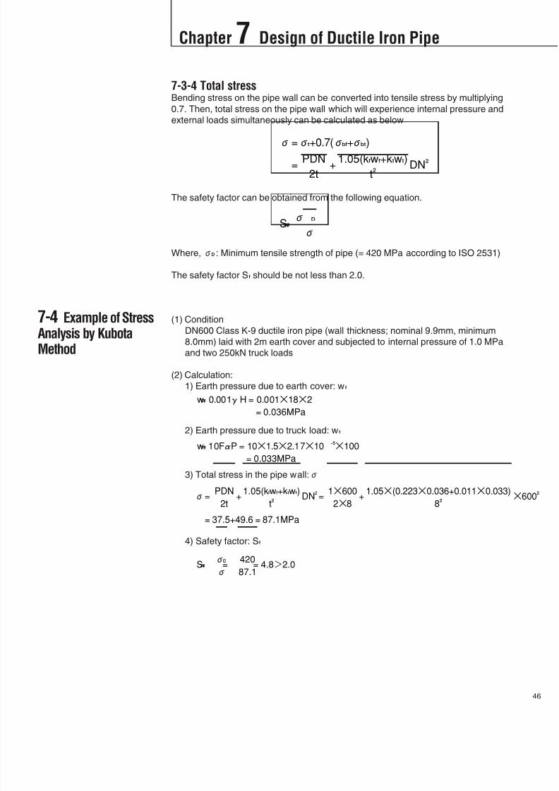
7-3-4 Total stressBending stress on the pipe wall can be converted into tensile stress by multiplying
0.7. Then, total stress on the pipe wall which will experience internal pressure and
external loads simultaneously can be calculated as below
The safety factor can be obtained from the following equation.
Where,D : Minimum tensile strength of pipe (= 420 MPa according to ISO 2531)
The safety factor Sf should be not less than 2.0.
(1) Condition
DN600 Class K-9 ductile iron pipe (wall thickness; nominal 9.9mm, minimum
8.0mm) laid with 2m earth cover and subjected to internal pressure of 1.0 MPa
and two 250kN truck loads
(2) Calculation:
1) Earth pressure due to earth cover: wf
2) Earth pressure due to truck load: wt
3) Total stress in the pipe wall:
4) Safety factor: Sf

8/11/2019 Design Manual ductile iron
http://slidepdf.com/reader/full/design-manual-ductile-iron 48/138
Chapter 7 Design of Ductile Iron Pipe
7
7-5 DiametralDeflection
7-5-1 Diametral deflection due to earth load:f
Where, k : Coefficient of deformation
7-5-2 Deformation due to truck load:t
7-5-3 Total deformations:
The total deformation should be not more than 3% of the nominal diameter of pipe.
Coefficient k Table 7-8

8/11/2019 Design Manual ductile iron
http://slidepdf.com/reader/full/design-manual-ductile-iron 49/138
8/11/2019 Design Manual ductile iron
http://slidepdf.com/reader/full/design-manual-ductile-iron 50/138
Chapter 8 Thrust Anchoring
9
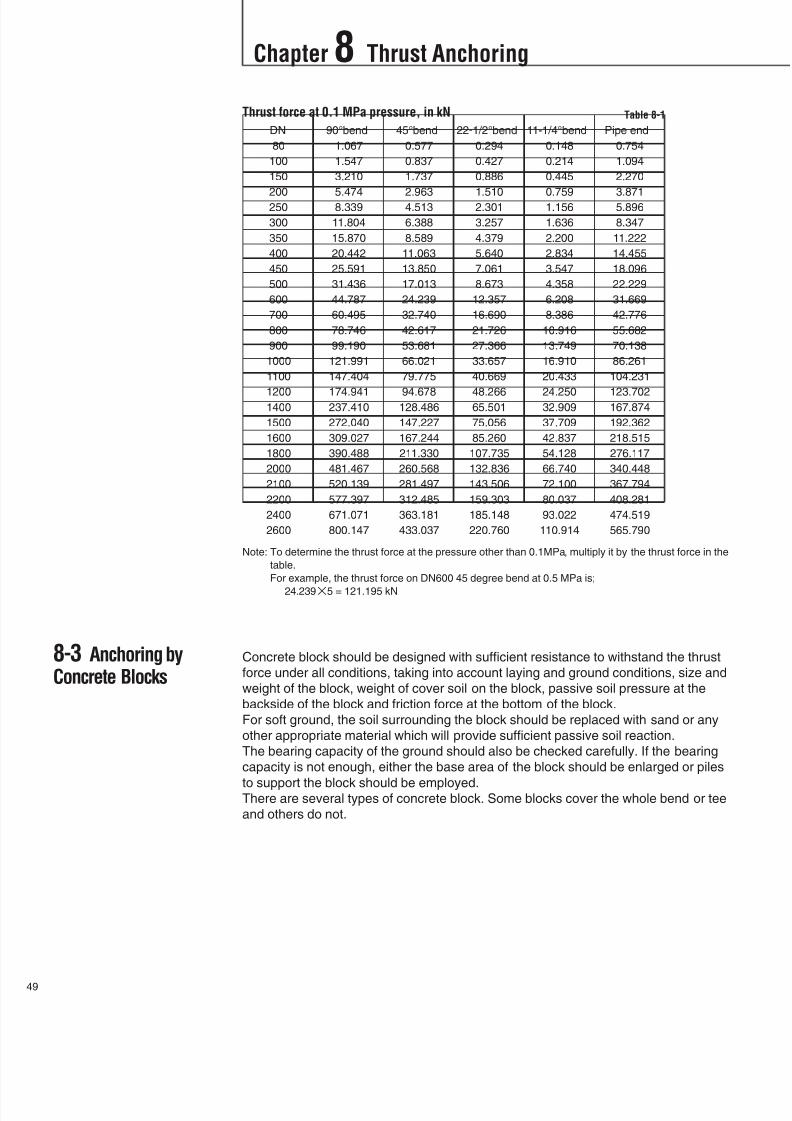
8-3 Anchoring byConcrete Blocks
Note: To determine the thrust force at the pressure other than 0.1MPa, multiply it by the thrust force in the
table.
For example, the thrust force on DN600 45 degree bend at 0.5 MPa is;
24.2395 = 121.195 kN
Concrete block should be designed with sufficient resistance to withstand the thrust
force under all conditions, taking into account laying and ground conditions, size and
weight of the block, weight of cover soil on the block, passive soil pressure at the
backside of the block and friction force at the bottom of the block.
For soft ground, the soil surrounding the block should be replaced with sand or any
other appropriate material which will provide sufficient passive soil reaction.
The bearing capacity of the ground should also be checked carefully. If the bearing
capacity is not enough, either the base area of the block should be enlarged or piles
to support the block should be employed.There are several types of concrete block. Some blocks cover the whole bend or tee
and others do not.
Thrust force at 0.1 MPa pressure, in kN Table 8-1
DN 90°bend 45°bend 22-1/2°bend 11-1/4°bend Pipe end
80 1.067 0.577 0.294 0.148 0.754
100 1.547 0.837 0.427 0.214 1.094
150 3.210 1.737 0.886 0.445 2.270
200 5.474 2.963 1.510 0.759 3.871250 8.339 4.513 2.301 1.156 5.896
300 11.804 6.388 3.257 1.636 8.347
350 15.870 8.589 4.379 2.200 11.222
400 20.442 11.063 5.640 2.834 14.455
450 25.591 13.850 7.061 3.547 18.096
500 31.436 17.013 8.673 4.358 22.229
600 44.787 24.239 12.357 6.208 31.669
700 60.495 32.740 16.690 8.386 42.776
800 78.746 42.617 21.726 10.916 55.682
900 99.190 53.681 27.366 13.749 70.138
1000 121.991 66.021 33.657 16.910 86.261
1100 147.404 79.775 40.669 20.433 104.231
1200 174.941 94.678 48.266 24.250 123.7021400 237.410 128.486 65.501 32.909 167.874
1500 272.040 147.227 75.056 37.709 192.362
1600 309.027 167.244 85.260 42.837 218.515
1800 390.488 211.330 107.735 54.128 276.117
2000 481.467 260.568 132.836 66.740 340.448
2100 520.139 281.497 143.506 72.100 367.794
2200 577.397 312.485 159.303 80.037 408.281
2400 671.071 363.181 185.148 93.022 474.519
2600 800.147 433.037 220.760 110.914 565.790
8/11/2019 Design Manual ductile iron
http://slidepdf.com/reader/full/design-manual-ductile-iron 51/138
Chapter 8 Thrust Anchoring
50
8-4 Design ofConcrete Block
(Fittings encased)
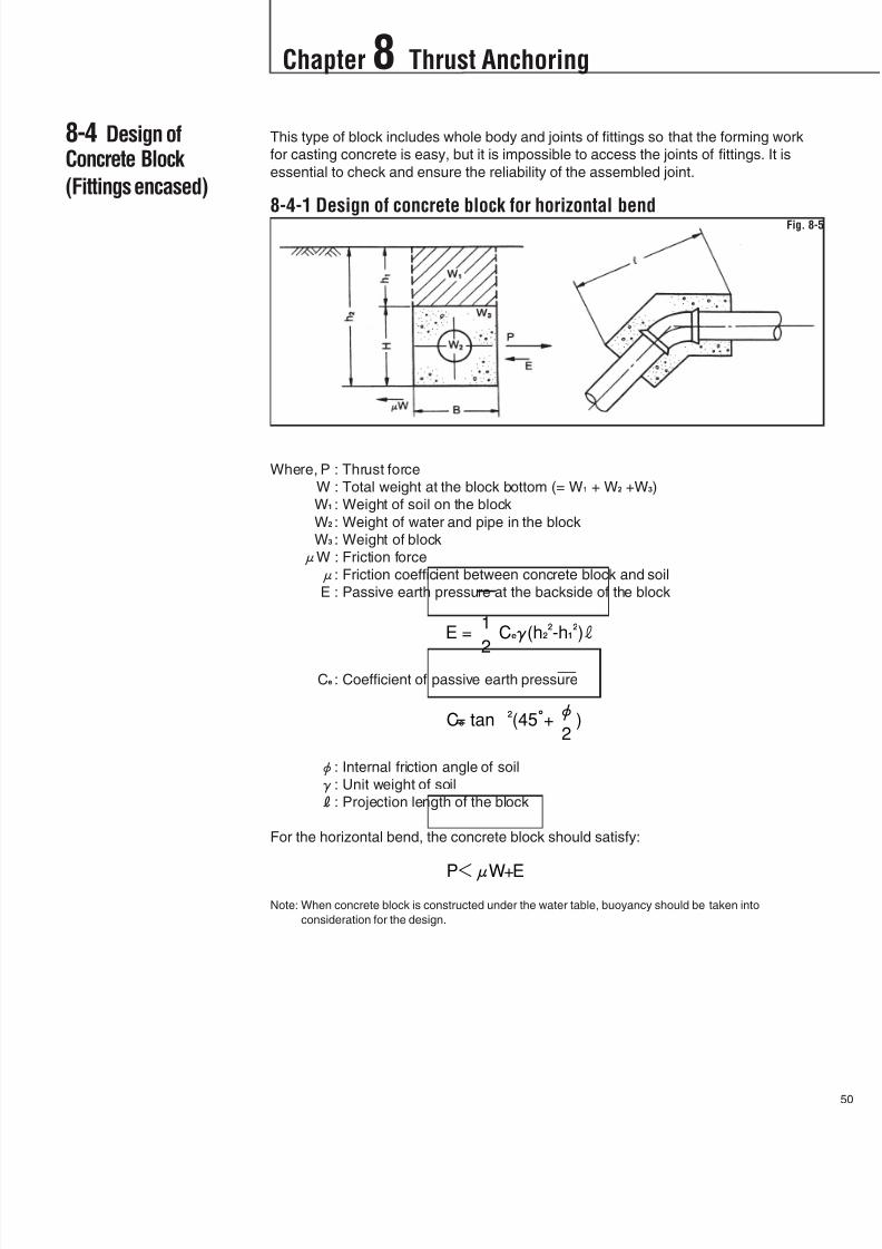
This type of block includes whole body and joints of fittings so that the forming work
for casting concrete is easy, but it is impossible to access the joints of fittings. It is
essential to check and ensure the reliability of the assembled joint.
8-4-1 Design of concrete block for horizontal bend
Where, P : Thrust force
W : Total weight at the block bottom (= W1 + W2 +W3)
W1 : Weight of soil on the block
W2 : Weight of water and pipe in the block
W3 : Weight of block
W : Friction force
: Friction coefficient between concrete block and soil
E : Passive earth pressure at the backside of the block
Ce : Coefficient of passive earth pressure
: Internal friction angle of soil
: Unit weight of soil
R: Projection length of the block
For the horizontal bend, the concrete block should satisfy:
Note: When concrete block is constructed under the water table, buoyancy should be taken into
consideration for the design.
Fig. 8-5
R

8/11/2019 Design Manual ductile iron
http://slidepdf.com/reader/full/design-manual-ductile-iron 52/138
Chapter 8 Thrust Anchoring
1
8-4-2 Example of design(1) Design conditions
Bend: DN60045Pipe outside diameter; D = 635 mm (pipe wall thickness T = 9.9 mm)
Maximum internal pressure; p = 1.0 MPa (=1000 kN/m2)
Depth of earth cover; h1 = 1.2 m
Unit weight of soil;s = 16 kN/m3
Unit weight of concrete;c = 23 kN/m3
Internal friction angle of soil;= 30Friction coefficient;= 0.5
(2) Thrust force: P
P = 2pAsin( /2) = 21000 /40.6352sin(45/2)= 242.39 kN
(3) Design of block
1) Weight of soil on the block: W1
W1 =s h1 2L B = 161.021.31.3 = 54.08 kN
2) Weight of water and pipe in the block: W2
W2 =w A2L+d(D-T)T2 L
= 10 /40.6221.3 + 70.5(0.635 – 0.0099)0.009921.3
= 10.91 kN
3) Weight of block: W3
W3 =c[BH – ( /4)D2]2L = 23[1.31.3 - /40.6352]21.3 = 82.12 kN
4) Total weight: W
W = W1 + W2 +W3 = 54.08 + 10.91 + 82.12 = 147.11 kN
5) Friction force: F
F =W = 0.5147.11 = 73.56 kN
6) Passive earth pressure at the backside of the block: EE = 1/2 Ces(h2
2 – h12)R = 1/2tan2(45+ 30/2)16(2.32 – 1.02)2.9
= 298.58 kN
7) Total resistance force: R
R = F + E = 73.56 + 298.58 = 372.14 kN
8) Safety factor: Sf
Sf = R/P = 372.14/242.39 = 1.54
The calculated safety factor is larger than 1.5, therefore this block will be
satisfactory.
9) Required bearing capacity of the ground: Sb
Sb = W/2LB = 147.11/(21.31.3) = 43.5 kN/m2
When the bearing capacity of the ground is larger than the calculated figures, the
block will be satisfactory; but if not, the bottom of the block should be enlarged.
Fig. 8-6

8/11/2019 Design Manual ductile iron
http://slidepdf.com/reader/full/design-manual-ductile-iron 53/138
Chapter 8 Thrust Anchoring
52
8-4-3 Design of concrete block for upward vertical bend
Where, P : Thrust force
P1 : Horizontal component of the thrust force
P2 : Vertical component of the thrust force(W – P2) : Friction force
E : Passive earth pressure at the backside of the block
F : Active earth pressure at the both sides of the block
Concrete block shall be designed to satisfy the following conditions.
Against the horizontal component of the thrust force
Against the vertical component of the thrust force
Where, B :Width of the block
R: Length of the block
Ce’: Coefficient of active earth pressure
Note: When concrete block is constructed under the water table, buoyancy should be taken into
consideration for the design.
Fig. 8-7
R
8/11/2019 Design Manual ductile iron
http://slidepdf.com/reader/full/design-manual-ductile-iron 54/138
Chapter 8 Thrust Anchoring
3
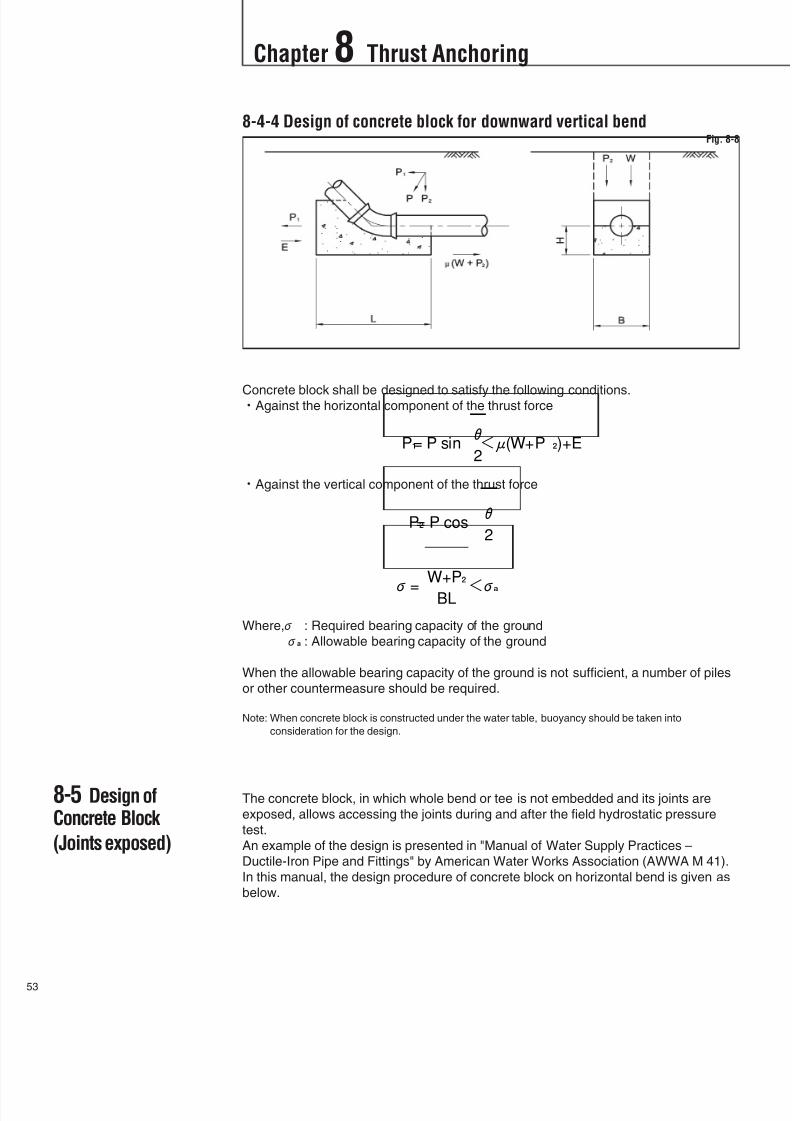
8-5 Design ofConcrete Block
(Joints exposed)
8-4-4 Design of concrete block for downward vertical bend
Concrete block shall be designed to satisfy the following conditions.Against the horizontal component of the thrust force
Against the vertical component of the thrust force
Where, : Required bearing capacity of the ground
a : Allowable bearing capacity of the ground
When the allowable bearing capacity of the ground is not sufficient, a number of piles
or other countermeasure should be required.
Note: When concrete block is constructed under the water table, buoyancy should be taken into
consideration for the design.
The concrete block, in which whole bend or tee is not embedded and its joints are
exposed, allows accessing the joints during and after the field hydrostatic pressure
test.
An example of the design is presented in "Manual of Water Supply Practices –
Ductile-Iron Pipe and Fittings" by American Water Works Association (AWWA M 41).
In this manual, the design procedure of concrete block on horizontal bend is given as
below.
Fig. 8-8

8/11/2019 Design Manual ductile iron
http://slidepdf.com/reader/full/design-manual-ductile-iron 55/138
Resistance is provided by transferring the thrust force to the soil through the larger
bearing area of the block such that the resultant pressure against soil does not
exceed the bearing strength of the soil. Design of thrust blocks consists of
determining the appropriate bearing area of the block for a particular set of conditions.The followings are general criteria for bearing block design.
- Bearing surface should, where possible, be placed against undisturbed soil. Where
it is not possible, the fill between the bearing surface and undisturbed soil must be
compacted to at least 90 percent Standard Proctor density.
- Block height h should be equal to or less than one-half the total depth to the bottom
of the block H T , but not less than the pipe outside diameter D .
- Block height h , should be chosen such that the calculated block width b varies
between one and two times the height.
The required block bearing area Ab is:
Where, P : Thrust force
Sf : Safety factor (usually 1.5)
Sb : Horizontal bearing strength of soil
Then, for horizontal bend,
Chapter 8 Thrust Anchoring
54
8-6 Reference Tables
Fig. 8-9
Friction coefficient between pipe or concrete and soil Table 8-2
8/11/2019 Design Manual ductile iron
http://slidepdf.com/reader/full/design-manual-ductile-iron 56/138
Chapter 8 Thrust Anchoring
5
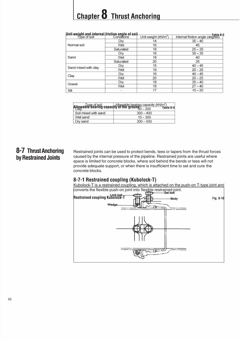
8-7 Thrust Anchoringby Restrained Joints
Restrained joints can be used to protect bends, tees or tapers from the thrust forces
caused by the internal pressure of the pipeline. Restrained joints are useful where
space is limited for concrete blocks, where soil behind the bends or tees will not
provide adequate support, or when there is insufficient time to set and cure the
concrete blocks.
8-7-1 Restrained coupling (Kubolock-T)Kubolock-T is a restrained coupling, which is attached on the push-on T-type joint and
converts the flexible push-on joint into flexible restrained joint.
Unit weight and internal friction angle of soil Table 8-3
Allowable bearing capacity of the ground Table 8-4
Restrained coupling Kubolock-T Fig. 8-10

8/11/2019 Design Manual ductile iron
http://slidepdf.com/reader/full/design-manual-ductile-iron 57/138
Chapter 8 Thrust Anchoring
56
Kubolock-T is applicable to pipes and fittings with our T-type push-on joint ranging
from DN80 to DN600.Note. Kubolock-T of DN 700 to DN1200 may be available upon request.
The allowable hydraulic pressure and deflection angle of Kubolock-T are shown in the
below table.
8-7-2 Retainer gland (Kubolock-K)Kubolock-K is a retainer gland which converts the flexible mechanical K-type joint into
flexible restrained joint.
Kubolock-K is applicable to pipes and fittings with our K-type mechanical joint ranging
from DN80 to DN600.
The allowable hydraulic pressure and deflection angle of Kubolock-K are shown in thebelow table.
Table 8-5
Retainer gland Kubolock-K Fig. 8-11
Table 8-6

8/11/2019 Design Manual ductile iron
http://slidepdf.com/reader/full/design-manual-ductile-iron 58/138
Chapter 8 Thrust Anchoring
7
8-8 RestrainedLength
8-7-3 TF-type restrained jointTF-type joint is rigid type restrained push-on joint ranging from DN400 to DN1600.
Lock ring is placed in the grooves provided on the socket and spigot. TF-type joint isof moment-bearing type and the deflection angle is zero for the design purpose. The
sealing portion of TF-type joint is the same as that of push-on T-type joint.
The allowable bending moment and hydraulic pressure of TF-type joint are shown in
the below table.
8-8-1 Required restrained length for Kubolock (-T and -K)The required restrained length of the pipes at each side of horizontal bend is so
decided that the friction force and passive earth pressure on the restrained pipes are
larger than the thrust force caused by the internal pressure. As these restrained jointsare non-moment-bearing type so that the passive earth pressure is expected on only
the first pipe adjacent to the each side of bend.
TF-type restrained joint Fig. 8-12
Table 8-7
8/11/2019 Design Manual ductile iron
http://slidepdf.com/reader/full/design-manual-ductile-iron 59/138
Chapter 8 Thrust Anchoring
58
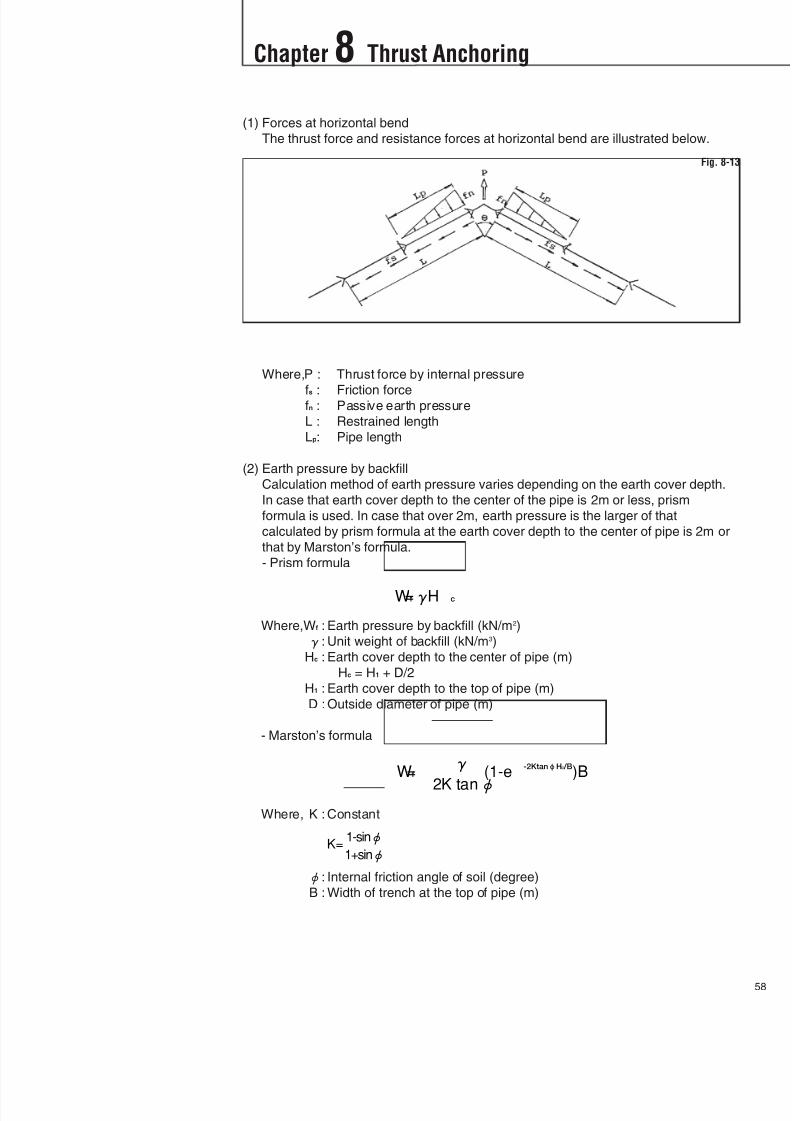
(1) Forces at horizontal bend
The thrust force and resistance forces at horizontal bend are illustrated below.
Where,P : Thrust force by internal pressure
fs : Friction forcefn : Passive earth pressure
L : Restrained length
Lp: Pipe length
(2) Earth pressure by backfill
Calculation method of earth pressure varies depending on the earth cover depth.
In case that earth cover depth to the center of the pipe is 2m or less, prism
formula is used. In case that over 2m, earth pressure is the larger of that
calculated by prism formula at the earth cover depth to the center of pipe is 2m or
that by Marston’s formula.
- Prism formula
Where,Wf : Earth pressure by backfill (kN/m2)
: Unit weight of backfill (kN/m3)
Hc : Earth cover depth to the center of pipe (m)
Hc = H1 + D/2
H1 : Earth cover depth to the top of pipe (m)
D : Outside diameter of pipe (m)
- Marston’s formula
Where, K : Constant
: Internal friction angle of soil (degree)
B : Width of trench at the top of pipe (m)
Fig. 8-13
8/11/2019 Design Manual ductile iron
http://slidepdf.com/reader/full/design-manual-ductile-iron 60/138
Chapter 8 Thrust Anchoring
9
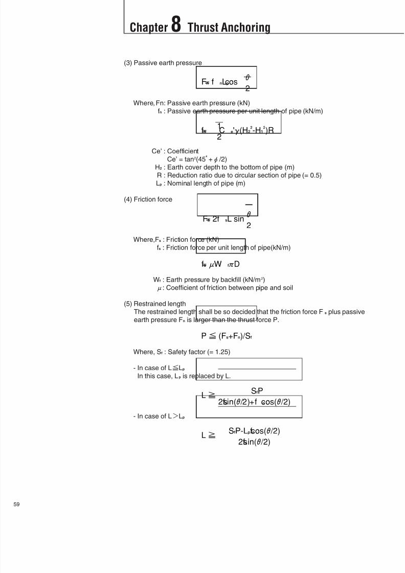
(3) Passive earth pressure
Where,Fn: Passive earth pressure (kN)
fn : Passive earth pressure per unit length of pipe (kN/m)
Ce’ : Coefficient
Ce’ = tan2(45+ /2)
H2 : Earth cover depth to the bottom of pipe (m)
R : Reduction ratio due to circular section of pipe (= 0.5)
Lp : Nominal length of pipe (m)
(4) Friction force
Where,Fs : Friction force (kN)
fs : Friction force per unit length of pipe(kN/m)
Wf : Earth pressure by backfill (kN/m2)
: Coefficient of friction between pipe and soil
(5) Restrained lengthThe restrained length shall be so decided that the friction force Fs plus passive
earth pressure Fn is larger than the thrust force P.
Where, Sf : Safety factor (= 1.25)
- In case of LLp
In this case, Lp is replaced by L.
- In case of LLp

8/11/2019 Design Manual ductile iron
http://slidepdf.com/reader/full/design-manual-ductile-iron 61/138
Chapter 8 Thrust Anchoring
60
The required restrained lengths on each side of bend for Kubolock at 1.0 MPa are
tabulated in Table 8-9.
Calculation conditions;
- Internal pressure: 1.0 MPa- Earth cover depth: 1.2 m
- Unit weight of soil: 16 kN/m3
- Internal friction angle of backfill soil: 30- Friction coefficient: 0.3
- Pipe length: 4 m (DN80), 6 m (DN100)
8-8-2 Required restrained length for TF-type jointAs resistance forces, friction force between the pipes and the surrounding soil and
passive earth pressure at the backside of the whole restrained pipes are considered.
The required restrained length for moment-bearing restrained joint shall be calculated
so that the resistance force comes to be not less than the thrust force and also the
bending moment applied to the restrained joints does not exceed the allowable value
of the joint.
The required restrained length of pipes L1 for the resistance forces is given by the
below equation.
Where, Sf : Safety factor (= 1.25)
At the same time, the required restrained length of pipes L2 for the bending moment is
given by the below equation.
Table 8-9Required restrained lengths for Kubolock at 1.0 MPa
Fig. 8-14

8/11/2019 Design Manual ductile iron
http://slidepdf.com/reader/full/design-manual-ductile-iron 62/138
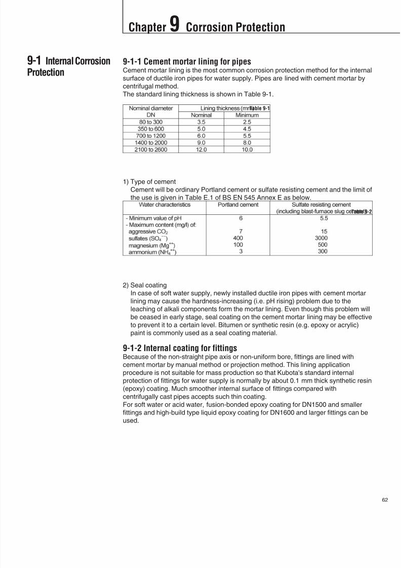
8/11/2019 Design Manual ductile iron
http://slidepdf.com/reader/full/design-manual-ductile-iron 63/138
9-1-1 Cement mortar lining for pipesCement mortar lining is the most common corrosion protection method for the internal
surface of ductile iron pipes for water supply. Pipes are lined with cement mortar by
centrifugal method.
The standard lining thickness is shown in Table 9-1.
1) Type of cement
Cement will be ordinary Portland cement or sulfate resisting cement and the limit of
the use is given in Table E.1 of BS EN 545 Annex E as below.
2) Seal coating
In case of soft water supply, newly installed ductile iron pipes with cement mortar
lining may cause the hardness-increasing (i.e. pH rising) problem due to theleaching of alkali components form the mortar lining. Even though this problem will
be ceased in early stage, seal coating on the cement mortar lining may be effective
to prevent it to a certain level. Bitumen or synthetic resin (e.g. epoxy or acrylic)
paint is commonly used as a seal coating material.
9-1-2 Internal coating for fittingsBecause of the non-straight pipe axis or non-uniform bore, fittings are lined with
cement mortar by manual method or projection method. This lining application
procedure is not suitable for mass production so that Kubota's standard internal
protection of fittings for water supply is normally by about 0.1 mm thick synthetic resin
(epoxy) coating. Much smoother internal surface of fittings compared with
centrifugally cast pipes accepts such thin coating.For soft water or acid water, fusion-bonded epoxy coating for DN1500 and smaller
fittings and high-build type liquid epoxy coating for DN1600 and larger fittings can be
used.
Table 9-1
Table 9-2
Chapter 9 Corrosion Protection
62
9-1 Internal CorrosionProtection

8/11/2019 Design Manual ductile iron
http://slidepdf.com/reader/full/design-manual-ductile-iron 64/138
3
Chapter 9 Corrosion Protection
9-2 ExternalCorrosion Protection
9-1-3 Aggressive fluidsWhen aggressive fluid for cement mortar lining will be transported through the pipe,
special care shall be taken. Aggressive fluid for cement mortar lining will be:
1) Acid water (see Table 9-2)
2) Soft water (i.e. water with low contents of calcium and magnesium salts)
As an evaluation method of the aggressiveness of water to cement mortar lining,
Langelier Saturation Index will be commonly used (see Appendix A).
3) Sewage
When temperature is high (e.g. more than 20), flow velocity is extremely low
(e.g. below 0.3 m/s) and flow does not fill the pipe, sulfides in the anaerobic
sewage will be reduced to hydrogen sulfide (H2S) and finally to sulfuric acid
(H2SO4) by bacteria which will damage the pipes and other facilities. These
phenomena are observed on not only gravity sewer line but also pumping main at
summit portions in the pipeline and at the discharge portions to the tank.
9-1-4 Special LiningFor aggressive fluid, special lining or other measures should be applied.
1) Epoxy coatingEpoxy paint is of high-build 2-part liquid type and the thickness of the coating will
be 300 or 500 microns depending on the type of aggressive fluid.
2) Fusion-bonded epoxy coating
Fusion-bonded epoxy coating has excellent acid and chemical resistances and
adhesion to the pipe. Fusion-bonded epoxy coating material is of solid powder and
fuses and forms smooth and thick coating film when applied to the pre-heated pipe.
Fusion-bonded epoxy coating will have a thickness of 300 or 500 microns
depending on the type of aggressive fluid.
Fusion-bonded epoxy coating contains no solvent therefore does less affect the
quality of water in the pipeline.
3) Polyurethane coating
Polyurethane coating material is of 2-part solvent free type and the standard
thickness of the coating will be 1.0 to 1.5 mm.
9-2-1 Standard coatingIt is well known that cast iron pipe is highly resistant to corrosion and consequently,
cast iron pipes have a long service life. This is evidenced throughout the world by
many instances of cast iron pipes having been in continuous use for more than 100
years without the need of repair or replacement. Ductile iron has the same chemical
composition as cast iron and so possesses the same corrosion resistance.
Generally the external surface of ductile iron pipe and fittings is coated with at least
70 micron thick synthetic resin or bituminous paint. Nowadays zinc coating beneath
the standard coating in accordance with ISO 8179 is commonly used. The zinc
coating for pipe is metallic zinc spray and that for fittings is zinc rich paint and theapplication of zinc coating is not less than 130 g/m2 in case of metallic zinc spray and
150 g/m2 in case of zinc rich paint.
9-2-2 Protection in aggressive soilWhen pipeline route is designed, it is recommended investigating the aggressiveness
of the soil in which pipes to be laid.
Generally following soils will be considered aggressive for ductile iron pipes:
acid soil containing industrial wastes
soils near the sea or soils containing high content of salts
peaty, silty or marshy soil
reclaimed land in industrial area
ground where corrosion of existing steel/cast iron pipes was reported

8/11/2019 Design Manual ductile iron
http://slidepdf.com/reader/full/design-manual-ductile-iron 65/138
64
Chapter 9 Corrosion Protection
BS EN 545 Annex D gives the limits of the application of the standard coatings as
below:
soils with a low resistivity, less than 1500-cm above the water table or less than
2500-cm below the water table
soils with a pH below 6
soils with contamination by certain waters or organic or industrial effluents
in the occurrence of stray currents or corrosion cells due to external metallic
structures
As an evaluation method of aggressiveness of soil, American standard
ANSI/AWWA C105/ A21.5 may be adopted (See Appendix B).
9-2-3 Polyethylene sleeving methodUnder normal conditions, standard coating will provide pipes and fittings sufficient
protection to corrosion. However, when pipes and fittings are laid in corrosive soil
areas, polyethylene sleeve corrosion protection method in addition to the standard
coating is recommended. In this method the entire length of pipe is encased with 0.2
mm-thick polyethylene sleeves in the trench after pipes are jointed. Polyethylene
sleeve prevents the direct contact between the pipe and aggressive soil.Polyethylene sleeve is the most common corrosion prevention method for ductile iron
pipe to the corrosive soil and is specified in ISO standard (ISO 8180) and national
standards.
9-2-4 Special coatingEven though polyethylene sleeves will provide the pipes effective corrosion protection
in corrosive soil, some ground conditions will limit the corrosion protection of ductile
iron pipe by polyethylene sleeves. They are:
Resistivity of the soil is less than 1000 -cm and ground water fluctuates at the
pipe
Ground is rocky and ground water flows along the pipeline
In such case, special coating should be recommended.
1) Polyethylene coatingPolyethylene coating is applied by continuous wrapping of the melted polyethylene
sheet extruded from extruder. The standard thickness of the polyethylene coating
is 2 to 3 mm varying depends on the pipe size. Spigot end is however free of
polyethylene and is coated with epoxy paint to not hinder the assembling of the
joints. After pipes are jointed, the jointed portion is normally protected with heat-
shrinkable sleeve or plastic tape wrapping. Polyethylene coating can be applied to
pipes only.
2) Polyurethane coating
Polyurethane coating is applied by spray method. The standard thickness of
polyurethane coating is 0.7 to 1 mm. Spigot end is however free of polyurethane
coating and is coated with epoxy paint.
3) Tape wrappingPipe is wrapped spirally with PVC or polyethylene corrosion protective tape. Tape
wrapping is normally applied to pipes on site.
9-2-5 Coating for exposed pipingFor the aboveground piping, zinc primer with finish coating conforming to ISO 8179-1
or 8179-2 is recommended.
However, pipelines installed inside or immediately outside of water treatment facilities
and pumping stations may be coated with paints in distinguished color. In such case,
coating system shown in Table 9-3 is recommended.
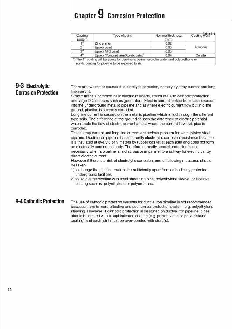
8/11/2019 Design Manual ductile iron
http://slidepdf.com/reader/full/design-manual-ductile-iron 66/138
5
Chapter 9 Corrosion Protection
9-3 ElectrolyticCorrosion Protection
9-4 Cathodic Protection
There are two major causes of electrolytic corrosion, namely by stray current and long
line current.
Stray current is common near electric railroads, structures with cathodic protection
and large D.C sources such as generators. Electric current leaked from such sources
into the underground metallic pipeline and at where electric current flow out into the
ground, pipeline is severely corroded.
Long line current is caused on the metallic pipeline which is laid through the differenttype soils. The difference of the ground causes the difference of electric potential
which leads the flow of electric current and at where the current flow out, pipe is
corroded.
These stray current and long line current are serious problem for weld-jointed steel
pipeline. Ductile iron pipeline has inherently electrolytic corrosion resistance because
it is insulated at every 6 or 9 meters by rubber gasket at each joint and does not form
an electrically continuous body. Therefore normally special protection is not
necessary when a pipeline is laid across or in parallel to a railway for electric car by
direct electric current.
However if there is a risk of electrolytic corrosion, one of following measures should
be taken.
1) to change the pipeline route to be sufficiently apart from cathodically protected
underground facilities2) to isolate the pipeline with steel sheathing pipe, polyethylene sleeve, or isolative
coating such as polyethylene or polyurethane.
The use of cathodic protection systems for ductile iron pipeline is not recommended
because there is more effective and economical protection system, e.g. polyethylene
sleeving. However, if cathodic protection is designed on ductile iron pipeline, pipes
should be coated with a sophisticated coating (e.g. polyethylene or polyurethane
coating) and each joint must be over-bonded with strap(s).
Table 9-3
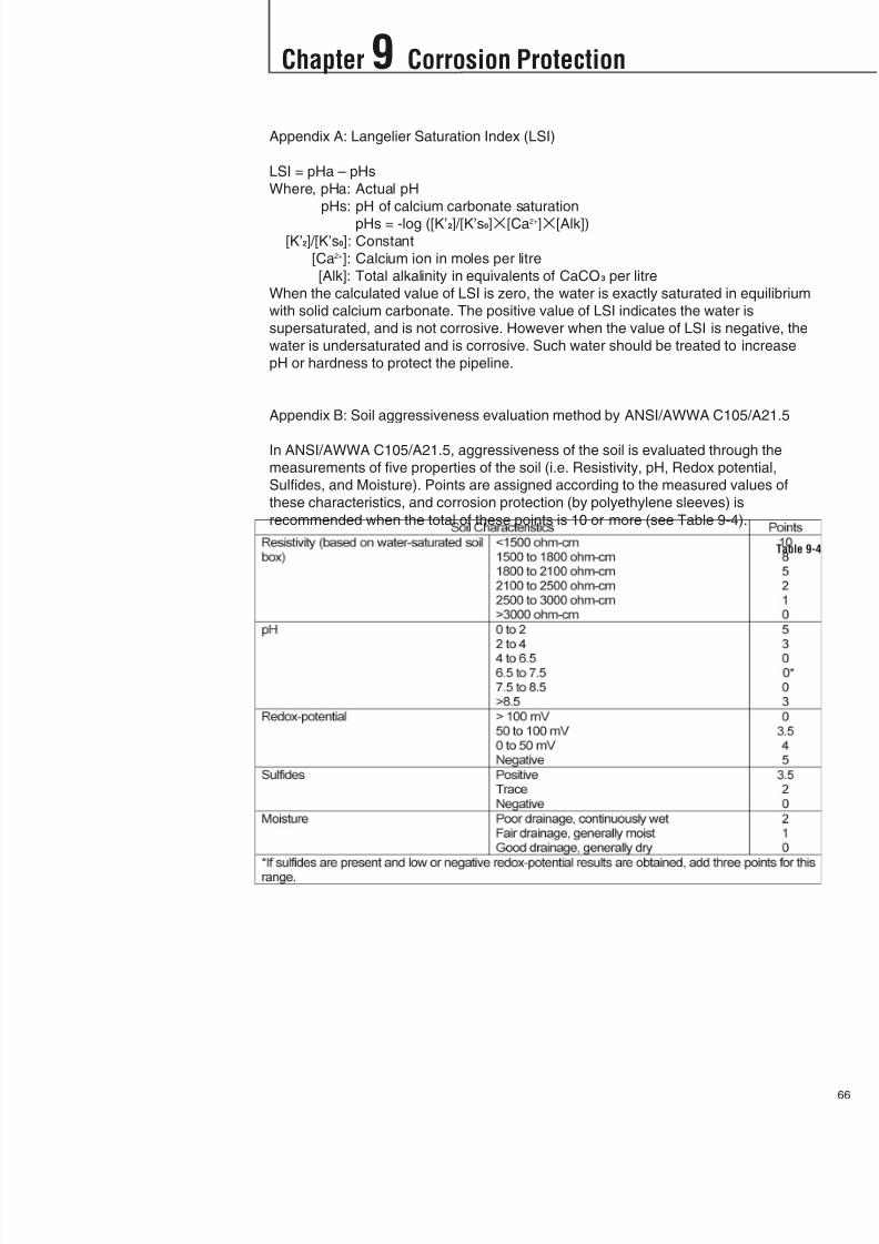
8/11/2019 Design Manual ductile iron
http://slidepdf.com/reader/full/design-manual-ductile-iron 67/138
Appendix A: Langelier Saturation Index (LSI)
LSI = pHa – pHs
Where, pHa: Actual pH
pHs: pH of calcium carbonate saturation
pHs = -log ([K’2]/[K’s0][Ca2+][Alk])
[K’2]/[K’s0]: Constant
[Ca2+]: Calcium ion in moles per litre
[Alk]: Total alkalinity in equivalents of CaCO3 per litre
When the calculated value of LSI is zero, the water is exactly saturated in equilibrium
with solid calcium carbonate. The positive value of LSI indicates the water is
supersaturated, and is not corrosive. However when the value of LSI is negative, the
water is undersaturated and is corrosive. Such water should be treated to increase
pH or hardness to protect the pipeline.
Appendix B: Soil aggressiveness evaluation method by ANSI/AWWA C105/A21.5
In ANSI/AWWA C105/A21.5, aggressiveness of the soil is evaluated through the
measurements of five properties of the soil (i.e. Resistivity, pH, Redox potential,
Sulfides, and Moisture). Points are assigned according to the measured values of
these characteristics, and corrosion protection (by polyethylene sleeves) is
recommended when the total of these points is 10 or more (see Table 9-4).
66
Chapter 9 Corrosion Protection
Table 9-4

8/11/2019 Design Manual ductile iron
http://slidepdf.com/reader/full/design-manual-ductile-iron 68/138
7
10-1 DrawingProcedure of PipingDiagrams
Chapter 10 Pipeline Drawings
Fig. 10-1 shows the procedure for drawing the piping diagrams with examples.
Flow chart for drawing procedure of piping diagrams Fig. 10-1
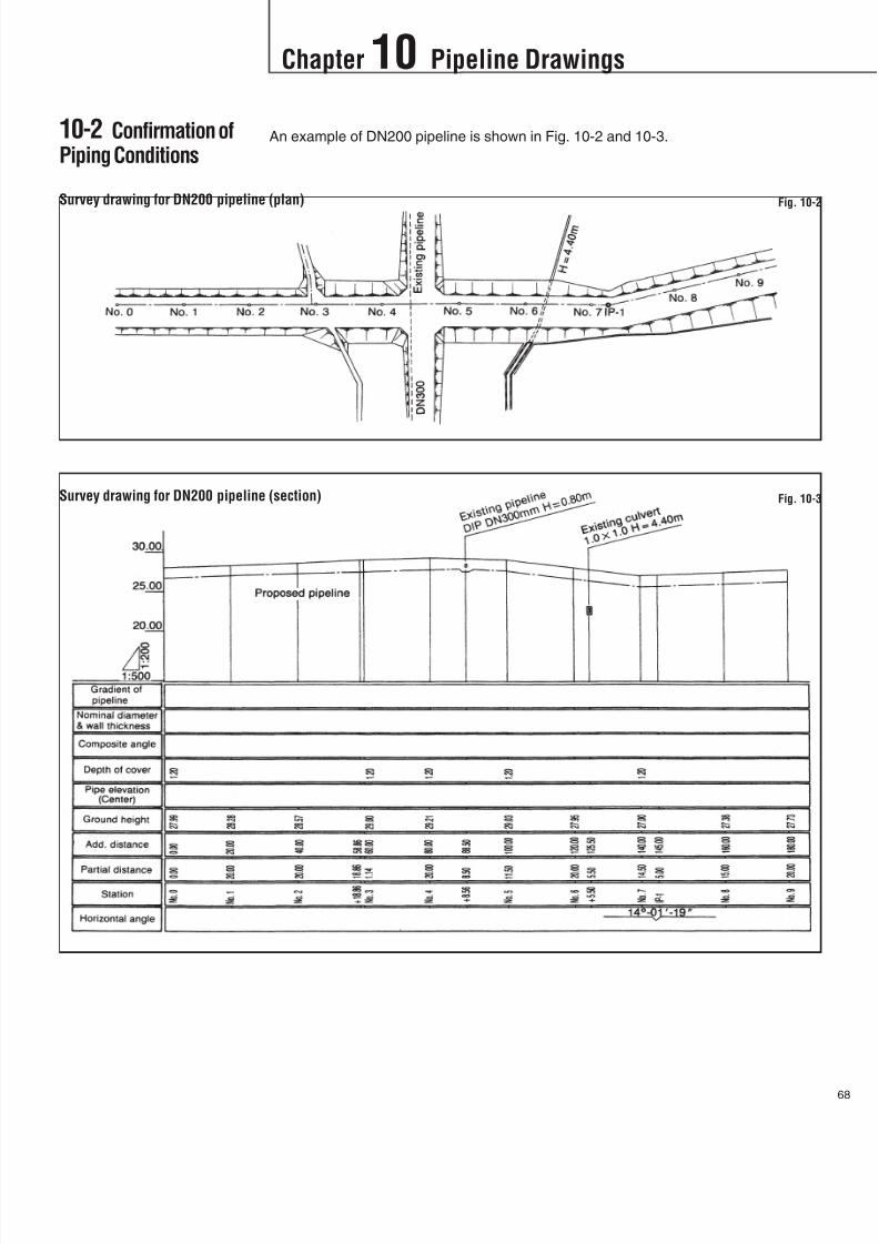
8/11/2019 Design Manual ductile iron
http://slidepdf.com/reader/full/design-manual-ductile-iron 69/138
An example of DN200 pipeline is shown in Fig. 10-2 and 10-3.
68
Survey drawing for DN200 pipeline (plan) Fig. 10-2
Survey drawing for DN200 pipeline (section) Fig. 10-3
Chapter 10 Pipeline Drawings
10-2 Confirmation ofPiping Conditions
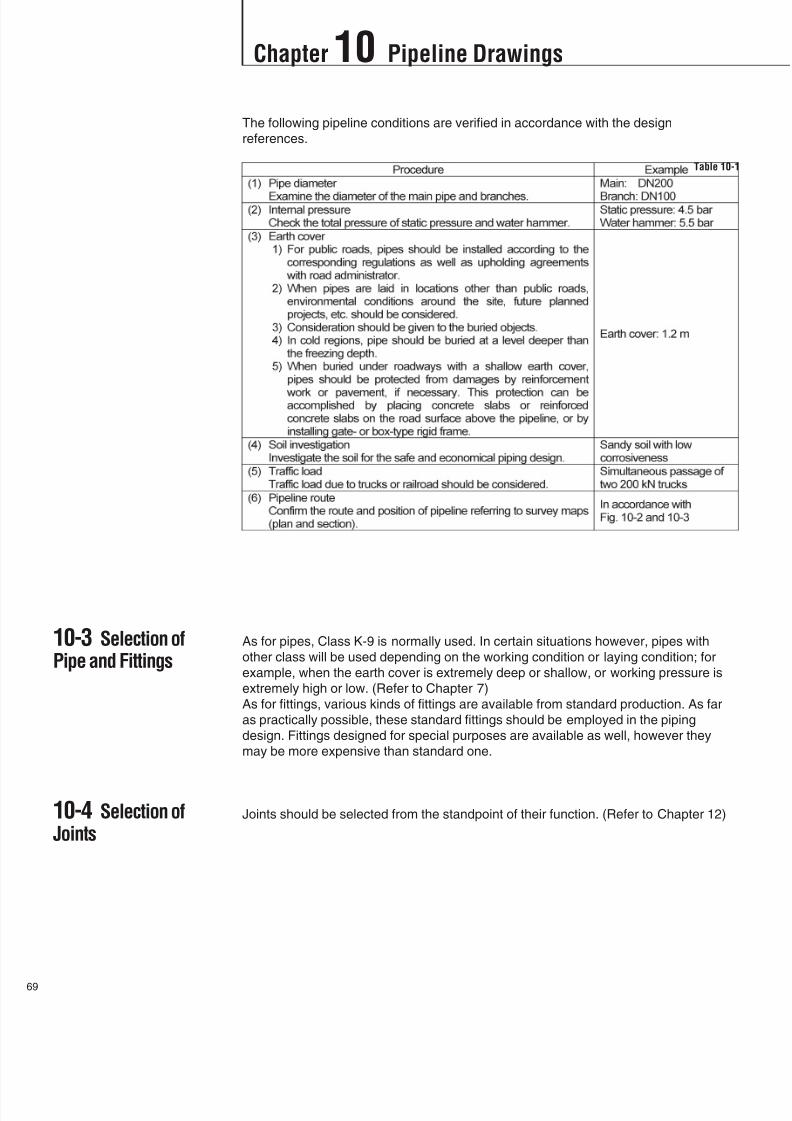
8/11/2019 Design Manual ductile iron
http://slidepdf.com/reader/full/design-manual-ductile-iron 70/138

8/11/2019 Design Manual ductile iron
http://slidepdf.com/reader/full/design-manual-ductile-iron 71/138
An example of piping composition determination is shown in Table-10-2.
70
Table 10-2
Chapter 10 Pipeline Drawings
10-5 Determinationof Piping Composition

8/11/2019 Design Manual ductile iron
http://slidepdf.com/reader/full/design-manual-ductile-iron 72/138

8/11/2019 Design Manual ductile iron
http://slidepdf.com/reader/full/design-manual-ductile-iron 73/138
72
Calculation sheet for pipe arrangement (Table 10-7) is necessary to decide on the
use of bends.
Table 10-3
Chapter 10 Pipeline Drawings
10-6 Determinationof Bends

8/11/2019 Design Manual ductile iron
http://slidepdf.com/reader/full/design-manual-ductile-iron 74/138
3
Chapter 10 Pipeline Drawings
Table 10-3

8/11/2019 Design Manual ductile iron
http://slidepdf.com/reader/full/design-manual-ductile-iron 75/138
Table 10-3
74
Chapter 10 Pipeline Drawings
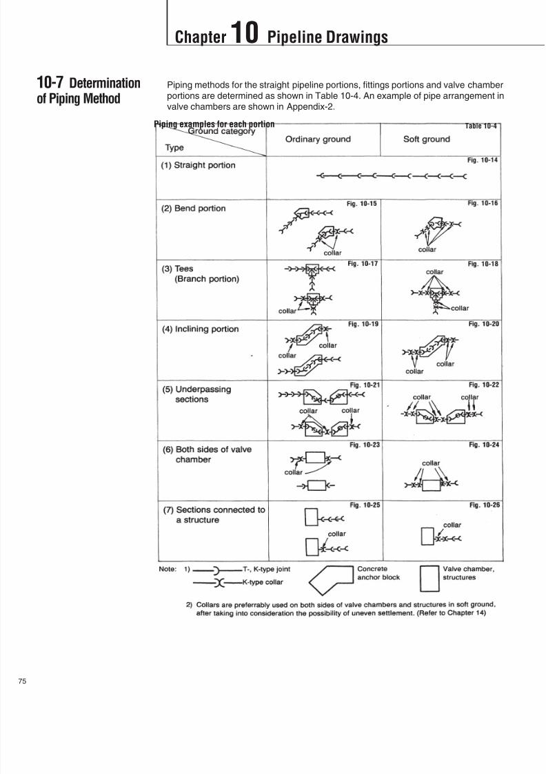
8/11/2019 Design Manual ductile iron
http://slidepdf.com/reader/full/design-manual-ductile-iron 76/138

8/11/2019 Design Manual ductile iron
http://slidepdf.com/reader/full/design-manual-ductile-iron 77/138
Fittings such as bends and tees are affected horizontally or vertically by thrust forces
caused by internal pressure of the pipeline. Consequently, fittings may move and
joints be separated. Such fittings must be anchored against the thrust forces. For
anchoring, various methods may be employed, including concrete block and
restrained joints. A combination of the concrete block and restrained joints can be
applied. (Refer to Chapter 8)
76
Table 10-5
Chapter 10 Pipeline Drawings
10-8 Anchoring ofFittings
10-9 Calculation ofPipe Cut Length
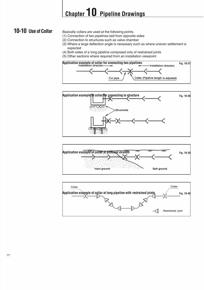
8/11/2019 Design Manual ductile iron
http://slidepdf.com/reader/full/design-manual-ductile-iron 78/138
7
Chapter 10 Pipeline Drawings
10-10 Use of Collar Basically collars are used at the following points.
(1) Connection of two pipelines laid from opposite sides
(2) Connection to structures such as valve chamber
(3) Where a large deflection angle is necessary such as where uneven settlement is
expected
(4) Both sides of a long pipeline composed only of restrained joints
(5) Other sections where required from an installation viewpoint
Application example of collar for connecting two pipelines Fig. 10-37
Application example of collar for connecting to structure Fig. 10-38
Application example of collar at different stratum Fig. 10-39
Application example of collar at long pipeline with restrained joints Fig. 10-40
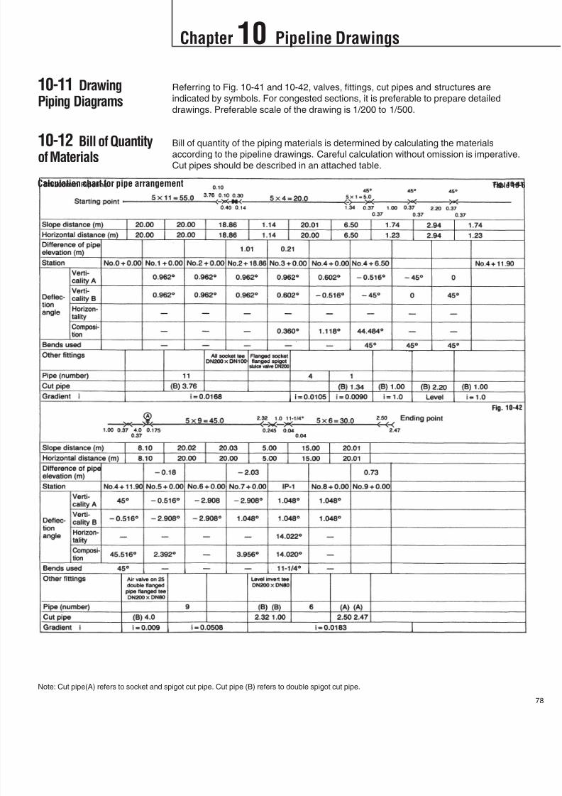
8/11/2019 Design Manual ductile iron
http://slidepdf.com/reader/full/design-manual-ductile-iron 79/138
78
Note: Cut pipe(A) refers to socket and spigot cut pipe. Cut pipe (B) refers to double spigot cut pipe.
Chapter 10 Pipeline Drawings
10-11 DrawingPiping Diagrams
10-12 Bill of Quantityof Materials
Referring to Fig. 10-41 and 10-42, valves, fittings, cut pipes and structures are
indicated by symbols. For congested sections, it is preferable to prepare detailed
drawings. Preferable scale of the drawing is 1/200 to 1/500.
Bill of quantity of the piping materials is determined by calculating the materials
according to the pipeline drawings. Careful calculation without omission is imperative.
Cut pipes should be described in an attached table.
Calculation chart for pipe arrangement Table 10-6

8/11/2019 Design Manual ductile iron
http://slidepdf.com/reader/full/design-manual-ductile-iron 80/138
9
Chapter 10 Pipeline Drawings
DN200 pipeline (plan) Fig. 10-43

8/11/2019 Design Manual ductile iron
http://slidepdf.com/reader/full/design-manual-ductile-iron 81/138
80
DN200 pipeline (section) Fig. 10-44
Chapter 10 Pipeline Drawings

8/11/2019 Design Manual ductile iron
http://slidepdf.com/reader/full/design-manual-ductile-iron 82/138
1
Chapter 11 Installation
11-1General
11-2Unloading fromTruck
This chapter offers recommendations for appropriate trench conditions for ductile iron
pipelines.
Pipes shall be unloaded by lifting with crane or forklift. When crane is used pipes shall
be lifted with wire ropes or nylon slings. In this case ensure the pipes are correctly
balanced. Pipes should not be lifted with a single wire rope. Use of hooks covered
with rubber sheets or cloths are recommended to prevent the damage of the external
coating and internal lining of the pipe. Each fitting shall be lifted with wire rope or
nylon sling passed through it. In this case coverage should be provided to the wire
rope or nylon sling at each end of the fittings to prevent rapid abrasion.
Fig. 11-1
Fig. 11-2

8/11/2019 Design Manual ductile iron
http://slidepdf.com/reader/full/design-manual-ductile-iron 83/138
82
11-3 Storage
11-4 Trenching
Pipes shall be stocked on the level ground. Timbers, having enough height to prevent
direct contact of the pipe with the ground, shall be placed so that each end of pipe
protrudes about one meter from the timbers. The number of the timbers will be 3 for 4
or 5 m long pipe, 4 for 6 m long pipe and 6 for 9 m long pipe. Pipes shall be secured
with chocks before releasing wire ropes otherwise pipes may fall off.
Pipes should be stacked on timbers within the recommended tiers in Table 11-1.
11-4-1 Width of trenchThe width of trench should be ample enough to permit pipe to be laid and jointed
properly. The recommendable trench width for ductile iron pipe will be typicallynominal diameter of pipe plus 600 mm (e.g. 1200 mm in case of DN600) and more at
the top of the pipe.
However, trench width shall be decided depending on the ground condition. In case of
soft ground, trench shall be widened or sheeting shall be provided to prevent the
collapse of the trench wall. When rocks are encountered during excavation, all rocks
have to be removed to provide a clearance of at least 150 mm below and on each
side of pipe for DN600 and smaller, and 250 mm for DN700 and larger.
Extra width should be provided to permit placement of timber supports, sheeting,
bracing and appurtenance when they are employed.
In case that pipeline is deflected at the joint the trench shall be widened appropriate
for the amount of deflection.
11-4-2 Depth of trenchWhen pipe will be laid under a public road, the depth of trench should be
accomplished in accordance with national or local regulations.
The depth of the pipeline should be decided in order to protect the pipe from damage
caused by earth pressure and traffic loads. Under a public road with traffic loads,
nominal covering depth between the top of the pipe and ground surface should be 1.2
m under traffic road or 1.0 m under non-traffic road and in any case not less than 0.6
m unless otherwise specified. If it is impossible to make the covering depth more than
0.6 m, pipe should be protected by paving the road surface above the pipe with
concrete slabs or surrounding with rigid box type or gate type concrete frame.
When pipe is laid under sidewalk or road where no vehicular traffic is permitted
reduced covering depth will be allowed. However where water table is high and
Recommended stacking tiers Table 11-1
Chapter 11 Installation

8/11/2019 Design Manual ductile iron
http://slidepdf.com/reader/full/design-manual-ductile-iron 84/138
3
Chapter 11 Installation
11-5 PreviousExcavation
11-6 Drainage ofTrench
11-7 Pipe Laying
threatens to float the pipe, pipe should be laid with enough covering depth to prevent
floating.
When pipe is laid across or close to other underground facilities, a distance of at least
0.3 m should be maintained.
11-4-3 Bell holesHoles for pipe sockets should be provided at each joint, but should be no larger than
necessary for joint assembly and for assurance that pipe barrels will lay flat on the
trench bottom.
11-4-4 Condition of trench bottomTrench bottom should be true and even in order to provide support for full length of
the pipe barrel. Generally pipes can be laid on the flat trench bottom directly without
special bedding in normal ground condition. However bedding by sand or selected
material should be provided especially when the ground is rocky or soft.
For soft ground, sand will be spread in the trench bottom to a depth of at least 300
mm or half of the nominal diameter of pipe whichever is larger. In case that ground is
extremely soft and is unstable, adoption of piling, chemical injection to solidification,sand-drain method should be recommended.
The bottom of trench shall be consolidated and leveled.
If the trench passes over a sewer or other previous excavation, the trench bottom
should be confirmed to other specified standards by Authorities and sufficiently
compacted to provide support equal to that of the native soil.
Prior to pipe laying, any water remaining in the trench such as storm water or
underground water should be removed with a sump pump. In this case, the pumpshould be placed in small pit provided to collect the water. If necessary, well point
should be employed.
For jointing and convenient work performance, proper implements, tools and facilities
should be provided. All pipes, fittings, valves and hydrants are laid along the trench
on the opposite side from the excavated earth.
11-7-1 Lowering of pipesAll pipes should be carefully lowered into the trench by using crane, ropes or other
suitable tools or equipment in such a manner as to prevent the body, coating andlining of water main materials. Under no circumstances shall water main materials be
dropped or dumped into the trench.
Ductile iron pipes and fittings should be lifted or lowered by using wire rope or nylon
sling. When using wire rope, cushion pads or rubber sleeves must be used as a cover
to protect the outside coating of pipes and fittings. (See Fig. 11-1 and 11-2)
11-7-2 Examination of materialsAll pipes and fittings should be carefully inspected for damage and other defects
before installation.

8/11/2019 Design Manual ductile iron
http://slidepdf.com/reader/full/design-manual-ductile-iron 85/138
84
11-8 ValveInstallation
11-9 Backfilling
11-7-3 Pipe endsAll lumps, blisters and excessive coating should be removed from the outside of
spigot end and inside of socket at where rubber gasket will be set. These portions
should be wiped clean and dry, and be free from dirt, sand, grit or any foreign
materials before pipes and fittings are laid.
11-7-4 Pipe cleanlinessForeign material should be prevented from entering the pipe and fittings while they
are placed in the trench.
11-7-5 Pipe placementAs each pipe is placed in the trench, joint is assembled and pipe brought to correct
line and grade. Pipe should be so placed that the manufacturer’s mark on the socket
face should come on the top. Pipe is then secured in place with proper backfill
materials.
11-7-6 Pipe plug
While laying is not in progress, the open ends of pipes should be closed off by awatertight plug or other means. The plug should be fitted with means of venting.
When practical, the plug should remain in place until the trench is pumped completely
dry.
Care should be taken to prevent pipe floatation if the trench is filled with water.
Prior to removal of the plug or extending the line, or for any other reasons, air and/or
water pressure in the pipeline should be released.
11-8-1 Examination of valvePrior to installation, valves should be inspected for opening direction, number of turns
to open, easy operation, tightness of pressure-containing bolts and test plugs,
cleanliness of valve ports and especially seating surfaces, handling damage, andcracks. Defective valves shall be replaced or held for inspection. Valves should be
closed before being installed.
11-8-2 PlacementDN300 and larger valves should be provided with special support such as treated
timbers, crushed stone or concrete pads, or laid on sufficiently compacted trench
bottom so that pipes connected to the valve will not be required to bear the weight of
the valve. Valves should be installed in closed position.
Backfilling shall be accomplished in accordance with the special laying conditionswhen such conditions are taken into the design of ductile iron pipe (see chapter 7).
11-9-1 Backfill materialsAll backfill materials should be free from clinkers, ash, refuse, vegetable or organic
materials, boulders, rocks, stones, frozen soil, or other material that is unsuitable.
The excavated material may be used, provided that such material consists of sand,
loam, clay, gravel, or other materials that are suitable for backfilling when the type of
backfill material is not specified. From 0.3 m above the top of the pipe to the subgrade
of the pavement, material containing stones up to 200 mm in largest dimension may
be used unless otherwise specified.
Chapter 11 Installation
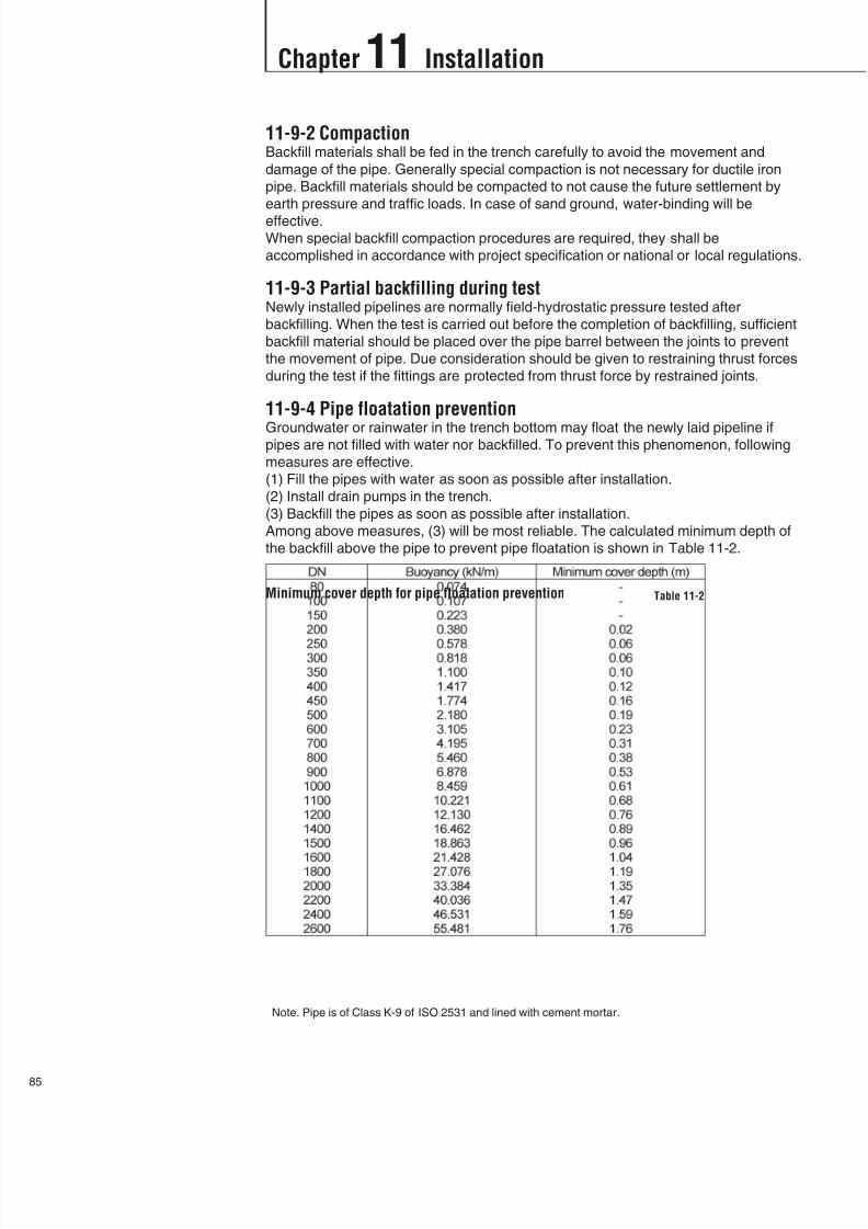
8/11/2019 Design Manual ductile iron
http://slidepdf.com/reader/full/design-manual-ductile-iron 86/138
5
Chapter 11 Installation
11-9-2 CompactionBackfill materials shall be fed in the trench carefully to avoid the movement and
damage of the pipe. Generally special compaction is not necessary for ductile iron
pipe. Backfill materials should be compacted to not cause the future settlement by
earth pressure and traffic loads. In case of sand ground, water-binding will be
effective.
When special backfill compaction procedures are required, they shall be
accomplished in accordance with project specification or national or local regulations.
11-9-3 Partial backfilling during testNewly installed pipelines are normally field-hydrostatic pressure tested after
backfilling. When the test is carried out before the completion of backfilling, sufficient
backfill material should be placed over the pipe barrel between the joints to prevent
the movement of pipe. Due consideration should be given to restraining thrust forces
during the test if the fittings are protected from thrust force by restrained joints.
11-9-4 Pipe floatation prevention
Groundwater or rainwater in the trench bottom may float the newly laid pipeline ifpipes are not filled with water nor backfilled. To prevent this phenomenon, following
measures are effective.
(1) Fill the pipes with water as soon as possible after installation.
(2) Install drain pumps in the trench.
(3) Backfill the pipes as soon as possible after installation.
Among above measures, (3) will be most reliable. The calculated minimum depth of
the backfill above the pipe to prevent pipe floatation is shown in Table 11-2.
Minimum cover depth for pipe floatation prevention Table 11-2
Note. Pipe is of Class K-9 of ISO 2531 and lined with cement mortar.

8/11/2019 Design Manual ductile iron
http://slidepdf.com/reader/full/design-manual-ductile-iron 87/138
86
12-1 General
12-2 Type of Joint
There are many types of joints for ductile iron pipes and fittings such as flexible type,
restrained type, self-anchoring flexible type and flange type.
These joints except for the flange type have the following general features.
(1) Because of the "self-sealing effect" of the rubber gasket, joints have excellent
water tightness.
(2) Pipe jointing work can be carried out in narrow trenches and even in places where
a small amount of water exists.
(3) Pipe installation work is fast compared to other pipeline with welded joints, and
pipe backfilling work can be carried out immediately after jointing.
12-2-1 Flexible type jointThere are two flexible type joints, namely, push-on (T-type) and mechanical (K-type)
joints. These joints allow angular deflection and expansion/contraction.
Push-on T-type joint (DN80 – DN600) Fig. 12-1
Push-on T-type joint (DN700 – DN2000) Fig.12-2
Mechanical K-type joint (DN80 – DN2600) Fig.12-3
Chapter 12 Jointing
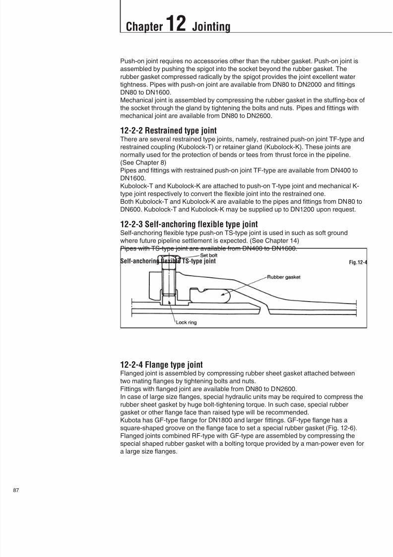
8/11/2019 Design Manual ductile iron
http://slidepdf.com/reader/full/design-manual-ductile-iron 88/138
7
Chapter 12 Jointing
Push-on joint requires no accessories other than the rubber gasket. Push-on joint is
assembled by pushing the spigot into the socket beyond the rubber gasket. The
rubber gasket compressed radically by the spigot provides the joint excellent water
tightness. Pipes with push-on joint are available from DN80 to DN2000 and fittings
DN80 to DN1600.
Mechanical joint is assembled by compressing the rubber gasket in the stuffing-box of
the socket through the gland by tightening the bolts and nuts. Pipes and fittings with
mechanical joint are available from DN80 to DN2600.
12-2-2 Restrained type jointThere are several restrained type joints, namely, restrained push-on joint TF-type and
restrained coupling (Kubolock-T) or retainer gland (Kubolock-K). These joints are
normally used for the protection of bends or tees from thrust force in the pipeline.
(See Chapter 8)
Pipes and fittings with restrained push-on joint TF-type are available from DN400 to
DN1600.
Kubolock-T and Kubolock-K are attached to push-on T-type joint and mechanical K-
type joint respectively to convert the flexible joint into the restrained one.Both Kubolock-T and Kubolock-K are available to the pipes and fittings from DN80 to
DN600. Kubolock-T and Kubolock-K may be supplied up to DN1200 upon request.
12-2-3 Self-anchoring flexible type jointSelf-anchoring flexible type push-on TS-type joint is used in such as soft ground
where future pipeline settlement is expected. (See Chapter 14)
Pipes with TS-type joint are available from DN400 to DN1600.
12-2-4 Flange type jointFlanged joint is assembled by compressing rubber sheet gasket attached between
two mating flanges by tightening bolts and nuts.
Fittings with flanged joint are available from DN80 to DN2600.In case of large size flanges, special hydraulic units may be required to compress the
rubber sheet gasket by huge bolt-tightening torque. In such case, special rubber
gasket or other flange face than raised type will be recommended.
Kubota has GF-type flange for DN1800 and larger fittings. GF-type flange has a
square-shaped groove on the flange face to set a special rubber gasket (Fig. 12-6).
Flanged joints combined RF-type with GF-type are assembled by compressing the
special shaped rubber gasket with a bolting torque provided by a man-power even for
a large size flanges.
Self-anchoring flexible TS-type joint Fig.12-4

8/11/2019 Design Manual ductile iron
http://slidepdf.com/reader/full/design-manual-ductile-iron 89/138
12-3 JointingProcedure
Chapter 12 Jointing
88
12-3-1 Push-on jointAssembling of push-on joint is very simple. Rubber gasket is placed on the inside of
socket, then spigot of pipe to be jointed is inserted into the socket.
Jointing procedure is as follows:
(1) Clean the groove in the socket thoroughly. Set the rubber gasket while checking
that it faces correct direction and is properly seated.1) Rubber gasket setting (Small to medium diameter size)
Form the rubber gasket into heart- or guitar-shape and set it on the socket
inside as shown in Fig. 12-7-2 and 12-8-2. Confirm that the rubber gasket is set
in the groove all around the circumference of the socket.
Flanged joint (RF-type) Fig.12-5
Flanged joint (RF-type and GF-type) Fig.12-6
DN80 - DN600 Fig. 12-7-1 Fig. 12-7-2
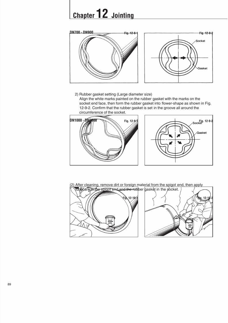
8/11/2019 Design Manual ductile iron
http://slidepdf.com/reader/full/design-manual-ductile-iron 90/138

8/11/2019 Design Manual ductile iron
http://slidepdf.com/reader/full/design-manual-ductile-iron 91/138
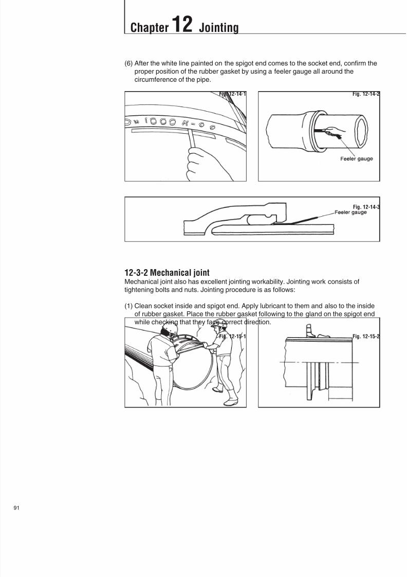
8/11/2019 Design Manual ductile iron
http://slidepdf.com/reader/full/design-manual-ductile-iron 92/138
Chapter 12 Jointing
1
(6) After the white line painted on the spigot end comes to the socket end, confirm the
proper position of the rubber gasket by using a feeler gauge all around the
circumference of the pipe.
12-3-2 Mechanical jointMechanical joint also has excellent jointing workability. Jointing work consists of
tightening bolts and nuts. Jointing procedure is as follows:
(1) Clean socket inside and spigot end. Apply lubricant to them and also to the insideof rubber gasket. Place the rubber gasket following to the gland on the spigot end
while checking that they face correct direction.
Fig. 12-14-1 Fig. 12-14-2
Fig. 12-15-1 Fig. 12-15-2
Fig. 12-14-3

8/11/2019 Design Manual ductile iron
http://slidepdf.com/reader/full/design-manual-ductile-iron 93/138
Chapter 12 Jointing
92
(2) Insert the spigot into the socket, then push the rubber gasket firmly and evenly
into the socket Keep the joint straight during assembly.
(3) Pull the gland toward the socket and push the rubber gasket. Attach T-head boltand hand- tighten nuts.
(4) Tighten the bolts to the normal range of bolting torque as indicated in Table 12-1
while at all times maintaining approximately the same distance between the gland
and socket flange at all points around the socket. This can be accomplished by
partially tightening the bolt at the bottom first, second the top, then the both sides,
and finally remainings. Repeat this process until all bolts are within the appropriate
range of torque. For large size pipes, five or more repetitions may be required.
Fig. 12-16
Fig. 12-17
Fig. 12-18
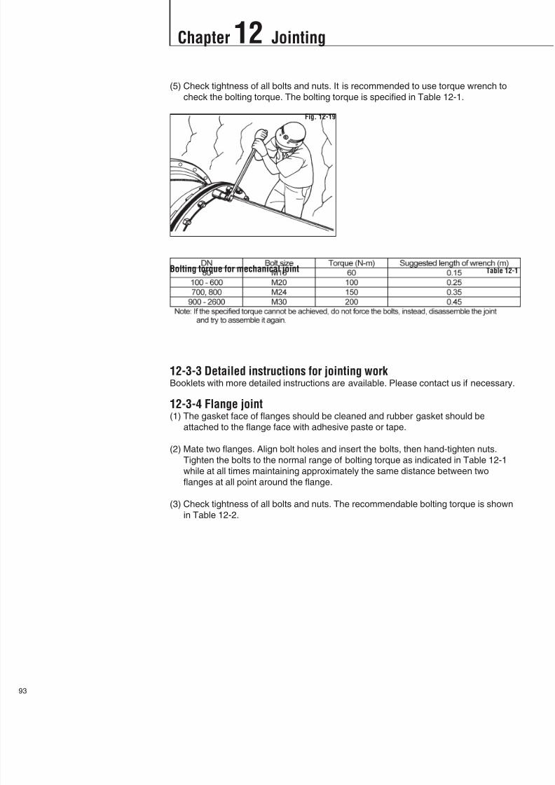
8/11/2019 Design Manual ductile iron
http://slidepdf.com/reader/full/design-manual-ductile-iron 94/138
Chapter 12 Jointing
3
(5) Check tightness of all bolts and nuts. It is recommended to use torque wrench to
check the bolting torque. The bolting torque is specified in Table 12-1.
12-3-3 Detailed instructions for jointing workBooklets with more detailed instructions are available. Please contact us if necessary.
12-3-4 Flange joint(1) The gasket face of flanges should be cleaned and rubber gasket should be
attached to the flange face with adhesive paste or tape.
(2) Mate two flanges. Align bolt holes and insert the bolts, then hand-tighten nuts.
Tighten the bolts to the normal range of bolting torque as indicated in Table 12-1
while at all times maintaining approximately the same distance between two
flanges at all point around the flange.
(3) Check tightness of all bolts and nuts. The recommendable bolting torque is shown
in Table 12-2.
Fig. 12-19
Bolting torque for mechanical joint Table 12-1
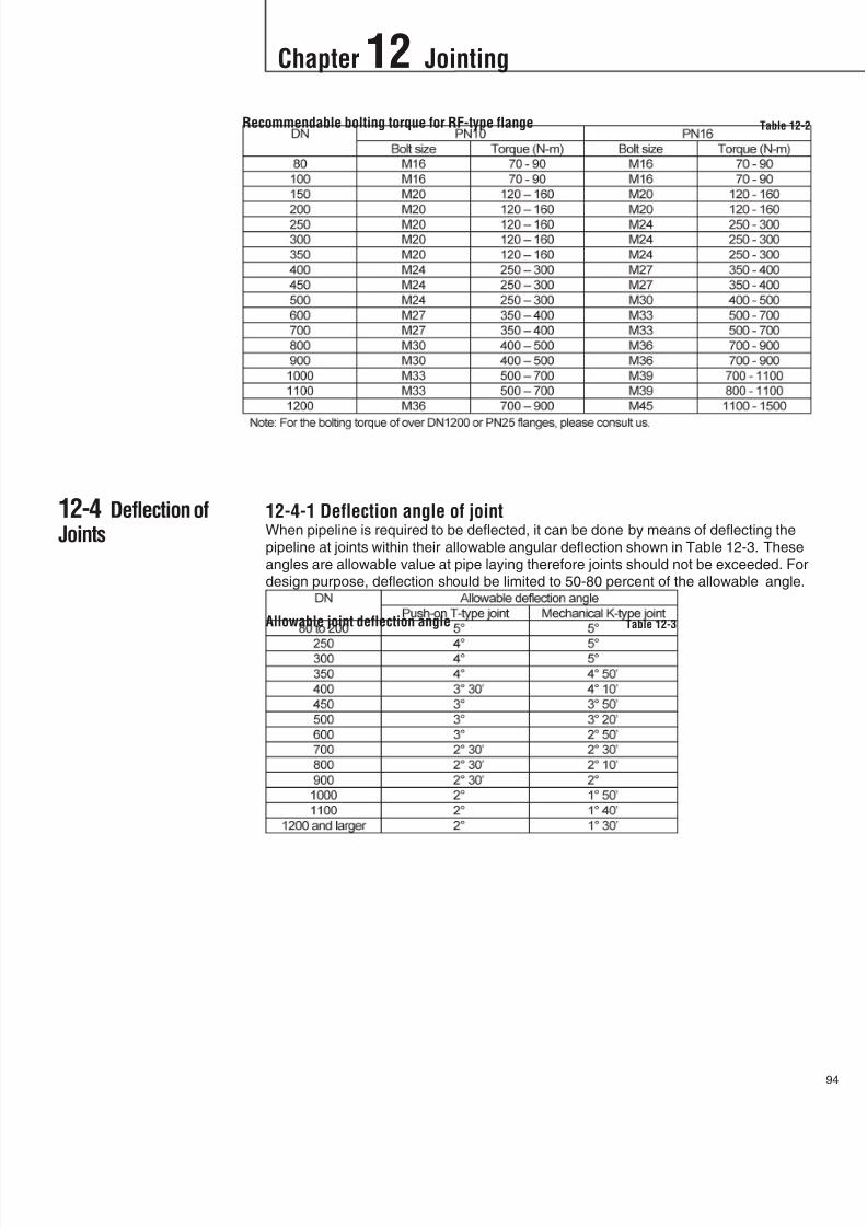
8/11/2019 Design Manual ductile iron
http://slidepdf.com/reader/full/design-manual-ductile-iron 95/138

8/11/2019 Design Manual ductile iron
http://slidepdf.com/reader/full/design-manual-ductile-iron 96/138
Chapter 12 Jointing
5
12-4-2 Procedure of pipe jointing in deflection(1) Make the trench wider appropriate for the amount of deflection.
(2) Assemble the joint in a straight line, then deflect the joint up to the allowable angle
shown in Table 12-3.
(3) In case of push-on joint, whole two white lines on the spigot should not be visible
all around the pipe body after deflected.
In case of mechanical joint, bolts shall be tightened slightly after deflected, then
completely tightened to the specified bolting torque.
12-4-3 Laying of pipes in curveIt is often necessary to deviate the pipeline from a straight line when following the
curvature of streets and roads.
When the deviation angle is small or when the deviation angle is large but the radius
of curvature is large, both push-on and mechanical joint pipes may lend themselves
readily to deflection of pipelines at the joints within their allowable deflection angle.
(See Fig. 12-20)
When the deviation angle is large and the radius of curvature is small, bends shall be
used. The standard angle of the bend is 90, 45, 22.5 and 11.25. Pipeline routewill be decided by the combination of bend(s) and joint deflection.
Offset: S
Where, L : Length of pipe (m)
: Deflection angle (degree)
Radius of curve: R
Fig. 12-20
L
SR

8/11/2019 Design Manual ductile iron
http://slidepdf.com/reader/full/design-manual-ductile-iron 97/138
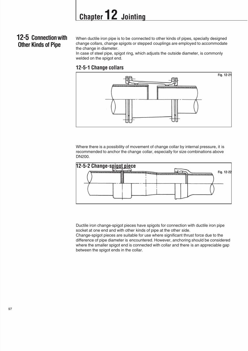
8/11/2019 Design Manual ductile iron
http://slidepdf.com/reader/full/design-manual-ductile-iron 98/138
Chapter 12 Jointing
7
12-5 Connection withOther Kinds of Pipe
When ductile iron pipe is to be connected to other kinds of pipes, specially designed
change collars, change spigots or stepped couplings are employed to accommodate
the change in diameter.
In case of steel pipe, spigot ring, which adjusts the outside diameter, is commonly
welded on the spigot end.
12-5-1 Change collars
Where there is a possibility of movement of change collar by internal pressure, it is
recommended to anchor the change collar, especially for size combinations above
DN200.
12-5-2 Change-spigot piece
Ductile iron change-spigot pieces have spigots for connection with ductile iron pipe
socket at one end and with other kinds of pipe at the other side.
Change-spigot pieces are suitable for use where significant thrust force due to the
difference of pipe diameter is encountered. However, anchoring should be considered
where the smaller spigot end is connected with collar and there is an appreciable gapbetween the spigot ends in the collar.
Fig. 12-22
Fig. 12-21
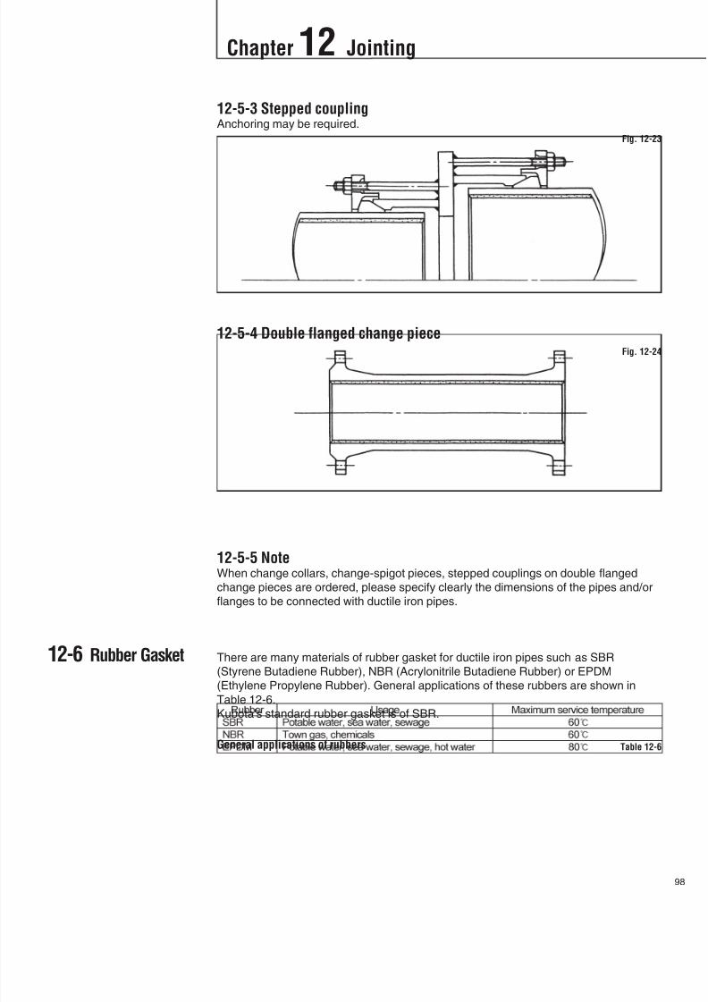
8/11/2019 Design Manual ductile iron
http://slidepdf.com/reader/full/design-manual-ductile-iron 99/138
12-6 Rubber Gasket
12-5-3 Stepped couplingAnchoring may be required.
12-5-4 Double flanged change piece
12-5-5 NoteWhen change collars, change-spigot pieces, stepped couplings on double flanged
change pieces are ordered, please specify clearly the dimensions of the pipes and/or
flanges to be connected with ductile iron pipes.
There are many materials of rubber gasket for ductile iron pipes such as SBR
(Styrene Butadiene Rubber), NBR (Acrylonitrile Butadiene Rubber) or EPDM
(Ethylene Propylene Rubber). General applications of these rubbers are shown in
Table 12-6.Kubota's standard rubber gasket is of SBR.
Chapter 12 Jointing
98
Fig. 12-23
Fig. 12-24
General applications of rubbers Table 12-6

8/11/2019 Design Manual ductile iron
http://slidepdf.com/reader/full/design-manual-ductile-iron 100/138
Chapter 13 Field Hydrostatic Test
9
13-1 General
13-2 Flow Chart ofHydrostatic Test
A newly installed pipeline may be tested to check the reliability of its performance
before being brought into service.
Field hydrostatic test for ductile iron pipeline is specified in ISO 10802.
The flow chart of the field hydrostatic test is shown below.
Flow chart of field hydrostatic test Fig. 13-1

8/11/2019 Design Manual ductile iron
http://slidepdf.com/reader/full/design-manual-ductile-iron 101/138
13-3 Details of EachStep
13-3-1 Decision of test sectionThe test section should be decided on after considering piping conditions and site
situations, for example, ups and downs of pipeline, position of stop valves and air
relief valves, space for testing, availability of water for the test, numbers of joints, and
other factors. While the test section is being determined, the position of the valves
and valve chambers should be considered, because they may be useful as terminal
points for the ends of the test section as shown in Fig. 13-2.
cf. ISO 10802, Sec. 4.1
4.1.2 For pressure pipelines, the length of the test sections shall not exceed 1500 m
unless otherwise specified.4.1.3 For non-pressure pipelines, the test section is usually the total length between
consecutive manholes or inspection points. If special arrangements are made to
enable testing over only part of length between manholes and inspection points,
then the length of the test section shall not exceed 1000 m unless otherwise
specified.
13-3-2 Decision of test pressureThe test pressure should be determined referring to international standard or national
standard.
cf. ISO 10802, Sec. 5.1.1.3 (for pressure pipeline) and 5.2.2 (for non-pressure
pipeline)5.1.1.3 The test pressure at the lowest point of the test section shall be not less than
the limit specified in a) or b), whichever is greater.
a) for working pressure less than or equal to 10 bar: 1.5 times the working
pressure;
for working pressure greater than 10 bar: the working pressure plus 5 bar;
b) the maximum working pressure
The test pressure shall not exceed
- the maximum test pressure specified in the standards applicable to pipes,
fittings, flanges and accessories, or
- the design pressure of the restraining or anchoring devices.
5.1.1.4 The test pressure at the highest point of the test section shall not be less than
the working pressure at this point.
Chapter 13 Field Hydrostatic Test
10
Example of terminal point for the end of test section Fig. 13-2
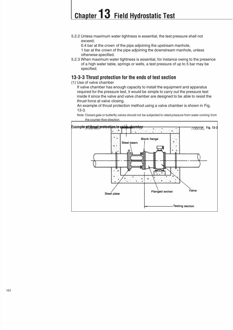
8/11/2019 Design Manual ductile iron
http://slidepdf.com/reader/full/design-manual-ductile-iron 102/138
Chapter 13 Field Hydrostatic Test
1
5.2.2 Unless maximum water tightness is essential, the test pressure shall not
exceed;
0.4 bar at the crown of the pipe adjoining the upstream manhole,
1 bar at the crown of the pipe adjoining the downstream manhole, unless
otherwise specified.
5.2.3 When maximum water tightness is essential, for instance owing to the presence
of a high water table, springs or wells, a test pressure of up to 5 bar may be
specified.
13-3-3 Thrust protection for the ends of test section(1) Use of valve chamber
If valve chamber has enough capacity to install the equipment and apparatus
required for the pressure test, it would be simple to carry out the pressure test
inside it since the valve and valve chamber are designed to be able to resist the
thrust force at valve closing.
An example of thrust protection method using a valve chamber is shown in Fig.
13-3.
Note: Closed gate or butterfly valves should not be subjected to rated pressure from water coming fromthe counter-flow direction.
Example of thrust protection in valve chamber Fig. 13-3

8/11/2019 Design Manual ductile iron
http://slidepdf.com/reader/full/design-manual-ductile-iron 103/138
(2) Other thrust protection
An example of the thrust protection method other than that in valve chamber is
shown in Fig. 13-4.
For low pressure or small diameter pipeline, portable steel plate with reinforcedbeams or wooden timbers can be used instead of concrete blocks as shown in Fig.
13-5.
Care should be taken to the strength of the thrust protection.
Chapter 13 Field Hydrostatic Test
10
Example of thrust protection Fig. 13-4
Example of thrust protection Fig. 13-5

8/11/2019 Design Manual ductile iron
http://slidepdf.com/reader/full/design-manual-ductile-iron 104/138
Chapter 13 Field Hydrostatic Test
3
13-3-4 Water fillingWater filling shall be carried out slowly verifying that air is being released from the
pipeline. It is very important to make sure that air is actually being released during the
water filling. Insufficient ventilation will lead the test to fail and compressed air by the
water pressure is very dangerous.
If leakage is found during the water filling, leaked point should be repaired
immediately.
The pipeline should be left in the water-filled condition for at least 24 hours to stabilize
the pipeline.
cf. ISO 10802, Sec. 4.4
Filling should normally be carried out at the lowest point of the section to be tested
and at a rate slow enough to ensure that all air is evacuated. The pipeline shall have
air-venting facilities at all high points. As a guide, the flow-rate during filling should not
exceed 10 % of the design working flow-rate. Cement mortar lined pipelines require a
period of time after filling (depending on site conditions) for absorption by the lining to
take place.
13-3-5 Installation of test equipmentThe necessary equipment for the pressure testing work will be as follows.
- Pressure pump (with engine or motor) 1 set
- Pressure gauge 1 set
- Pressure recorder 1 set
- Suction hose necessary length
- Connection hose necessary length
- Overflow hose necessary length
- Water tank and water meter1 set
- Connection pieces (including valves or cocks) 1 set
An example of the layout of test equipment is shown in Fig. 13-6.
Example of layout of test equipment Fig. 13-6
8/11/2019 Design Manual ductile iron
http://slidepdf.com/reader/full/design-manual-ductile-iron 105/138
13-3-6 TestingThe pressure test should be carried out referring to the international standard or
national standard.
cf. ISO 10802, Sec. 5
5.1 Pressure pipeline
5.1.1 Preliminary operations
After filling and before application of the test pressure, maintain the test section at
the working pressure for a sufficient period of time for it to stabilize with respect to
line movement under pressure, water absorption by the lining, etc.
5.1.2.1 Falling pressure test
Maintain the test pressure constant to0.1 bar, by pumping if necessary, for a
period of at least 1 h. Then disconnect the pump and allow no further water to
enter the test section for a period of at least
1 h for DN600, 3 h for 600DN1400, 6 h for DN1400
At the end of this test period, measure the pressure in the test section. Determine
the water loss either by measuring (to an accuracy of5 %) the amount of water
it is necessary to pump into the test section to restore the test pressure to within0.1 bar, or by restoring the test pressure and measuring the amount of water it
is necessary to draw off the test section to produce an equivalent pressure drop.
5.1.2.2 Constant pressure test
Maintain the test pressure constant to0.1 bar, by pumping if necessary, for a
period of at least 1 h. Then maintain the test pressure constant (to0.1 bar) in
the test section by pumping for at least
1 h for DN600, 3 h for 600DN1400, 6 h for DN1400
and measure (to an accuracy of 5 %) the amount of water used to do so.
5.2 Non-pressure pipeline
5.2.1 After filling and before application of the test pressure, leave the test section for
a sufficient period of time to allow water absorption by the lining.
5.2.4 After a test period of 2 h, determine the water loss by measuring the quantity of
water it is necessary to add to restore the initial level in the upstream manhole.
13-3-7 JudgementThe judgement for the pressure test should be done referring to the international
standard or national standard.
cf. ISO 10802, Sec. 6
6.1 Pressure pipelines
The water loss shall not exceed 0.001 litre/hour/kilometer of pipeline/millimetre of
nominal size/bar of static pressure (average head applied to the test section).
6.2 Non-pressure pipelines
The water loss shall not exceed 0.1 litre/kilometer of pipeline/millimetre of nominal
size. However, when a test pressure in excess of 1 bar is specified, theacceptance criterion is that of pressure pipelines.
13-3-8 DrainageAfter the completion of the test, water should be drained from the pipeline. If the
adjacent pipeline section is to be tested, the water may be available for the next test.
13-3-9 Removal of thrust protectionThrust protections at the ends of the test section should be removed when the tested
pipeline is to be connected to adjacent pipeline. However, when the adjacent pipeline
will be tested these thrust protections may be available for it.
Chapter 13 Field Hydrostatic Test
10

8/11/2019 Design Manual ductile iron
http://slidepdf.com/reader/full/design-manual-ductile-iron 106/138
Chapter 13 Field Hydrostatic Test
5
13-3-10 Connection to adjacent pipelineAfter the adjacent pipeline has been tested, the test section should be connected to it.
Examples of the connection are shown below.
Example of connection at valve chamber Fig. 13-7
Example of connection Fig. 13-8

8/11/2019 Design Manual ductile iron
http://slidepdf.com/reader/full/design-manual-ductile-iron 107/138
14-1 General
14-2 Investigation
When pipes are laid in extremely soft ground consisting of hydrous and porous soil or
in reclaimed land, special care should be taken to minimize the effect of ground
movement on the pipeline.
Generally, soft ground is prone to subside for various reasons, for example,
consolidation caused by pumping out underground water, banking for road-widening,
loads and vibrations of vehicles, and effects of other constructions.
Therefore, pipelines to be installed in soft ground are required to be able to adapt to
ground movement.
Ground studies on the planned pipeline route should be made well in advance. The
investigation of properties in each stratum should be made vertically to obtain
samples by boring, to carry out soil tests, to measure N-values, etc.
Horizontally, it is desirable to set up test points taking the followings into
consideration;
1) geographical features and formation process of soft ground,2) long intervals where the stratum of the ground is equal, and
3) short intervals in irregular places, for example at the transitional point between
solid ground and soft ground
It is also very effective to refer to the soil study results of previous construction work
carried out in the same vicinity.
Chapter 14 Piping in Soft Ground
10
Sectional view of typical strata of soft ground Fig. 14-1

8/11/2019 Design Manual ductile iron
http://slidepdf.com/reader/full/design-manual-ductile-iron 108/138
Chapter 14 Piping in Soft Ground
7
14-3 Calculation ofSettlement Amount
The assumed amount of settlement at each point of the planned pipeline route should
be checked on the basis of soil investigation results.
There are three calculation formulas for the settlement.
Where, : Amount of settlement due to consolidation (m)
eo : Initial void ratio of undisturbed ground
e : Void ratio after loading
H : Thickness of strata to be consolidated (m)
mv : Volume change of soil (coefficient of volume compressibility) (m2
/kN)Cc : Compression index of soil
P : Preceding load of undisturbed soil (kN/m2)
P : Increased load (kN/m2)
I : Influence value by depth
W : Increased load (kN/m2)
The following is an example of calculation used to estimate the amount of settlement
when pipe is laid in soft ground.
(1) Conditions
Pipe: DN1000 ductile iron pipe, Class K-9Ground: Soft ground (unit weight of soil= 10 kN/m3)
The value of mv at each layer is shown in Fig. 14-2.
Excavation: Width 2.2 m, earth cover depth: 1.5 m
Backfilling: with sand (unit weight= 18 kN/m3)
Conditions of the calculation Fig. 14-2
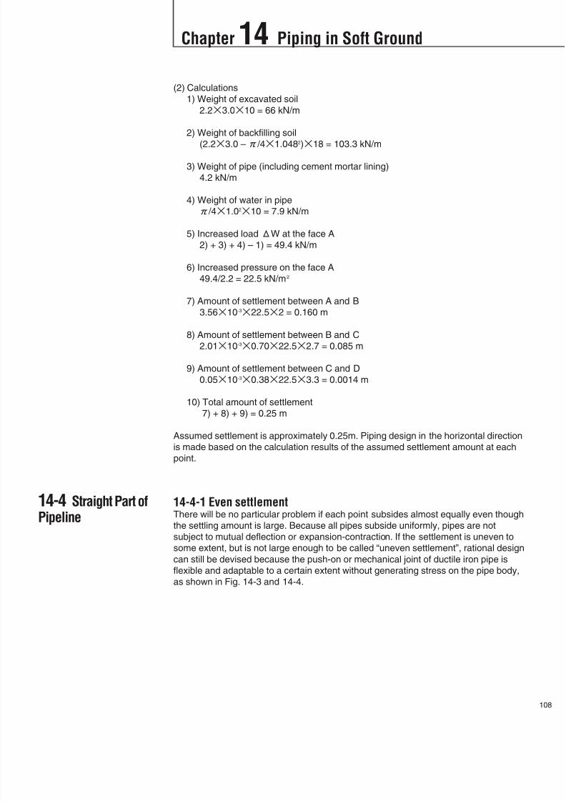
8/11/2019 Design Manual ductile iron
http://slidepdf.com/reader/full/design-manual-ductile-iron 109/138
14-4 Straight Part ofPipeline
(2) Calculations
1) Weight of excavated soil
2.23.010 = 66 kN/m
2) Weight of backfilling soil
(2.23.0 – /41.0482)18 = 103.3 kN/m
3) Weight of pipe (including cement mortar lining)
4.2 kN/m
4) Weight of water in pipe
/41.0210 = 7.9 kN/m
5) Increased loadW at the face A
2) + 3) + 4) – 1) = 49.4 kN/m
6) Increased pressure on the face A
49.4/2.2 = 22.5 kN/m2
7) Amount of settlement between A and B
3.5610-322.52 = 0.160 m
8) Amount of settlement between B and C
2.0110-30.7022.52.7 = 0.085 m
9) Amount of settlement between C and D
0.0510-30.3822.53.3 = 0.0014 m
10) Total amount of settlement
7) + 8) + 9) = 0.25 m
Assumed settlement is approximately 0.25m. Piping design in the horizontal direction
is made based on the calculation results of the assumed settlement amount at each
point.
14-4-1 Even settlementThere will be no particular problem if each point subsides almost equally even though
the settling amount is large. Because all pipes subside uniformly, pipes are not
subject to mutual deflection or expansion-contraction. If the settlement is uneven to
some extent, but is not large enough to be called “uneven settlement”, rational design
can still be devised because the push-on or mechanical joint of ductile iron pipe isflexible and adaptable to a certain extent without generating stress on the pipe body,
as shown in Fig. 14-3 and 14-4.
Chapter 14 Piping in Soft Ground
10

8/11/2019 Design Manual ductile iron
http://slidepdf.com/reader/full/design-manual-ductile-iron 110/138
Chapter 14 Piping in Soft Ground
9
Where, : Amount of deflection
L : Length of pipe
: Deflection angle of joint (See Table 12-3)
Note. As for Amount of deflection and deflection angle of the joints, see Table 12-4 and 12-5.
Where, n : Number of pipes to the maximum settlement point (odd number)
An example of the amount of pipeline settlement by successive joint deflection on
90m long pipeline by 6m long pipe is shown in Table 14-1.
The maximum expansion of push-on joint and mechanical joint is shown in Table 14-2
and Fig. 14-5.
Deflection of joint Fig. 14-3
Adaptability of flexible joint to pipe settlement Fig. 14-4
Example of adaptable pipeline settlement (6m long pipe, 90m long pipeline) Table 14-1

8/11/2019 Design Manual ductile iron
http://slidepdf.com/reader/full/design-manual-ductile-iron 111/138
Chapter 14 Piping in Soft Ground
11
Maximum expansion of joints Table 14-2
Fig. 14-5

8/11/2019 Design Manual ductile iron
http://slidepdf.com/reader/full/design-manual-ductile-iron 112/138
Chapter 14 Piping in Soft Ground
1
14-4-2 Uneven settlementSettlement differences of pipeline will occur;
1) in areas that have a variety of thickness in lower consolidation strata,
2) at the boundary of structures which do not subside and soft ground, and
3) where solid ground changes to soft ground.
In case of uneven settlement, it is first necessary to estimate the settlement
differences. It is especially important to make calculations based on data obtained
through soil studies as mentioned earlier. Countermeasures should be implemented
as follows according to the results of the calculations.
(1) Small uneven settlement
There is no need to give particular consideration if final uneven settlement is able
to be absorbed by the pipe joints only. Pipes should be jointed within a half of the
allowable deflection angle. If there is a possibility that even settlement is greater
than assumed values because of uncertain factors such as inadequate boring
data, application of collars might be examined as a countermeasure.
(2) Large uneven settlementIf uneven settlement cannot be absorbed by the pipe joints only, examination for
next countermeasures should be carried out to determine whether it can be
absorbed by collars or not. Collars have twice the allowable deflection angle of
mechanical joint and also a large amount of expansion (See Table 14-3).
Generally a number of collars should be configured in the design.
Maximum expansion of K-type joint collar Table 14-3
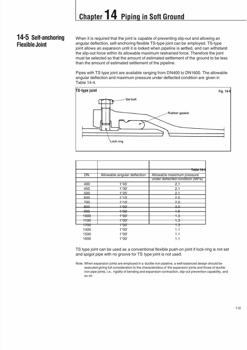
8/11/2019 Design Manual ductile iron
http://slidepdf.com/reader/full/design-manual-ductile-iron 113/138

8/11/2019 Design Manual ductile iron
http://slidepdf.com/reader/full/design-manual-ductile-iron 114/138
Chapter 14 Piping in Soft Ground
3
14-6 Curved Parts ofPipeline
14-7 Precaution forPipe Laying
Pipelines invariably have vertically or horizontally curved stretches in the main or
branch pipeline. These deflected points cause thrust force due to the internal
pressure therefore is protected with concrete blocks in principle. However in
extremely soft ground, concrete blocks might cause uneven settlement of the
pipeline. Consequently, it is necessary to arrange the design so that the weight of
these parts is equal to that of straight parts of the pipeline. A design using restrained
joints should be made as described in Chapter 8.
The followings are very important points to be considered when laying pipes in soft
ground.
14-7-1 Pipe installationIt is important to prevent ground softening by kneading of the soil at pipeline
installation especially in case of extremely hydrous clayey soil. It is also important to
correct any improperly declining pipes or deflected joints at each occurrence.
It is highly recommendable making a sand bed on the trench bottom.
14-7-2 BackfillingPipeline settlement is particularly great during and just after backfilling so that it is
important to backfill pipes evenly and carefully. In some situations, it may be
necessary to suspend pipes by wire ropes during backfilling. After the completion of
backfilling, it is advisable not to place excavated soil, heavy machines or mechanical
equipment over the pipes so as to prevent irregular pipeline settlement.
14-7-3 Removal of sheetingWhen the trench wall is protected by sheeting, care should be paid at the sheeting
removal. The problem here is that, in some situations, carefully installed pipes move
from their established position when sheeting is removed. One countermeasure is the
selection of removing method after careful consideration of the ground features.Special attention should be given to the differences in the ground level on either side
of the installed pipeline. Depending on the circumstances, grouting method may have
to be employed simultaneously.
14-7-4 Floating of pipesAdditionally in soft ground, there are many cases where water table is so high that the
empty pipes are apt to float. Backfilling at an early stage is effective in preventing this
phenomenon. It is further advisable to fill the pipes with water as soon as possible
after installed. (Refer to Section 11-9-4)
14-7-5 Corrosion prevention
Generally soft ground areas include coastal reclaimed lands, sludge areas, peatareas, etc.. At these sites the water table will be high and soil will be very corrosive.
Therefore at the planning stage and during the soil studies, the corrosiveness of the
soil should be evaluated by means of boring and soil test. If necessary, special
corrosion prevention measures should be applied externally to the pipes.
Polyethylene sleeving method is usually used as an additional corrosion prevention
measure for ductile iron pipes. (Refer to Section 9-2)

8/11/2019 Design Manual ductile iron
http://slidepdf.com/reader/full/design-manual-ductile-iron 115/138

8/11/2019 Design Manual ductile iron
http://slidepdf.com/reader/full/design-manual-ductile-iron 116/138
Chapter 15 Piping under Special Conditions
5
15-1-3 Allowable resistance force of jacking pipePipes shall be jacked within the allowable resistance force of the jacking pipe given in
the below table.
Note The above values should be distributed evenly around the circumference of the pipe.
General arrangement of pipe jacking equipment Fig. 15-3
DN Class 1 Class 2 Class 3 Class K9 Class K10 Class K11
300 2,060 - 1,770 - - -
350 2,450 - 1,770 - - -
400 2,840 2,450 2,160 - - -
450 2,840 2,840 2,450 - - -
500 3,730 3,330 2,840 - - -
600 3,730 3,730 3,730 - - -
700 6,570 5,790 4,810 4,540 5,870 6,570
800 6,570 6,570 5,790 5,410 6,570 6,570
900 6,570 6,570 6,570 6,350 6,570 6,5701000 9,020 9,020 8,040 7,360 9,020 9,020
1100 9,020 9,020 9,020 8,450 9,020 9,020
1200 9,020 9,020 9,020 9,020 9,020 9,020
1400 9,020 9,020 9,020
1500 12,360 12,360 12,360 12,360 12,360 12,360
1600 12,360 12,360 12,360 12,360 12,360 12,360
1800 12,360 12,360 12,360 - - -
2000 18,670 18,670 18,670 - - -
2200 18,670 18,670 18,670 - - -
2400 18,670 18,670 18,670 - - -
2600 23,240 23,240 23,240 - - -
Class of pipe by Japanese standard Class of pipe by ISO standard
Allowable resistance force (kN)
Allowable resistance force of jacking ductile iron pipe Table 15-1
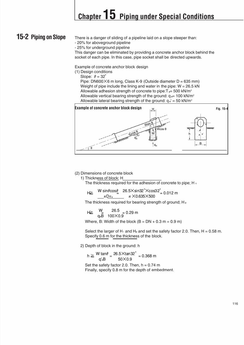
8/11/2019 Design Manual ductile iron
http://slidepdf.com/reader/full/design-manual-ductile-iron 117/138
15-2 Piping on Slope There is a danger of sliding of a pipeline laid on a slope steeper than:
- 20% for aboveground pipeline
- 25% for underground pipeline
This danger can be eliminated by providing a concrete anchor block behind the
socket of each pipe. In this case, pipe socket shall be directed upwards.
Example of concrete anchor block design
(1) Design conditions
Slope:= 32Pipe: DN6006 m long, Class K-9 (Outside diameter D = 635 mm)
Weight of pipe include the lining and water in the pipe: W = 26.5 kN
Allowable adhesion strength of concrete to pipe:Ta= 500 kN/m2
Allowable vertical bearing strength of the ground: qa= 100 kN/m2
Allowable lateral bearing strength of the ground: qa‘ = 50 kN/m2
(2) Dimensions of concrete block
1) Thickness of block: H
The thickness required for the adhesion of concrete to pipe; H1
The thickness required for bearing strength of ground; H2
Where, B: Width of the block (B = DN + 0.3 m = 0.9 m)
Select the larger of H1 and H2 and set the safety factor 2.0. Then, H = 0.58 m.
Specify 0.6 m for the thickness of the block.
2) Depth of block in the ground: h
Set the safety factor 2.0. Then, h = 0.74 m
Finally, specify 0.8 m for the depth of embedment.
Chapter 15 Piping under Special Conditions
11
Example of concrete anchor block design Fig. 15-4

8/11/2019 Design Manual ductile iron
http://slidepdf.com/reader/full/design-manual-ductile-iron 118/138
It is recommended that aboveground piping with socket and spigot pipes be provided
with one support per pipe. The pipe support should have a supporting angle of
between 90and 120and positioned just behind the socket of each pipe.
Pipes should be secured to the supports with steel straps and rubber band so that
axial movement due to expansion and contraction caused by temperature change is
absorbed at individual joint in the pipeline.
Fittings, such as bends and tees, which will produce thrust force due to internal
pressure, should be protected with anchorage.
Chapter 15 Piping under Special Conditions
7
15-3 AbovegroundPiping
Example of aboveground piping Fig. 15-5
Fig 15-6Pipe supporting angle

8/11/2019 Design Manual ductile iron
http://slidepdf.com/reader/full/design-manual-ductile-iron 119/138
For piping in tunnel, internal mechanical joint (U-type joint) offers following
advantages:
(1) All jointing works can be done at pipe inside so that the space between the inside
of tunnel and outside of pipes can be made minimal. This means pipe diameter
can be made maximum.
(2) Jointing work uses no fire or welding, therefore pipes can be jointed safely in the
tunnel.
(3) Assembling of mechanical joint is easy.
(4) U-type joint is flexible, therefore it will be possible to lay pipes according to the
curvature of the tunnel.
Pipes and fittings with U-type joint are ranged from DN700 to DN2600 and
manufactured in accordance with Japanese standard (JIS).
Chapter 15 Piping under Special Conditions
11
15-4 Piping in Tunnel
U-type joint Fig. 15-7
Example of in-tunnel piping Fig. 15-8

8/11/2019 Design Manual ductile iron
http://slidepdf.com/reader/full/design-manual-ductile-iron 120/138
There are two possibilities for river or channel crossing, i.e., over-crossing and under-
crossing. Over -crossing is by hanging the pipeline on a bridge or by water-bridge.
Under-crossing is by open-cut after shut the flow, pipe jacking, or shield method.
Note. An air release valve should be provided at the highest point in the aqueduct.
Chapter 15 Piping under Special Conditions
9
15-5 River Crossing
Example of aqueduct over bridge Fig. 15-9
Example of water bridge Fig. 15-10

8/11/2019 Design Manual ductile iron
http://slidepdf.com/reader/full/design-manual-ductile-iron 121/138
(1) It is recommended laying multiple pipelines for maintenance.
(2) Foundation work for under-crossing should be conducted with greatest care, most
durable materials, and most reliable construction techniques.
(3) For the protection, under-crossing pipeline should be covered with concrete. (See
Fig. 15-11) Other protective measures should be taken as necessary.
In recent years, when a water main is required to pass underneath a railway or road,
pipe jacking method or shield method is often employed to minimize the disturbance
of train or road traffic.
Pipes to be laid under a railway should be encased in protective devices such as
closed conduit, casing pipe, etc. to prevent direct impact or railway load andvibrations.
Chapter 15 Piping under Special Conditions
12
15-6 Railway andRoad Crossings
Example of railway crossing by casing method Fig. 15-12
Example of river-bed crossing Fig. 15-11
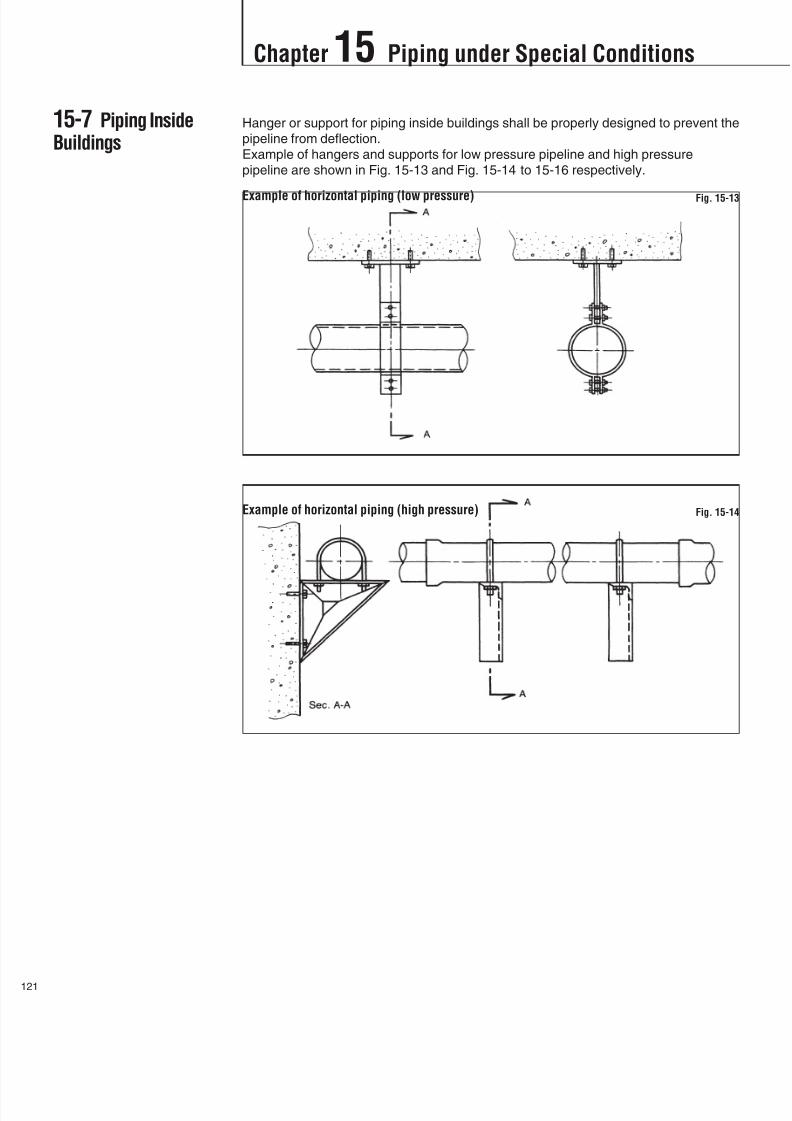
8/11/2019 Design Manual ductile iron
http://slidepdf.com/reader/full/design-manual-ductile-iron 122/138
Chapter 15 Piping under Special Conditions
1
Hanger or support for piping inside buildings shall be properly designed to prevent the
pipeline from deflection.
Example of hangers and supports for low pressure pipeline and high pressure
pipeline are shown in Fig. 15-13 and Fig. 15-14 to 15-16 respectively.
Example of horizontal piping (low pressure) Fig. 15-13
Example of horizontal piping (high pressure) Fig. 15-14
15-7 Piping InsideBuildings

8/11/2019 Design Manual ductile iron
http://slidepdf.com/reader/full/design-manual-ductile-iron 123/138

8/11/2019 Design Manual ductile iron
http://slidepdf.com/reader/full/design-manual-ductile-iron 124/138
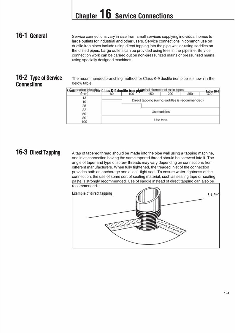
8/11/2019 Design Manual ductile iron
http://slidepdf.com/reader/full/design-manual-ductile-iron 125/138
Chapter 16 Service Connections
12
16-1 General
16-2 Type of ServiceConnections
16-3 Direct Tapping
Service connections vary in size from small services supplying individual homes to
large outlets for industrial and other users. Service connections in common use on
ductile iron pipes include using direct tapping into the pipe wall or using saddles on
the drilled pipes. Large outlets can be provided using tees in the pipeline. Service
connection work can be carried out on non-pressurized mains or pressurized mains
using specially designed machines.
The recommended branching method for Class K-9 ductile iron pipe is shown in the
below table.
A tap of tapered thread should be made into the pipe wall using a tapping machine,
and inlet connection having the same tapered thread should be screwed into it. The
angle of taper and type of screw threads may vary depending on connections from
different manufacturers. When fully tightened, the treaded inlet of the connection
provides both an anchorage and a leak-tight seal. To ensure water-tightness of the
connection, the use of some sort of sealing material, such as sealing tape or sealingpaste is strongly recommended. Use of saddle instead of direct tapping can also be
recommended.
Branching method for Class K-9 ductile iron pipe Table 16-1
Example of direct tapping Fig. 16-1
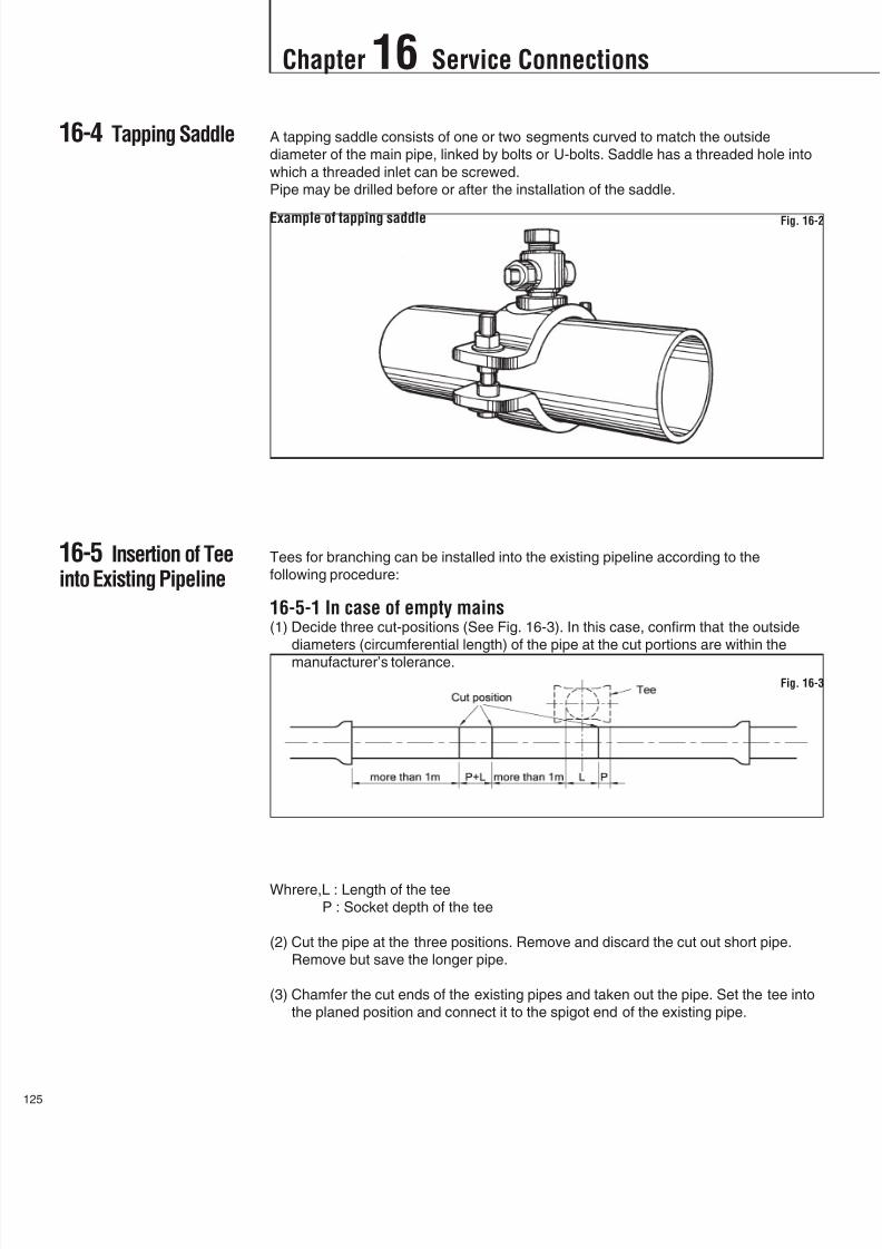
8/11/2019 Design Manual ductile iron
http://slidepdf.com/reader/full/design-manual-ductile-iron 126/138
Chapter 16 Service Connections
5
16-4 Tapping Saddle
16-5 Insertion of Teeinto Existing Pipeline
A tapping saddle consists of one or two segments curved to match the outside
diameter of the main pipe, linked by bolts or U-bolts. Saddle has a threaded hole into
which a threaded inlet can be screwed.
Pipe may be drilled before or after the installation of the saddle.
Tees for branching can be installed into the existing pipeline according to the
following procedure:
16-5-1 In case of empty mains(1) Decide three cut-positions (See Fig. 16-3). In this case, confirm that the outside
diameters (circumferential length) of the pipe at the cut portions are within the
manufacturer’s tolerance.
Whrere,L : Length of the tee
P : Socket depth of the tee
(2) Cut the pipe at the three positions. Remove and discard the cut out short pipe.
Remove but save the longer pipe.
(3) Chamfer the cut ends of the existing pipes and taken out the pipe. Set the tee into
the planed position and connect it to the spigot end of the existing pipe.
Example of tapping saddle Fig. 16-2
Fig. 16-3
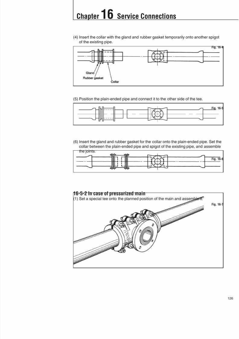
8/11/2019 Design Manual ductile iron
http://slidepdf.com/reader/full/design-manual-ductile-iron 127/138
Chapter 16 Service Connections
12
(4) Insert the collar with the gland and rubber gasket temporarily onto another spigot
of the existing pipe.
(5) Position the plain-ended pipe and connect it to the other side of the tee.
(6) Insert the gland and rubber gasket for the collar onto the plain-ended pipe. Set the
collar between the plain-ended pipe and spigot of the existing pipe, and assemble
the joints.
16-5-2 In case of pressurized main(1) Set a special tee onto the planned position of the main and assemble it.
Fig. 16-4
Fig. 16-5
Fig. 16-6
Fig. 16-7

8/11/2019 Design Manual ductile iron
http://slidepdf.com/reader/full/design-manual-ductile-iron 128/138
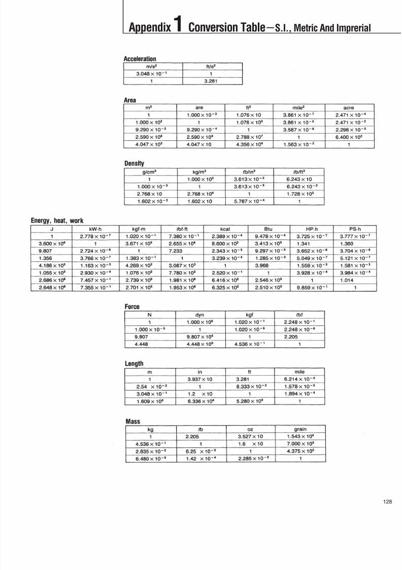
8/11/2019 Design Manual ductile iron
http://slidepdf.com/reader/full/design-manual-ductile-iron 129/138
Appendix 1 Conversion TableS.I., Metric And Imprerial
12
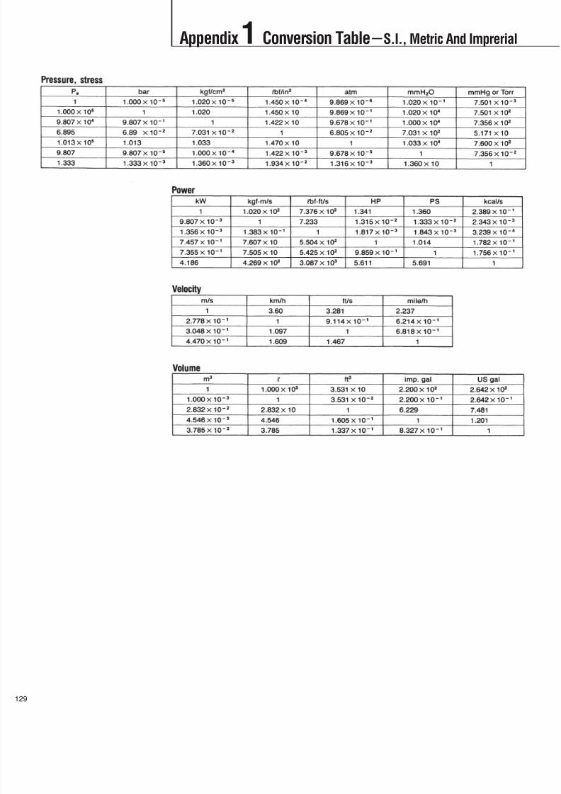
8/11/2019 Design Manual ductile iron
http://slidepdf.com/reader/full/design-manual-ductile-iron 130/138
Appendix1 Conversion TableS.I., Metric And Imprerial
9

8/11/2019 Design Manual ductile iron
http://slidepdf.com/reader/full/design-manual-ductile-iron 131/138
Appendix 2 Pipe Arrangement in Chambers
13
Air Relief ValveChamber (1)
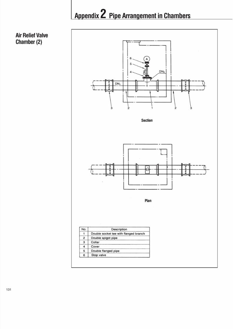
8/11/2019 Design Manual ductile iron
http://slidepdf.com/reader/full/design-manual-ductile-iron 132/138
Appendix2 Pipe Arrangement in Chambers
1
Air Relief ValveChamber (2)

8/11/2019 Design Manual ductile iron
http://slidepdf.com/reader/full/design-manual-ductile-iron 133/138
Appendix 2 Pipe Arrangement in Chambers
13
Air Relief ValveChamber (3)

8/11/2019 Design Manual ductile iron
http://slidepdf.com/reader/full/design-manual-ductile-iron 134/138
Appendix2 Pipe Arrangement in Chambers
3
Valve Chamber (1)

8/11/2019 Design Manual ductile iron
http://slidepdf.com/reader/full/design-manual-ductile-iron 135/138
Appendix 2 Pipe Arrangement in Chambers
13
Valve Chamber (2)

8/11/2019 Design Manual ductile iron
http://slidepdf.com/reader/full/design-manual-ductile-iron 136/138
Appendix2 Pipe Arrangement in Chambers
5
Wash-Out Facility

8/11/2019 Design Manual ductile iron
http://slidepdf.com/reader/full/design-manual-ductile-iron 137/138
KUBOTA CorporationPipe Export Department
Ductile Iron Pipe Division
1-3, Nihombashi-Muromachi 3-chome, Chuo-ku, Tokyo 103-8310, JAPANPhone: (81) 3-3245-3245 Fax: (81) 3-3245-3830
· Beijing Office:Rm. 1551, New Century Office Tower, No. 6,Southern Road, Capital Gym., Beijing,CHINA 100046Phone: 849-2277 Fax: 849-2280
Kubota reserves the right to change specifications or designs without notice.
Website: http://www.kubota.co.jp/ E-mail: [email protected]
Cat, No. 0084 Printed in Japan. '07.09. 0.5.KES.

8/11/2019 Design Manual ductile iron
http://slidepdf.com/reader/full/design-manual-ductile-iron 138/138
KUBOTA Corporation