design of a hybrid solar pv and fuel cell powered bldc ... · solar photo voltaic array system one...
TRANSCRIPT

International Journal Of Advancement In Engineering Technology, Management and Applied Science (IJAETMAS)
UGC APPROVED JOURNAL (Number-63082)
ISSN: 2349-3224 || www.ijaetmas.com || Volume 05 - Issue 03 || March-2018 || PP. 75-89
www.ijaetmas.com Page 75
Design of a Hybrid Solar PV and Fuel cell Powered BLDC
Motor Drive
Mr. V Satyanarayana Athmuri , Mr.M.Rajendra Prasad M-tech Scholar , Assistant Professor
Department of Electrical & Electronics Engineering,
Dadi institute of Engineering & technology, Anakapalli,
Visakhapatnam (Dt); A.P, India.
Abstract- In the current global energy scenario, importance of power generation from renewable energy sources is
increasing day by day. The major reasons for this is the limited availability of fossil fuels and environmental hazards
associated with traditional power generation methods. Renewable energy sources include Solar photovoltaic systems,
wind, low-head hydro, geothermal energy etc., Fuel cell technology is also nearing the development point where it
could start to supply a significant share of the power needs. Fuel cell can be coupled with other renewable sources
such as photovoltaic solar panels. This project intends to present a Solar PV/Fuel cell hybrid energy system fed
BLDC Motor drive. MPPT Technique is used with DC-DC converter to track maximum power from solar PV
Module. The output power generated from solar panels is intermittent in nature and varies with irradiance levels.
Hence when the solar power decreases due to low irradiance level, the load is shared by fuel cell. So here Fuel cell is
used as a backup source. In this project optimal sharing of the load power by solar PV and fuel cell is presented at
different irradiance levels. The operating characteristics of BLDC Motor are verified under different irradiance
levels. The BLDC motor has high reliability, high efficiency, high torque/inertia ratio, improved cooling, low radio
frequency interference, and noise and requires practically no maintenance. Hence now-a-days BLDC Motors are
preferred in Appliances, Automotive, Aerospace, Consumer, Medical, Industrial Automation equipment and Instrumentation.
Index Terms— Solar photovoltaic array, MPPT, Fuel cell, Brushless dc (BLDC) Motor , continuous conduction mode
(CCM), discontinuous conduction mode (DCM), Voltage Source Inverter(VSI),Electronic Commutation.
I. INTRODUCTION
Now a day’s global attention is towards non conventional energy source to satisfy the electrical load demand to the
consumer and to supply the electricity for rural areas. Solar photo voltaic array system one among the non-conventional
energy source is helpful in various applications like lightening load, aerospace applications, water pumping application etc.,
As the solar to electrical conversion efficiency is low, maximum power extraction techniques are necessary to operate the
solar photovoltaic system at maximum power operating voltage point. The simplicity of perturb and observe (P&O) MPPT
algorithm suits it for several applications [1]. The comparative analysis of different DC-DC converter for perturb and
observe MPPT algorithm is described in [2]. A fuel cell is a device that converts chemical potential energy (energy stored in
molecular bonds) into electrical energy. A PEM (Proton Exchange Membrane) cell uses hydrogen gas (H2) and oxygen gas
(O2) as fuel. The products of the reaction in the cell are water, electricity, and heat [4]. This is a big improvement over
internal combustion engines, coal burning power plants, and nuclear power plants, all of which produce harmful by-
products. The higher efficiency, reliability, maintenance free properties of BLDC motor attracts the attention to utilize it in
solar powered applications[9].
The solar photovoltaic array, Fuel cell & BLDC motor ratings are selected to suit for different atmospheric
conditions. The performance of proposed system is analyzed using MATLAB/Simulink software.
II. OPERATION OF THE PROPOSED SYSTEM
The block diagram of the Solar Photovoltaic array/fuel cell powered BLDC motor drive is shown below. It consists
of Solar PV array and fuel cell with boost converters, VSI fed BLDC motor drive. The power extracted from the PV array is
optimized to the maximum by the MPPT algorithm.

International Journal Of Advancement In Engineering Technology, Management and Applied Science (IJAETMAS)
UGC APPROVED JOURNAL (Number-63082)
ISSN: 2349-3224 || www.ijaetmas.com || Volume 05 - Issue 03 || March-2018 || PP. 75-89
www.ijaetmas.com Page 76
Fig 1: Block diagram of the proposed concept
The power required to run the BLDC motor is supplied by the solar photovoltaic array and fuel cell. The generated
voltage from the Solar PV array and fuel cell are boosted through boost converters and supplied to the voltage source
inverter (VSI). Position of the rotor is sensed by using the hall sensors and the switching states of the inverter are generated
by decoding the hall signals. As the power generated by solar PV array is intermittent in nature, here a fuel cell is taken as
back up source. In this concept different irradiance levels and temperatures are considered for solar PV array. The load
power sharing by the solar PV array and fuel cell are observed. Though there are variations in irradiance levels, temperature
the power delivered to the BLDC motor is constant and the motor characteristics are also constant at different atmospheric
conditions. The simulation results of each stage are presented. Here the Solar PV Array is the main source which will supply
power to the BLDC Motor up to its maximum power capacity by using MPPT Algorithm. Only the remaining power is supplied by the fuel cell depending on the varying conditions.
III.DESIGN OF THE PROPOSED SYSTEM
The proper designing of the system is mandatory for the efficient operation of the system under uncertain conditions.
A solar photovoltaic array of 1300 Watts Maximum power capacity and a Fuel cell of power rating 2000 Watts are designed
to run the 2000 Watts BLDC motor under standard test condition (STC). Following discussion will give in detail the modelling and designing of each part.
3.1 Modeling of the solar photovoltaic array
Basic circuit of solar photovoltaic cell is as shown in the Fig. 2. Modelling of solar photo voltaic cell is done by
using the following modelling equations [1]:
ip
Rsh
id
iph
Rsipv
Vpv
-
+
Fig 2: Mathematical equivalent circuit of solar photo voltaic cell
The current in solar Photovoltaic cell is given by:
sh
spv
s
pvspv
ophpvR
IRV
kTaN
IRVqIII
1exp --- (1)
Where,
Io Saturation current of diode
q Electric charge
Rs Series resistance of PV cell
Solar PV
Array
Boost
converter
Fuel cell Boost
converter
MPPT
VSI Fed
BLDC
Motor

International Journal Of Advancement In Engineering Technology, Management and Applied Science (IJAETMAS)
UGC APPROVED JOURNAL (Number-63082)
ISSN: 2349-3224 || www.ijaetmas.com || Volume 05 - Issue 03 || March-2018 || PP. 75-89
www.ijaetmas.com Page 77
k Boltzmann’s constant
a Ideality factor
Rsh Parallel resistance of PV cell
T actual temperature
Ns Number of cells in series
Rsh and Rs are used to represent the intrinsic series and shunt resistance of the cell respectively. Usually the value of
Rsh is very large and that of Rs is very small. In reality, it is impossible to neglect the series resistance Rs and parallel resistance Rsh because of their impact on the efficiency of PV cell.
When Rsis taken into consideration, then Id = Io exp V+IRs
a − 1 --- (2)
Io = Isc ,ref exp −Voc ,ref
a
Tc
Tc ,ref
3
exp qεG
A.k
1
Tc ,ref−
1
Tc -- (3)
Where, Isc ,ref = current when PV cell is short circuited.
Tc,ref = Temperature at STC (298K)
Due the losses in the various converter stages the power generated by the solar photo voltaic array must be higher
than the power demand of the motor. Table 1 gives the data of solar photovoltaic cell and solar photo voltaic array taken for this work.
Table -1 specifications of solar photo voltaic array
3.2 Modeling of fuel cell:
In PEM fuel cell electrochemical process starts on the anode side, where 𝐻2 molecules are brought by flow plate
channels. Anode catalyst divides hydrogen on protons H+ that travel to cathode through membrane and electrons e- that
travel to cathode over external electrical circuit. At the cathode hydrogen protons H+ and electrons e- combine with oxygen
O2 by use of catalyst, to form water H2O and heat [4]. Described reactions can be expressed using equations:
𝐻2--->2𝐻+ +2𝑒_ (Anode) --- (4)
𝟏
𝟐 𝐎𝟐 +2𝐇++2𝐞−_--->𝐇𝟐O (Cathode) --- (5)
Amount of chemical energy released in these reactions depends on hydrogen pressure, oxygen pressure and fuel cell temperature. Using change in Gibbs free energy, this amount can be expressed as:
∆𝐠𝒇=∆𝒈𝒇𝟎-R𝑻𝒇𝒄[ln(𝑷𝑯𝟐)+
𝟏
𝟐ln(𝑷𝑶𝟐)] --- (6)
where ∆𝒈𝒇𝟎 is change in Gibbs free energy at standard pressure, R universal gas constant, 𝑻𝒇𝒄 PEM temperature and
𝒑𝑶𝟐 and 𝑷𝑯𝟐are gas pressures. Because electrical work done by fuel cell is equivalent to released chemical energy, value of
open circuit fuel cell voltage E meets equation:
E= - ∆𝑔𝑓
2𝐹, --- (7)

International Journal Of Advancement In Engineering Technology, Management and Applied Science (IJAETMAS)
UGC APPROVED JOURNAL (Number-63082)
ISSN: 2349-3224 || www.ijaetmas.com || Volume 05 - Issue 03 || March-2018 || PP. 75-89
www.ijaetmas.com Page 78
where F is Faraday's constant. To attain actual cell voltage (on electrical couplings) 𝑣𝑓𝑐 , voltage drops caused by
activation, concentration and ohmic losses have to be deducted from open circuit voltage. Cathode and anode activation
losses are result of breaking and forming electron-proton chemical bonds, and parasitic electrochemical reactions caused
from hydrogen proton migration through membrane at zero current. Their voltage drop was calculated using formula:
𝑣𝑎𝑐𝑡 =𝑣0+𝑣𝑎 (1-𝑒−𝑐1𝑖 ) --- (8)
where activation voltage drop at zero current density 𝑣0 depends on fuel cell temperature, cathode pressure and water
saturation pressure 𝑣0=(𝑇𝑓𝑐 ,𝑝𝑐𝑎 ,𝑃𝑠𝑎𝑡 ) . Voltage drop va inserts in correlation with current density i and depends on fuel cell
temperature, oxygen pressure and water saturation pressure 𝑣𝑎= (𝑇𝑓𝑐 ,𝑝𝑜2,𝑃𝑠𝑎𝑡 ) and 𝑐1 is activation voltage constant.
Concentration losses are caused by drop in reactant concentration due to dynamic flow problems between water and
oxygen on cathode side, and also electroosmotic water drag that occurs when protons travel through membrane. Voltage
drop caused by these losses is described with equation:
𝑣𝑐𝑜𝑛𝑐 =i[𝑐2
𝑖
𝑖𝑚𝑎𝑥
]𝑐2 --- (9)
where imax represents current density that causes steep PEM voltage drop, parameter 𝑐2is function of temperature,
oxygen pressure and water saturation pressure, 𝑐2=(𝑇𝑓𝑐 ,𝑃𝑠𝑎𝑡 ) and 𝑐3is concentration voltage constant.
Ohmic losses are derived from membrane resistance 𝑅𝑜𝑚 whose value depends of membrane thickness 𝑡𝑚 , fuel cell
temperature 𝑇𝑓𝑐 and membrane water content degree 𝜆𝑚
𝑅𝑜𝑚=𝑡𝑚
𝜎𝑚, --- (10)
𝜎𝑚=(𝑏11𝜆 𝑚 -𝑏12)exp[𝑏2(1
303-
1
𝑇𝑓𝑡)] --- (11)
Value 𝜎𝑚 in (8) represents specific membrane conductivity and 𝑏11 , 𝑏12 and 𝑏2 are membrane conductivity constants.
Voltage drop of ohmic losses is expressed as:
𝑣𝑜𝑚=𝑅𝑜𝑚 i --- (12)
Using calculated voltage drops and open circuit cell voltage, value 𝑣𝑓𝑐 of actual cell voltage in static condition can be
attained using equation:
𝑣𝑓𝑐 =E-𝑣𝑎𝑐𝑡 -𝑣𝑐𝑜𝑛𝑐 -𝑣𝑜𝑚 --- (13)
Dynamic electric model was gained by implementing influence of parasitic capacitance C in previously described
static model. Fuel cell equivalent electric circuit with capacitance C
is shown in figure. On it 𝑅𝑎𝑐𝑡 is resistance that corresponds to
activation losses, and 𝑅𝑐𝑜𝑛𝑐 resistance that represents concentration losses:
𝑅𝑎𝑐𝑡 =𝑣𝑎𝑐𝑡
𝑖=
𝑣0+𝑣𝑎 (1−𝑒−𝑐2 𝑖)
𝑖 --- (14)
𝑅𝑐𝑜𝑛𝑐 =𝑣𝑐𝑜𝑛𝑐
𝑖=(𝑐2
𝑖
𝑖𝑚𝑎𝑥)𝑐2 --- (15)
Fig 3 : fuel cell electric equivalent circuit
Based on electrical circuit from figure 4.3, following equations that show current-voltage relations can be written
𝐶𝑑𝑣𝑐
𝑑𝑡+
𝑣𝑐
𝑅𝑎𝑐𝑡 +𝑅𝑐𝑜𝑛𝑐
=i, --- (16)

International Journal Of Advancement In Engineering Technology, Management and Applied Science (IJAETMAS)
UGC APPROVED JOURNAL (Number-63082)
ISSN: 2349-3224 || www.ijaetmas.com || Volume 05 - Issue 03 || March-2018 || PP. 75-89
www.ijaetmas.com Page 79
𝑣𝑓𝑡=E-𝑣𝑐-i𝑅𝑜𝑚 . --- (17)
The solar PV and Fuel cell hybrid system is connected to the voltage source inverter through DC-DC converters. In
the solar PV Array a boost converter is used to implement MPPT algorithm. Output voltage of the boost converter is Vo = 1
1−𝐷 𝑉𝑑 where 𝑉𝑑 is the input voltage and D is the duty ratio. Here the output voltage after boosting is 430 Volts. The pulse
generated from the MPPT algorithm is given to the boost converter in solar PV system. The output voltage from the boost
converter of fuel cell is 430V. The output of these boost converters is given as the input to the voltage source inverter VSI
fed BLDC Motor.
3.3 BLDC Motor:
A BLDC motor is a permanent magnet synchronous that uses position detectors and an inverter to control the
armature currents. The BLDC motor is sometimes referred to as an inside out dc motor because its armature is in the stator
and the magnets are on the rotor and its operating characteristics resemble those of a dc motor. Instead of using a mechanical
commutator as in the conventional dc motor, the BLDC motor employs electronic commutation which makes it a virtually maintenance free motor [9].
The electromagnetic torque of a BLDC Motor is given by
𝑇𝑒= 2𝑒𝑝 𝑖𝑝
𝜔𝑚 --- (18)
Where 𝑒𝑝= phase back emf in volts and 𝑖𝑚𝑝 = phase current in amperes
The output voltage frequency of VSI with respect to the rated speed of the motor is
ωrated = 2πfrated = 2πNrated P
120 --- (19)
Table 2: SPECIFICATIONS OF BLDC MOTOR
S. No Parameter Value
1. Rated Power(P) 2kW
2. Speed(N) 3500 rpm
3. Rated DC voltage 350
4. No. of poles 4
5. Moment of inertia 8 Kg.cm2
6. Voltage constant, Ke 78 V/krpm
7. Torque constant, Kt 0.74 Nm/A
8. Phase resistance, Rs 4Ω
9. Phase inductor, Ls 9.5Mh
10. Rated Torque(T) 4.5N-m
IV.CONTROL OF THE PROPOSED SYSTEM
In the proposed work three controlling stages are applied, one to generate pulses for DC-DC converter to track the
maximum power point through MPPT algorithm for Solar PV Array. Second is to generate power from fuel cell. Here the
Solar power is extracted to the maximum point and during low irradiance levels the deficit power is shared by fuel cell.
Third one is to generate firing pulses to VSI through hall sensors and to run BLDC Motor.
International Journal Of Advancement In Engineering Technology, Management and Applied Science (IJAETMAS)
UGC APPROVED JOURNAL (Number-63082)
ISSN: 2349-3224 || www.ijaetmas.com || Volume 05 - Issue 03 || March-2018 || PP. 75-89
www.ijaetmas.com Page 80
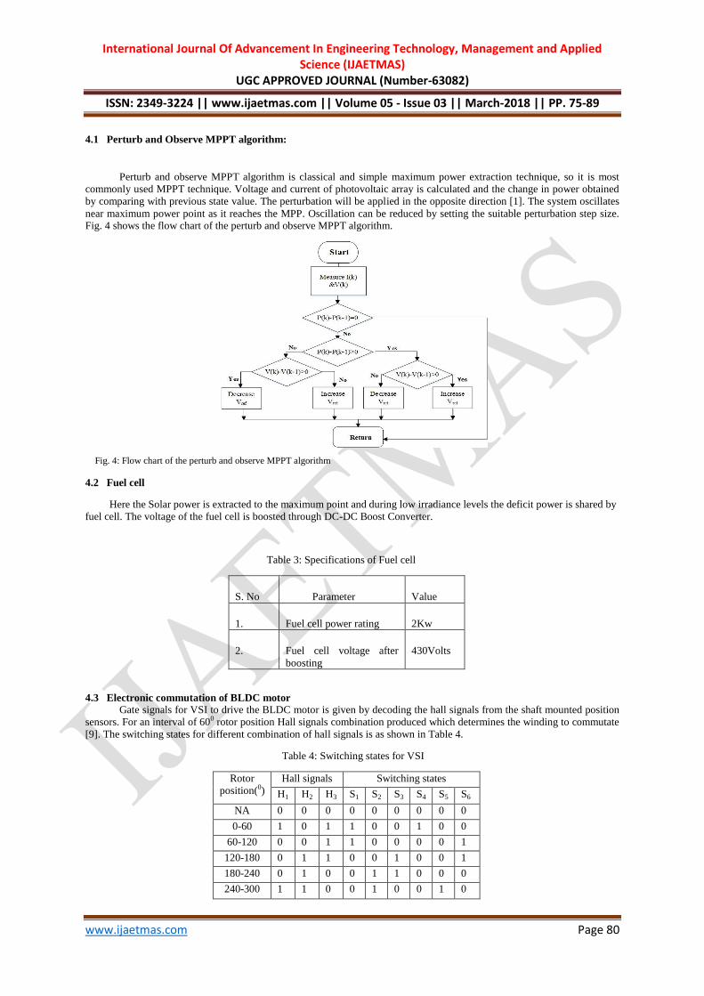
4.1 Perturb and Observe MPPT algorithm:
Perturb and observe MPPT algorithm is classical and simple maximum power extraction technique, so it is most
commonly used MPPT technique. Voltage and current of photovoltaic array is calculated and the change in power obtained
by comparing with previous state value. The perturbation will be applied in the opposite direction [1]. The system oscillates
near maximum power point as it reaches the MPP. Oscillation can be reduced by setting the suitable perturbation step size. Fig. 4 shows the flow chart of the perturb and observe MPPT algorithm.
Fig. 4: Flow chart of the perturb and observe MPPT algorithm
4.2 Fuel cell
Here the Solar power is extracted to the maximum point and during low irradiance levels the deficit power is shared by
fuel cell. The voltage of the fuel cell is boosted through DC-DC Boost Converter.
Table 3: Specifications of Fuel cell
1 S. No 2 Parameter 3 Value
4 1. 5 Fuel cell power rating 6 2Kw
7 2. 8 Fuel cell voltage after
boosting
9 430Volts
4.3 Electronic commutation of BLDC motor
Gate signals for VSI to drive the BLDC motor is given by decoding the hall signals from the shaft mounted position
sensors. For an interval of 600 rotor position Hall signals combination produced which determines the winding to commutate
[9]. The switching states for different combination of hall signals is as shown in Table 4.
Table 4: Switching states for VSI
Rotor
position(0)
Hall signals Switching states
H1 H2 H3 S1 S2 S3 S4 S5 S6
NA 0 0 0 0 0 0 0 0 0
0-60 1 0 1 1 0 0 1 0 0
60-120 0 0 1 1 0 0 0 0 1
120-180 0 1 1 0 0 1 0 0 1
180-240 0 1 0 0 1 1 0 0 0
240-300 1 1 0 0 1 0 0 1 0

International Journal Of Advancement In Engineering Technology, Management and Applied Science (IJAETMAS)
UGC APPROVED JOURNAL (Number-63082)
ISSN: 2349-3224 || www.ijaetmas.com || Volume 05 - Issue 03 || March-2018 || PP. 75-89
www.ijaetmas.com Page 81
300-360 1 0 0 0 0 0 1 1 0
NA 1 1 1 0 0 0 0 0 0
VI. SIMULATION RESULTS AND DISCUSSIONS
Fig 5: MATLAB Simulink model of the proposed concept
Case-1: Consider a step input with irradiance varying from 1000 W/𝑚2 to 100 W/𝑚2 at T=250C, 𝑁𝑠=182, 𝑁𝑝=6
1) Solar PV current (Ipv):
Fig 6: Solar PV Current at G varying from 1000W/𝑚2 to 100 W/𝑚2 (Step input of G)
2) Fuel cell current (If):

International Journal Of Advancement In Engineering Technology, Management and Applied Science (IJAETMAS)
UGC APPROVED JOURNAL (Number-63082)
ISSN: 2349-3224 || www.ijaetmas.com || Volume 05 - Issue 03 || March-2018 || PP. 75-89
www.ijaetmas.com Page 82
Fig 7: Fuel cell Current at G varying from 1000W/𝑚2 to 100 W/𝑚2 (Step input of G)
Analysis of source currents: When the irradiance (G) decreases from 1000 W/𝑚2 to 100 W/m2
𝐼𝑝𝑣 decreases from 3 amperes to 0.2 amperes.
If increases from 1.5 amperes to 4.3 amperes.
Hence DC Bus Current remains constant at 4.5 Amperes.
3) Load power sharing by the 2 sources:
Fig 8: Load power sharing by the 2 sources at G varying from 1000W/𝑚2 to 100 W/𝑚2 (Step input of G)
Analysis of source powers: Solar PV power decreases from 1200 watts to 100 watts when the irradiance decreases from
1000 W/𝑚2 to 100 W/𝑚2and at the same time Fuel cell power increases from 800 watts to 1900 watts and hence the total
power remains constant at 2000 watts.
Case-2: Consider a constant irradiance level of 1000 W/𝑚2 at T=250C, 𝑁𝑠=182, 𝑁𝑝=6
1) Solar PV Current (Ipv):
Fig 9: Solar PV Current at a constant G of 1000W/𝑚2
2) Fuel cell current (If):
Fig 10: Fuel cell Current at a constant G of 1000 W/𝑚2

International Journal Of Advancement In Engineering Technology, Management and Applied Science (IJAETMAS)
UGC APPROVED JOURNAL (Number-63082)
ISSN: 2349-3224 || www.ijaetmas.com || Volume 05 - Issue 03 || March-2018 || PP. 75-89
www.ijaetmas.com Page 83
Analysis of source currents:
At constant G=1000 W/𝑚2
𝐼𝑝𝑣 = 4 amperes and
If at 0.5 amperes hence the
DC bus current remains=4.5 Amperes
3) Load power sharing by the 2 sources:
Fig 11: Load power sharing by the 2 sources at a constant G of 1000 W/𝑚2
Analysis of source powers:
Solar PV power remains constant at 1300 watts at a constant irradiance of 1000 W/𝑚2 and at the same time Fuel cell power is also at a constant value of 700 watts and hence the total power remains constant at 2000 watts.
Case-3: Consider the case when irradiance level is very low say 100 W/𝑚2 at T=250C, 𝑁𝑠=182, 𝑁𝑝=6.
1) Solar PV Current (Ipv):
Fig 12: Solar PV Current at constant low G= 100W/𝑚2
2) Fuel cell current (If):
Fig 13: Fuel cell Current at a constant low irradiation of G of 100W/𝑚2
Analysis of source currents:
At G= 100 W/𝑚2
𝐼𝑝𝑣= 0.2 Amperes and at the same time
𝐼𝑓= 4.3 Amperes and hence the
DC bus current= constant at 4.5 Amperes.
3) Load power sharing by the 2 sources

International Journal Of Advancement In Engineering Technology, Management and Applied Science (IJAETMAS)
UGC APPROVED JOURNAL (Number-63082)
ISSN: 2349-3224 || www.ijaetmas.com || Volume 05 - Issue 03 || March-2018 || PP. 75-89
www.ijaetmas.com Page 84
Fig 14: Load power sharing by the 2 sources at a constant low irradiation of G of 100W/𝑚2
Analysis of source powers: At G=100 W/𝑚2 Solar PV power=100 watts and
Fuel cell power=1900 watts and hence the total power remains constant at 2000 watts. Here fuel cell plays major role in load power sharing.
Case-4: Consider the case when fuel input to fuel cell is reduced i.e., its reference power is reduced and solar panel is
operated at a constant irradiance level of 1000 W/𝑚2 at T=250C, 𝑁𝑠=182, 𝑁𝑝=6
1) Solar PV current (Ipv):
Fig 15: Solar PV current at G=1000 W/𝑚2 With reduced fuel cell input
2) Fuel cell current (If):
Fig 16: Fuel cell current at G=1000 W/𝑚2 With reduced fuel cell input
Analysis of Source currents:
At G=1000 W/𝑚2 and reduced fuel cell input
Ipv=3.3 Amperes and at the same time
If=1.2 Amperes when the fuel input is reduced and hence the DC bus current=4.5 Amperes.
3) Load power sharing by the 2 sources
Fig 17: Load power sharing by the 2 sources at G=1000 W/𝑚2 with reduced fuel input

International Journal Of Advancement In Engineering Technology, Management and Applied Science (IJAETMAS)
UGC APPROVED JOURNAL (Number-63082)
ISSN: 2349-3224 || www.ijaetmas.com || Volume 05 - Issue 03 || March-2018 || PP. 75-89
www.ijaetmas.com Page 85
Analysis of source powers: It can be clearly observed that Solar PV power remains constant at 1300 watts at a constant
irradiance of 1000 W/𝑚2 and at the same time Fuel cell power is also at a constant value of 700 watts when the fuel input is
reduced and hence the total power remains constant at 2000 watts.
Case-5: Consider a step input with irradiance varying from 1000 W/𝑚2 to 100 W/𝑚2 at T=180C, 𝑁𝑠=182, 𝑁𝑝=6 (varying
temperature)
1) Solar PV current (Ipv):
Fig 18: Solar PV Current at G varying from 1000W/𝑚2 to 100 W/𝑚2 (G=Step input), T=180C
2) Fuel cell current (If):
Fig 19: Fuel cell Current at G varying from 1000W/𝑚2 to 100 W/𝑚2 (Step input of G), T=180C
Analysis of source currents: When the irradiance decreases from 1000 W/𝑚2 to 100 W/𝑚2 at new temperature T=180C
Ipv=decreases from 3.5amperes to 0.3 amperes and
If=increases from 1 Ampere to 4.2 Amperes and hence the DC bus current remains constant at 4.5 Amperes.
3) Load power shared by the 2 sources:
Analysis of source powers: It can be clearly observed that Solar PV power decreases from 1200 watts to 200 watts when
the irradiance decreases from 1000 W/𝑚2 to 100 W/𝑚2 at a new temperature T= 180C and at the same time Fuel cell power
increases from 800 watts to 1800 watts and hence the total power remains constant at 2000 watts.
Fig 20: Load power sharing by 2 sources at G varying from 1000W/𝑚2 to 100 W/𝑚2 (Step input of G), T=180C
From the MATLAB simulink results of the proposed project it is clear that whatever may be the irradiance levels to
the solar PV and though the fuel input to the fuel cell is varied, the Solar PV and fuel cell will share the load power and a constant power output is maintained which is to be fed to the BLDC Motor.
The following simulink results prove that though the irradiance levels to the solar PV Array and fuel input to the fuel cell are varied, a constant power output is maintained which is to be fed to the BLDC Motor.
1) Total DC Bus voltage

International Journal Of Advancement In Engineering Technology, Management and Applied Science (IJAETMAS)
UGC APPROVED JOURNAL (Number-63082)
ISSN: 2349-3224 || www.ijaetmas.com || Volume 05 - Issue 03 || March-2018 || PP. 75-89
www.ijaetmas.com Page 86
Fig 21: Total DC Bus voltage
Here DC Bus voltage= 430 volts
2) Total DC Bus Current
Fig 22: Total DC Bus Current
Here DC Bus Current= 4.5 Amperes
3) Combined Solar and Fuel power which is fed to BLDC Motor in watts
Fig 23: Total DC Bus power
Here total DC bus power= 2000 watts i.e., 2kW
4) AC step input voltage to be fed to BLDC Motor
Fig 24: AC step voltage to be applied to DC Motor
Here AC Step input voltage to be fed to BLDC Motor= 430 Volts
5) Rotor speed of BLDC Motor in RPM:
Fig 25: Rotor speed (N) of BLDC Motor in RPM

International Journal Of Advancement In Engineering Technology, Management and Applied Science (IJAETMAS)
UGC APPROVED JOURNAL (Number-63082)
ISSN: 2349-3224 || www.ijaetmas.com || Volume 05 - Issue 03 || March-2018 || PP. 75-89
www.ijaetmas.com Page 87
Here Rotor speed of BLDC Motor= 3500 RPM
6) Torque (N-M) of BLDC Motor:
Fig 26: Electromagnetic Torque (N-m) of BLDC Motor
Here Electromagnetic Torque of BLDC Motor= 4.5 N-m
7) Back Emf (Volts) of BLDC Motor:
Fig 27: Back EMF of BLDC Motor
Here Back Emf of BLDC Motor= 145 Volts
8) At STC i.e., at T=250c & G(Irradiance)=1000 W/𝑚2 PV array characteristic curve (Current Vs Voltage) is
Fig 28: Solar PV Array I Vs V characteristic
9) Stator Currents of BLDC Motor:

International Journal Of Advancement In Engineering Technology, Management and Applied Science (IJAETMAS)
UGC APPROVED JOURNAL (Number-63082)
ISSN: 2349-3224 || www.ijaetmas.com || Volume 05 - Issue 03 || March-2018 || PP. 75-89
www.ijaetmas.com Page 88
Fig 29: Stator currents of BLDC Motor
Here Magnitude of stator current=7.7 Amperes
10) At STC i.e., at T=250c & G(Irradiance)=1000 W/𝑚2 PV array characteristic curve (Current Vs Voltage) is
Fig 30: Solar PV Array P Vs V characteristic
Table 4: Summarized table of simulation results of the proposed concept
VII. Conclusion
The proposed solar PV/Fuel cell powered BLDC Motor drive has been designed, modelled and simulated in the
MATLAB/Simulink. The performance of proposed drive was observed from BLDC motor stator current, speed and torque
curves. The performance of the motor speed and torque was found satisfactory for constant irradiance condition and also for
variable irradiance conditions,temperatures along with reduced fuel input also. Based on the simulation results, the proposed
concept is suitable and compatible for the combination of solar PV and fuel cell powered BLDC Drive at variable weather conditions.
REFERENCES
[1] Biju K and Rijil Ramchand, “Modeling and simulation of a novel solar PV/ battery hybrid energy system with a single phase five level inverter”, 978-1-4799-1823-2/15/$31.00 ©2015 IEEE.
[2] Sachin Jain and Vivek Agarwal, “A single stage Grid connected inverter topology for solar PV systems with Maximum Power Point Tracking”, IEEE Transactions on Power Electronics, vol22, issue.5, Publication year: 2007.
[3] Standaert, K. Hemmes, and N. Woudstra, “Analytical fuel cell modeling,” Journal of Power Sources, vol. 63, pp. 221– 234, 1996.
[4] M. Petrinic and Z. Jakopovic, “Modeling and simulation of PEM fuel cell – power converter system”, Fuel cell

International Journal Of Advancement In Engineering Technology, Management and Applied Science (IJAETMAS)
UGC APPROVED JOURNAL (Number-63082)
ISSN: 2349-3224 || www.ijaetmas.com || Volume 05 - Issue 03 || March-2018 || PP. 75-89
www.ijaetmas.com Page 89
technology vol., 85, no. 7, pp. 1477-1484, May 2012.
[5] Valeria Boscaino, Giuseppe Capponi, Patrizia Livreri, Filippo Marino, “Fuel Cell Modelling for Power Supply Systems Design”, 978-1-4244-2551-8/08/$20.00 ©2008 IEEE
[6] W. Choi, P.N. Enjeti, and J.W. Howze, “Development of an equivalent circuit model of a feul cell to evaluate the effects of inverter ripple current,” APEC ’04, vol. 1, pp. 355 – 361, February, 2004.
[7] B.Arundhati, S.Murali, M.V.G.Prasad, “Solar powered BLDC Motor Drive using Zeta Converter” in International
Journal of pure and Applied Mathematics, vol. 114, No 8 2017,81-91.
[8] Vinod Kr Singh Patel, A.K.Pandey, “Modeling and Simulation of Brushless DC Motor Using PWM Control Technique”,
IJERA , Vol. 3, Issue 3, May-Jun 2013, pp.612620.
[9] Rajan Kumar and Bhim Singh, “BLDC Motor-Driven Solar PV Array-Fed Water Pumping System Employing Zeta Converter”, IEEE transactions on industry applications, vol. 52, no. 3, may/june 2016.
V Satyanarayana Athmuri received B.Tech Degree in Electrical and Electronics Engineering from Vignans institute of
information Technology, Duvvada, Visakhapatnam, India in 2009 and currently pursuing M.Tech in Dadi Institute of
Engineering and Technology, Anakapalli, Visakhapatnam, India. His fields of interest include Power Electronics and
Electrical Machines.
M. Rajendra Prasad received his M.tech degree from Lakkireddy and Balireddy college of engineering, Vijiawada,
Andhra pradesh, India .He is working as Assistant professor in Dadi Institute of Engineering and Technology, since June
2016. His areas of interests are Distributed Energy Systems, Power electronics, Control systems and Power flow in Micro
grids.