design of a non-contact infrared thermometer
TRANSCRIPT

DESIGN OF A NON-CONTACT INFRARED THERMOMETER
Guangli Long
School of Physics and Telecommunication Engineering
Shaanxi University of Technology, Postcode 723001
Hanzhong, China
Emails: [email protected]
Submitted: Jan. 15, 2016 Accepted: Mar. 20, 2016 Published: June 1, 2016
Abstract- In order to realize the human body temperature fast and non-contact measurement, an
infrared thermometer is designed. The infrared human body temperature sensor is mainly used to
convert the human body's infrared into voltage signal, an operational amplifier to amplify the signal,
filter circuit to filter the signal, the analog signal into digital signal by the A/D conversion circuit, data
processing by the MCU, LCD display and voice reporting body temperature and time, so the human
body non-contact measurement is realized. The experimental results show that: the device can realize
the temperature and time of acquisition, the measurement error is not more than 0.5℃, voice broadcast
and liquid crystal display the temperature and time, overrun alarm and other functions.
Index terms: infrared temperature sensor, MCU, LCD, voice broadcast.
INTERNATIONAL JOURNAL ON SMART SENSING AND INTELLIGENT SYSTEMS VOL. 9, NO. 2, JUNE 2016
1110

Ⅰ. INTRODUCTION
In daily life, the measurement of body temperature is a basic way to determine the normal
life of the human body. Although the price of traditional mercury thermometers is cheap , the
existing problems are as follows when it is used: Mercury thermometer must contact with the
human body , and temperature measurement process need lasted 5 to 10 minutes, because infants
is active, let parents become very headache for infant body temperature; And in the number of
temperature meter reading, easy to read wrong due to external light and other factors; Mercury
thermometer is easy to rupture when heated or stored improperly, It can lead to mercury
poisoning due to human body exposure to mercury [1]
. Infrared temperature sensor is used for
measuring temperature, The measurement trouble of the traditional contact thermometer is
avoided. It is especially suitable for infants and young children to measure the body
temperature ,and the measured temperature is displayed by the liquid crystal display module, it is
accurate, and it has the function of voice broadcast, it is convenient for the people with poor
eyesight.
Ⅱ. PRINCIPLE OF INFRARED TEMPERATURE MEASUREMENT
In nature, when the temperature of the object is higher than the absolute zero (-273.15℃),
Electromagnetic waves will continue to radiate around due to the thermal motion of molecules.
the radiation of the electromagnetic wave contains the infrared radiation of 0.75 ~100μm, the
radiation energy density and the temperature of the object are in accordance with the law of
radiation[2-3]
:
)( 4
1
4
2 TTA (1)
In the formula: A is a radiation degree, the unit is W/m3; αis the Stephen Pozman constant, α
=5.67×10⁻⁸
W/(m2﹒K
4);βis the radiation rate; T2 is the absolute temperature of the object, the
unit is K; T1 is the ambient temperature, the unit is K.
The numerical value of the radiation rate is 0~1.0, which indicates the ability of the
radiation electromagnetic wave. All real objects (including the surface of the human body ), β
values are less than 1.0. The main radiation infrared wavelength of the human body is 9 ~ 10μ
Guangli Long, DESIGN OF A NON-CONTACT INFRARED THERMOMETER
1111

m, human body surface temperature can be accurately measured by measuring the body's own
radiation infrared energy. Because the light in the range of 9 to 10μm is not absorbed by air, the
surface temperature of the human body can be determined by infrared energy.
The relationship between the temperature of radiator and detection voltage can be derived
by the Planck formula, that is:
4
2
4
2 TTU (2)
In the formula: ρ=μγβα,T2 is the absolute temperature of the object to be measured, μ is the
sensitivity of the detector, γ is constant which is related with the atmospheric attenuation
distance, β is radiation rate,α is the Stefan Boltzmann constant.
According to the formula (2), the output signal of the detector and the target temperature are
nonlinear, and the T24 is proportional to U,Therefore, the surface temperature of the object should
be linearized, and the radiation rate can be corrected, so that the real temperature can be obtained,
Correction formula is:
4
02
T
TT
(3)
In the formula::T0 is the surface temperature (radiant temperature); β(T) is the radiation rate,
it’s value is 0.1 ~ 0.9.
The real temperature is higher than the ambient temperature after the radiation rate
correction due to the influence of the radiation signal, so the ambient temperature is also
compensated, that is: The temperature of the ambient temperature plus the actual temperature is
the actual temperature of the measured object[4-6]
.
Ⅲ. DESIGN OF THE HARDWARE
a. Design of hardware circuit diagram
The hardware circuit diagram of the non-contact infrared thermometer is shown in Figure 1.
Infrared receiving signal emitted by the human body is converted to voltage by the infrared
sensor module, the signal is amplified by operational amplifier, amplified signal is filtered by the
filter circuit, analog signal is converted to digital signal by the analog to digital conversion circuit
,and the command signal is input the MCU processed .and the clock signal will be into the
INTERNATIONAL JOURNAL ON SMART SENSING AND INTELLIGENT SYSTEMS VOL. 9, NO. 2, JUNE 2016
1112

microcontroller by the clock circuit, the results of the software to run is displayed through the
LCD1602, Voice module playing sound, buzzer alarm when the results of the measurement to
reach the warning value.
MCU
Infrared
temperature
measurement
sensor module
LCD display
Keyboard
Buzzer
Voice
recording
module
Power
amplifie
r module
SpeakerClock circuit
Fig. 1 The hardware circuit diagram of the non-contact infrared thermometer
b. Design of minimum system of MCU
STC89C52 MCU [7]
is selected, Design of the MCU minimum system[8-9]
as shown in Figure
2, MCU minimum system consists of reset circuit, clock circuit and MCU STC89C52.
1
23
4
5
6
7
8
9
10
11
12
13
14
15
16
17
18
19
20
1
2
40
39
38
37
36
35
34
33
32
31
29
28
27
26
25
24
23
22
21
30
ST
C89
C52
P1.0
P1.1
P1.2
P1.3
P1.4
P1.5
P1.6
P1.7RST
(RX0) P3.0
(TX0) P3.1
(INT0) P3.2
(INT1) P3.3
(T0) P3.4
(T1) P3.5
(WR) P3.6
(RD) P3.7XTAL2
XTAL1
GND
VCC
P0.0
P0.1
P0.2
P0.3
P0.4
P0.5
P0.6
P0.7EA/VPP
ALE/PROG
PSEN
P2.7 (A15)
P2.6 (A14)
P2.5 (A13)
P2.4 (A12)
P2.3 (A11)
P2.2 (A10)
P2.1 (A9)
P2.0 (A8)
K1
11.0592M
30pf
30pf
10μF
Vcc
Vcc
10K
Vcc
Fig. 2 MCU minimum system
Guangli Long, DESIGN OF A NON-CONTACT INFRARED THERMOMETER
1113

Reset circuit of MCU is generally divided into three kinds: manual reset, automatic power
on reset, manual and automatic reset. The power on reset through a capacitor and a resistor in
series to achieve, when the electric MCU system, capacitor for charging takes time, so keep a
high level for a period of time at the RST end, MCU completed reset after the capacitor charging
because of the effects of RST end resistance recovery low level. The manual reset is through a
button and a resistor in series, when the button is pressed, resulting in high RST end, when the
button is released, RST terminal becomes low, the MCU complete reduction. System reset circuit
with manual and automatic reset mode, it not only has the automatic power on reset function, but
also can through the small button to manually reset.
MCU clock source is provided in two ways, one is the external clock source to provide the
clock for the microcontroller, another is the internal clock chip. The internal clock mode is
selected in the system clock circuit, an external crystal oscillator is connected between the MCU
XTAL1 and XTAL2 pins, 11.0592MHz crystal was selected, the internal clock frequency is
11.0592MHz, two 30pF ceramic capacitors were chosen in order to help the crystal oscillator,
which is connected in series with the crystal legs.
STC89C52 MCU is a 8 bit CMOS and low-power microcontroller, it is compatible with 51
series microcontroller, its interior has 8k bytes FLASH program storage space and 256 bytes of
internal RAM, 32 programmable I/O interface, three 16 bit timer / counter, full duplex UART
serial interface, built-in the watchdog timer, double data pointer.
c. Infrared sensor temperature measurement module
TN901 infrared detector is a non-contact infrared sensor temperature measurement module,
which is produced by the Ling Yang company. The measurement accuracy is high, the response
speed is fast, the measurement range is wide, the environment temperature and the target
temperature can be measured simultaneously.
IR-SoC(Infrared System on chip)technology and batch calibration technology are adopted
by TN901 infrared detector, so that the product size and cost may be reached to the minimum,
battery voltage is not more than 9V, which contains a temperature sensor, it can be directly
converted into digital quantity, its resolution is 9,10, 11, 12bit, factory default setting 12bit,
resolution can be programmed, temperature conversion accuracy can be configured by setting
internal registers. The conversion accuracy of the temperature is four kinds, thay are 0.5℃、
0.25℃、0.125℃、0.0625℃. When the format of converted temperature is 16 bit, it is stored in
INTERNATIONAL JOURNAL ON SMART SENSING AND INTELLIGENT SYSTEMS VOL. 9, NO. 2, JUNE 2016
1114
the scratchpad RAM, the temperature information can be read from 1-Wire interface by reading
scratchpad RAM command (BEH). Its format of transmission data is high bit in behind and low
bit in front[10-11]
. Parasitic power supply mode is adopted by TN901, that is energy can be
obtained from the single BUS, it is stored in the internal capacitance, the energy is consumed in
the signal line at a low level and added in the signal line for high power. 3 ~ 5.5V external power
supply can also be used by TN901. Therefore TN901 has two ways to connect with the
microcontroller, one is the external power supply, it is connected to the Vcc, the GND of TN901
is connected to the GND of the microcontroller, I/O pin of TN901 is connected to the I/O pin of
microcontroller; Another is the internal parasitic power supply, that is, the GND and UDD of
TN901 are connected to the GND, I/O pin of TN901 is connected to the I/O pin of
microcontroller. Both the use of external power supply or internal power, the 5kΩ pull resistors is
connected with the I/O port. Temperature compensation technology is used in the TN901 infrared
thermometer module, the ambient temperature can be accurately measured by The thermal
reactor MEMS. Since the SoC technology is applied by the infrared temperature module TN901,
the integration and cost ratio is improved, the heat attack can reach 10℃.
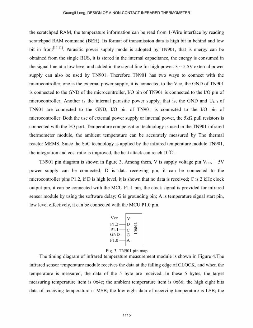
TN901 pin diagram is shown in figure 3. Among them, V is supply voltage pin VCC, + 5V
power supply can be connected; D is data receiving pin, it can be connected to the
microcontroller pins P1.2, if D is high level, it is shown that no data is received; C is 2 kHz clock
output pin, it can be connected with the MCU P1.1 pin, the clock signal is provided for infrared
sensor module by using the software delay; G is grounding pin; A is temperature signal start pin,
low level effectively, it can be connected with the MCU P1.0 pin.
V
D
CG
A
P1.2
P1.1
P1.0
TN
901
Vcc
GND
Fig. 3 TN901 pin map
The timing diagram of infrared temperature measurement module is shown in Figure 4.The
infrared sensor temperature module receives the data at the falling edge of CLOCK, and when the
temperature is measured, the data of the 5 byte are received. In these 5 bytes, the target
measuring temperature item is 0x4c; the ambient temperature item is 0x66; the high eight bits
data of receiving temperature is MSB; the low eight data of receiving temperature is LSB; the
Guangli Long, DESIGN OF A NON-CONTACT INFRARED THERMOMETER
1115

verification code is Sum. When the receiving data is correct, Sum=Item+MSB+LSB; when the
end of the symbol CR is 0x0dH, the reception of a temperature data is completed.
DATA
CLOCK
500us
Byte 0
Item MSB CRLSB Sum Message fomat
DATA DATA
20us
>0.1s
Fig. 4 The timing diagram of infrared temperature measurement module
When the checking and testing item is 0x66H or 0x4cH, whether the measurement is the
ambient temperature or the target temperature, when CR is 0x0dH, the formula for calculating the
temperature is the same, that is:
Ambient temperature/target temperature = Temp/16 - 273.15 (4)
Among them: When the decimal Temp is converted to hexadecimal, LSB is low eight bits, MSB
is high eight bits; For example, when the LSB is 0x6bH, MSB is 0x13H, the hexadecimal Temp
is 0x136bH, the decimal is 4971, the measured temperature value is:4971/16-273.15=37.5375℃
。
d. Design of voice broadcast circuit
The design of voice broadcast circuit is shown in Figure 5.
SYN6288 speech synthesis chip is used in voice broadcast circuit, the chip SMT packaging,
which has a simple hardware interface, low power consumption, high performance price ratio,
The text data to be synthesized is received through the asynchronous serial communication mode,
which is converted from the text to speech. The data of SYN6288 voice chip is transmitted with a
microprocessor or PC through a set of full duplex asynchronous communication interface.
Buttons S1 and S2 and S3 can be applied in the circuit and control the recording and playback, S1
is the record button, S2 is the playback button, falling edge trigger, S3 is level controlling button.
INTERNATIONAL JOURNAL ON SMART SENSING AND INTELLIGENT SYSTEMS VOL. 9, NO. 2, JUNE 2016
1116

When the 25 pin of SYN6288 is high level, it shows that the recording beyond the time limit
(memory overflow) or the recording ended or playback ended. To segment the recording, speech
information and segmented address of the control table can be listed in advance, through the
control table to select the address of the recording, press the recording key to start recording,
release the recording key to end the recording, repeat can be required to enter into the chip. The
A0 and A1 are connected to the ground to ensure that the interval is greater than 0.5s, at least four
sections, and the recording information is not overlapped. Core fragment end mark (EOM) is
used in the end of each segment of the user's recording, the overflow flag (OVF) is used after the
chip recorded.
VDDPP
VSSPP
VSSPP
VDDIO1
VSSIO1
VDDIO2
VSSIO2
REGOUT
CVDD
CVSS
VDDA
VSSA
NC
NC
VDDIO0
VSSIO0
VSSIO0
VSS
BP0
BN0
RES
BUSY
RST
RXD
TXD
NC
XIN
XOUT
SYN6288
GND
1K1M
GND
47uF
0.1uF
GND
3.3V
47uF0.1uF
47uF
0.1uF
47uF
0.1uF
47uF
0.1uF
47uF0.1uF
47uF0.1uF
11.0597MHz10K
250uF
8050
P3.6
TXD
RXD
Fig. 5 The voice broadcast circuit
The process of sampling, processing, storing and realizing the sound signal is: the sound
signal is amplified and converted into digital signal by AD converter, which is stored in the
memory after being processed by MCU. The D/A converter is controlled by MCU in the playback
process, the data in the memory is converted into voice signal to drive loudspeakers. Output pin
of SYN6288 is BP0 and BN0, the speaker can be directly started, but the volume is small, the
power amplifier circuit can be added to increase the volume and save the I/O port[12-14]
.
Guangli Long, DESIGN OF A NON-CONTACT INFRARED THERMOMETER
1117

e. Design of clock circuit
DS1302 chip is adopted in the clock circuit ,which introduced by the DALLAS company of
United States, the chip power consumption is low, performance is good, static RAM additional 31
bytes, SPI three wire interface is used for synchronous communication with CPU, And burst
mode can be used to transmit multiple bytes of clock signal and RAM data. Real time clock can
provide year, month, week, day, hour, minute and second. It has a leap year compensation
function, and can be automatically adjusted when it is less than 31 days of the month. It has 2.5 ~
5.5V dual power supply (main power and standby power supply), standby power charging mode
can also be set[15-16]
. Design of the DS1302 clock circuit as shown in figure 6.
X1
X2P3.4
P3.5
P3.6D
S1302
3VGND
Vcc
Vcc1
Vcc2
RST
SCLK
I/O
32768Hz
+
Fig.6 S1302 clock circuit
The function of each pin is as follows: the main power supply is Vcc1; the backup power
supply is Vcc2. When Vcc1+0.2V is less than Vcc2, the power supply is provided by Vcc2 to
DS1302,and when Vcc1 is greater than Vcc2, the power supply is supplied to DS1302 by Vcc1.The
output and input of the data is controlled by the serial input of the clock SCLK. The 32.768kHz
crystal is connected in the source X1 and X2 pins. RST is reset or chip select line, All data transfer
is started by setting the RST input to the high level. The RST input has two functions: first, the
RST is connected to the control logic, which allows the address or command sequence to be sent
to the shift register; Secondly, RST provides the means to terminate of the single byte or multi
byte data. When RST is high, all data transfers are initialized, allowing operation on the
DS1302.If the RST is low, the data transfer is terminated, and the I/O pin is a high impedance
state. When the power is switched on, before the Vcc is larger than 2.5V, the RST must be kept for
low voltage. RST is high only when SCLK is low. I/O is the data serial output and input
(bidirectional). When the RST reset pin is set to high voltage and the command information and
the 8 bit address are loaded into the shift register, DS1302 start working. Data are serially input to
specify the top 8 access addresses on the rising edge of the SCLK clock, when the shift register is
INTERNATIONAL JOURNAL ON SMART SENSING AND INTELLIGENT SYSTEMS VOL. 9, NO. 2, JUNE 2016
1118

loaded into the command word, read operation output data,writing operation input data. DS1302
contains 12 internal registers, Among them, the 7 registers are related to the clock and calendar,
and the stored data is BCD code. In addition, the DS1302 also has a charge register, the year
register, control register, and the RAM related to the register of the timely clock burst register,
etc.. In addition to the charge register, calendar, time register and control word, the clock burst
register can be read and written in one time.
f. Design of Keyboard and display circuit
Design of the keyboard control circuit is shown in Figure 7.
R14
10K
R13
10K
R12
10K
R11
10K
P2.0
P2.1
P2.2
P2.3
Add button
Function keys
Reduce button
Voice broadcast button
Fig. 7 Keyboard control circuit
Key independent structure can be used in the keyboard control circuit. The opening or
closing state of the key can be changed to a high or low level by a certain line. When the key is
closed, a negative pulse is generated at the I/O port. The process of closing and opening is
required to be stable, and this process is a kind of instability between the low and high level, it is
often called the wobble. Four functional control buttons are applied to the system, 4 independent
keys can be connected to the 4 I/O ports of P2, using software to remove jitter, when a button is
pressed, it can be postponed 10 ~ 20ms, and then search whether there is a key press,if no key is
pressed, the result is that the last search results are interference or jitter; if there is still a key is
pressed, then the stability of the closed key.
Guangli Long, DESIGN OF A NON-CONTACT INFRARED THERMOMETER
1119

LCD1602 is used in the display circuit, which can simultaneously display time and
temperature. LCD display interface circuit as shown in figure 8.
VSS
VDD
VO
RS
RW
E RBO
RB1
RB2
RB3
RB4
RB5
RB6
RB7
BLA
BLK
GNDVcc GND
LCD1602
10KP2.5
P2.6
P2.7
P0.0
P0.1
P0.2
P0.3
P0.4
P0.5
P0.6
P0.7
+5
V
Fig.8 The interface circuit of liquid crystal display
Third pin VO is the LCD contrast adjustment end, the contrast is the highest when it is
connected to the ground, and the contrast is the weakest when it is connected to the positive
power. The LCD will produce "ghosting" when the contrast is too high,it is eliminated by the way
of adjusting the contrast of a 10k potentiometer. Fourth pin RS is the register selection, the
instruction register is selected when it is low, the data register is selected when it is high. Fifth pin
RW is read and write signal lines, read operation is indicated when RW is high, the write
operation is indicated when RW is low. Displayed address or written instruction can be operated
when RS and RW are low level, busy signal can be read when the RW is a high level and RS is
the low level, and data can be written when RW is low level and RS is a high level. Sixth pin E is
enabled, the liquid crystal module command is executed when the E terminal is changed from a
high level to a low level. Seventh ~ fourteenth pin RB0 ~ RB7 are the 8 bit data line[17]
.
Ⅳ. DESIGN OF SOFTWARE
Software is composed of the main program, the measurement temperature subroutine, the
voice play subroutine and so on.
a. Design of the main program
The main program flow chart is shown in Figure 9.
The first of all the subroutine and control port is initialized, after the TN901 and DS1302 is
started, whether the measurement temperature is determined, if measurement the temperature is
entered into the subroutine of the temperature, the current temperature is measured in real time.
After measuring temperature, it is necessary to determine whether the temperature is exceeded
INTERNATIONAL JOURNAL ON SMART SENSING AND INTELLIGENT SYSTEMS VOL. 9, NO. 2, JUNE 2016
1120
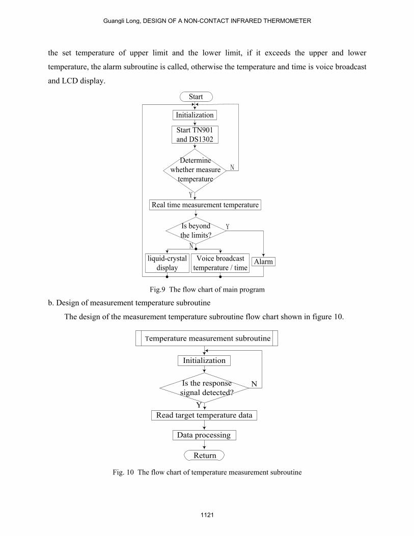
the set temperature of upper limit and the lower limit, if it exceeds the upper and lower
temperature, the alarm subroutine is called, otherwise the temperature and time is voice broadcast
and LCD display.
Initialization
Start TN901
and DS1302
Real time measurement temperature
liquid-crystal
display
Voice broadcast
temperature / timeAlarm
Is beyond
the limits?
N
Y
Y
N
Start
Determine
whether measure
temperature
Fig.9 The flow chart of main program
b. Design of measurement temperature subroutine
The design of the measurement temperature subroutine flow chart shown in figure 10.
Temperature measurement subroutine
Initialization
Is the response
signal detected?
Read target temperature data
Y
N
Data processing
Return
Fig. 10 The flow chart of temperature measurement subroutine
Guangli Long, DESIGN OF A NON-CONTACT INFRARED THERMOMETER
1121

First, the TN901 temperature measurement module is initialized, and then the signal is
transmitted. The program judges whether the response signal of the temperature measurement
module is correct, if it is correct, the data is read, if it is not correct, it will be returned to continue
monitoring the response signal until correct. Finally, the data is processed and returned to the
main program.
c. Design of clock subroutine
Design clock subroutine flow chart as shown in Figure 11, the use of single-chip timer to
achieve the clock.
N
N
Y
Y
Clock subroutine
Variable initialization
Reset end
produces high level
Write 1302 address
Delay 1ms
Write data to
this address
Address increase
Is the data
written?
Delay 1ms
Address data read out
Address increase
Is the data
to be read?
Return
Fig. 11 Clock subroutine flow chart
d. Voice broadcast subroutine
Frame format of SYN6288 supported is: Frame head(FD)+data area length+data area. When
the temperature measurement key is pressed, the temperature value and time to be stored in an
INTERNATIONAL JOURNAL ON SMART SENSING AND INTELLIGENT SYSTEMS VOL. 9, NO. 2, JUNE 2016
1122

array to be broadcast, SYN6288 to the text of the array is synthesized for voice playback. Voice
playback subroutine flow chart shown in figure 12.
Voice broadcast subroutine
Serial port initialization
Broadcast
"Your temperature is"
Broadcast
temperature values
Broadcast "degree"
Broadcast time
Return
Fig. 12 The flow chart of voice broadcast subroutine
According to the flow chart, it is compiled on the KEIL IDE Vision4 platform with the C
programming language [18]
.
V. SOFTWARE COMPILATION AND DOWNLOAD
KEIL IDE Vision4 compilation process is:
(1) Start μVision4, KEIL software integrated development environment is entered, the
"Project→ New Project..." Menu is selected, a directory is selected or created for the New Project
in the pop-up "Creat New Project" dialog box, and the name of the Project file is input, a Project
file (.μv2) is automatically generated. Click the "save" button, select the target chip window.
Target CPU is selected in the window, Keil C51 support a lot of CPU, AT89C51 chip of
Atmel company is selected, click the "ok" button, a dialog box asked if the standard AT89C51
boot file is chosen and added the project, click "yes" button, it will join the rest of the project file.
Return to the main window, "Target1" is appeared in the project window file page, there is
the "+" in front. Click the "+", you can see the next layer of "Source Group1", then click the "+"
in the "Source" Group1, you can see a STARTUP. A51 file. This file is just to join, it is suitable
Guangli Long, DESIGN OF A NON-CONTACT INFRARED THERMOMETER
1123

for most AT89C51 derived series startup file code. Startup code is executed first starting target
chip code in main () function before, it is used to remove data memory, hardware initialization
and again into the stack pointer.
"File→ New..." is selected, a new file input window is opened on the right side of the project
manager, the source program is input in this window, letter of uppercase and lowercase letter and
the semicolon after each row is noticed, don't lose and leakage input wrong. After the input,
"File→ Save" is selected, the File is named and saved. You must add extension, the name of this
design using C language, so the extension is ".c", here it is named "mms. c", if the program is
written in assembly language, the extension is the ".asm". After the file is saved, the window can
be closed.
Then need to manually add source program to the project, click on the "Source Group1",
make its reverse display, and then click the right mouse button, a shortcut menu appears, the Add
file Group "and" Source Group1 "is selected, a dialog box appears, it is asked to find the source
file. Double-click the mms. c file, the file is added to the project. Note that after the file is to join
the project, the dialog does not disappear, waiting for continue to add other documents. At this
point, click the "Close" to return to the main window, after the return, click the plus sign in front
of "Source Group1", mms. c file is in it, double-click the file name, the source program has been
opened.
(2)The project Settings
After building project, further engineering is set to meet the requirements. Double-click the
Project window "Target1" first, and then click the right mouse button, the "Project→ Option for
target" and "Target1"are selected from the shortcut menu, Project Settings dialog box appears.
This dialog has 10 pages, including the driver pages, target pages, output pages, a list of pages,
C51 pages, A51 pages, BL51Locate pages, BL51Misc, debugging and utility pages, most of
items is set by default.
(3)Compile and link
After project settings, it can be compiled and links. Menu "Project → Build target" are
selected, the current engineering is connected, if the current file has been modified, it will be to
compile the file first, and then be connected to generate the target code; If the "Rebuild All target
files" is selected, it will recompile all the files in the current project, and then be connected, the
goal of eventually produce code is to ensure that the latest; The "Translate..." item is compiled
INTERNATIONAL JOURNAL ON SMART SENSING AND INTELLIGENT SYSTEMS VOL. 9, NO. 2, JUNE 2016
1124

only the current file, don't connect. The above operations can also be directly via the toolbar
button, from left to right are: compiling, compile link, all the reconstruction, stop compiling,
download to Flash Memory and to set up the project.
Compile information will appear in the output window in the process of the Build page,
compile results display window as shown in figure 13.
Fig. 13 Compile results display window
If the source has grammatical errors in the program, there will be a bug report, double-click
on the bank, the location of the error can be positioning, compile again after the source program
to modify, until the error is 0. At the same time, the amount of code of the program, internal
RAM usage, external RAM usage information and so on can be seen in the window. In addition,
compile and link also have some other relevant documents, including the relocatable object files
(.obj), relocatable file list. (.lst), an absolute address the target file (no suffix), an absolute address
list file (. m51), connecting the input file (.inp), these can be used for simulation and debugging
of Keil C51 to start debugging after this step.
Pressed Ctrl + F5 key combination or use the menu "Debug→ Start/Stop the Debug Session"
can be entered into a state of debugging. Most of the command on the Debug menu can be found
corresponding shortcut button in the run and Debug toolbar. Generally from left to right in turn is
reset, running, pause, single step, process step, the execution of the current subroutine, run to the
current line, the next state, to open the tracking, observation, the disassembly window,
observation window, code analysis, 1 # serial window, memory window, performance analysis,
tool button command window.
Debug interface diagram as shown in figure 14, after debugging success under the interface
block diagram shows "0 Error (s)".
Download software used on STC official download software, the target file is directly open
after the port is selected, and then click download, and the MCU with electricity, software
download can be completed.
Program download interface as shown in figure 15. If the download is successful, the
"Program OK” will be displayed in the lower left corner block diagram.
Guangli Long, DESIGN OF A NON-CONTACT INFRARED THERMOMETER
1125

Fig. 14 Debug interface diagram
Fig. 15 Program download interface
Ⅵ. THE EXPERIMENTAL RESULTS
All unit circuit are simulated on the Proteus platform, the PCB board is designed and
produced after simulation, the MCU of download the program and other components are welded
on the PCB board [19-20]
, physical diagram is shown in figure 16. power on, the function is test.
INTERNATIONAL JOURNAL ON SMART SENSING AND INTELLIGENT SYSTEMS VOL. 9, NO. 2, JUNE 2016
1126

Fig. 16 Physical diagram
The temperature of the water is simulated by the human body temperature, it is measured at
the same time with mercury thermometer and non-contact infrared thermometer, time is counted
with the clock, the temperature is set at 30oC to 50
oC. The measurement results are: the error of
the temperature is less than 0.2oC, the measurement time is about 4 seconds with the non-contact
infrared thermometer, voice broadcast and LCD display temperature and time, the data is more
accurate. The water temperature of less than 30 oC was detected by non-contact infrared
thermometer, buzzer alarm, voice broadcast: "your temperature is abnormal——Ultra low";
Water temperature at 30 oC ~ 50
oC, voice broadcast and LCD display temperature and time; Over
50oC, buzzer alarm, voice broadcast: "your body temperature abnormal——Super high".
Ⅶ.CONCLUSION
In this paper, the infrared temperature measurement module for the measurement of body
temperature, the measurement of the traditional contact thermometer is avoided, it is particularly
suitable for measuring body temperature for infants and young children. The measured
temperature is displayed through the LCD module, and it has the function of voice broadcast, it
can be used by the man of poor eyesight. Non - contact measurement, measuring speed is quick,
the body temperature is measured in the larger flow of people (such as stations, terminals, etc.).
ACKNOWLEDGEMENT
This paper is supported by the scientific research fund project of Shaanxi Province
Education Office, project number: 2013JK1061; At the same time, this paper is supported by the
Guangli Long, DESIGN OF A NON-CONTACT INFRARED THERMOMETER
1127

science and Technology special plan of Hanzhoung city science and technology development,
project number: 2013hzzx-45.
REFERENCES
[1] C.L. Hao, Y.W Shen, “Study on Production and Mercury Consumption of Clinical Mercury-
Thermometers in China”, Research of Environmental Sciences , vol. 19,no. 1, 2006,pp.18-21.
[2] M. Yan, C.W. Peng, Y.H. Yan, etal ,“The principle of infrared temperature measurement and
error analysis”, Journal of Hunan University,vol.31,no.5, 2004,pp.110-112.
[3] Y. Cui, H.F. Li, “The principle of infrared temperature measuring instrument and Application
Guide”, Automation & Instrumentation , total 14,no.6,2009,pp.103-107.
[4] J. Li,M.D. Liu, Y.K. Zeng, etal, “Study on non contact infrared temperature measurement ”,
Piezo-electrics & Acoustooptics,vol.23,no.3,2001, pp.202-205.
[5] W. Chen, “The Intelligent Monitoring System for Piglets Based on Automatic Control
Algorithm”, Hangzhou Dianzi University,2012.
[6] W.P. Liu, “Measurement and Control Node of oil Automation System Design and
Implementation ”, He Fei University of Technology,2007.
[7] J.Z. Li, “Principle and Practice of Micro controller unit”, Publishing House of Xidian
University,Second Edition, 2008.
[8] W. Wang, S.R. Li, “Temperature acquisition and wireless transmission based on 8051 MCU ”,
Modern electronic technology,vol.34,no.1, 2011, pp. 146-149.
[9] B. Marco, B. John, O.F. Brendan, H. Nicholas and D. Paul , “Low-power wireless liquid
monitoring system using ultrasonic sensors”, International Journal on Smart Sensing and
Intelligent Systems, vol. 8, no. 1, March 2015,pp. 26-44.
[10] Z.H. Xin, G.L. Chen, H. Li, Q.X. Song, L.Y. Hu, etal, “The smart home system based on the
IAP15f2k61s2 and GSM”, International Journal on Smart Sensing and Intelligent Systems, vol. 7,
no. 4, December 2014,pp. 1789 – 1806.
[11] D.G. Yang, T.y. Liu , C.Y. Hu, “Design of an intelligent car for searching track and avoiding
obstacles”, International Journal on Smart Sensing and Intelligent Systems, vol. 8, no. 2, June
2015,pp. 1354 – 1378.
[12] A.J. Shan,“Application of SYN6288 Chinese Speech Synthesis Chip in Smart Sowing
Monitor”, Agricultural Science & Technology and Equipment, total 216,no.6,2012,pp.43-
44,47.
[13] K.Y. Guo, X.J. Chen, B.Ji, “Design of voice broadcast system about car’s speed based on
SYN6288”,Experimental Technology and Management, vol.31,no.1,2014,pp.87-90.
INTERNATIONAL JOURNAL ON SMART SENSING AND INTELLIGENT SYSTEMS VOL. 9, NO. 2, JUNE 2016
1128
[14] X.D. Zhuo, “Design of speech recognition system based on SPCE061A ”, Measurement
and testing technology, vol.39,no.3,2012,pp.5-8.
[15] B. Jiang, “Study and Implementation of the Intelligent control system of Antimony Oxide
Production Process”, Guangxi University,2008.
[16] D.J. Feng,“The Design of Electronic Clock Based on DS1302”,Science &technology
view,no.3,2012,pp.119-121
[17] C. Su,“Production of LCD display calendar based on the MCU controlling ”, Journal of
Yangtze University (natural science edition), vol.10, no. 22, 2013, pp.77-79
[18] L.Z. Rao, “Design of a Multifunction Infrared Phonetic Thermometer ”, Journal of Sanming
University, vol.23, no. 2, 2006, pp.148-152.
[19] C. Chen. “Study on Protel DXP Packaging Components Library”, Modern Electronic
Technique, vol. 32, no. 24, 2009,pp.163-167.
[20] W.X. Cao, “Design of digital thermometer based on AT89C51 MCU ”, Journal of Wuhan
Engineering Institute, vol. 24, no. 3, 2012, pp.32-34.
Guangli Long, DESIGN OF A NON-CONTACT INFRARED THERMOMETER
1129