design of a smoke exhaust from a common - c.ymcdn.comc.ymcdn.com/sites/ · pdf filesmoke...
TRANSCRIPT


Design of a Smoke Exhaust from a CommonReservoir:
Shaping the CompartmentOpening for the Benefits of
Smoke ControlWojciech Węgrzyński
Building Research Institute (ITB)

Smoke exhaust through a common reservoir is a cost-effective smoke removal strategy for large volume, multi-functional buildings

A: Flow through anopening into a common reservoir
B: Fire directly in the atrium/mall –ventilation throughcommon reservoir
C: Removal of the smoke through the compartment wherefire orginated

Dimensioning of the openings is often limitedby the SHEVS design, but can this be a part of the solution, instead of being a part of the problem?

Flow of the Smoke out of a Compartment
• Dimensions of the opening are a keyparameter in the smoke control system design,
• May determine maximum HRR (ventilationcontrolled fire)
• Modeled with great detail in CFD, but difficult to investigate many cases quickly

What Does the Opening Influence?
𝑀𝑀𝑏𝑏 = 𝑓𝑓 ∗ 𝑀𝑀𝑤𝑤
𝑊𝑊 = 𝑤𝑤 + 𝑏𝑏
Width and height of the opening areimportant inputparameters for manyanalytical design methods for SHEVS
03/2
03/109,0 hWQm cw
=

( )( ) ( )bstp hzbWQm 25,031,03/12
0 ++= M. Law (1995)
)25,0(36,0 3/2,
3/1bssetp hzWQm += NFPA 92 (2009)
csssecp QmzWQm 0014,04,116,0 3/2,
3/1 ++= BSI (2003)
What Does the Opening Influence?

It is possible to test complex, individual openings with CFD, but doing that for every single openingis not rational.
There is a need for simple ruleson the opening design, and itsinfluence over SHEVS design.
What Does the Opening Influence?

Tools Chosen by the Author
parametric CFD analysisFroude-number modeling

Numerical Modeling
• ANSYS Fluent (v14.5.0), RANS k-ε, transient analysis• 96 numerical analysis of room with dimensions : 20 x 20 x
5 m• Fire size of 2,50 MW and 5,00 MW• Opening sizes investigated
W = (2,0 – 16,0 m; 2 m increment)H = (2,5 – 5,0 m; 0,5 m increment)
• B-Risk zone model as a cross check

Estimation of the Mass Flow Through an Opening in CFD
Step 1 – a plane in the opening, through which the gas can flow isdescribed as a contour plane

Step 2 – a clip of the plane iscreated, with elements with T > T0 + 10°C
Estimation of the Mass Flow Through an Opening in CFD

Step 3 – anotherclip is created with only elements thathave Vx > 0 m/s (flow towardsoutside)
Estimation of the Mass Flow Through an Opening in CFD

𝑚𝑚𝑂𝑂 = �𝑖𝑖=0
𝑖𝑖=𝑛𝑛
��𝑚𝑖𝑖
Step 4 – sum of mass flow in the
elements iscalculated
Estimation of the Mass Flow Through an Opening in CFD

Scale Modeling
• 1/10th physical scale, 2 x 2 x 0,5 m (20 x 20 x 5 m)• Pool fire source of fire, scaled to represent 2,50 MW fire
(~7,9 kW)• Additional source of aerosol for the visualisation of smoke
flow• Possible opening size of:
W = (2,0 – 24,0 m) H = (2,5 – 5,0 m)


Froude-number modeling CFD analysis


Results of the Analysis (B-Risk)
B-RISK2,50 MW
Opening width2 4 6 8 10 12 14 16
Opening
height
2,5 4,77 6,97 9,17 11,15 12,96 14,65 16,25 17,763 5,69 8,48 11,11 13,44 15,58 17,61 19,50 20,86
3,5 6,57 10,01 13,05 15,72 19,34 21,82 23,74 25,964 7,58 11,55 15,78 19,05 22,04 24,89 28,78 30,07
4,5 8,67 13,68 17,80 21,43 24,76 28,76 29,69 33,075 9,93 15,18 19,60 23,53 27,14 30,23 32,23 39,29
Results for differentopening heights(3,50 – 5,00 m)

Results of the Analysis (Hand calc)
Hand calc2,50 MW
Opening width2 4 6 8 10 12 14 16
Opening
height
2,5 4,30 6,83 8,95 10,85 12,59 14,21 15,75 17,223 5,16 8,20 10,74 13,01 15,10 17,05 18,90 20,66
3,5 6,03 9,57 12,53 15,18 17,62 19,90 22,05 24,104 6,89 10,93 14,32 17,35 20,14 22,74 25,20 27,55
4,5 7,75 12,30 16,12 19,52 22,65 25,58 28,35 30,995 8,61 13,66 17,91 21,69 25,17 28,42 31,50 34,43
03/2
03/109,0 hWQm cw
=
Results for differentopening heights(3,50 – 5,00 m)

Results of the Analysis (CFD)
Hand calc2,50 MW
Opening width2 4 6 8 10 12 14 16
Opening
height
2,5 2,99 5,52 7,62 9,54 11,49 12,3 13,37 13,513 4,79 6,97 9,36 11,53 13,01 13,85 14,63 14,67
3,5 4,79 8,43 11,08 15,31 15,1 15,81 16,15 16,464 5,81 9,37 12,8 15,24 17,03 17,74 18,31 18,7
4,5 6,88 11,46 16,92 16,92 18,47 19,67 17,96 23,625 7,79 12,55 15,98 18,44 20,3 22,66 23,85 25,1
Results for differentopening heights(3,50 – 5,00 m)

Mass Flow as Function of Height of Opening
Zone Model
CFD

Comparison of the Methods for Different
Opening Heights
H = 3,50 m
H = 5,00 m (no downstand)

Results of the Analysis - Comparison
Hand calc vs CFD
Opening width2 4 6 8 10 12 14 16
Opening
height
2,5 19% 15% 12% 9% 13% 15% 22% 19%3 15% 13% 11% 14% 19% 23% 29% 15%
3,5 12% 12% -1% 14% 21% 27% 32% 12%4 14% 11% 12% 15% 22% 27% 32% 14%
4,5 7% -5% 13% 18% 23% 37% 24% 7%5 8% 11% 15% 19% 20% 24% 27% 8%
Zone model vs CFD
Opening width2 4 6 8 10 12 14 16
Opening
height
2,5 37% 21% 17% 14% 11% 16% 18% 24%3 16% 18% 16% 14% 16% 21% 25% 30%
3,5 27% 16% 15% 3% 22% 28% 32% 37%4 23% 19% 19% 20% 23% 29% 36% 38%
4,5 21% 16% 5% 21% 25% 32% 40% 29%5 22% 17% 18% 22% 25% 25% 26% 36%

Interpretation of the Results of Numerical Analysis
• Both height and width of the opening have lesser impact on the amount of smoke transported through an opening, than previouslyattributed
• The best convergence between various methods is obtained atopening size 6-8 m x 3,5 m (approx. 1,5 m of the downstand)
• The wider the opening – larger the difference between methods

Are There Benefits of Large Openings?
Are There Benefits of Large Openings?

Are There Benefits of Large Openings?

Are There Benefits of Large Openings?
Wide Opening Narrow Opening

Smoke Flow Through 2 M Wide Opening
H=3,00 m H=4,50 m

Smoke Flow Through 4 M Wide Opening
H=3,00 m H=4,50 m
H=3,00 m H=4,50 m
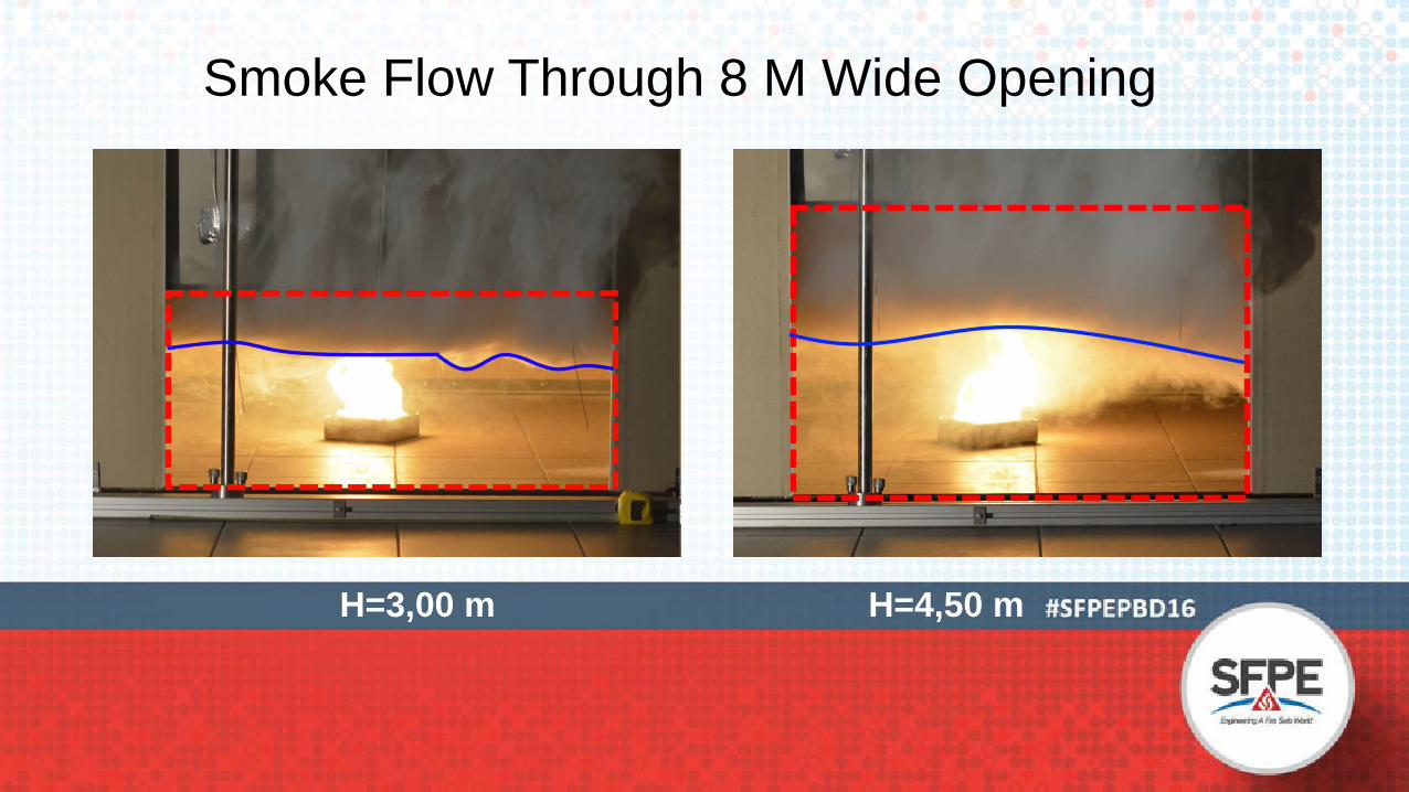
Smoke Flow Through 8 M Wide Opening

W = 4 m, visible layer mixing atthe opening
W = 8 m, stable layer, low mixing
W = 12 m

Practical Example – Very Wide Opening

Practical Example – Very Wide Opening
Mass density of smoke (0-0,20 g/m3)

Practical Example – Additional Openings Under Ceiling

Practical Example – Additional Openings Under Ceiling
Mass density of smoke (0-0,20 g/m3)

Conclusions
• Making openings wider does not influence the mass flow of the smoke out of compartment, as much as we thought
• If opening is not wide enough, tenable conditions inside willbe lost almost immidietly
• If opening is wide enough, the conditions inside the compartment may be tenable without any additional smokeextraction from the compartment

With Correct Dimensioning of Compartment Opening:
• SHEVS design is optimised (often lower capacity required)• Compartment users are protected against smoke• Natural features of the building are used as advantage in
smoke control

Thank You for Your Attention!
Wojciech WęgrzyńskiInstytut Techniki Budowlanej
[email protected]@itb.pl
+48 696 061 589