design of solid spallation targets at psi - cap.bnl.gov · design of solid spallation targets at...
TRANSCRIPT

Kürzel, Datum
Design of Solid Spallation Targetsat PSI
G. Heidenreich
Paul Scherrer Institut, 5232 Villigen PSI
Switzerland

2nd High-Power Targetry Workshop, Oak Ridge, TN, October 10-14, 2005 / G. Heidenreich2
Neutron Spallation Sources at PSI (SINQ)
Beam loss
Target E Station
30 % with 40 mm Target E
SINQ (DC-Operation) 570 MeV, 1.4 mA
Target
D2O-Moderator
p

2nd High-Power Targetry Workshop, Oak Ridge, TN, October 10-14, 2005 / G. Heidenreich3
Neutron Spallation Sources at PSI (UCN)
Ultra Cold Neutron Source UCN(in construction) 590 MeV, 2 mA
UCN-Storage Tank
D2-Moderator (8K)
D2O-Moderator (R.T.)
Target
p

2nd High-Power Targetry Workshop, Oak Ridge, TN, October 10-14, 2005 / G. Heidenreich4
Layout of the SINQ & UCN Solid Targets
UCN-Target:Pulsed operation: 8 seconds beam on (2 mA 590 MeV) 1.2 MW beam power on target; 1% duty cycleBeam parameter: Gaussian beam spot (cut by collimator at R = 2.5 σ); Peak current density 20 μA/cm2
SINQ-Target:Continuous operation: (1.4 mA 570 MeV) 0.8 MW beam power on targetBeam parameter: Gaussian beam spot (cut by collimator II); Peak current density ~35 μA/cm2
p
∅ 212 mm
1 m
p∅ 269 mm
Target hull Target array Shielding Target shaft D O coolant supply2

2nd High-Power Targetry Workshop, Oak Ridge, TN, October 10-14, 2005 / G. Heidenreich5
SINQ - Target
Pb filled stainless steel tubes
Pb filled Zy-2 tubes
Targetcooling
Windowcooling

2nd High-Power Targetry Workshop, Oak Ridge, TN, October 10-14, 2005 / G. Heidenreich6
Power Deposition (590 MeV p-beam)
~70 % of the beam power deposited in the target assembly
flow guides Zy-2 rods or Pb filled Zy-2 tubes Al-clad Pb shielding (320 MeV/p) (1.2 MeV/p)
beam window target hull D2O(4.8 MeV/p) (4.5 MeV/p) (90 MeV/p)
Target cooling18 kg/s D2O
Window cooling2.5 kg/s D2O
UCN - Target

2nd High-Power Targetry Workshop, Oak Ridge, TN, October 10-14, 2005 / G. Heidenreich7
Layout of the Target Array
Target array options: SINQ: UCN:I. solid Zircaloy rods 1996/98II. Pb filled Stainless Steel tubes 1999/2005III. Pb filled Zircaloy tubes 2004/2005 > 2007
11.04 mm
Pb
Transversal pitch12.75 mm
2 mm
Ø 10.75 mm
Stainless Steelor
Zircaloy tubes90 % filled with Pb
Vfluid = 0.5 m/s
dm/dF = 500 kg/s/m2
Tb = 40°C
·

2nd High-Power Targetry Workshop, Oak Ridge, TN, October 10-14, 2005 / G. Heidenreich8
Neutronic Performance
Relative thermal flux
gain
Zy-2 rods(64.5% Zr, 35.5% D2O)
Pb-SS304-Cladding (48% Pb, 11.5% SS304, 34.9% D2O, 5.6% Void)
Pb-Zy2-Cladding
(42.9% Pb, 16.7%Zr, 35.5% D2O, 4.9% Void)
UCN 1) 1.00 *) 1.38 1.61
SINQ 2) 1.00 *) 1.42 1.63 **)
1) M. Wohlmuther, G. Heidenreich Design and neutronic performance of the spallation target of the ultra-cold neutron source UCN at PSI, ICANS-XVII, April 25-29, 2005 Santa Fe, New Mexico
2) E.J. Pitcher, J.R. Lebenhaft, E.H. Lehmann, An Investigation of Neutron Spallation Targets in SINQ usingMCNPX, ICANS-XVI, Proceedings of ICANS-XVI, Düsseldorf-Neuss, Germany May 12-15, Vol. III, p.1191, ISSN 1433-559X (2003).
*) ~ 4.5·10 13 n/cm2/s/mA **) ~ 20 % flux gain for MEGAPIE

2nd High-Power Targetry Workshop, Oak Ridge, TN, October 10-14, 2005 / G. Heidenreich9
Thermo-hydraulic operating regime of the target array
Vfluid = 0.5 m/sdm/dF = 500 kg/s/m2
p = 0.5 MpaTsat = 150 °C
Tbulk = 40 °C
σ : Standard deviationof the Gaussiandistributed beam
σ (cm)
0
1
2
3
4
5
6
7
8
9
0 1 2 3 4 5
Bea
m C
urre
nt (m
A)
UCNSINQ
Critical HeatFlux 3b)
SaturatedBoiling 3a)
High subcooling regime 2)
Forced convection regime 1)
Low subcooling regime 2)
1) V. Gnielinski, VDI-Wärmeatlas,19982) M.M. Shah, Int. J. Heat and Fluid Flow Vol.5, No. 1,1984.3a) M.Z. Hazan et al., J.Heat Trans. 103, 478 (1981).3b) H.J. Ivey , D.J. Morris, UKAEA, AEEW-R137,1962.
·
2nd High-Power Targetry Workshop, Oak Ridge, TN, October 10-14, 2005 / G. Heidenreich10
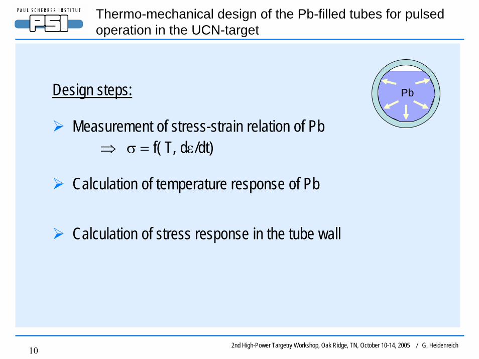
Thermo-mechanical design of the Pb-filled tubes for pulsedoperation in the UCN-target
Design steps:
Measurement of stress-strain relation of Pb ⇒ σ = f( T, dε/dt)
Calculation of temperature response of Pb
Calculation of stress response in the tube wall
Pb

2nd High-Power Targetry Workshop, Oak Ridge, TN, October 10-14, 2005 / G. Heidenreich11
Measured stress-strain relations of Pbstrain rate dε /dt = 7 10-6 s-1
0
1
2
3
4
5
6
7
8
9
0 0.002 0.004 0.006 0.008 0.01
Strain ε
Stre
ss (N
/mm
2 )
20 deg C100 deg C150 deg C
strain rate dε /dt = 0.01 s-1
0
1
2
3
4
5
6
7
8
9
0 0.002 0.004 0.006 0.008 0.01
Strain ε
Stre
ss (N
/mm
2 )
20 deg C100 deg C150 deg C300 deg C (extrapolated)

2nd High-Power Targetry Workshop, Oak Ridge, TN, October 10-14, 2005 / G. Heidenreich12
Temperature & stress response due to the heat load by theproton pulse (peak current density 20 μA/cm2)
Fatigue limit(106 cycles) of Zy-2 :
⇒ 235 N/mm2 (20 °C)
K.U. Snowden et al., J. Nucl. Mat. 67,p.215, 1977.
0
50
100
150
200
250
300
350
0 2.5 5 7.5 10Time (s)
Tem
pera
ture
(°C
)
2. No heat contact Pb-Zy2 (sliding contact)
1. Perfect intermetallic contact Pb-Zy2
Temperature response of Pb
0
50
100
150
200
0 0.5 1 1.5 2 2.5
Time (s)St
ress
(MPa
)
1. Perfect intermetallic contact Pb-Zy2
2. Sliding contact Pb-Zy2 (no heat contact)
Stress response of Zy-2 cladding
dT/dt = 300°C/s
⇒ strain rate: dε/dt = α⋅dT/dt = 0.01 s-1

2nd High-Power Targetry Workshop, Oak Ridge, TN, October 10-14, 2005 / G. Heidenreich13
Temperature & stress distribution
190 N/mm2
10cm
10.7
5 m
m
40 °C
240 °C
2nd High-Power Targetry Workshop, Oak Ridge, TN, October 10-14, 2005 / G. Heidenreich14
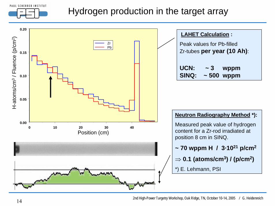
Hydrogen production in the target array
LAHET Calculation :
Peak values for Pb-filledZr-tubes per year (10 Ah):
UCN: ~ 3 wppmSINQ: ~ 500 wppm
0 10 20 30 400.00
0.05
0.10
0.15
0.20
ZrPb
Position (cm)
H-a
tom
s/cm
3/ F
luen
ce(p
/cm
2 )
Neutron Radiography Method *):
Measured peak value of hydrogencontent for a Zr-rod irradiated at position 8 cm in SINQ.
~ 70 wppm H / 3·1021 p/cm2
⇒ 0.1 (atoms/cm3) / (p/cm2)*) E. Lehmann, PSI
2nd High-Power Targetry Workshop, Oak Ridge, TN, October 10-14, 2005 / G. Heidenreich15
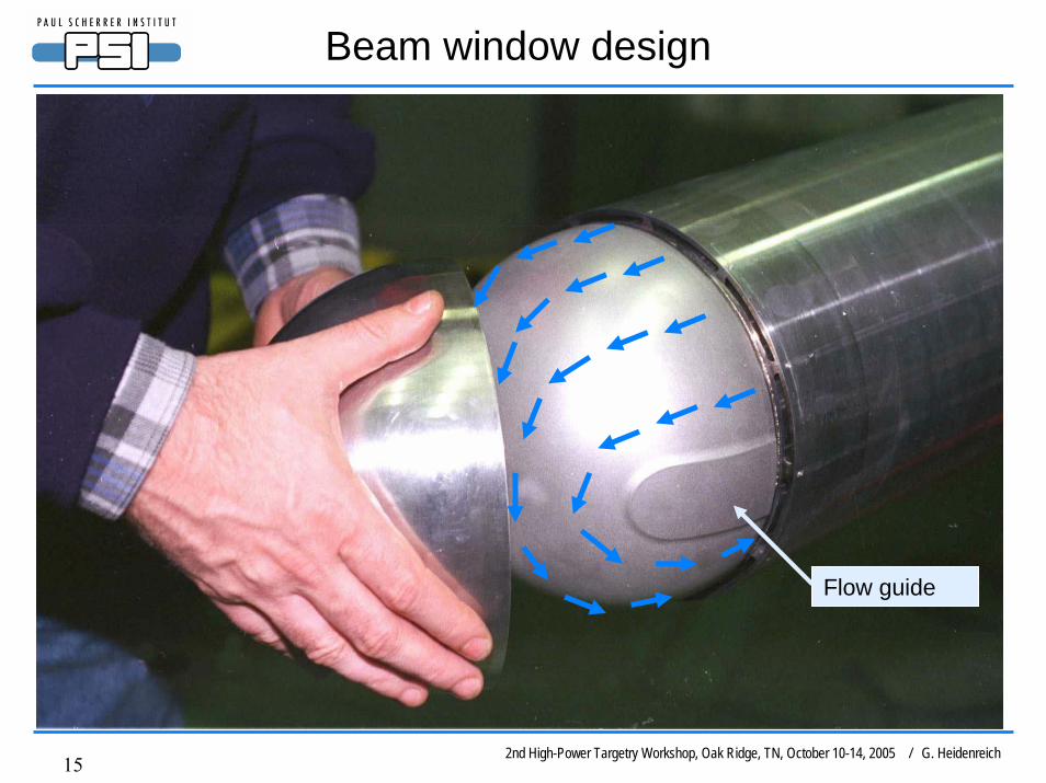
Beam window design
Flow guide

2nd High-Power Targetry Workshop, Oak Ridge, TN, October 10-14, 2005 / G. Heidenreich16
Fluid velocity at window center
UCN : 2.5 m/s
SINQ : 6 m/sMass flow 2.5 kg/s D2O
CFD - Analysis

2nd High-Power Targetry Workshop, Oak Ridge, TN, October 10-14, 2005 / G. Heidenreich17
Thermo-hydraulic operating regimes of the UCN and SINQ window
0
50
100
150
200
250
0 2 4 6 8 10 12 14
Heat Flux (MW/m2)
Wal
l Tem
pera
ture
(°C
) UCN
SINQ
Fluid velocityUCN: 2.5 m/sSINQ: 6 m/s
Normal operation
Forced convection regime
Subcooled boiling regime
M.M. Shah, Heat Transfer Eng., Vol 4, No.1, 1983
Critical heat flux
S. Mirshak et al., SavannahRiver, DP-355,1959
Quadrupol failure320 μA/cm2
Beam misses target E (40 mm)~ 900 μA/cm2
Tsat = 150°C

2nd High-Power Targetry Workshop, Oak Ridge, TN, October 10-14, 2005 / G. Heidenreich18
Thank you for your attention !