design of subsystems of go-kart vehicle -...
TRANSCRIPT

International Journal of Science, Engineering and Technology Research (IJSETR)
Volume 7, Issue 1, January 2018, ISSN: 2278 -7798
18 All Rights Reserved © 2018 IJSETR
Design of subsystems of Go-kart vehicle
Mihir M. Pewekar
Dept. Of Mech. Engineering
Rajiv Gandhi Institute of
technology
Mumbai,India
Pranit P. Sandye
Dept. Of Mech. Engineering
Rajiv Gandhi Institute of
technology
Mumbai, India
Sambhaji D. Gaikwad
Assistant Professor
Dept. Of Mech. Engineering
Rajiv Gandhi Institute of
technology
Mumbai, India
Abstract—Go Kart Design Challenge is a contest
formulated to enhance the approach of students
practicing Engineering and Diploma courses.
This event is fundamentally all about designing
and fabricating a Go Kart at very low
expenditure. The teams are expected to
manufacture Go Karts yielding optimum
performance. The objective of this report is to
document and represent Go-kart designed by
TEAMNFS RGIT to compete in Go-kart Design
Challenge 2016. The team’s primary aim is to
design safe and performance prototype vehicle,
according torules and regulations of the
competition, that can be manufactured on a
large scale. The secondary objective is to
enhance driver’s comfort and safety, and to
increase the performance and maneuverability
of the vehicle.
This report contains the intricate details about
the dimensions and performance parameters of
the prototype go kart.
I. INTRODUCTION
Team NFS RGIT is a team of undergraduate
students from Rajiv Gandhi Institute of technology.
The team consists of 17 members from third and
fourth year Mechanical Engineering department.
The team aims at manufacturing a go kart for
competing in the Go Kart Design Challenge 2016.
We have divided our design task in the following
sub- systems.
Frame design
Braking system
Steering system
Engine and drive train
Electrical
Material and Manufacturing
Fig. 1. Assembled Prototype with safety equipment
A. Project objective
The aim of the project is
To design a prototype vehicle for go-kart
design challenge as per the rules and
regulations.
To enhance the performance of the
vehicle to its optimum level.
International Journal of Science, Engineering and Technology Research (IJSETR)
Volume 7, Issue 1, January 2018, ISSN: 2278 -7798
19 All Rights Reserved © 2018 IJSETR
To practice principles of team
management and to complete the project
in stipulated time.
To enhance knowledge and aid innovation
driven approach towards prototyping.
B. Background to Go-Karting
With time, motorsports are gaining much
popularity in India, the Buddha international circuit
being the proof of the same. The Buddha
international circuit has aided India in getting global
recognitionforFormula 1 racing. The uprising of
Team Sahara force India hasgiven birth to racing
idols Karun Chandhok and Narain Karthikeyan. All
their racing careers started with go-karting.
II. TECHNICAL SPECIFICATION
Dimensions
Overall Length- 1.779 m
Overall width- 1.4 m
Front track width- 1.240 m
Wheel Base- 1.345 m
Ground Clearance- 2.36 inches
Engine Specification
Rated power- 8.58 Bhp
Rated Torque- 9.2 Nm at 4500 rpm
Type - 4 stroke, single cylinder, Over Head
Valves.
Transmission System
Transmission type- Constant variable
Transmission with chain
drive
Driver Sprocket- 17 T
Driven Sprocket- 36 T
Tires Specification-
Front Diameter- 10 inch
Rear Diameter- 11 inches
Rim Size- 5 inches
Steering Specifications:
Type- 4 bar Ackerman linkage
Steering Ratio- 1:1
Turning Radius-3m
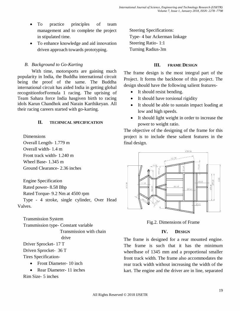
III. FRAME DESIGN
The frame design is the most integral part of the
Project. It forms the backbone of this project. The
design should have the following salient features-
It should resist bending.
It should have torsional rigidity
It should be able to sustain impact loading at
low and high speeds.
It should light weight in order to increase the
power to weight ratio.
The objective of the designing of the frame for this
project is to include these salient features in the
final design.
Fig.2. Dimensions of Frame
IV. DESIGN
The frame is designed for a rear mounted engine.
The frame is such that it has the minimum
wheelbase of 1345 mm and a proportional smaller
front track width. The frame also accommodates the
rear track width without increasing the width of the
kart. The engine and the driver are in line, separated

International Journal of Science, Engineering and Technology Research (IJSETR)
Volume 7, Issue 1, January 2018, ISSN: 2278 -7798
20 All Rights Reserved © 2018 IJSETR
by a firewall. The design includes all the mounting
features for the following
Engine mounting
Steering assembly
Floor pan
Bodyworks
firewall
Seat
Rear axle Mounting
The design is made keeping in mind the dynamic
forces on the frame due to the high-performance
requirement.
C. Material
The Material AISI 4130 (chrome-molybdenum
alloy steel) is used in frame design due its low
carbon content which increases its weldability.
Welding of AISI 4130 steel can be performed by all
commercial methods. AISI 4130 steel can be easily
machined using conventional methods Also it is
easily available in market according to required
specifications. AISI 4130 is chosen for the chassis
because it has structural properties that provide a
low weight to strength ratio. Thus, the Dimensions
of 1-inch outer diameter and wall thickness of 2 mm
for tubing was selected. Thinner wall requires being
welded using TIG (Tungsten inert gas) welding
process which also makes it stronger and efficient to
weld.
D. Material Specification
The material properties are taken from the
material certificate available with vendor during the
time of purchase.
Thematerial properties are as follows.
Ultimate tensile strength: 585 MPa
Yield strength: 460 MPa
Outer diameter: 25.4 mm
Wall thickness: 2 mm
Shear modulus: 80 GPa
Modulus of elasticity: 205 GPa
Poisson's Ratio:0.29
Density:7850 kg/m3
E. Chemical Composition
Table I. Chemical composition
V. SAFETY ANALYSIS
Keeping frame as light weight as possible is key
parameter in determining vehicle performance and
making sure that it performs optimum during
endurance test. Design methodology consisted of
reducing total number structural member without
compromising the rigidity of frame.
FEA aided the material decision making process.
FEA specifically helped to determine whether a
member was under high or low stresses, making the
chassis design process efficient and effective.
The FEA (finite element analysis) is done on
Ansys software. Using Mechanical APDL as the
solver.
These tests simulate conditions of high stress and
evaluate the performance of the frame in handling
those stresses. Further, these test help in determining
the factor of safety of the vehicle.
To conduct the safety test, we have used EURO -
New Car AssessmentProtocols. (NCAP)
Sr No.
Chemical
composition
Percentage (%)
1 Fe 97.772
2 C 0.29
3 Si 0.24
4 Mo 0.18
5 Cr 0.94
6 Ni 0.003
7 S 0.007
8 P 0.012
9 Mn 0.54
10 Al 0.016

International Journal of Science, Engineering and Technology Research (IJSETR)
Volume 7, Issue 1, January 2018, ISSN: 2278 -7798
21 All Rights Reserved © 2018 IJSETR
F. Front Impact Test
The front impact test force as per NCAP is
calculated by the change in momentum in unit
interval of time (1 second). Hypothetically, the car is
given a velocity of 64 Kmph and stopped in one
second interval. This gives an impact force on the
frame. The analysis based on the
mass of the vehicle = 160 kg
V= 64 kmph = 64 x 0.277 m/s = 17.77 m/s
momentum gain = m x V = 160 x 17.77 =2843.2
kgm/s
rate of change of momentum= 2843 .2−0
1=2843.2 N
Force applied in ANSYS= 3000 N (using ceiling
function to roundoff)
Hence the calculated force is applied on the front
member of the modal chassis, keeping the rear
member fixed. The total deformation is shown in the
fig below.
Fig 2. Total deformation in front Impact test
Fig 3. Factor of safety in Front impact test
G. Side Impact Test
The similar principle is applicable to side impact
test. The force is applied on the side bumper. The
speed of the vehicle is 32 kmph
mass of the vehicle = 160 kg
V= 64 kmph = 32 x 0.277 m/s = 8.864 m/s
momentum gain = m x V = 160 x 8.864 =1418
kgm/s
rate of change of momentum= 1418 −0
1=1418 N
Force applied in Ansys=1600 N ( taking 1g force)
Hence the calculated force were placed on one
side of the modal of frame while keeping another
side fixed and the stresses were simulated the image
is shown as-
Fig 4. Total deformation in front Impact test
Fig 5. Factor of safety in side impact test

International Journal of Science, Engineering and Technology Research (IJSETR)
Volume 7, Issue 1, January 2018, ISSN: 2278 -7798
22 All Rights Reserved © 2018 IJSETR
H. Rear Impact Test
The similar concept is applicable. The speed of
the vehicle is taken to be as 50 kmph
mass of the vehicle = 160 kg
V= 64 kmph = 50 x 0.277 m/s = 13.85 m/s
momentum gain = m x V = 160 x 13.85 =2216
kg.m/s
rate of change of momentum= 2216 −0
1 =2216 N
Force applied in ANSYS= 2200 N (taking closest
integral value)
Hence the calculated value of the rear impact
force was placed on the rear part of the frame while
keeping the frontal part fixed. The analysis result is
shown as-
Fig 7. Total deformation in front Impact test
Fig 6. Factor of safety in rear impact test
I. Factor of safety
The Results obtained from ANSYS are indicative
of static loading by keeping a certain member of the
frame fixed. Thus, the actual deformation and safety
values obtained may be considered as the crushing
of the frame in one particular plane. The Dynamic
characteristics of a frame will differ. It would
involve crash testing of a similar shaped design with
strain gauges to know how loads are distributed
during an impact. Since such data isn't available, the
above ANSYS results can be considered as
sufficient to validate the frame design. In every case
of the testing the minimum factor of safety obtained
is 2.
VI. STEERING
We have considered Ackermann’s geometry to
design the steering system of our go-kart. We
preferred trapezoidal steering system for a go-kart
rather than ‘rack and pinion’ considering the high
expenses and complex designing. We have used
minimum components for the steering assembly in
order to restrict the free play angle below 7° as per
the rule book.
A. Steering Angles-
Castor Angle- 5° Positive
Camber- 2°
Ackerman angle- 28.57°
Reasons for Camber and Castor-
1) Camber In case of Positive camber, as the vehicle turns
the outside wheels tend to rise. When the wheel
returns to straight ahead position, the weight of the
vehicle presses down on the steering axis and this
help in straighten the wheel. Positive camber aids in
wheel return after completing the turn.
2) Castor In rear wheel drive vehicles, the steering axis
pulls the front tires, whereas the tire drag on
account of the vehicle weight is on the vertical line
at the center of the footprint. Since in positive castor
steering axis would meet the ground ahead of the
center of tyre print, the latter would always follow
the former. Thus, positive castor provides
International Journal of Science, Engineering and Technology Research (IJSETR)
Volume 7, Issue 1, January 2018, ISSN: 2278 -7798
23 All Rights Reserved © 2018 IJSETR
directional stability i.e. straight-line tracking is
improved.
B. Steering Calculations
Track width (T) =1240 mm
Wheel Base (L)= 1345.75mm
The turning angle of the inner wheel is positively
locked at 40°.
For correct Steering,
𝐶𝑜𝑡∅ − 𝑐𝑜𝑡𝜃 =880
1345 .75=0.654
Distance of center of gravity from rear track
width= 0.815 m
To obtain turning radius R= 3
𝑅 = 𝑅12 + 𝐶2
𝑅1 = 𝑅2 − 𝐶2 = 2.887
Fig 8. Steering Geometry
𝜃 = tan−1(𝐿
𝑅1 + 𝑇2
) = 28.79°
∅ = tan−1(𝐿
𝑅1 − 𝑇2
) = 22°
C. Ackerman Angle
From above values,
𝑡𝑎𝑛𝛼 =𝑠𝑖𝑛∅−𝑠𝑖𝑛𝜃
𝑐𝑜𝑠𝜃 +𝑐𝑜𝑠∅−2=28.57°
D. Length of tie Rod
𝑠𝑖𝑛𝛼 =𝑦
𝑆𝑙
therefore, y= 64.57 mm
𝑐𝑜𝑠𝛼 =𝑧
𝑆𝑙
Therefore, z= 118.55
Length of tie rods(P)= 800−(64.57 𝑥 2)
2 = 357.43
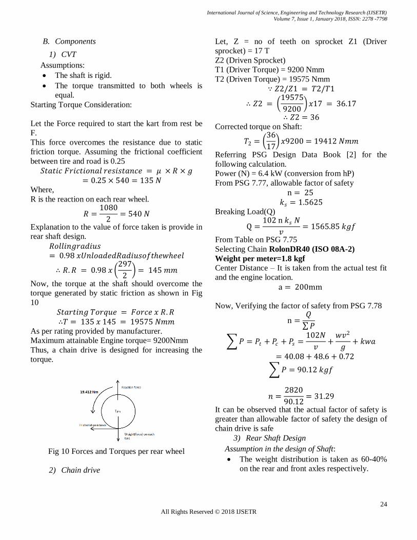
E. Analysis of Steering Pivot
The dynamic force analysis was conducted on
ANSYS software. The factor of safety is
Fig9. Factor of safety on knuckle.
VII. TRANSMISSION
A. Basic Overview
CVT is an automatic transmission that can select any
desired drive ratio within its operating range.
A CVT has three main components
1. Variable input driving pulley
2. An output or driven pulley.
3. Metal belt
The driving pulley is connected to the engine
crankshaft while the driven pulley transfers the
motion to the drive shaft. As the two pulleys change
their diameters relative to each other, infinite
number of gear ratios are obtained.
Advantages of using CVT in our prototype vehicle:
1. Constant step-less acceleration from start to
high speed eliminating shift shock.
2. It keeps the car in optimum power range
under all conditions, thus giving a better fuel
economy.
3. Less emissions due to better engine control
in all conditions.
International Journal of Science, Engineering and Technology Research (IJSETR)
Volume 7, Issue 1, January 2018, ISSN: 2278 -7798
24 All Rights Reserved © 2018 IJSETR
B. Components
1) CVT
Assumptions:
The shaft is rigid.
The torque transmitted to both wheels is
equal.
Starting Torque Consideration:
Let the Force required to start the kart from rest be
F.
This force overcomes the resistance due to static
friction torque. Assuming the frictional coefficient
between tire and road is 0.25
𝑆𝑡𝑎𝑡𝑖𝑐 𝐹𝑟𝑖𝑐𝑡𝑖𝑜𝑛𝑎𝑙 𝑟𝑒𝑠𝑖𝑠𝑡𝑎𝑛𝑐𝑒 = 𝜇 × 𝑅 × 𝑔 = 0.25 × 540 = 135 𝑁
Where,
R is the reaction on each rear wheel.
𝑅 =1080
2= 540 𝑁
Explanation to the value of force taken is provide in
rear shaft design.
𝑅𝑜𝑙𝑙𝑖𝑛𝑔𝑟𝑎𝑑𝑖𝑢𝑠= 0.98 𝑥𝑈𝑛𝑙𝑜𝑎𝑑𝑒𝑑𝑅𝑎𝑑𝑖𝑢𝑠𝑜𝑓𝑡𝑒𝑤𝑒𝑒𝑙
∴ 𝑅. 𝑅 = 0.98 𝑥 297
2 = 145 𝑚𝑚
Now, the torque at the shaft should overcome the
torque generated by static friction as shown in Fig
10
𝑆𝑡𝑎𝑟𝑡𝑖𝑛𝑔 𝑇𝑜𝑟𝑞𝑢𝑒 = 𝐹𝑜𝑟𝑐𝑒 𝑥 𝑅.𝑅 ∴𝑇 = 135 𝑥 145 = 19575 𝑁𝑚𝑚
As per rating provided by manufacturer.
Maximum attainable Engine torque= 9200Nmm
Thus, a chain drive is designed for increasing the
torque.
Fig 10 Forces and Torques per rear wheel
2) Chain drive
Let, Z = no of teeth on sprocket Z1 (Driver
sprocket) = 17 T
Z2 (Driven Sprocket)
T1 (Driver Torque) = 9200 Nmm
T2 (Driven Torque) = 19575 Nmm
∵ 𝑍2/𝑍1 = 𝑇2/𝑇1
∴ 𝑍2 = 19575
9200 𝑥17 = 36.17
∴ 𝑍2 = 36
Corrected torque on Shaft:
𝑇2 = 36
17 𝑥9200 = 19412 𝑁𝑚𝑚
Referring PSG Design Data Book [2] for the
following calculation.
Power (N) = 6.4 kW (conversion from hP)
From PSG 7.77, allowable factor of safety
n = 25 𝑘𝑠 = 1.5625
Breaking Load(Q)
Q =102 n 𝑘𝑠 𝑁
𝑣= 1565.85 𝑘𝑔𝑓
From Table on PSG 7.75
Selecting Chain RolonDR40 (ISO 08A-2)
Weight per meter=1.8 kgf
Center Distance – It is taken from the actual test fit
and the engine location.
a = 200mm
Now, Verifying the factor of safety from PSG 7.78
n =𝑄
𝑃
𝑃 = 𝑃𝑡 + 𝑃𝑐 + 𝑃𝑠 =102𝑁
𝑣+
𝑤𝑣2
𝑔+ 𝑘𝑤𝑎
= 40.08 + 48.6 + 0.72
𝑃 = 90.12 𝑘𝑔𝑓
𝑛 =2820
90.12= 31.29
It can be observed that the actual factor of safety is
greater than allowable factor of safety the design of
chain drive is safe
3) Rear Shaft Design
Assumption in the design of Shaft:
The weight distribution is taken as 60-40%
on the rear and front axles respectively.
International Journal of Science, Engineering and Technology Research (IJSETR)
Volume 7, Issue 1, January 2018, ISSN: 2278 -7798
25 All Rights Reserved © 2018 IJSETR
The load on each bearing is equal in the
vertical plane.
The load in the horizontal plane is only due
to the friction force from the tire and due to
the brake rotor during breaking.
The ASME code for shafts is used to
consider the high fluctuating load.
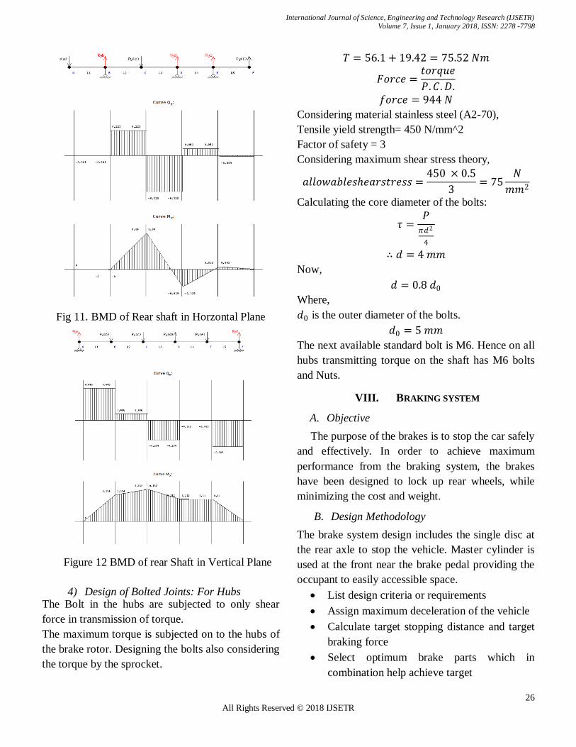
The free body diagrams, the BMD and SFD of the
shaft are shown Fig 11. and Fig 12.
Consider the forces in the vertical plane:Refer to fig
12
Lengths:
L1 = 300 mm
L2 = 362.5 mm
L3 = 181.25 mm
L4 = 181.25 mm
L5 = 300 mm
rearweight = 0.6 x 1800 = 1080N
And,
𝑤𝑒𝑖𝑔𝑡𝑜𝑛𝑒𝑎𝑐𝑏𝑒𝑎𝑟𝑖𝑛𝑔 = 1080/3 = 360𝑁
Let the reaction on each tire be Ra and
Rbrespectively.
𝑃𝑦𝑏 = 360 𝑁𝑚−1
𝑃𝑦𝑐 = 360 𝑁𝑚−1
𝑃𝑦𝑑 = 266.4 𝑁𝑚−1
𝑃𝑦𝑒 = 360 𝑁𝑚−1
Calculating Ra and Rb:
𝑅𝑎 = 446 𝑁 𝑅𝑏 = 368 𝑁
Consider the Forces in the horizontal Plane: Refer
to Fig 11
Lengths:
L1 = 300 mm
L2 = 181.25 mm
L3 = 181.25 mm
L4 = 362.5 mm
L5 = 300 mm
Forces:
𝑃𝑦𝑎 = 360 𝑁𝑚−1
𝑃𝑦𝑐 = 360 𝑁𝑚−1
𝑃𝑦𝑓 = 266.4 𝑁𝑚−1
Calculating Rb, Rcand Re:
𝑅𝑏 = 225 𝑁 𝑅𝑐 = 388 𝑁 𝑅𝑒 = − 70 𝑁
From the Bending moment diagrams in Fig 10 and
Fig 11;
We consider only the Maximum bending moment in
the vertical as well as the horizontal plane.
𝑀𝑣(max ) = 162 × 103𝑁𝑚𝑚
𝑀(max ) = 40 × 103𝑁𝑚𝑚
Equivalent Bending moments;
𝑀𝑏 = 𝑀𝑣(max )2 + 𝑀(max )
2
𝑀𝑏 = 166865.21 𝑁𝑚𝑚 Equivalent force on Each Bearing:
𝐵1 = 3602 + 𝑅𝑏2 = 424.53 𝑁
𝐵2 = 3602 + 𝑅𝑐2 = 529.28 𝑁
𝐵3 = 3602 + 𝑅𝑒2 = 366.74 𝑁
Torque on shaft (derived in previous section):
𝑀𝑡 = 19412 𝑁𝑚𝑚 Equivalent Torsional Moment:
As per the ASME code (from PSG Data book page
7.21),
𝑀𝑡𝑒𝑞 = (𝑘𝑏 × 𝑀𝑏)2 + (𝑘𝑡 × 𝑀𝑡)2
Where,
Kb = 2 and Kt= 1.5 (these are the combined shock
and fatigue factors in bending and torsional moment
respectively)
Shaft Material: Carbon steel – Grade C50
Yield strength = 460 MPa
The factor of safety can be assumed as 3.
𝑃𝑒𝑟𝑚𝑖𝑠𝑠𝑖𝑏𝑙𝑒 𝑠𝑒𝑎𝑟 𝑠𝑡𝑟𝑒𝑠𝑠(𝜏𝑚𝑎𝑥 ) =460 × 0.5
3= 76.66𝑀𝑝𝑎
According to maximum shear stress theory:
𝜏𝑚𝑎𝑥 = 16 ×𝑀𝑡𝑒𝑞
𝜋𝑑3
Now, calculating the Shaft diameter
𝑑 = 28.1 𝑚𝑚
The shaft diameter is rounded off to the next
standard size.
Therefore,
𝑑 = 30 𝑚𝑚
International Journal of Science, Engineering and Technology Research (IJSETR)
Volume 7, Issue 1, January 2018, ISSN: 2278 -7798
26 All Rights Reserved © 2018 IJSETR
Fig 11. BMD of Rear shaft in Horzontal Plane
Figure 12 BMD of rear Shaft in Vertical Plane
4) Design of Bolted Joints: For Hubs The Bolt in the hubs are subjected to only shear
force in transmission of torque.
The maximum torque is subjected on to the hubs of
the brake rotor. Designing the bolts also considering
the torque by the sprocket.
𝑇 = 56.1 + 19.42 = 75.52 𝑁𝑚
𝐹𝑜𝑟𝑐𝑒 =𝑡𝑜𝑟𝑞𝑢𝑒
𝑃.𝐶. 𝐷.
𝑓𝑜𝑟𝑐𝑒 = 944 𝑁
Considering material stainless steel (A2-70),
Tensile yield strength= 450 N/mm^2
Factor of safety = 3
Considering maximum shear stress theory,
𝑎𝑙𝑙𝑜𝑤𝑎𝑏𝑙𝑒𝑠𝑒𝑎𝑟𝑠𝑡𝑟𝑒𝑠𝑠 =450 × 0.5
3= 75
𝑁
𝑚𝑚2
Calculating the core diameter of the bolts:
𝜏 =𝑃
𝜋𝑑2
4
∴ 𝑑 = 4 𝑚𝑚
Now,
𝑑 = 0.8 𝑑0
Where,
𝑑0 is the outer diameter of the bolts.
𝑑0 = 5 𝑚𝑚
The next available standard bolt is M6. Hence on all
hubs transmitting torque on the shaft has M6 bolts
and Nuts.
VIII. BRAKING SYSTEM
A. Objective
The purpose of the brakes is to stop the car safely
and effectively. In order to achieve maximum
performance from the braking system, the brakes
have been designed to lock up rear wheels, while
minimizing the cost and weight.
B. Design Methodology
The brake system design includes the single disc at
the rear axle to stop the vehicle. Master cylinder is
used at the front near the brake pedal providing the
occupant to easily accessible space.
List design criteria or requirements
Assign maximum deceleration of the vehicle
Calculate target stopping distance and target
braking force
Select optimum brake parts which in
combination help achieve target

International Journal of Science, Engineering and Technology Research (IJSETR)
Volume 7, Issue 1, January 2018, ISSN: 2278 -7798
27 All Rights Reserved © 2018 IJSETR
Optimize brake design
C. Elements of the Braking System
5) Brake pedal-
The pedal was designed with the pedal ratio 4.
6) Master cylinder
The TVS Apache RTR master cylinder with bore
Diameter 16 mm proved to be best suited for the
design. The single piston master cylinders were
used.
7) Calliper and Rotor.
Apache RTR single piston calipers were selected
due to their light weight easy availability and
reliability. We select Apache RTR rotor. The
following are its dimensions.
1). Dimensions of the rotor = 200 mm,
2). Thickness of the rotor = 3.5 mm
D. Brake calculations
Assumption in the design of Braking System:
The maximum force the driver can apply in
the pedal is 25 kgf.
The sudden application of the brake arrests
the rotational kinetic energy.
The translational kinetic energy is reduced
by the action of friction during skidding due
the absence of rolling motion.
Rules and regulations: For braking Test given
by GKDC organizers
The vehicle must be accelerated to 40
km/h before application of brake
The vehicle must stop in 150 ft. (45.72
m).
By work energy principle,
Kinetic energy of the vehicle (Translation energy +
Rotation energy) = Work done by friction
But, sudden application of the brake will cause the
instant locking of the rear axle. Thus, the brake will
contribute in arresting the rotation of the shaft and
preventing the rotation of the shaft. The vehicle is
stopped by the skidding of the rear wheels. By this
methodology we can reduce the equation to, 1
2𝐼𝜔2 = 𝑇 × 𝜃
Where,
𝜔 is the angular velocity of the wheels.
𝐼 is the moment of inertia of the rear axle (shaft,
hubs, brake rotor, wheels and the chain sprocket)
T is the braking torque needed to lock the rear axle
in 1.5 second.
𝜃 is the angular displacement in 1.5 seconds.
From the CAD model,
𝐼 = 0.8 𝑘𝑔𝑚2 Assuming the braking is performed from 40
km/h(for safety)
𝜔 = 𝑣
𝑟=
40000 × 2
3600 × 0.297= 74.82 𝑟𝑎𝑑/𝑠
∴ 𝜃 = 1 × 𝜔 = 74.82 𝑟𝑎𝑑
Therefore, the minimum torque required
𝑇 =
1
2𝐼𝜔2
𝜃=
2239.2
74.82 = 29.928 𝑁𝑚
Now, Calculating maximum torque available in the
hydraulic braking system.
The pedal ratio (i.e. the leverage) is taken as 5.
Force on the Master cylinder piston:
𝐹𝑚𝑐 = 250 x 5 = 1250 N
Area of the Master piston
𝐴𝑚𝑐 = π
4 × 0.0162 = 2.01 × 10⁻⁴m2
Pressure developed in the system
P =force
area =
1250
2.01 × 10−4= 6218905.47
N
m2
Geometric Dimensions of the caliper pads:
Outer radius: R0 =95 mm
Inner Radius: Ri =90 mm
Arc made by the caliper: α = 30 degrees
Area of the Pads:
𝐴𝑝 =𝛼
2𝜋𝜋 𝑅0
2 − 𝑅𝐼2 = 2.42 × 10⁻⁴𝑚2
Actuation force by the caliper pads on the rotor:
𝐹 = 𝑃 × 𝐴𝑝 = 1504.97 N
Effective rotor radius is calculated by uniform
pressure theory:
International Journal of Science, Engineering and Technology Research (IJSETR)
Volume 7, Issue 1, January 2018, ISSN: 2278 -7798
28 All Rights Reserved © 2018 IJSETR
𝑅𝑓 = 2
3
(𝑅03 − 𝑅𝑖
3)
(𝑅02 − 𝑅𝑖
2)= 0.0925 𝑚
Braking Torque available:
𝑀𝑡 = 𝜇 × 𝐹 × 𝑅𝑓 = 48.72 𝑁𝑚
The required torque is less than the available torque.
𝑀𝑡 > 𝑇 This design of braking system with its components
are within safe limits and this system can be used
for the braking of this vehicle.
Calculation of the Stopping distance:
By work- energy principle,
As per above stated assumptions,
Translational Kinetic energy at 40 km/h = work
done by friction in skidding 1
2 𝑚 𝑣2 = 𝜇𝑟𝑜𝑎𝑑 × 𝑚 × 𝑔 × 0.6 × 𝑠
Where,
0.6 factor is taken to consider 60-40 weight
distribution in the rear and front axle.
𝜇𝑟𝑜𝑎𝑑 =0.35
S is the stopping distance.
𝑠 = 29.39 𝑚 The actual stopping distance is less than the
regulated stopping distance by the GKDC i.e.
45.2m. Thus, this design is safe and complete.
Now, calculating the stopping Time:
𝑣2 = 𝑢2 + 2𝑎𝑠
Acceleration =2.1 m/s^2
𝑣 = 𝑢 + 𝑎𝑡
Time (t) =5.29 s
IX. SAFETY REQUIREMENTS
Following are the safety features included according
to the rule book –
Kill switches – 2 of them, one beneath
the steering, one to side of seat and one
on external chassis
Fire wall – Asbestos sheet is used as the
fire wall as it is a heat insulating material.
Fire extinguisher – there are 2 of
them…one on the vehicle close to the
seat and second with a team member
Rear brake light and rear-view mirror –
both elements are incorporated as per rule
book specifications
X. ELECTRICAL SYSTEMS
A. Objective:
The electrical are designed to fulfill:
To perform efficient starting and running of the
vehicle.
To fulfil the mandatory safety of the go-kart and
driver.
To provide full instrumentation in self-starting
the engine.
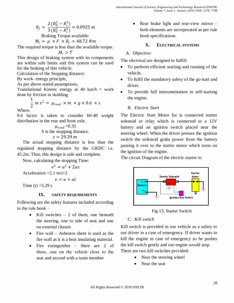
B. Electric Start
The Electric Start Motor for is connected starter
solenoid or relay which is connected to a 12V
battery and an ignition switch placed near the
steering wheel. When the driver presses the ignition
switch the solenoid grabs power from the battery
passing it over to the starter motor which turns on
the ignition of the engine.
The circuit Diagram of the electric starter is:
Fig 13. Starter Switch
C. Kill switch
Kill switch is provided in our vehicle as a safety to
our driver in a case of emergency. If driver wants to
kill the engine in case of emergency so he pushes
the kill switch gently and our engine would stop.
There are two kill switches provided:
Near the steering wheel
Near the seat

International Journal of Science, Engineering and Technology Research (IJSETR)
Volume 7, Issue 1, January 2018, ISSN: 2278 -7798
29 All Rights Reserved © 2018 IJSETR
Fig 14 Kill switch and brake over travel switch
D. Brake Over Travel Switch
Brake over travel switch is provided at the
placement of pedal,to turn off the engine when
brake failure occurs.
E. Brake lights
Brake lights are essential for alarming the driver
behind in order to avoid collision.
Figure 13 Brake Light Circuit
XI. SEAT AND SEATING ARRANGEMENT
It can be observed from Fig18. the seat is placed
at a considerable distance from the engine. The
clearance between the seat and engine is 7 inches
and it allows for the placement of a firewall in
between the seat and engine. The seating
arrangement allows for easy access from either side
of the kart.
XII. ERGONOMICS
Considering Ergonomics, driver was made to sit in
the actual scale model of the kart frame
• The floor was considered as the base floor of the
Kart
• Driver sitting angles measured for a 5’7” person
and a 6’6” person. Both drivers remained in the
position for 20 minutes, thereby simulating driving
conditions
• An optimum seat position was fixed considering
their reviews and all the other member’s reviews
• Various Body Part angles measured, and
clearances were measured
F. Ergonomic measurements
Height of driver- 5'7"
Knee Angle for 5’7” Driver =145 degrees
Thigh Angle for 5’7” Driver = 105 degrees
Elbow Angle for 5’7” Driver = 130degrees
Distance between Chest and steering wheel for 5’7” Driver = 24cm Distance
Seat Backrest Elevation Angle = 115 degree from horizontal
Fig 15. Ergonomic position on 1:1 PVC Model
Figure 16 Isometric view with humanoid

International Journal of Science, Engineering and Technology Research (IJSETR)
Volume 7, Issue 1, January 2018, ISSN: 2278 -7798
30 All Rights Reserved © 2018 IJSETR
XIII. VEHICLE DIMENSIONING AND CAD
GENERATED VIEWS
Figure 17. Side View in the CAD Model
Figure 18. Side View in the CAD Model
Figure 19. Side View in the CAD Model
Figure 20 Side View in the CAD Model
Figure
XIV. ACKNOWLEDGMENT
Our deep gratitude first goes to MukeshKurlawala
of Chamunada Engineering Corporation, who has
have painstakingly and patiently put their time and
effort. We thank them for the equipment’s provided
for the manufacturing of this project.
We express our sincere thanks to our sponsor Sujay
Suvarna of Chase Resource Management Pvt. Ltd,
without whom this project wouldn't reach its
completion.Also, we express our thanks to our
project advisor Mr. Mangesh Pewekar who has
perfectly guided us through the making of our
project and who shared his valuable information and
knowledge with each member of our team.
Our appreciation also extends to the library staff for
the books and study/references material which
proves to be of great help for preparation of the
project.
Above ground, we are indebted to our families,
whose values grows with age.
International Journal of Science, Engineering and Technology Research (IJSETR)
Volume 7, Issue 1, January 2018, ISSN: 2278 -7798
31 All Rights Reserved © 2018 IJSETR
XV. REFERENCES
A. Stephen P. Timoshenko and James M. Gere
on Theory of Elastic stability, 2nd ed., McGraw-Hill International, 1963, pp.1-37
B. Dr. Kirpal Singh on Automobile Engineering,
12th ed., vol. 1. Standard publisher
distributors, 2011.
C. Design data Book published by Kalaikathir
Achchagam, 1978.
D. R. C. Hibbeler on engineering mechanics
(Statics and dynamics), 5th ed. Macmillan
publishing company, 1989.
E. Gere and Timoshenko on Mechanics of
materials, 2nd ed. CBS publisher and distributors, 1986.
F. V B. Bhandari on design of machine
elements, 2nd ed. Tata McGraw-Hill, 2007.