design or improvement of fire hose drying system through
TRANSCRIPT
Design or improvement of fire hose drying
system through technology research of fire
hose maintenance sectors and other industrial
sectors
EUROPEAN PROJECT SEMESTER 2010
FINAL REPORT
Company: Rud. Prey GmbH & Co. KG
Team Members: Christopher Dollarhide
Carlos Alberto Herrer
Nadine Kunze
Simon Sirven
Egidijus Vitkus
Supervisor: Mr. Prof. Dr. rer. nat. Sönke Schmidt
Date: 4 June 2010
Rud. Prey
II
Abstract
In this project, provided by Rud. Prey GmbH & Co. KG, we focussed on methods for drying
fire hoses, and based on this design or improve a fire hose drying system. Nowadays, many
different systems for this purpose exist on the market. Thus, our first step was to find all
systems and compare several common methods in a decision matrix. Next, we researched
current drying technologies in industrial sectors such as, chemical, mechanical, radioactive,
conductive, and convective drying. After evaluating them with respect to fire hoses, we
concentrated on the applicable ones and performed experiments, in order to find the best
combination of technologies. Power and energy calculations were made to support the results.
Based on these results, we were able to suggest a combination of suction, microwave and hot
air forced convection what could be easily integrated in the Horizontal Process Dryer of Prey.

Rud. Prey
III
Declaration of Authorship
I certify that the work presented here, is to the best of my knowledge and belief, original and
the result of my own investigations, except as acknowledged.
Kiel, 4 June 2010 Christopher Dollarhide
Kiel, 4 June 2010 Carlos Alberto Herrer
Kiel, 4 June 2010 Nadine Kunze
Kiel, 4 June 2010 Simon Sirven
Kiel, 4 June 2010 Egidijus Vitkus

Rud. Prey
IV
Acknowledgement
We would like to express our sincerest gratitude to all those who made it possible for us to
complete this project. First and foremost we would like to thank our supervisor, Prof. Dr. rer.
nat. Sönke Schmidt, for his help, support, and guidance during the entire project.
Our deepest gratitude is also due to Mr. Thomas Prey and Ms. Marlies Böll from Rud.Prey
GmbH & Co. KG for their help and support during in-depth discussions related to the project
and for providing us with important information.
Special thanks go to Dipl.-Ing. Claudius Techow for driving us to Zeven and for providing us
with devices needed for our experiments, and for the possibility to perform these in the
machine hall.
We appreciate the help of Ms. Bettina Kunze for entrusting us with her car and supporting us
with devices for our experiments.
We also wish to convey special thanks to Mr. Warias (FTZ Steinburg), Mr. Jahns (BF Kiel)
and Mr. Dettmer (FTZ Zeven) for giving us a detailed view into the working process of fire
hose maintenance systems and equipment.
We are also very grateful for the opportunity given us by the University of Applied Sciences
Kiel, by allowing us to work on this project. We would also like to thank our home
universities for their encouragement during our studies and also their work on international
relations, which made it possible for us to embark on an intercultural project like this.
Finally, a big thank you goes to all of the assisting teachers, Ms. Renate Hahn and Ms.
Christine Boudin from the International Office at University of Applied Sciences Kiel, and
our friends and parents who supported us during this enriching process.
Rud. Prey
V
Confidentiality Undertaking
This report is written to the University of Applied Sciences Kiel and to Rud. Prey GmbH &
Co. KG. Due to firm secrets this report is not public and the selling of copies is prohibited.

Rud. Prey
VI
Workload
In a technical project like this it is not always possible to divide tasks because some parts are
closely connected and should or might have to be done by two or more team members. The
experiments and suggestions were done as a team and discussions were made to ensure the
understanding of all members throughout the project.
Performing the experiments for example was a task that was shared.
Simon Sirven, Christopher Dollarhide, and Carlos Alberto Herrer concentrated on both the
results and conclusions of the experiments as well as, the power calculations for different
drying methods tested during the experiments.
Christopher Dollarhide and Nadine Kunze wrote the Chapter about the Decision Matrix.
Egidijus Vitkus was focused on fire hoses as well as infrared, radio frequency and flash
drying technologies.
Nadine Kunze did the work on the description of Rud. Prey GmbH & Co. KG and its drying
systems, the thermodynamic part, convection drying technologies, and freeze and
supercritical drying.
Carlos Alberto Herrer was responsible for the conduction and mechanical drying methods.
Simon Sirven wrote about competitors and their drying systems, as well as microwave and
ultraviolet drying technologies.
Christopher Dollarhide did the corrections of the report, and was responsible for the chemical
drying technologies.

Rud. Prey
VII
History of the Project
The company, Rud. Prey GmbH & Co. KG, which is accredited for assigning this project, is
specialized in the production of elevators and fire hose maintenance systems. They began
building automatic hanging systems to dry fire hoses for fire departments in the year 1951.
This was the beginning of their production in fire hose drying equipment. At this moment
they are producing a large variety of products for fire departments, not only to dry fire hoses,
but also to wash, test and roll them.
In this time, technologies and customers‟ needs are changing every day. It is important in the
business of such niche products that, as a company, you are one step ahead of the competitors.
It does not matter if you are the leading company, because if you hope to remain as so, you
must always be looking to future technologies. If you are too focused on the superiority of
your current work, it is sometimes very easy to overlook a new technology that could benefit
the company if implemented, or hurt the company if found by a competitor sooner.
For this reason, the company gave a task for EPS students. They wanted to be certain that
they currently have best products, and that they did not miss something, that could cardinally
change all technology for fire hose drying equipment.
The aim of the project was to design new or improve an existing fire hose drying system. One
of the tasks was to conduct the market research of existing drying technologies and evaluate
all pros and cons, by looking in other industrial sectors for a possible adaptation of drying
technologies to dry fire hoses.
In this project, we did a lot of research about competitors and their products. We searched for
information about existing drying methods in other industrial sectors and experimented with
available methods, such as microwave and infrared drying methods. We made conclusions
about our experiments and drying methods.
Rud. Prey
Table of Contents
1. Introduction of the Project ................................................................................................... 1
1.1. Problem Description ..................................................................................................... 1
1.2. Purpose ......................................................................................................................... 1
1.3. Work carried out .......................................................................................................... 2
2. Company Descriptions ........................................................................................................ 3
2.1. Rud. Prey GmbH & Co. KG[1] .................................................................................... 3
2.2. Competitors of Rud.Prey .............................................................................................. 6
3. Fire Hoses ............................................................................................................................ 8
3.1. Pressure Testing New Hoses ........................................................................................ 8
3.2. Normal Pressure Testing .............................................................................................. 8
3.3. Quality Control............................................................................................................. 8
3.4. Raw Materials .............................................................................................................. 9
3.5. Modern Usage .............................................................................................................. 9
3.6. Types of Fire Hoses ..................................................................................................... 9
3.7. Cause and Prevention of Damage in Fire Hoses ........................................................ 12
Mechanical Damage .......................................................................................................... 12
Thermal Damage ............................................................................................................... 12
Organic Damage ................................................................................................................ 13
Chemical Damage ............................................................................................................. 14
4. Drying Systems ................................................................................................................. 15
4.1. Rud. Prey Drying Systems ......................................................................................... 15
Hanging System (since 1951) ............................................................................................ 15
Circulating Cabinet (Fig. 12) ............................................................................................. 16
Vacuum Dryer ................................................................................................................... 17
Horizontal Process Dryer (since 1991) .............................................................................. 18

Rud. Prey
4.2. Competitor‟s Fire Hose Drying Systems ................................................................... 19
Automatic Hanging Systems ............................................................................................. 19
Drying Cabinet .................................................................................................................. 24
Manual Hanging System from Bockermann and Ziegler .................................................. 27
Automatic Drying System from Ziegler ............................................................................ 29
Hose Drying Fan from Bockermann ................................................................................. 29
Automatic Drying System from Hafenrichter ................................................................... 31
5. Decision Matrix ................................................................................................................. 32
5.1. Compatibility.............................................................................................................. 32
5.2. Cost ............................................................................................................................ 32
5.3. Design/Ergonomics .................................................................................................... 33
5.4. Energy ........................................................................................................................ 33
5.5. Noise .......................................................................................................................... 34
5.6. Space .......................................................................................................................... 34
5.7. Speed .......................................................................................................................... 34
5.8. Drying Systems Power Calculation ........................................................................... 35
2 Hose Horizontal Process Dryer from Prey ..................................................................... 35
Circulating Cabinet from Prey ........................................................................................... 35
Automatic Cabinet from Hafenrichter ............................................................................... 36
Ziegler Automatic System ................................................................................................. 36
5.9. The Decision Matrix .................................................................................................. 37
5.10. Conclusion about the Matrix .................................................................................. 38
6. Thermodynamics ............................................................................................................... 39
7. Drying Methods ................................................................................................................. 41
7.1. Mechanical Drying Technologies [19]....................................................................... 41
Air Knives ......................................................................................................................... 41
Squeezing .......................................................................................................................... 41

Rud. Prey
Suction ............................................................................................................................... 42
Centrifugation .................................................................................................................... 42
7.2. Convection ................................................................................................................. 44
Natural Air Free Convection ............................................................................................. 44
Natural Air (forced convection) ........................................................................................ 44
Hot Air (free convection) .................................................................................................. 45
Hot Air (forced convection) .............................................................................................. 45
7.3. Conduction ................................................................................................................. 46
Rotary Drum Dryer ............................................................................................................ 46
Shelf Dryer ........................................................................................................................ 47
Hot Cylinders ..................................................................................................................... 48
Dry by Cylinder Heated by Electric Induction .................................................................. 49
Drying under Vacuum ....................................................................................................... 51
7.4. Radiation Drying Methods ......................................................................................... 52
Wave Definition ................................................................................................................ 52
Ultraviolet .......................................................................................................................... 53
Infrared .............................................................................................................................. 55
Microwaves ....................................................................................................................... 57
Radiofrequency .................................................................................................................. 60
7.5. Chemical Drying Methods ......................................................................................... 61
Solvents ............................................................................................................................. 61
Drying Agents ................................................................................................................... 62
7.6. Other Drying Methods ............................................................................................... 63
Freeze Drying .................................................................................................................... 63
Supercritical Drying .......................................................................................................... 64
Flash Dryers ....................................................................................................................... 64
8. Experiments ....................................................................................................................... 67

Rud. Prey
8.1. Microwave .................................................................................................................. 67
Experiments and Results ................................................................................................... 67
Applying Microwaves for a real Case ............................................................................... 76
Conclusion ......................................................................................................................... 79
8.2. Conduction ................................................................................................................. 80
Experiments and Results ................................................................................................... 80
Conclusion ......................................................................................................................... 90
8.3. Infrared (IR) ............................................................................................................... 92
Experiments and Results ................................................................................................... 92
Applying Infrared for a real Case ...................................................................................... 99
Conclusion ....................................................................................................................... 100
9. Suggestions ...................................................................................................................... 101
10. Experiment of Our Suggestion .................................................................................... 104
10.1. Experiment and Results ........................................................................................ 104
10.2. Graphs and Conclusions: ...................................................................................... 108
11. Conclusion ................................................................................................................... 111
12. List of Figures .............................................................................................................. 113
13. List of Tables ............................................................................................................... 116
14. Bibliography ................................................................................................................ 117
15. Appendices ................................................................................................................... 120
15.1. Appendix A: Microwave Experiments ................................................................. 120
15.2. Appendix B: Infrared Experiments ...................................................................... 124
15.3. Appendix C: Fire Department Visit Notes ........................................................... 126
15.4. Appendix D: Company Documents ...................................................................... 132

Rud. Prey
1
1. Introduction of the Project
1.1. Problem Description
The fire hose is the foremost used equipment to fight fires and its sound functioning must be
guaranteed at any time. To ensure this, fire hoses must be pressure tested after each use.
Before they are tested, textile fire hoses are soaked and washed. To prevent the textile
material from mould, the fire hoses must be dried after the pressure test.
Companies from around the world have developed many drying techniques for fire hoses.
Because of the diversity among fire departments, many machines exist to meet the specific
needs of each department. Factors, such as the size of the department‟s building, the
accessibility of a drying tower, the number and type of hoses that need to be dried, the costs,
the energy consumption, the ergonomics, and the amount of time available to dry the hoses,
need to be considered.
1.2. Purpose
Our goal was to design or improve a fire hose drying system using a technology that would be
beneficial to the drying process, if incorporated. To do this, we took into account the needs of
the consumer, considering all factors related to them. Existing machines were compared and
experiments with drying technologies were made, in order to ultimately provide our company
with the knowledge of the best existing system or suggest improvements that are feasible with
fire hoses. We compared the effectiveness of each method, as well as energy consumption and
cost. Design possibilities and suggestions were made for future implementation.

Rud. Prey
2
1.3. Work carried out
Our project followed a logical path, progressing step by step being sure to link the tasks and
obtain the necessary information to move forward.
Before we began working, we needed to understand what exactly a fire hose was and how the
drying systems worked. Our research started as a broad gathering of all related information
about our company, their products, their competitors and their products, and other drying
techniques used by other industrial sectors. This was primarily done through the internet, until
we had a meeting with our company director, Mr. Thomas Prey. After this, we gained a better
understanding of how the drying systems work and were able to focus our ideas.
Thus, we performed a market research, looking at the products of our company‟s competitors
and making analysis of the advantages and disadvantages of those products. Also, we studied
thoroughly the products of Rud. Prey and the technologies used by them.
In order to analyze the drying machines better, we visited a several fire departments
throughout the semester, in Steinburg, Kiel and Zeven, where we were able to observe in
detail how fire hose maintenance systems work and understand the specific operation of the
cleaning and drying process.
Also, we created a set of criteria to evaluate the positives and negatives of each fire hose
drying system. We combined our criteria with a decision making method, in order to compare
similar existing technologies. Once the matrix was finalized, it was filled in to provide a
rating of each system.
The next step was to further study the types of drying systems used in other industrial sectors
to see if we could apply the technology to improve or design a fire hose drying system.
Theoretically it had to begin once all information was gathered about current fire hose drying
systems, but throughout the course of the project we have been making changes and filling in
the matrix. Final changes to the matrix were made within the last week and it was decided to
include only the comparable drying cabinets in the German market. The idea of the matrix

Rud. Prey
3
was to suggest either, improvements to be made to a current system, or a new design of a fire
hose drying system but finally it can be used this to compare only the systems presented, and
with subjectivity.
Once we researched all the information about the drying technologies in other industrial
sectors, we examined each technology in detail to see if application to fire hoses was possible.
After this we focused on those with which we had resources to perform tests, such as
microwave, infrared, and heating by conduction. Experiments were made in order to get the
necessary information to suggest a new drying method. With the initial results we were able
to predict a possible drying method, and finally we performed an experiment to simulate the
best combination.
2. Company Descriptions
2.1. Rud. Prey GmbH & Co. KG[1]
The company, Rud. Prey GmbH & Co. KG, is a medium-sized family-owned enterprise for
common and special elevators and firefighting equipment; especially fire hose maintenance
devices. It was founded in 1892 by Rudolf Prey I. in Kiel and is now run by Thomas Prey,
great-grandson of Rud.Prey I., in the fourth generation. The company has 7 subsidiaries in
northern Germany, 11 stations in Germany, 19 distributers in 13 European countries and 115
employees. The operating range for firefighting equipment and special elevators is worldwide
and for common elevators it is northern Germany.

Rud. Prey
4
Fig. 1 Map of Prey's Working Area [1]
There are some important points which ensure the high quality standard and the good
maintenance service through the whole life time of the Prey-products:
It is a family business, so all of the knowledge rests within the company. They improve their
systems and service proposals in all sectors all the time. Nearly every part of their products is
built in their own, relatively small, but very well-organized workshop where they use very
modern and precise machines. They also have had an intern norm system since 1974, making
it easy to maintain old products. Because of their knowledge, they are able to accomplish very
difficult projects like the “Space Lift” at the EXPO in Hannover. The company implies
outstanding quality at a good price-performance-ratio and a practical oriented and honest
cooperation with their partners.
Innovations and projects specific to firefighting equipment
1951 1st worldwide automatic hanging device for fire hoses (based on an innovation
of fire fighter Siegfried Dornbusch from Kiel)
1983 within the next two years: approximately 24 patents for fire hose maintenance
techniques, thus Market leader in Europe for fire hose maintenance
1985 1st worldwide maintenance line for fire hoses (Verden an der Aller and
Trostberg in Bavaria)
trading partner
market area

Rud. Prey
5
1991 design and construction of the 1st worldwide fire hose maintenance line with
horizontal process-drying (Herzogenrath in Nordrhein-Westphalen)
Innovations and projects specific to elevators
1908 1st elevator of Prey is built
1910 city hall in Kiel: paternoster, tower elevator, empire elevator
1930 Marine Eherenmal Laboe: both elevators
1982 1st relieved glass elevator of Schleswig-Holstein at LEIK in Kiel
1997 a lot of innovations for data transfer for elevator relevant information, thus
improves costumer‟s services & emergency calls (if you stuck in elevator)
1998 development of a satellite based emergency / failure coordination center, thus no
persons for maintenance in area of elevator needed (RuPAS, QAS, VAS, PAS,
DAS)
2000 “space lift” at the EXPO 2000, biggest (floor space: ca. 9x13m), heaviest (30t) a
nd most complex elevator worldwide, transports over 200 persons per lift
Today Hafen City Hamburg, Commercial Center CC01, 6 elevators
CITTI Park, 3 elevators from parking garage to shopping mall
New Schwedenkai-Terminal, 3 elevators

Rud. Prey
6
2.2. Competitors of Rud.Prey
In this section, we will give an overview of Prey‟s competitors. The main competitors are
located in Germany, but we were able to find two other companies: one in Austria and one in
the United States. In addition, we have found four smaller companies in Spain, but
information about these companies was not provided.
Fig. 2 Map of Prey's Competitors [2]
Ziegler (in Giengen next to Ulm)
Barth (in Fellbach next to Stuttgart)
Bockermann (in Enger near Bielefield)
Hafenrichter (in Auetal near Hannover)
Ziegler is a family-run company which was founded in 1891. The company has
approximately 1000 employees today. Their business is firefighting vehicles, fire pumps and

Rud. Prey
7
fire hoses. This hose program is supplemented by a full-range assortment of hose care
equipment (including drying systems)[3].
Barth Feuerwehrtechnik was founded 110 years ago. They sell firefighting vehicles,
firefighting equipment, mobile hose reels, and a range of products for hose care[4].
Bockermann Feuerwehrtechnik was founded in 1926. It produces many hose care products for
washing, testing, drying and rolling the hose up[5].
Hafenrichter, the youngest company, was established in 1991. Their range of products covers
all necessary products for hose maintenance (from washing to coiling up)[6].
Top Trock was founded in 1986. Its main office is in Graz, Austria. Their products are used to
dry work clothing, sport gear, and fire fighting protective equipment[7].
Circul-Air Corp. is a manufacturer of cleaning, handling, drying and storage equipment for
fire hose and turn out gear located in the city of Northbrook, Illinois, USA[8].

Rud. Prey
8
3. Fire Hoses
A fire hose is the primary piece of equipment used to deliver water or other fire retardants to
the source of a fire in an attempt to extinguish it. Indoors, it can be permanently attached to a
building's standpipe or plumbing system. The usual working pressure is between 8 to 20bar:
bursting pressure can be up to 83bar. After each use, a fire hose is usually washed, tested by
pressure, drayed, and rolled up. On occasion, fire hoses are used for crowd control. While still
a common practice in many countries, it is no longer used in the U.S[9].
3.1. Pressure Testing New Hoses
Standards set by the National Fire Protection Association require that each length of new
double jacket, rubber-lined attack hose must be pressure tested to 41,4bar, but most
manufacturers test to 55,2bar. Subsequent to delivery, the hose is tested annually to 27,6bar
by the fire department. When the fire hoses are under pressure it is easy to see leaks and to
determine that the couplings are firmly attached. After testing the hose is drained, dried,
rolled, and shipped to the customers[9].
3.2. Normal Pressure Testing
After each use the fire hose is pressure tested by the fire departments with 12bar [10].
3.3. Quality Control
In addition to the final pressure testing, each hose has to be checked and tested: visual
inspections, ozone resistance tests, and accelerated aging tests, adhesion tests of the bond
between the liner and inner jacket, determination of the amount of hose twist under pressure,
dimensional checks, and many more[9].

Rud. Prey
9
3.4. Raw Materials
In the past, the most common natural fiber for fire hoses was cotton. Now, most modern hoses
use a synthetic fiber like polyester or nylon filament. That is because the synthetic fibers have
additional strength and better resistance to abrasion. The fiber yarns can be dyed in different
colors. Coatings and liners include synthetic rubbers such as styrene butadiene, ethylene
propylene, chloroprene, polyurethane. Different coatings and liners are for specific
applications.
These compounds provide various degrees of resistance to chemicals, temperature, ozone,
ultraviolet radiation, mold, mildew, and abrasion. Hard suction hoses are made of multiple
layers of rubber and woven fabric encapsulating an internal helix of steel wire. Some hard
suction hoses, which are flexible, use a thin polyvinyl chloride cover with a polyvinyl
chloride plastic helix. Fire hose connections are made from brass or hardened aluminum.
These kinds of connections are more frequently specified because they weigh less[9].
3.5. Modern Usage
New fire hoses are made of natural and synthetic fabrics and elastomers. These kinds of
materials allow the fire hoses to be stored wet without rotting and to resist the damaging
effects of exposure to sunlight and chemicals. Older fire hoses were also heavier than modern
ones[9].
3.6. Types of Fire Hoses
There are few types of hose designed for different fire services. Discharge hoses are designed
to operate under positive pressure. They include attack hoses, supply hoses, relay hoses,
forestry hoses, and booster hoses. Suction hoses are designed to operate under negative
pressure[9].

Rud. Prey
10
Attack hoses are fabric-covered and flexible. These hoses are used to bring water from the
fire pumper to the nozzle. The nominal inside diameter ranges from 38mm to 76mm and the
operating pressure can be up to about 27,6bar. The standard length is 15,3m[9].
Fig. 3 Attack Hose [11]
Supply and relay hoses have large-diameters, are fabric-covered, and are flexible. These
hoses are used to bring water from a distant hydrant to the fire pumper or to relay water from
one pumper to another over a long distance. The nominal inside diameter ranges from 89mm
to 127mm. The operating pressure is between 13,8bar and 20,7bar, which is dependent on the
diameters of the hoses. The standard length is 30,6m.[9]
Fig. 4 Supply and Relay Hose [11]
Forestry hose is fabric-covered and flexible and used to fight fires where a lightweight hose
is needed in order to maneuver it over steep or rough terrain like in grass, brush or trees. The
nominal inside diameters can be 25mm or 38mm and it is designed to operate at a pressure up
to 31,05bar. The standard length is 30,6m.[9]
Booster hose is a rubber-covered, thick-walled and flexible hose used to fight small fires.
They have nominal inside diameters of 19mm or 25mm and an operating pressure up to
55,2bar. The standard length is 30,6m.[9]
Fig. 5 Booster Hose [11]

Rud. Prey
11
Suction hose. There are 2 types of suction hoses: hard suction and soft suction. Hard suction
hoses are usually rubber-covered, semi-rigid, and supported with internal metal
reinforcements. These hoses are used to suck water out of unpressurized sources, such as
ponds and rivers, by means of a vacuum. Their nominal inside diameter is from 64 to 152mm.
The standard length is 3,1m. Soft suction hose is actually a short length of fabric-covered,
flexible discharge hose, and it is used to connect the fire pumper suction inlet with a
pressurized hydrant.[9]
Fig. 6 Examples for Suction Hoses [11]
Size
Diameter
[mm] Length [m] Capacity [l]
F 150 - 17,7 l/m
A 110 15/20 48/190
B 75
20/35 (35 just for
Ladders) 88/155
C 42/52 15/30
42 mm: 21/42
52 mm: 32/64
D 25 5/15/30 2,5/7,4/14,7
HD 28 15 9,2
Table 1 Dimensions of Fire Hoses [12]
Diameter
[mm] Length [m]
A 110 1,6/2,5
B 75 1,585
C 52 1,58
Table 2 Dimensions of Suction Hoses [12]

Rud. Prey
12
Diameter [mm] Length [m] Pressure [bar]
Attack Hose 38/76 15,3 27,6
Supply and Relay Hoses 89/127 30,6 20,7 /13,8
Forestry Hose 25/38 30,6 31,05
Booster Hose 19/25 30,6 55,2
Suction Hose 64/152 3,1 -
Table 3 Working Pressure of different Fire Hoses
3.7. Cause and Prevention of Damage in Fire Hoses
Mechanical Damage
Mechanical damage is the damage suffered for actions in its manipulation or use, such as
wears, scratches, damage from the warmth or cracks in the inner layer.
Fig. 7 Mechanical Damage of a Fire Hose [11]
Thermal Damage
The thermal damage is a result of prolonged Sun exposure. Also, it is caused by exposure of
the hose to excessive heat or by direct contact with fire.

Rud. Prey
13
Fig. 8 Exposure of Fire Hoses to the Sun [11]
Below are some suggestions on how to avoid thermal damage:
Protecting the hose from excessive exposure to heat, fire, or the Sun.
Not leaving the dry hose in a warm place.
Drying the hose with moderate temperature.
Keeping the cover of the hose dry.
Using the hose frequently and keeping it safe from the Sun.
Organic Damage
Mould can appear in the fabric cover of the hose when the surface of the hose is not totally
dried before storage.
Fig. 9 Organic Damage [11]
Rud. Prey
14
Below are some suggestions on how to avoid organic damage:
Washing and drying all the hoses, specifically the fabric covered, after each fire.
Using the hoses that haven‟t been used in ninety days
Chemical Damage
Chemical products and steam damage the rubber on the inside of the hose [11].

Rud. Prey
15
4. Drying Systems
4.1. Rud. Prey Drying Systems
Hanging System (since 1951)
This system is the easiest, cheapest way to dry other than just laying the hose on the ground to
dry. No energy is needed for the drying process, only for electricity to hang the hoses. The
hoses dry in 2-3 days in summer and 1-1,5 weeks in winter, when no heated air is used. The
hanging system can be used with the hose folded in half, or completely stretched out in half or
full towers. It works with a central control of the device from the ground, but also with remote
control, thus it is able to be operated by one man. It can be used in combination with all other
hose maintenance devices and it is usable for all hoses due to patented adaptors for nearly
every hose (Fig. 11). These adapters are also useful when selling the hanging system to other
countries with different hoses [1].
Technical data
Minimum tower height: half tower 11,5 to 12,25m, full tower: 21,5 to 23m for 20m
hoses plus 0,5m for lower ventilation
Dimensions: 0,93 x 1,56 x 0,65m (Length x Width x Height)
Capacity from 10-1000 hoses (variable capacity and expansion possibilities)
Electrical connection: 400V AC – 50Hz – 0,25kW – 16A
Upstroke speed: 0,05 to 0,6m/s frequency controlled, stepless variable

Rud. Prey
16
Fig. 10 Prey, Automatic Hanging System, ASA [1]
Fig. 11 Different Adapters for Fire Hoses [1]
Circulating Cabinet (Fig. 12)
This drying cabinet works with a preconditioned air current: Warm dry air is passed over the
wet hoses from the top and warm wet air is vented out the bottom (counter flow principle). A
small opening when removing the dry hose, or putting in a wet hose, reduces the loss of heat.
The Circulating Cabinet can be combined with all other hose maintenance systems [1].
Technical data
Dimensions: 750 x 750 x 2250mm (Length x Width x Height)
Weight: approx. 130kg
Electrical connection: 400V / AC – 50Hz – 6,0kW
Noise: 65dB(A) (like a conversation 1m away from you)
Hoses/drying process: up to 7 in rotation system
Drying performance: 8 to 12 B/C hoses per hour (depends on surface material) resp.
56 to 84 hoses per 7-hours-day
Rud. Prey
17
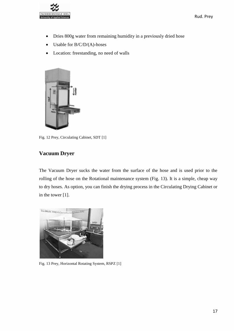
Dries 800g water from remaining humidity in a previously dried hose
Usable for B/C/D/(A)-hoses
Location: freestanding, no need of walls
Fig. 12 Prey, Circulating Cabinet, SDT [1]
Vacuum Dryer
The Vacuum Dryer sucks the water from the surface of the hose and is used prior to the
rolling of the hose on the Rotational maintenance system (Fig. 13). It is a simple, cheap way
to dry hoses. As option, you can finish the drying process in the Circulating Drying Cabinet or
in the tower [1].
Fig. 13 Prey, Horizontal Rotating System, RSPZ [1]

Rud. Prey
18
Horizontal Process Dryer (since 1991)
The Horizontal Process Dryer is a complete maintenance system with drying (Fig. 14) and it
is unique on the fire hose maintenance market. The maintenance process takes place in four
steps:
Hose is washed with high pressure water (up to 90bar) [13]
Hose is dried from the outside with warm dry pressurized air, very close to the
flattened hose
Hose is pressure tested with 12bar
Remove the water on the inside by blowing hot dry air through it (this also dries the
outside)
Technical data
Dimensions: 23,5/24,5 x 0,85m (Length x Height)
Hoses/drying process: up to 4
Location: freestanding on the floor or on wall brackets
Average energy use: 19kW
Usable for B/C/D/(A)-hoses
1 man to operate
Average performance: 12 / 16 B-hoses (depends on 2/4 hose machine) completely
maintained in one hour
Fig. 14 Prey, Horizontal Process Dryer, SPS-H [1]

Rud. Prey
19
4.2. Competitor’s Fire Hose Drying Systems
Automatic
hanging
system
Hose
drying
cabinet
Automatic
systems
Manual systems
Barth
Feuerwehrtechnik
Yes Yes No No
Bockermann
Feuerwehrtechnik
Yes Yes Hose drying fan Hose drying ring
Hafenrichter Yes Yes Hose drying
system AST/HST
No
Ziegler Yes Yes Modular hose car
unit MSP
Inclined system,
Manual live ring
Top Trock No Yes No No
Circul-Air Corp. No Yes No No
Table 4 Overview of Competitor's Systems
Automatic Hanging Systems
All the German companies offer their own fully automatic hanging systems to dry fire hoses.
In this kind of product, the customer needs to build a tower with a height about 25m. Here,
the drying can take 2 or 3 days without energy, using only outside air and windows for
ventilation. The drying time depends on the season, the material of the hoses and the tower
(fire department sometimes uses a system to heat the air) [10].
These systems need only one person to operate and have a good corrosion resistance. The
main difference between them is the hose adapters, which determine what kind of hoses can
be dried and the run time. Other that this, they are similar in capacity, weight, functions and
the power to work.

Rud. Prey
20
Barth offers the Bart-Lifturmatic III, with a capacity of 40-80 hoses for 5, and up to 20, rails
(Fig. 15). A unique quality of this system is found in the security. There is a wear-resistant
electro-mechanical security lock which is adjusted to the weight of the operator. This prevents
the operator from “hitting the roof” [4].
Fig. 15 Barth, Automatic Hanging System, Bart Lifurmatic III [4]
Bockermann has two automatic hanging systems: One is a ring system and the second is the
more usual rectangular slotted system. The first, “Hose Hanging System LKA-V” is only
compatible with B and C hoses [5].
Fig. 16 Bockermann, Automatic hanging System, LKA-V [5]
Technical data
Hanging opening at least 1,30 x 2,00m
Capacity max. 40 hoses
Weight of unequipped device approx. 200kg
Weight of equipped device approx. 1000kg
Ring diameter 1,05m
Electrical connection 400V 16A

Rud. Prey
21
Lift speed 5-22m/min. ED 60%
Corrosion protection: aluminum/enamel
The second, SBA, is a hanging system that is always adapted to the tower. It is compatible
with all types of hoses using many different adapters. The selling point of Bockermann is an
ergonomical and a friendly design that provides a high level of comfort for operators.
Fig. 17 Bockermann, Different Adapters for Hose hanging System SBA
Hafenrichter also produces two hanging systems: the SAH and the SRS. Both of these
products have the same characteristics.
Technical Data
Connected load: 2,9kW
Electrical connection: 380 V, 3 phases
Protective equipment: residual current circuit breaker / IP 54
Rated Power: 1,7kW
Bearing load of the chain tension: 125kg
Lifting speed: variable 20 – 2m/min
Capacity: between 44 and 60 hoses.
Dimensions: 1,25 x 2,75m (Width x Length), Width depends of tower dimensions
Necessary cross section of the tower: 1,4 x 2,8m (Width x Length), Width depends of
tower dimensions
Weight (charged): approx. 2750kg
The difference between the SAH and the SRS are the adapters. The SAH does not use
adapters. Therefore, the capacity of the SAH is lower with typically only 7 tracks, whereas,
the SRS can bear 60 hoses in a classic tower.

Rud. Prey
22
Fig. 18 Hafenrichter, Hanging system SAH without adapters [14]
Ziegler produces the following 3 hanging systems:
Hose suspension VSV-LB
Hose suspension VSV-C
Semi Automatic Live ring
Both systems, the VSV-LB and VSV-C, have the same common functions. They differ by
their systems and their adapters. Both can bear a maximum (depending of the tower) of 120
hoses, for all kind of hoses and couplings. Safety, speed and possibility to arrange the hoses in
different order are the main selling points of Ziegler.
Fig. 19 Ziegler, Hose Hanging System VSV-C Fig. 20 Ziegler, Hose Hanging System VSV-LB
The VSV-C can be bought for 40, 80 or 120 hoses. On the contrary, the VSV-LB adapts to
the size of tower, for a maximum of 120 hoses. Two different “double suspensions disk” are
available:

Rud. Prey
23
Fig. 21 Ziegler, Adapter for VSV-C Fig. 22 Ziegler, Adapter for VSV-LB
The third hanging system of Ziegler, the semi automatic live ring, is different than the other
systems because the forward movement of the chariot, for suspending and removing the hoses
from the hose suspension ring, is actuated manually via a control lever with a cable pull.
Other movements are automatic with the operator using the control board (from the floor of
the tower) to load hoses or rotate the ring [3].
Fig. 23 Ziegler, Semi Automatic Ring for 20 Hoses, HDK 20 [3]
Ziegler sells four kinds of this product (Weight approx.200kg):
HDK20 for 20 hoses (1,8x1,0x0,7m)
HDK30 for 30 hoses (2,2x1,3x0,7m)
HDK40 for 40 hoses (2,5x1,65x0,7m)
HDK20A for 20 hoses of size A (1,9x1,1x0,7m)

Rud. Prey
24
Drying Cabinet
All the competitors of Prey make a drying cabinet, which is the second most common drying
system in fire departments after the use of air. It too is a basic system because it is composed
of a cabinet, a heater, shelves for the hoses, and often a fan to circulate the heat. With many of
these dryers, it is possible to use it for clothes or as a room heater with the doors open as well.
Also, it is possible to add fixed rollers to make the system more mobile.
The Barth cabinet is distinguished by the hose carrying basket, which simplifies the load and
the storage of hoses (Fig. 25). In addition, it‟s possible to put a ventilation system on the
cabinet to transport the humid air out of the building [4].
Fig. 24 Barth, Drying Cabinet [4]
Specifications
For hoses up to a diameter of 110mm, 20m length
Capacity: 8 shelves so 16 hoses max
Drying Time: between 5 and 8 hours
Dimensions: 1,98 x1,0 x 0,86m (H x W x D)
Electrical Connection: 230V - 3,3kW with time switch

Rud. Prey
25
Fig. 25 Barth, Hose Carrying Basket
The Bockermann cabinet, contrary of Barth cabinet, has a fan and a control thermostat that
monitors the temperature. Heating is done with a pressure ventilator and a radiator that is
installed on the cabinet. Also, the STS 821 has a transparent acrylic glass door, which useful
when checking the drying progress [5].
Fig. 26 Bockermann, Drying Cabinet, STS 821 [5]
Specifications
Capacity: 10 shelves
Dimensions: 2,04 x 1,25 x 1,25m (H x W x D)
Air delivery: 45m3/min.
Heating power: 6kW
Weight: approx. 250kg
The hose drying cabinet from Ziegler is equipped with a fan and a thermostat. The
temperature of the air flow inside does not exceed 38°C [3].

Rud. Prey
26
Fig. 27 Ziegler, Drying Cabinet, STS 10-W [3]
Specification
Capacity: 10 shelves
Dimensions: 2,11 x 1,34 x 1,15m (H x W x D)
Weight:190kg
Drying time: 3 to 4 hours
Electrical connection: 6kW - 400V/16A
The drying cabinet system from Circul-Air Corp. has capacity to dry 10 fire hoses, each one
in a removable galvanized steel shelf. To dry this number of fire hoses, the machine must
operate for 12hours. A timer then shuts down the dryer automatically. It uses less energy and
never damages the hose.
It uses fresh air that is drawn over 1kW heater strips (thermostatically controlled) to dry the
hoses. An axial fan mounted on the top moves the air. The variable dryer settings can
maintain an optimum hose drying temperature. As an alternative to the warm air settings
available, the ambient air setting can dry without heat. [8]

Rud. Prey
27
Fig. 28 Circul-Air-Corp., Drying Cabinet [8]
Finally, there is the drying cabinet from Top Trock GF900, which can dry between 8 and 16
fire hoses. It works with a warm-air blower operating at 230V approx. 1,3kW. It has a
warranty of either 2 years or 5000 operational hours. Furthermore, it complies with the device
safety regulations. The cabinet is made from zinc-plated sheet steel, powder-coated baked,
with 8 extendable stainless steel grids. The rails are made from zinc and the air distribution
pipes from stainless steel. It has a valve system to choose either inside or outside drying, and
a lateral external junction for inside drying of the hoses. Its dimensions are: 0,95 x 1,95/2,13 x
0,6m (W x H x D) [7].
Manual Hanging System from Bockermann and Ziegler
Air is used to dry for the following systems, therefore a simple system to hang the hoses is all
that is needed. These systems are manually operated, requiring the operator to load the hoses
and often lift the system. It does not necessarily need to be used with tower, and is most often
used in a high building or outside.
Fig. 29 Bockermann, Slewing Ring, STK 510/20 [5]

Rud. Prey
28
Specifications
For B and C hoses
Weight for 16 hoses: 11kg
Weight for 20 hoses: 14kg
To complete the range, Bockermann also sells two electric chain hoists or pulleys, but these
products are only accessories and not actual drying systems [5].
The manual live ring from Ziegler, which is basically HDK system without control board, is
operated from the floor of the tower by pulling a cable to raise the hoses [3].
Fig. 30 Ziegler, Manual Live Ring, MDK 20 [3]
As with the HDK system, Ziegler offers several options with the manual system (Weight
approx. 150kg):
MDK20 for 20 hoses: 1,8 x 1,0 x 0,5m
MDK30 for 30 hoses: 2,2 x 1,3 x 0,5m
MDK20A for 20 hoses of size A: 2,2 x 1,3 x 0,5m
Fig. 31 Ziegler, Inclined Drying System for 20 Hoses

Rud. Prey
29
Ziegler also offers an ingenious inclined drying system (for 10, 16 or 20 hoses) for fire
departments without tower.
Automatic Drying System from Ziegler
This system is not only a drying system but complete hose care system, where the hose is
washed, tested, and dried without intervention of the operator [3]. For inside drying, they use
a patented ball covered with fibers to clean and dry [15].
Fig. 32 Ziegler, Modular Hose Care Unit, MSP [3]
Specification
Floor Surface: 12m²
Capacity: 8-9 hoses per hour
For A/B/C/D hoses
Hose Drying Fan from Bockermann
Another original system, from Bockermann, is this fan (Fig. 33). It blows warn air inside the
hose, with the temperature being controlled by a thermostat. It can be used for hoses of the
size B, C, or D. With a maximum heating power of 6kW, four synthetic hoses can be dried in
approximately 2 hours [5].

Rud. Prey
30
Fig. 33 Bockermann, Hose Drying Fan [5]
Three designs are available:
One Hose Connection (TG 810):
o Motor: 380V - 0,37kW
o Total pressure difference: 1,6kPa
o Flow volume: 0,08m3/s
o Total heating power: 1,5kW
o Weight: approx. 38kg.
Two Hose Connection (TG811):
o Motor: 380V - 0,75kW
o Total pressure difference:1,6kPa
o Flow volume: 0,30m3/s
o Total heating power: 3kW
o Weight: approx. 50kg
Four Hose Connection (TG812):
o Motor: 380 Volt
o Total pressure difference: 2,0kPa
o Flow volume: 0,66m3/s
o Total heating power: 6kW
o Weight: approx. 65kg

Rud. Prey
31
Fig. 34 Bockermann, Four Hose Drying Fan, TG 812 [5]
Automatic Drying System from Hafenrichter
Hafenrichter produces a system similar to a drying cabinet, yet more sophisticated. Two
systems are available: a fully automatic AST and a semi automatic HST [6]. We do not have
precise information about how hoses are dried, but it takes place with a hot air current [15].
Specifications of systems AST / HST
Electrical Connection: 4kW - 380V
Floor surface: approx. 4m²
Dimensions AST: approx. 1,98 x 1,12 x 0,98m (H x W x D)
Dimensions HST: approx. 1,98 x 1,95 x 0,98m (H x W x D)
Weight: approx. 450kg
For Hoses B/ C/(A)
Capacity / h: approx. 10 B-hoses
Cost per hose: approx. 0,10€
Fig. 35 Hafenrichter, Semi Automatic System, HST [6]

Rud. Prey
32
5. Decision Matrix
In order to determine the best solution to the project, it was necessary to develop a set of
decision criteria to use as a basis for comparing the current drying processes and any designed
processes in the future. In addition, this will permit us to determine which ideas in the market
are interesting to inspire us. An important remark is that this matrix is for the German market,
German fire departments, and German companies. The criteria are a combination of product
specifications and performance, specific to the drying process and containing the essential
factors. Along with this, a method was also developed to evaluate each drying process. A
rating of 1-10 is given to each criteria point and, based on the weight of each criteria category,
a rating for each product was determined. It provides information regarding the positive and
negative aspects of each drying method. The rating can then be used to compare each method
and, more importantly, assess which technology is the best. A decision matrix was created in
Microsoft Excel to combine the criteria and method. Below is the criteria being used to
evaluate the drying processes are described.
5.1. Compatibility
It is important to be aware of what drying methods work with what hoses. As fire-fighters use
several types and sizes of hoses, knowledge of whether the hose will be compatible with the
process is needed. Usual hoses in Germany are 20m-A-hoses, 20m-B-hoses, 35m-B-hoses and
15m-C-hoses. But 20m-B-hose and 15m-C-hose are excluded of Matrix because they are
essential, and all systems work with these types; without this compatibility, the system will
not sell.
5.2. Cost
The cost (in €) of drying will be viewed from the perspective of the consumer. Three areas
will be included in the category of cost:

Rud. Prey
33
- Machine Cost (initial purchase)
- Operation Costs (drying 1 hose)
- Maintenance Costs (once/year)
The cost of implementing a new technology into a company is of great significance and thus,
this section of the criteria is broad to offer a more complete evaluation of each product.
5.3. Design/Ergonomics
It is important to consider the functionality of the drying system. This section will examine
the areas considered significant to the consumer:
- Aesthetics
- Comfort
- Ease of Operation
- Safety
The appearance of the machine (including the infrastructure required of it), the comfort of the
operator, the amount of technical knowledge or training needed to operate the machine, and
the safety when operating the machine are all necessary points to consider when comparing
technologies. It is a very subjective area when gathering this data.
5.4. Energy
In this section, the amount of energy, required of the machine, to dry 1 hose (chosen standard)
will be considered. The energy use will be specific to the process of drying and will exclude
energy needed for other hose maintenance processes, which are often in combination with the
drying process. This is important from an environmental and resource usage perspective. It
will also be closely related to the cost of operation for each method. We used the unit,
[kWh/hose],to compare.

Rud. Prey
34
5.5. Noise
The loudness of the drying system was difficult to evaluate for all known technologies
without a personal experience, but it is important in this category to know what systems may
cause hearing loss, or require ear protection. The data for noise measurements was used as
comparison, where all measurements were taken with 1 meter distance from the source and
given units of [dB(A)].
5.6. Space
The size, in meters, of the drying system and the space that it requires to dry the fire hoses is
important for the consumer to know. In fire departments space is often limited; therefore a
drying system with less space demands may likely be a better choice. A better rating will be
given to a system that uses less space. We consider only floor space, because the height will
never impact the choice, as all of them can enter a normal building.
5.7. Speed
The rate at which hoses can be dried will be evaluated in this category. The amount of time to
dry 1 hose (in [min] for a 20m B hose) for each system will be used as grounds for
comparison.
We filled in the matrix with different systems decided upon with Mr. Prey. We did not
compare the hanging system, as it makes no sense. We are aware that the hanging system is
the best way to dry fire hose. It is the first consideration of fire departments and the best
solution if a tower is available. To fill in the matrix we used differences sources and
assumptions later discussed and cited in the report.
Rud. Prey
35
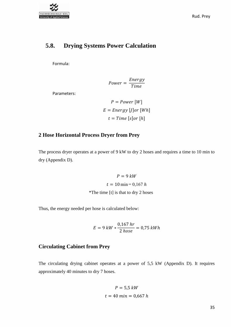
5.8. Drying Systems Power Calculation
Formula:
Parameters:
2 Hose Horizontal Process Dryer from Prey
The process dryer operates at a power of 9 kW to dry 2 hoses and requires a time to 10 min to
dry (Appendix D).
min 0,
*The time [t] is that to dry 2 hoses
Thus, the energy needed per hose is calculated below:
Circulating Cabinet from Prey
The circulating drying cabinet operates at a power of 5,5 kW (Appendix D). It requires
approximately 40 minutes to dry 7 hoses.

Rud. Prey
36
*The time [t] is that to dry 7 hoses
Therefore, the energy needed to dry one hose is:
Automatic Cabinet from Hafenrichter
The AST from Hafenrichter operates with a power of 4 kW during the drying process. It is
said to be able to dry 10 hoses in one hour [6].
*The time (t) is that to dry 10 hoses
Thus, the energy needed to dry one hose is:
Ziegler Automatic System
We assume that the power of the vertical rotating system from Ziegler is 9,3kW the same than
the rotating system from prey (Appendix D). In addition, the speed to dry is 10 B hoses per
hour [3].
*The time (t) is that to dry 10 hoses
Thus, the energy needed to dry one hose is:
Rud. Prey
37
5.9. The Decision Matrix
Matrix is adapted to report concerning the format
and everything!

Rud. Prey
38
5.10. Conclusion about the Matrix
As you can see in the matrix, the results are not satisfactory; many things are assumed,
estimated, or subjective. The main aim of the matrix was compare our suggestion with the
systems of the market, but several factors made that impossible.
First of all, this project is only considering the drying system, but most of the machines being
used are not only to dry. Thus, it becomes difficult to compare the drying methods. Secondly,
companies do not openly display the specific characteristics and performance of their
products, which makes it difficult to precisely rate certain aspect of some systems. In
addition, many systems are similar because the principles behind the technologies are copied,
and therefore the interest is lessened. Finally, our level of investigation was limited and
accurate data was unable to be collected to discover all prices, the comfort, and the ease of
operation. The matrix, at the beginning of the project, was useful and our primary focus, but
as we progressed it became clear that such a complex comparison would be impossible and
the information gathered does not help us on our project.

Rud. Prey
39
6. Thermodynamics
There exist three ways to transform fluids to vapor: evaporation / vaporization, sublimation
and overheated vapor (Fig. 36).
First, it is important to explain the difference between evaporation and vaporization.
Evaporation is the changing from fluid to vapor below the boiling point, whereas vaporization
takes place at this temperature. Above this temperature, every fluid vapor is produced from
evaporation. The pressure increases until a certain temperature dependent maximum value,
the so called saturation vapor pressure, is reached. If this pressure is reached, the vapor and
the fluid are in equilibrium (this means the pressure of fluid and vapor are the same and thus,
the vapor is saturated). Until this maximal vapor pressure the fluid is able to evaporate. To
increase the evaporation rate, you must increase the volume or the temperature of the vapor,
or remove the saturated vapor from the surface. With these methods a layer of unsaturation is
kept, allowing more fluid to evaporate. If too little fluid is given at a certain temperature,
vapor does not reach the saturation vapor pressure and thus, the vapor remains unsaturated
[16].
For drying this implies that as long as the vapor layer stays unsaturated it is possible to dry.
This means, that you need to add air current and / or heat to keep the drying process running.
Without these additional methods drying takes much more time because the saturated vapor
needs to diffuse to the surrounding unsaturated air.
Another possibility for transforming a fluid into vapor is sublimation which takes place by
“looping” through the solid state of aggregation. The process is given in two steps. At first,
the pressure and temperature are lowered just below the triple point of water (0,01°C,
0,0061bar) [17] to freeze the water. The temperature is then increased a little as the pressure
remains. The ice becomes vapor without passing through the liquid phase. As a drying
technology this refers to the process of freeze drying or lyophilization.
The third way for achieving vapor is by overheating. Like sublimation, you have two steps to
transform fluid into vapor. First, you increase the temperature and pressure to the critical
point of water (373,95°C, 220,6bar) [17]. Now, the change-over from fluid to vapor is
constant, meaning that there is no separation of the liquid and the gaseous phase. Next, you

Rud. Prey
40
slowly decrease the pressure to ambient pressure. The vapor in the mixture expands and thus,
the vapor pressure decreases allowing more water to evaporate. This method is known as
supercritical drying [17] [18].
Fig. 36 Phase Diagram of Water [12]

Rud. Prey
41
7. Drying Methods
7.1. Mechanical Drying Technologies [19]
Before discussing mechanical drying methods, we must state that these kinds of dryers are
actually not dryers, because instead of evaporating the humidity of materials, they only
remove the water.
Several mechanical methods are available to reduce the amount of water in materials. We will
speak about the four most common techniques which are: air knives, squeezing, suction, and
centrifugation.
The technique selected for drying is influenced by the type of material, the quantity of the
material that is going to be processed, and how the process is going to be used. For example,
in the case of the textile industry, many delicate fabrics are damaged by being squeezed
between two rollers, or damaged by spinning in a centrifuge. Thus, since the suction through
vacuum slots cause less damage, it is most suitable, and often used for drying delicate fabrics.
Another example is that centrifugation is normally limited to batch processes.
Air Knives
In an air knives machine the natural or heated air flows with high pressure through a very thin
nozzle and blows away the surface water. A smoother, less porous surface will allow more
water to be removed using this technique. The effectiveness of this method is greater when
the nozzle is closer to the surface of the material being dried. However, this is not a proper
drying technology, due to the fact that it only blows away the water instead of evaporating it.
Squeezing
It consists of removing the water from a wet material by applying pressure on two opposite
sides of the material to dry and moving it in the opposite direction of the material.

Rud. Prey
42
Fig. 37 Principle of Squeezing Rolls
Suction
The principle of suction involves getting the water out of the wet material by changing the
pressure.
Centrifugation
Normally, centrifugation is used for separating different phases or ingredients in fluids. The
process of centrifugation achieves this separation by means of the accelerated gravitational
force generated by a rapid rotation.
In relation to the aim of removing water from a textile, the material is spun in order to expel
the water from it. The centrifugal force during the spinning process drives the heavier
substances to the outer edge of the radius. Thus, after a while you will receive separated
phases [20].
There are a lot of applications of mechanical drying methods, but the most important and
frequently used are:
Textile industry
Paper industry
Specific to the use of air knives:
Drying a car at the end of a car wash
Drying bottles and cans after filling or washing
Rud. Prey
43
Specific to the use of centrifugation:
Solutions
Pharmaceutical and medical Industry
Advantages
Cheap technology because they do not require the use of air or water
Simple mechanisms
Disadvantages
Most of the products dried by these methods are not totally dried
Sometimes air convection is needed to dry completely
Possibility of deforming the product
Too much noise
Specific disadvantage of using air knives:
Additional need of a compressor
Currently, air knives, squeezing, and suction methods are used to dry fire hoses. Rud. Prey
GmbH & Co. KG has experimented with these methods for fire hoses, but the results showed
that air knives and squeezing was not as efficient as drying by suction. (Appendix D)
Due to the inconvenience that these methods do not dry totally, they are used in the pre-
drying process, in order to remove most of the water from the hose before it is dried
completely with another technology.
Centrifugation could theoretically work to dry fire hoses because the fire hose is made of
textile fibers, and however a large force would be needed to rotate the hose. Regardless of the
axis chosen to rotate the hose around, this method would be unsuccessful in a process system
to dry fire hoses.
Rud. Prey
44
7.2. Convection
Natural Air Free Convection
The free convection of natural (i.e. unconditioned) air happens every day in our weather
systems. It is the movement due to differences in temperature or pressure. As the air gets
warmer, it rises and cooler air replaces it. The same happens with pressure differences. The
air flows from high to low pressure areas, and the “empty” space of the higher pressure area is
filled up with new air. In both cases an air circulation, called wind, is generated. This wind,
however minimal, is enough to blow away the layer of water saturated air directly over the
surface being dried. The evaporating rate, with respect to the partial pressure difference of
water to air, increases. This means that more water can evaporate from the material in a
defined time.
Applications
Hanging clothes on a clothesline on a windless day or indoor
Drying food outdoors on fences or similar
Tower for fire hoses
This drying technology has been used for drying fire hoses for a very long time. It is the
easiest way to dry, because you do not need additional devices to induce drying. This is the
only disadvantage of free convection: You need more time to dry than by using an artificial
source of heat and/or wind.
Natural Air (forced convection)
Forced convection is essentially the same principle as free convection, but due to the forced
air current the saturated layer is removed faster, allowing more water can evaporate.
Applications
Hanging clothes outdoor on a windy day
Tower for fire hoses with fan on the ground
Rud. Prey
45
Shown in the examples for application, this is a common method in use to dry fire hoses. A
disadvantage is the additional fan required to make this condition, which consumes energy
and produces noise.
Hot Air (free convection)
The process of free convection with hot air is similar to that of free convection with natural
air. Instead of air at ambient temperature, artificially heated air is used. Thus, the temperature
of the material and the water increases, producing a faster rate of evaporation.
Applications
Putting wet clothes on radiator
Drying chamber for food (fruits, corn, herbs, etc.)
Drying cabinet without fan for fire hoses
As you can see above, free convection with hot air is an easy and common way to dry fire
hoses. It is faster than with natural air, but because of the heating, you need more energy to
dry.
Hot Air (forced convection)
Hot air with forced convection is a “double improvement” of natural air with free convection.
On one hand you have the additional heat to increase the temperature of the water; on the
other hand you have the forced convection which blows away the surface layer thus,
increasing the rate at which the water can evaporate.
Applications
Laundry dryer
Food and textile industry
Circulating Cabinet of Prey
Horizontal Process Dryer of Prey
Drying cabinet with heater and fan

Rud. Prey
46
Of these examples you can see that this method is a very common way of drying; be it in
industrial processes, households, or for fire hoses. An advantage of this method is that the
drying time decreases enormously. But for this advantage, you have to accept the costs for
energy and additional devices, such as fans and heaters.
7.3. Conduction
Drying with conduction is an indirect drying method, because the heat is transferred to the
wet solid through a retaining wall. The speed of drying depends on the contact established
between the wet material and hot surface, the time of contact, and the temperature of the hot
surface.
In contrast with indirect drying, a larger quantity of hot air is necessary for "direct drying" in
order to obtain the necessary evaporation. In indirect drying, heat is transferred by, for
example, steam to the wall, which then transfers the heat to the material on the other side of
the wall. All the heat transferred by the wall is used to dry the product and it does not leave
the system like hot air that needs to leave through ventilation, thus making indirect drying a
much more efficient process than direct drying.
Rotary Drum Dryer
Rotary dryers are horizontal cylindrical drums made of metal outer walls on which steam or
hot water flows to heat the surface. The material to be dried is put inside, and when it comes
in contact with the hot walls of the drum, its temperature increases and its humidity
evaporates. The material is stirred by rotating the drum. A series of rotating blades attached to
a horizontal central axis are used to remove and constantly renew the surface evaporation and
thus increase the drying time. Steam generated by evaporating the humidity passes through an
opening in the top where is travels to a condenser [21].
Applications
Foods
Solutions, suspensions and pastas

Rud. Prey
47
Advantages
Less expensive than convection dryers
Disadvantages
It is applicable for a limited amount of products (small products and solutions)
This method could not work to dry fire hoses because of the shape of the machine. The
rotating blades would not permit the drying of a fire hose inside the machine. Such a process
would not be logical considering the size of a fire hose. It is only used to dry either solutions
or small piece of food like seeds.
Shelf Dryer
A shelf dryer is a cabinet with dishes or shelves inside, made of cast iron or steel, into which
either hot water or steam flows, providing the necessary heat to evaporate the water of the wet
material that is resting on these shelves. Thus, the heat is conducted up through the solid
metal shelves. After this, the steam generated by the drying usually goes to a condenser.
Fig. 38 Principle of a Shelf Dryer [22]
Applications
Textile industry

Rud. Prey
48
Wood
Foods
Advantages
Less expensive than the convection dryers
Disadvantages
Drying is not uniform for big products
It is not possible to dry fire hoses with this technology because the hose would not be dried in
a uniform manner. The area in contact with the shelf would likely be the only part which
dries, and if time allowed for the heat to transfer to the entire surface of the hose, much
energy would be wasted.
Hot Cylinders
This kind of indirect dryer works using the same principle: the transfer of heat to the material
directly by a hot surface. It is made of a determined number of cylinders, into which either
steam or warm water flows. In this case, the evaporation of water that occurs on the surface of
the material to dry, escapes directly to the atmosphere without the need of a condenser in the
machine.

Rud. Prey
49
Fig. 39 Principle of heating Cylinders with Steam [22]
In main industries, like in paper or textile industries, the hot cylinders are used as rolls in the
pressing process.
Applications
Paper industry
Textile industry
Advantages
Less expensive than the convection dryers
Can work in open space
Disadvantages
Possibility to burn the material because of the direct contact
Dry by Cylinder Heated by Electric Induction
One particular and recent technology to heat the hot cylinders is to use electromagnetic
induction. This technology arose because of the need to decrease the energy used to heat the

Rud. Prey
50
cylinders with the traditional drying processes (hot water or steam). Induction heating is a
method for continuous and rapid heat.
Fig. 40 Principle of Drying by Induction heated Cylinders [23]
The process involves contacting the wet fabric in motion with a rotating hollow metal
cylinder whose surface is heated by electrical induction. The process uses electrical currents
induced in the material to produce heat. The basic elements of an induction heating system are
an AC generator, an induction coil, and the material will be heated or treated. The generator
sends alternating current through the coil, generating a magnetic field. When metal piece is
inside the coil, the magnetic field induces currents to this piece, generating precise amounts of
clean heat and without any contact between the coil and it [23].
Applications
The same applications than the traditional technologies to heat the cylinders
Advantages
Less consumption of energy than the traditional technologies to heat the cylinders
Disadvantages
The same disadvantages as the traditionally technologies to heat the cylinders
Rud. Prey
51
This technology could work to dry fire hoses. The size, the shape, and the materials of the
products that are dried by hot cylinders are similar to those of the fire hoses. Thus, we will
investigate this technology by making some experiments.
Drying under Vacuum
There is a variable of some of the drying methods that consists of drying the materials in the
same way, but in a hermetic place with the vacuum inside to dry the material faster. The
vacuum is made by a mechanical pump.
So far, this relatively new method works in the indirect dryers like a rotary drum dryer and a
shelf dryer. Also, it can work in a microwave machine dryer. These methods, that can operate
under vacuum, at pressures below atmospheric pressure, allow the product to be dried at
lower temperatures, in the absence of oxygen. They are able to reduce the boiling point of the
water and then quickly convert the humidity into steam.
The air does not pass through or recirculate in these machines, and therefore the steam is
collected in order to be condensed elsewhere.
There is a wide range of applications for this method including, damage prevention to heat-
sensitive product components, or evaporation of solvents at low temperatures. Also, foods can
benefit from such careful treatment. The evaporation takes place within a few seconds without
the risk of oxidation. In this way, the enzymes and proteins in the food are preserved and new
protein formation is prevented. Chemical products, too, can be used in a dryer from a vacuum
process and undergo the drying treatment [21].
Applications
All heat-sensitive products
Foods
Chemical products
Advantages
Can dry at lower temperature

Rud. Prey
52
Disadvantages
So expensive to obtain the vacuum
Too much difficulty to build the machine
7.4. Radiation Drying Methods
We will start with some information about radiation and finish with different drying
technologies which use radiation methods.
Wave Definition
An electromagnetic wave is similar to a particle flowing without mass, as photons. They
move at the speed of light inside a vacuum (c0). A wave is characterized by the distance it
covers in one oscillation: its wavelength (λ) or its frequency (f). Below is the formula which
links these physical quantities.
Electromagnetic Spectrum
According to the wave definition we can classify waves in different categories, as we can see
below (but these limits are more or less arbitrary and depend of sources):

Rud. Prey
53
Fig. 41 Electromagnetic Spectrum [24]
Energy information
All these radiations go through air without sensible energy loss; the energy is absorbed only
by matter, so losses are less important than with usual methods. In addition, the power can be
focused on some parts of the receiver and the regulation is instantaneous. To finish, the
energy of a wave depends of its frequency, thus the more frequency requires more energy.
Ultraviolet
In this section we will define what ultraviolet radiation is, see different applications, and
conclude to see if it is possible for it to be adapted to dry fire hoses. We will develop only the
characteristics of ultraviolet in reference to drying and not to other applications.
If we look at the electromagnetic spectrum we see that ultraviolet waves have wavelengths
between 100nm and 400nm. Three types of ultraviolet light exist: C ultraviolet (from 100nm
to 280nm), B ultraviolet (280nm to 315nm) and A ultraviolet (315nm to 400nm). The power
of a wave increases when its wavelength decreases, thus C rays are the most powerful.
Around us, ultraviolet rays are created by the sun and can cross the atmosphere or clouds (C
ultraviolet is stopped by the ozone layer). In addition, ultraviolet follow rules of optic laws
(can be reflected by a mirror for example).
About energy, ultraviolet is the most powerful radiation and it acts directly on electrons.
Indeed, an ultraviolet ray can remove an electron from the external layer of electrons and thus
drives a chemical reaction. It is the reason why ultraviolet light dries by polymerization.
For humans, ultraviolet rays produce the necessary, Vitamin D, when they contact the skin.
However, overexposure can lead accelerated aging in the skin and sunburn. They can also be
the cause of cancer (principally B ultraviolet) and they have an impact on eyes [25].

Rud. Prey
54
Ultraviolet Lamp
Most of ultraviolet sources are lamps (principally). The gas inside drive the principal
wavelength of rays created. Thus, from the mercury, we get a majority of C ultraviolet; with
halogens, we get principally A and B ultraviolet. To finish the size of such lamps is important;
around 10mm to 2m is possible.
Fig. 42 UV-Lamp “Starfire” from Phoseon (Oregon, USA) [26]
Specifications
Size: 75x20mm
Spectrum: 395nm
Power: 4W/cm²
The power of lamp is not enough to determine the energy received because the distance from
the source drives this energy. We can find in the market products ranging from 7µW/cm² to
300W/cm² [27].
Drying Applications
Printing sectors for dry ink
Manicure to dry nail varnish
Ultraviolet drying systems present the best advantage of being cheap and particularly efficient
for products sensible to polymerization [28].
We cannot envision a method to dry a fire hose with ultraviolet radiation because of the
principle of this drying method.

Rud. Prey
55
Infrared
Infrared radiation refers to wavelengths between 1nm to 730nm. All warm matter
(temperature higher to 0°K) emits an amount infrared radiation (principle of infrared cameras)
which is a carrier of calorific energy. Thus, infrared has no influence to the human body. On
the matter, infrared radiation has less energy than ultraviolet so it creates an electronic
agitation around the atom, which in turn, creates heat. We distinguish between three kinds of
infrared radiation: short-wavelength (from 0,73 µm to 2µm), mid-wavelength (from 2µm to
4µm) and long-wavelength (from 4µm to 10mm). Short-wavelength is the most penetrating
and is able to travel through transparent glass.
To create infrared radiation, we use a heater source where the temperature is changed in order
to change the wavelength of the radiation. This simple method of creating infrared radiation is
at the origin of the number of different technologies, and therefore with industrial application,
a long case study must be performed. We are presenting an overview of each of them. Two
different transmitters are used: electric transmitters and gas transmitters [29] .
Electric Transmitter
This kind of transmitter works by the Joule effect and thus, they are easy to regulate. To
create short-wavelength infrared radiation we need a high temperature, therefore, lamps with
tungsten filament are used to reach a temperature around 1500°C-2000°C.
To create mid-wavelength infrared radiation the temperature doesn‟t need to be high, but the
principle remains the same. There are many ways to do this. Silica tubes with filament on the
inside, used as a resistor, can reach temperature of 800°C-1200°C. Stainless-steel tubes (still
with an intern resistor) can be temperatures between 700°C and 800°C. We can also find
transmitters using ceramic materials.
Gas Transmitter
In this case the principle is different than electric transmission. A wall is heated by
combustion and the radiation is released from the radiant surface (Fig. 43). They create mid
and long-wavelengths which correspond to temperatures between 500°C and 1200°C.

Rud. Prey
56
Fig. 43 Principle of a Gas Transmitter [30]
For this technology, systems differ by the burner which can be ceramic, or metallic, but the
aim is to always keep the most constant possible temperature [30] [31].
Applications
Infrared systems are used in many sectors:
Agricultural
Food
Glass
Medical
Paint
Pharmaceutical
Paper
Plastics
Rubber
Textile
This drying method is efficient (like all the radiation methods) because of its effect directly on
the matter. In addition, infrared is easy to manipulate (geometric optic laws) and is not
harmful to people. On the contrary, this technology is not common and requires knowledge to
Rud. Prey
57
use it effectively. The heating success depends on matching the emitted wavelength with the
absorption spectrum of the material to be heated and its shape. Lastly, the efficiency depends
on the relative position (distance and angle) of the emitter and the receiver.
This can pose minor problems to drying fire hoses, but it could be adapted. In industry, there
exist infrared radiation technologies to dry textile.
Microwaves
We are going to present the principle of Microwave technology, some applications of this
method for drying, and some examples of machines used in different industries. We will
develop only microwave information concerning ovens and not that concerning radar or other
applications.
Microwaves range from 300GHz to 300MHz theoretically. Microwave ovens used in industry
or as a household appliance operate with a frequency of 2.45GHz, which corresponds to a
wavelength of approximately 10cm. Some of them use 915MHz (cf table), for big power.
When a microwave goes through matter, it is able to move molecules which are sensitive to
electric fields. A molecule that is very sensitive to this perturbation is the water molecule,
among others. The molecule is “rushed” by the electric field and starts to run around itself
with high speed. During the movement, the molecule shocks molecules around it. In the
molecular world, movement is heat and thus, microwaves are able to heat matter.
Metallic objects reflect microwaves, and in each angular or pointed corner of the metal, some
gradients of electric field are created. These gradients cause electric arc [24].
For humans, microwaves are dangerous because of the elevation of the temperature on the
eyes in particular.
MW Oven Technology
A power transformer changes the alternating current into high direct current to supply the
magnetron. The magnetron changes the electric energy into electromagnetic energy. Created
waves go through the waves guide to reach the heating chamber. Waves reach the object
directly or indirectly (by walls). Below are two figures of a domestic microwave oven to show

Rud. Prey
58
the components and operation. The same principle works in an industrial microwave oven
[32].
1: Case
2: Power transformer
3: Fan for diffusion
4: Magnetron
5: Waves guide
6: Rotative reflector
7: Metallic reflector
8: Heating chamber
9: Rotative plate
Fig. 45 Operation of a MW Oven [32]
Fig. 44 Components of a MW Oven [32]

Rud. Prey
59
The magnetron has not a 100% output, below characteristics of different magnetrons.
Generator Power [kW] Frequency [GHz] Power Output [%]
Domestic Magnetron 0,5-1 2,45 60-70
Industrial Magnetron 5-15 2,45 60-70
Industrial Magnetron 50 0,915 60-70
Table 5 Power and Output of MW Ovens [24]
Drying Applications
Microwave drying systems (which appeared soon after the Second World War) can be found
in all industrial sectors because of positive points that we will develop later:
Food-processing industry
Chemical
Paper-making industry
Pharmaceutical industry
Textile
Printing
Building
Microwave drying presents advantages over conventional, thermal heating/drying methods.
First of all, the process speed is increased and the energy conversion is efficient. In a
microwave drying system, energy couples directly to the material being heated. It is not
wasted in heating the air, the walls of the oven, conveyors, etc. Also the energy source is not
hot and thus, savings in plant cooling may be realized. In addition, a good and rapid process
control is possible (in a domestic oven the time to switch off is 10s after push the button)
and floor space requirements are less (it is due to a more rapid heating by microwave energy).
To finish, microwave drying can be conveniently combined with other drying methods and
this often occurs (such as hot air drying, freeze-drying, vacuum drying, etc.). At the same
time, microwave drying presents some significant disadvantages to be considered. The drying
is unequal because it depends directly on the water quantity in the product. An unequal
distribution of water in the product would result in unequal heating. Also, it can be dangerous

Rud. Prey
60
to humans, so a good maintenance is required. And to finish, the product must not contain any
metal (this is important in the case of fire hoses) [33].
To conclude, the method of microwave drying can be interesting to dry hoses and is an
avenue of research for the future.
Radiofrequency
Radio frequency radiation (RF) is a rate of oscillation in the range of 3Hz to 300GHz. Such
dryers are working in a high frequency area, which is between 30-300MHz.
In a radio frequency drying system the RF generator creates an alternating electric field
between negative and positive electrodes. The wet material is conveyed between these
electrodes where the alternating energy causes polar molecules in the water to continuously
re-orient them to face opposite poles, much like the way magnets would move in an
alternating magnetic field. We find a similar principle in the microwave, but the frequency
changes and the method of creating the magnetic field too.
Consequences on the human body are the same as microwaves.
Radio Frequency Dryer
A radio frequency dryer (Fig. 46) is mainly made up of a generator which, being fed with
electricity, produces the RF electromagnetic field. In addition, a drying chamber (a closed
cabinet for batch-wise processes or a tunnel for continuous processes) is fitted with the
electrodes to deliver the RF energy to the product.
Fig. 46 Description of a Radio Frequency Drying System with a Product between the Electrodes

Rud. Prey
61
Applications
Textile
Glass
Ceramic
Paper
Radiofrequency presents same characteristics as microwaves, and because it directly affects
the water molecule, it can be controlled precisely. At the same time, the heat is generated only
where the water is and may produce irregular heating.
RF could be adapted for fire hoses drying technology, because this drying type is already
adapted to dry textile. For more information how it works with fire hoses is important to do
further investigations.
7.5. Chemical Drying Methods
The method of removing water from a material or substance by exposing it to a chemical is
readily used in both industry and the laboratory. The initial study of chemical drying methods
led to two main techniques used: solvents and drying agents (in particular inorganic salts).
This section will discuss these two methods and their applicability to fire hoses.
Solvents
When referring to a solvent in the case of drying, it can be described as a fluid, usually a
liquid that has the ability of dissolving other substances, without chemically changing the
solution. Both organic and inorganic solvents exist. The process of solvation usually occurs
when a polar solvent is used to dissolve an inorganic salt by surrounding the molecules of the
solute and interacting with them [34]. This method is rarely used as a method as a means of
removing water from the surface of an object. The amount of solvents that exist was far too
numerous for us to consider, and thus the use of acetone, because of its miscibility with water,
was the solvent of choice when discussing this method.

Rud. Prey
62
Application
Using solvents to dry, as needed for this project, is not an applicable science found in
industrial sectors. The use of solvents can be found primarily in paints and inks, where a fast
and even drying time is needed. They are also used as strong cleaners applied in the dry
cleaning process. However, the drying mentioned with paints, adhesives, inks, and rubber is
not referring to the removal of water from the product, but the evaporation of the solvent from
the solution[35].
Conclusion
Although, there is currently no method which distinctly uses solvents as a means of removing
water from the surface of a textile, it is still possible to imagine how such a method could
work with fire hoses. As mentioned, acetone is miscible with water, and therefore, if after the
hose was washed it was covered in a layer of acetone, it would be expected that the acetone
would mix and form a solution with the water, which would lower the temperature required to
remove the liquid from the surface. The advantages of solvents are numerous when used in
their current application methods, but the only advantage to using a solvent when drying a fire
hose would be the decreased energy needed to evaporate the solution from the surface. This
also, only works with solvents that are miscible with water, like acetone. If implemented into
a fire hose drying method, it would be wise to consider the greatest disadvantage of solvents
and that is flammability. If the solvent is not completely removed from the fire hose before it
is rolled up, it may become unsafe to use especially for fighting fires[36].
Drying Agents
Drying agents are typically insoluble, inorganic salts, which hydrate upon exposure to water.
The amount of water absorbed is depended on the molecular structure of the drying agent.
Many drying agents exist and each is unique in its ability to remove water. The efficiency is
assessed based on intensity, capacity, and velocity. The safety of inorganic substances varies,
and thus it important to know the hazards associated with the applicable one[37].

Rud. Prey
63
Application
Inorganic salts are primarily used in organic synthesis reactions as a means of removing water
from an organic liquid. They can be used as desiccants by removing water from the air in
sealed containers. Sodium and Potassium Carbonate are both used in agriculture for drying
hay and alfalfa after it has been cut[38].
Conclusion
Although the typical current use of drying agents is to remove water from another liquid or
gas, its ability to remove water from solids makes it a feasible method for drying fire hoses.
For implementation it would be suggested to Magnesium Sulfate, as it has a high capacity for
water, is safe for the environment, and has a low reactivity[39]. This salt can also be
purchased as Epsom Salt at the supermarket in its heptahydrated form thus, a relatively
inexpensive drying agent. Before adapting to fire hoses, it would be necessary to experiment
with the absorption capability of all possible salts. However, a benefit to the use of salts is
that they can be dehydrated after use, and thus reduce waste[40]. The only problem with this
becomes: Is it better to use energy to dry the hose, or dry the salt after it has been used?
Additional pressure may also need to be applied to remove water imbedded in the textile.
Drying with this method would require a process to remove the salt, filled with water, from
the surface of the hose, perhaps by a high pressured air nozzle, or suction method. This
method would be strongly suggested for future experimentation, as time and resources did not
allow us to work physically with this method.
7.6. Other Drying Methods
Freeze Drying
Freeze drying happens in two steps. First, the temperature must be decreased to just below the
triple point of water (0,01°C, 0,0061bar) [17]. At this point the water is frozen. After this, the
temperature is increased by a small amount as the pressure remains constant. The water thus,
sublimates, transforming directly from ice to vapor.

Rud. Prey
64
Applications for Freeze Drying:
Pharmaceutical and medical industry
Drying of food like soups, vegetables
Recovery of soaked paper documents
This technology requires a lot of energy as you have to nearly create a vacuum. This is an
unreasonable method to dry fire hoses because of its complexity and requirements for
operation.
Supercritical Drying
This drying process happens in two steps. First, the temperature and pressure are increased to
reach the critical point of water (373,95°C, 220,6bar). Now, the water exists as a homogenous
mixture of the liquid and gas phases (densities are equal). In the second step, the pressure is
slowly decreased to ambient pressure thus, evaporating the water [17].
Applications for supercritical drying:
Microsystem technologies
Scientific experiments
Like freeze drying this technology is too complex for drying fire hoses and therefore not
applicable. Additionally, the high temperature would cause stress and damage to the material.
It is an expensive way to dry due to the requirements of high pressure and temperature.
Flash Dryers
“Flash dryers are the most economical method for drying solids that have been de-watered or
inherently have low moisture content. Also known as "pneumatic dryers," they are the
simplest gas suspension dryers with the smallest carbon footprint. A single operation provides
mixing, heat transfer, and mass transfer to dry a solid. Residence time within the dryer is very
short, usually <3s, producing almost immediate surface drying.

Rud. Prey
65
Feeds are:
Moist, powdery, granular, or crystallized
Wet solids discharged from centrifuges, rotary filters, and filter presses
Small in particle size
Reasonably dry, friable, and not sticky
Due to the very rapid drying process, flash dryers are not suitable for diffusion-controlled
drying processes. Figure 1 shows a typical drying curve as obtained in a fixed or fluidized
bed; the constant drying-rate area where surface moisture is removed is ideal for the flash-
drying operation. The process is strictly controlled by the heat input without a residence-time
requirement; the drying occurs "in a flash" [41].
Flash drying systems are designed based on feed and product characteristics, available or
permissible heating source, and operational safety requirements. Such systems can be
designed in a closed-cycle arrangement suitable for evaporation of organic solvents rather
than water. The drying gas is inert (typically nitrogen), and the solvent evaporated in the flash
dryer is subsequently condensed.
Fig. 47 Components of a Flash Dryer [41]

Rud. Prey
66
Advantages
Relatively simple in operation
Take little space
Generally require lower capital investment than other types of dryers
Excellent choice for processing heat-sensitive or easily oxidized feed materials
Product inventory in the flash-drying system is very low
Easy to change product or product grade with minimum downtime
Control of the flash-drying process is very simple
Control system responds very quickly to operational changes
Disadvantage
Not applicable to dry fire hoses
This drying technology cannot be adapted to dry fire hoses. Due to the very rapid drying
process, flash dryers are not suitable for diffusion-controlled drying processes. It is good to
dry powder.
Rud. Prey
67
8. Experiments
In order to know if the methods, which we have studied, will work properly with fire hoses,
we have performed several experiments using these technologies. Our first test was with a
microwave oven. We then, experimented with an iron to simulate a conduction scenario of
heater cylinders. Experiments were made with and without forced convection. Our final test
was with an infrared lamp, and again we experimented both with and without forced
convection. We also examined the effect of color on temperature using infrared heat.
The three tested technologies (microwave, conduction, and infrared), and the experiments
within each technology are described below. The materials needed to test each method of
drying, and the procedures of each experiment are listed.
8.1. Microwave
Experiments and Results
Materials
Microwave Oven (1kW AEG Micromat)
Infrared Camera (FLUKE Ti32)
Scale (Satorius Type 1547)
Several pieces of hose; varying in size
o Hose „A‟: 8cm in length
o Hose „B‟: 8cm in length
o Hose „C‟: 8cm in length
o Hose „D‟: , cm in length
Bucket of Water
Holders made of plastic and glass

Rud. Prey
68
1st Experiment
The goal of the first experiment was to measure the temperature (T [ºC]) versus the time (t[s])
of the hose during the drying process. The procedure was as follows:
1. Weigh the dry hose and measure the length
2. Soak the hose in water for 10 min
3. Weigh the wet hose
4. Remove the excess water on the wet hose by standing the hose vertically for 2 min on
each side (Fig. 48)
5. Weigh the pre-dried hose
6. Put hose with the holder in the microwave oven for an interval of 10 or 20s
7. Open the door of the microwave oven
8. Take a picture of inside and outside of the hose
We repeated this operation after each interval until the maximum temperature of 150°C was
reached. We performed this experiment twice, once with the piece of hose „A‟, held by a
holder made of plastic, and the second time with the piece of hose „C‟, held by a glass saucer.
Fig. 48 Remove of Excess of Water

Rud. Prey
69
Fig. 49 Take IR Picture of the Inside
Fig. 50 Take IR Picture of the Outside
Results: Hose ‘A’:
Table 6 Results Hose 'A', Outside
Table 7 Results Hose 'A', Inside
t [s] 0 10 20 30 40 50 60 70 90 110 130 150 170
Energy [KWh] 0,0000 0,0028 0,0056 0,0083 0,0111 0,0139 0,0167 0,0194 0,0250 0,0306 0,0361 0,0417 0,0472
Tmin [°C] 18,4 21,11 25,94 39,61 43,39 43,83 48,11 53,50 52,33 50,28 48,83 48,17 66,78
Tmax [°C] 24,9 23,39 47,33 62,67 64,00 66,83 77,11 63,50 80,06 74,33 76,00 91,72 148,11
Taverage [°C] 21,6 22,25 36,64 51,14 53,69 55,33 57,10 58,50 59,80 62,31 62,42 69,94 107,44
t [s] 0 10 20 30 40 50 60 70 90 110 130 150 170
Energy [KWh] 0,0000 0,0028 0,0056 0,0083 0,0111 0,0139 0,0167 0,0194 0,0250 0,0306 0,0361 0,0417 0,0472
Tmin [°C] 18,7 20,50 32,28 36,78 48,00 42,33 50,44 47,61 53,89 51,22 67,17 52,39 79,11
Tmax [°C] 24,6 23,39 43,50 57,78 63,11 64,00 66,11 70,00 69,94 65,28 78,94 119,44 149,28
Taverage [°C] 21,7 21,94 37,89 47,28 55,56 56,37 58,28 58,81 61,92 63,80 73,06 85,92 114,19

Rud. Prey
70
Fig. 51 Average Surface Temperature vs. Time, Outside, Inside
From Fig. 51, we can see the temperature increase in four distinct steps:
1. 0-10s: The temperature does not increase because the first ten seconds are not enough
to start drying the hose due to the amount of water and its cold temperature.
2. 10-50s: The temperature increases fast because of the water molecules being heated on
the surface.
3. 50-120s: The temperature remains constant as the water evaporates from the surface,
which has a temperature of about 60°C.
4. 120-170s: Most of the water has evaporated and the energy heats up the surface and
damages it (Fig. 52).
The temperature on the inside of the hose is almost always hotter because there is less water
on the inside than on the outside of the hose. Also, the temperature during the last 50 seconds
starts to increase earlier than the outside because it becomes dry sooner.
The time is proportional to the energy costs and will therefore produce a similar graph as
above when the temperature is plotted against the energy. As the temperature increases, the
energy consumption increases proportionally as time. This will be the case for all
Temperature vs. Time plots, which can be found in Appendix A.1.

Rud. Prey
71
During this experiment, the holder made of plastic was deformed because of the excess heat
of the microwave. This caused damage to the hose, as the hot plastic scorched the outer
surface. A glass saucer was used for the remaining experiments where a holder was required.
Fig. 52 Damaged Hose due to long-term Exposure of Microwaves

Rud. Prey
72
Results: Hose ‘C’
Table 8 Results Hose 'C', Outside
Table 9 Results Hose 'C', Inside
Fig. 53 Average Surface Temperature vs. Time, Outside and Inside
In this experiment the temperature on the outside surface is almost constant after the first 20
seconds because the microwaves are evaporating the water. On the contrary, the inside heats
up faster and more constantly because there is less water that remains on the inner surface.
t [s] 0 15 30 45 60 75
Energy [KWh] 0,0000 0,0042 0,0083 0,0125 0,0167 0,0208
Tmin [°C] 18,5 45,33 43,17 50,61 50,61 50,11
Tmax [°C] 24,9 71,44 70,56 67,39 69,67 64,72
Taverage [°C] 21,6 52,70 56,86 59,00 60,14 63,50
t [s] 0 15 30 45 60 75
Energy [KWh] 0,0000 0,0042 0,00833 0,0125 0,01667 0,02083
Tmin [°C] 18,6 43,56 51,61 51,67 54,61 64,72
Tmax [°C] 25,7 50,61 66,33 81,39 90,56 95,39
Taverage [°C] 21,6 47,08 58,97 66,53 72,58 80,06

Rud. Prey
73
2nd
Experiment
The goal for the second experiment was to measure the mass (Mass [g]) versus the time (t [s])
and calculate the difference of mass with these data. Our procedure, similar to the first
experiment is as follows:
1. Weigh the dry hose
2. Soak the hose in water for 10 min
3. Weigh the wet hose
4. Remove the excess water on the wet hose by standing the hose vertical for 2 min on
each side (Fig. 48)
5. Weigh the pre-dried hose
6. Put the hose in the microwave oven as described in the results of the each experiment
7. Take the hose out of the oven after an interval of 20 s
8. Weigh the hose and put it back into the oven
We repeated the operation until the hose was dry. We performed this experiment twice: once
with Hose „B‟ and once with Hose „C.‟ Hose „B‟ stood vertical in the microwave (Fig. 54),
whereas Hose „C‟ was horizontally supported by a glass on each end. Also, with Hose „C‟,
instead of taking the mass instantly after 20s of exposure in the microwave, we attempted to
simulate forced convection by shaking the piece for 20s after each interval of microwave
radiation, and before the weight was taken.
Fig. 54 Hose 'B' vertical in MW Oven

Rud. Prey
74
Results Hose ‘B’:
Mass of dried hose: 89,36g.
Mass of wet hose: 104,84g.
Mass of pre-dried: 100,87g.
Table 10 Results Hose 'B'
Fig. 55 Mass Loss vs. Time, Hose 'B'
For this test, it took 2 minutes of microwave exposure to come with 0,40g of our initially dry
hose. From the graph (Fig. 55) three phases can be predicted. As the water begins to heat in
the first 20s, little mass is lost. Over the next 80s, the majority of the water is removed. And
during the last 20s, the hose loses the least amount of water. After drying, the upper part of
the rubber side of the hose was damaged because the distance between the top of the hose and
the microwave was too short.
t [s] 0 20 40 60 80 100 120
Energy [KWh] 0 0,00556 0,01111 0,01667 0,02222 0,02778 0,03333
Mass [g] 100,87 99,61 96,6 93,8 91,64 90,49 89,72
∆ Mass [g] 0 1,26 4,27 7,07 9,23 10,38 11,15

Rud. Prey
75
Results Hose ‘D’:
Mass of dried hose: 85,16g.
Mass of wet hose: 100,15g.
Mass of pre-dried: 97,00g.
Table 11 Results Hose 'D'
Table 12 Mass vs. Loss, Hose 'D'
For this test we can see that the amount of time to dry the hose was approximately the same as
the test before. However, shaking the hoses in between the microwave exposure and
weighing, provided more consistent mass loss over the same period of time. No damage
occurred to the hose after this experiment.
t [s] 0 20 40 60 80 100 120
Energy [KWh] 0 0,00556 0,01111 0,01667 0,02222 0,02778 0,03333
Mass [g] 97 94,36 92,19 90,33 88,65 87,65 86,25
∆ Mass [g] 0 2,64 4,81 6,67 8,35 9,35 10,75
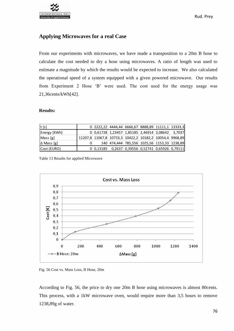
Rud. Prey
76
Applying Microwaves for a real Case
From our experiments with microwaves, we have made a transposition to a 20m B hose to
calculate the cost needed to dry a hose using microwaves. A ratio of length was used to
estimate a magnitude by which the results would be expected to increase. We also calculated
the operational speed of a system equipped with a given powered microwave. Our results
from Experiment 2 Hose „B‟ were used. The cost used for the energy usage was
21,36cents/kWh[42].
Results:
Table 13 Results for applied Microwave
Fig. 56 Cost vs. Mass Loss, B Hose, 20m
According to Fig. 56, the price to dry one 20m B hose using microwaves is almost 80cents.
This process, with a 1kW microwave oven, would require more than 3,5 hours to remove
1238,89g of water.
t [s] 0 2222,22 4444,44 6666,67 8888,89 11111,1 13333,3
Energy [KWh] 0 0,61728 1,23457 1,85185 2,46914 3,08642 3,7037
Mass [g] 11207,8 11067,8 10733,3 10422,2 10182,2 10054,4 9968,89
∆ Mass [g] 0 140 474,444 785,556 1025,56 1153,33 1238,89
Cost (EURO) 0 0,13185 0,2637 0,39556 0,52741 0,65926 0,79111

Rud. Prey
77
Sn: speed at power n (m/s)
Pn: power n (kW)
Operational speed
According to the rule showed in the Appendix A.3, the microwave is a proportional system.
We can use the following calculation for creating a microwave power versus operating speed
graph.
Power microwave: 1kW:
For a 0,18m piece of hose we spend 120s to dry. Thus, for 0,10m (length of the microwave)
we spend:
Now ,the speed can be easily calculated:
Power microwave: 2kW:
The speed that the hose must run through the microwave of 1kW of power is 0,0015m/s.
Now, we calculate this speed for a microwave of 2kW:
Finally, the formula to find the speed at power n in function of the power is the following:

Rud. Prey
78
Table 14 Results, 20m B Hose
Fig. 57 Microwave Power vs. Operating Speed
This graph allows one to determine the maximum operating speed when drying the hose with
varying powered microwaves. For example, if a 20kW microwave was implemented, the
operating speed must be no greater than 0.03m/s to dry a 20m hose. The relationship shown in
Fig. 57 is not dependent on the length (size dimensions) of the machine.
Length of piece 0,1 m * Speed and time to dry hose are not dependent on length
Power[kW] 0,0001 1 2 3 4 5 10 20 30 40 50
time to dry piece [s] 6,67E+05 66,7 33,3 22,2 16,7 13,3 6,7 3,3 2,2 1,7 1,3
Speed [m/s] 0 0,0015 0,0030 0,0045 0,0060 0,0075 0,0150 0,0300 0,0450 0,0600 0,0750
time to dry hose [s] 1,33E+08 13333,3 6666,7 4444,4 3333,3 2666,7 1333,3 666,7 444,4 333,3 266,7
Rud. Prey
79
Conclusion
From our experiments with temperature and mass, we concluded that microwave technology
is a feasible method to dry fire hoses. However, factors that need to be considered when
using microwaves include: the space between the surface of the microwave and the surface of
the hose, the other materials in the microwave that are also being exposed to the radiation, and
the use of forced or free convection. Caution should also be taken not to exceed temperatures
about 150°C, as damage is likely to occur. Once the water has been removed from the hose, it
is necessary to stop exposure time to prevent such high temperatures. Forced convection
during the microwave process did not speed up the drying process as expected, but it does
allow for a more controlled and constant rate of mass loss. The time to dry a fire hose
completely with microwaves is greater than the current existing methods. The power
requirements for microwaves are high and thus costs to operate this equipment would be
higher than current methods. Also, it would not be recommended to use microwaves for an
entire drying process.
Rud. Prey
80
8.2. Conduction
We performed 4 experiments with an iron to simulate a system by conduction, where perhaps
the hose would pass over a system of heated cylinders in a process. Effects due to temperature
were evaluated as well as the effect of forced convection on mass loss. The temperature of the
iron was adjusted using a setting of full power and half power, and the forced convection was
simulated using a hair dryer.
Experiments and Results
Materials
Scale (Satorius Type 1547)
Infrared Camera (FLUKE Ti32)
Iron (Philips Mistral HI 312, 1200-1450W)
Hair dryer (BomannCB 870, 1800W)
Bucket of Water
Several pieces of hose; varying in size:
o Hose 6: 19,2cm in length
o Hose C: 18cm in length
o Hose 4: 17,5cm in length
Experiments
1. Iron with half power of 1325W
2. Iron with full power of 1450W
3. Iron with full power of 1450W, plus hair dryer
4. Iron with half power of 1325W, plus hair dryer
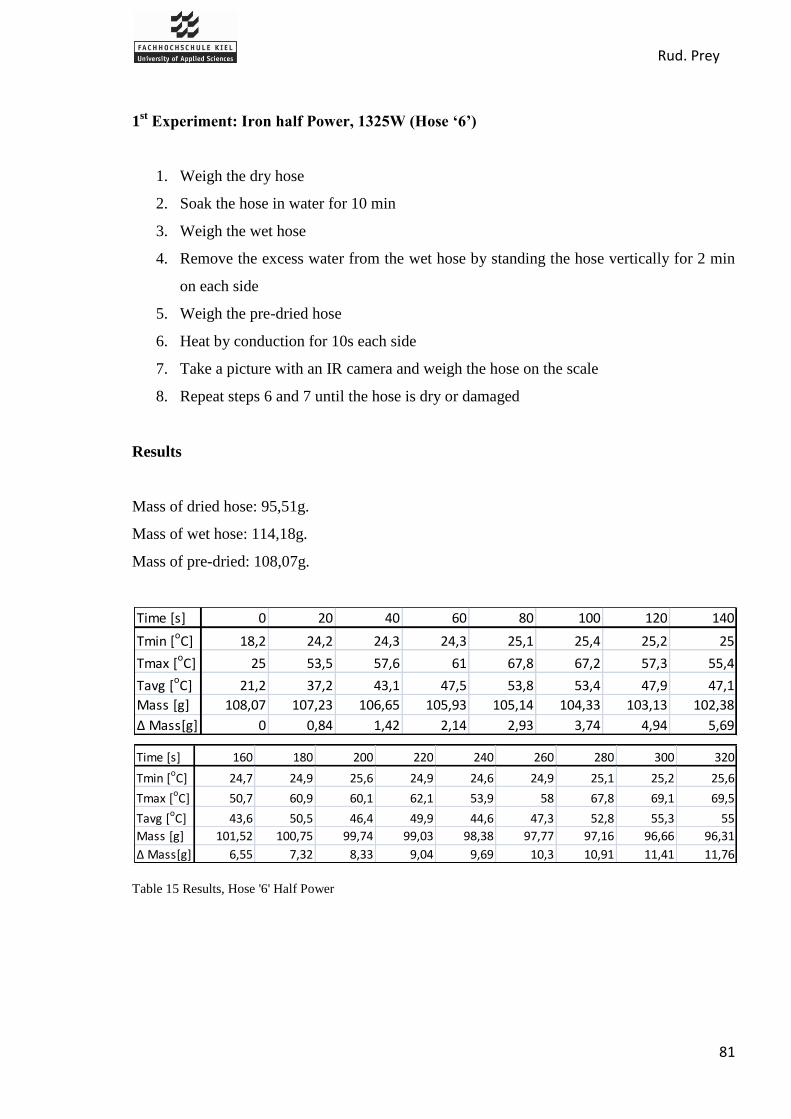
Rud. Prey
81
1st Experiment: Iron half Power, 1325W (Hose ‘6’)
1. Weigh the dry hose
2. Soak the hose in water for 10 min
3. Weigh the wet hose
4. Remove the excess water from the wet hose by standing the hose vertically for 2 min
on each side
5. Weigh the pre-dried hose
6. Heat by conduction for 10s each side
7. Take a picture with an IR camera and weigh the hose on the scale
8. Repeat steps 6 and 7 until the hose is dry or damaged
Results
Mass of dried hose: 95,51g.
Mass of wet hose: 114,18g.
Mass of pre-dried: 108,07g.
Table 15 Results, Hose '6' Half Power
Time [s] 0 20 40 60 80 100 120 140
Tmin [oC] 18,2 24,2 24,3 24,3 25,1 25,4 25,2 25
Tmax [oC] 25 53,5 57,6 61 67,8 67,2 57,3 55,4
Tavg [oC] 21,2 37,2 43,1 47,5 53,8 53,4 47,9 47,1
Mass [g] 108,07 107,23 106,65 105,93 105,14 104,33 103,13 102,38
∆ Mass[g] 0 0,84 1,42 2,14 2,93 3,74 4,94 5,69
Time [s] 160 180 200 220 240 260 280 300 320
Tmin [oC] 24,7 24,9 25,6 24,9 24,6 24,9 25,1 25,2 25,6
Tmax [oC] 50,7 60,9 60,1 62,1 53,9 58 67,8 69,1 69,5
Tavg [oC] 43,6 50,5 46,4 49,9 44,6 47,3 52,8 55,3 55
Mass [g] 101,52 100,75 99,74 99,03 98,38 97,77 97,16 96,66 96,31
∆ Mass[g] 6,55 7,32 8,33 9,04 9,69 10,3 10,91 11,41 11,76
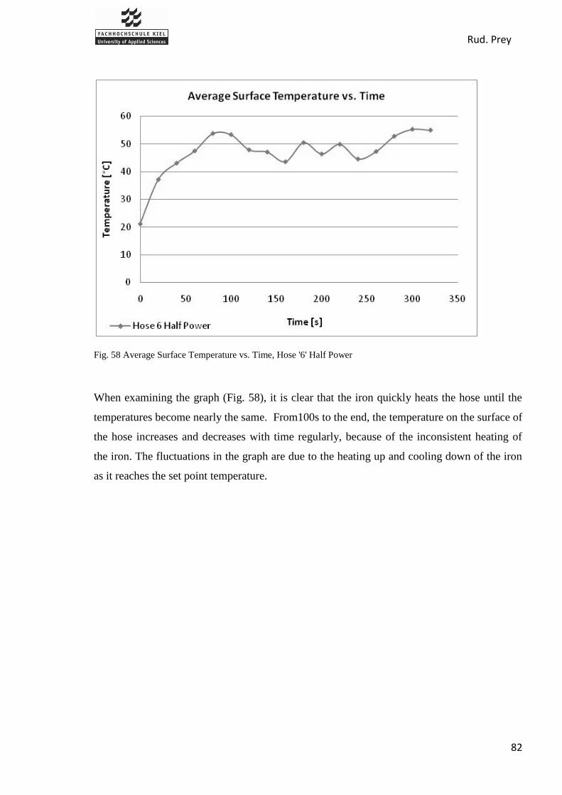
Rud. Prey
82
Fig. 58 Average Surface Temperature vs. Time, Hose '6' Half Power
When examining the graph (Fig. 58), it is clear that the iron quickly heats the hose until the
temperatures become nearly the same. From100s to the end, the temperature on the surface of
the hose increases and decreases with time regularly, because of the inconsistent heating of
the iron. The fluctuations in the graph are due to the heating up and cooling down of the iron
as it reaches the set point temperature.

Rud. Prey
83
Fig. 59 Mass Loss vs. Time, Hose '6' Half Power
The overall mass loss with respect to time was constant and produced linear results, with the
iron at half power (Fig. 59). This does not however, represent the individual mass loss from
each 20 second interval. The fluctuation in temperature would have a more obvious effect in
this area. After doing the experiment the hose was dried after 320 seconds and without
damage.
2nd
Experiment: Iron full Power, 1400W (Hose ‘C’)
1. Weigh the dry hose
2. Soak the hose in water for 10 min
3. Weigh the wet hose
4. Remove the excess water from the wet hose by standing the hose vertically for 2 min
on each side
5. Weigh the pre-dried hose
6. Heat by conduction for 10s each side
7. Take a picture with an IR camera and weigh the hose on the scale
8. Repeat steps 6 and 7 until the hose is dry or damaged
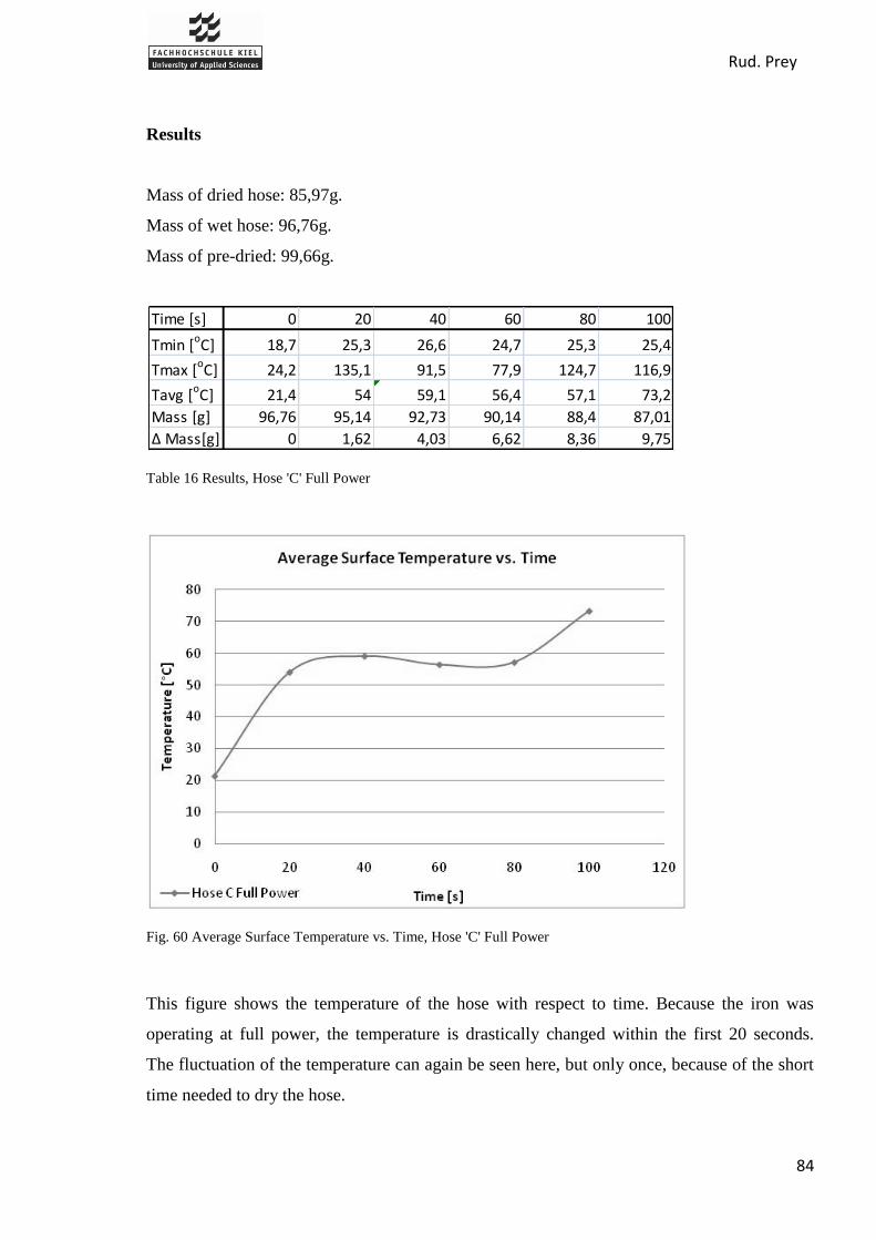
Rud. Prey
84
Results
Mass of dried hose: 85,97g.
Mass of wet hose: 96,76g.
Mass of pre-dried: 99,66g.
Table 16 Results, Hose 'C' Full Power
Fig. 60 Average Surface Temperature vs. Time, Hose 'C' Full Power
This figure shows the temperature of the hose with respect to time. Because the iron was
operating at full power, the temperature is drastically changed within the first 20 seconds.
The fluctuation of the temperature can again be seen here, but only once, because of the short
time needed to dry the hose.
Time [s] 0 20 40 60 80 100
Tmin [oC] 18,7 25,3 26,6 24,7 25,3 25,4
Tmax [oC] 24,2 135,1 91,5 77,9 124,7 116,9
Tavg [oC] 21,4 54 59,1 56,4 57,1 73,2
Mass [g] 96,76 95,14 92,73 90,14 88,4 87,01
∆ Mass[g] 0 1,62 4,03 6,62 8,36 9,75

Rud. Prey
85
Fig. 61 Mass Loss vs. Time, Hose 'C' Full Power
It only took 100s to dry the hose piece using full power, but as a result of the intensive
amount of heat, the hose became damaged. The fibers on outer jacket of the hose begin to
shrink if excess heat is applied once the water is removed.
3rd
Experiment: Iron full Power + Hair Dryer (Hose ‘6’)
1. Weigh the dry hose
2. Soak the hose in water for 10 min
3. Weigh the wet hose
4. Remove the excess water from the wet hose by standing the hose vertically for 2 min
on each side
5. Weigh the pre-dried hose
6. Heat by conduction for 10s each side
7. Dry by convection 10s with hair dryer (distance 15cm)
8. Take a picture with an IR camera and weigh the hose on the scale
9. Repeat steps 6 through 7 until the hose is dry or damaged

Rud. Prey
86
Results
Mass of dried hose: 95,51g.
Mass of wet hose: 111,98g.
Mass of pre-dried: 107,04g.
Table 17 Results, Hose '6' Full Power with Hair Dryer
Fig. 62 Average Surface Temperature vs. Time, Hose '6' Full Power with Hair Dryer
Compared to the 2nd
experiment without the hair dryer, this shows how the influence of forced
convection results in lower surface temperatures. It is consistently 10°C lower than without.
The curve of temperature for this experiment has a slower initial increase than the experiment
without the hair dryer, but the pattern of temperature change is almost identical.
Time [s] 0 20 40 60 80 100
Tmin [oC] 18,5 25,6 26,1 25,7 26,6 25,2
Tmax [oC] 24,4 48,1 52,7 106,5 57,2 83,8
Tavg [oC] 21,7 37,3 45 46,6 42,9 55,8
Mass [g] 107,04 104,98 102,14 100,03 97,77 95,58
∆ Mass[g] 0 2,06 4,9 7,01 9,27 11,46

Rud. Prey
87
Fig. 63 Mass Loss vs. Time, Hose '6' Full Power with Hair Dryer
After doing the experiment, the hose was dried and without damage. In the same amount of
time, the experiment with the hair dryer managed to remove nearly 1 more gram of water than
the experiment without.
4th
Experiment: Iron half Power + Hair Dryer (Hose ‘4’)
1. Weigh the dry hose
2. Soak the hose in water for 10 min
3. Weigh the wet hose
4. Remove the excess water from the wet hose by standing the hose vertically for 2 min.
on each side
5. Weigh the pre-dried hose
6. Heat by conduction for 10s each side
7. Dry by convection 10s with hair dryer (distance 15cm)
8. Take a picture with an IR camera and weigh the hose on the scale
9. Repeat steps 6 through 7 until the hose is dry or damaged

Rud. Prey
88
Results
Mass of dried hose: 86,33g.
Mass of wet hose: 102,51g.
Mass of pre-dried: 97,80g.
Table 18 Results, Hose '4' Half Power with Hair Dryer
Fig. 64 Average Temperature vs. Time, Hose '4' Half Power with Hair Dryer
Time [s] 0 20 40 60 80 100 120
Tmin [oC] 18,5 24,2 25,8 25,7 23,8 23,6 25,8
Tmax [oC] 25 38,8 42,1 38 37,2 39,1 41,1
Tavg [oC] 21,7 29,8 31,7 31,5 32,8 33,8 34,9
Mass [g] 97,8 96,75 95,71 94,71 93,91 93,18 92,25
∆ Mass[g] 0 1,05 2,09 3,09 3,89 4,62 5,55
Time [s] 140 160 180 200 220 240 260
Tmin [oC] 25,6 25,7 25,6 24,2 25,7 25,7 25,6
Tmax [oC] 41,3 43,9 41,9 45,3 46 49,4 47,1
Tavg [oC] 35 37,7 35,8 37,2 38,2 39,1 38,2
Mass [g] 91,33 90,54 89,91 89,02 88,3 87,71 87,28
∆ Mass[g] 6,47 7,26 7,89 8,78 9,5 10,09 10,52
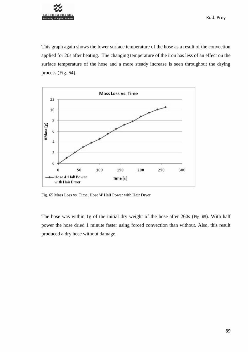
Rud. Prey
89
This graph again shows the lower surface temperature of the hose as a result of the convection
applied for 20s after heating. The changing temperature of the iron has less of an effect on the
surface temperature of the hose and a more steady increase is seen throughout the drying
process (Fig. 64).
Fig. 65 Mass Loss vs. Time, Hose '4' Half Power with Hair Dryer
The hose was within 1g of the initial dry weight of the hose after 260s (Fig. 65). With half
power the hose dried 1 minute faster using forced convection than without. Also, this result
produced a dry hose without damage.
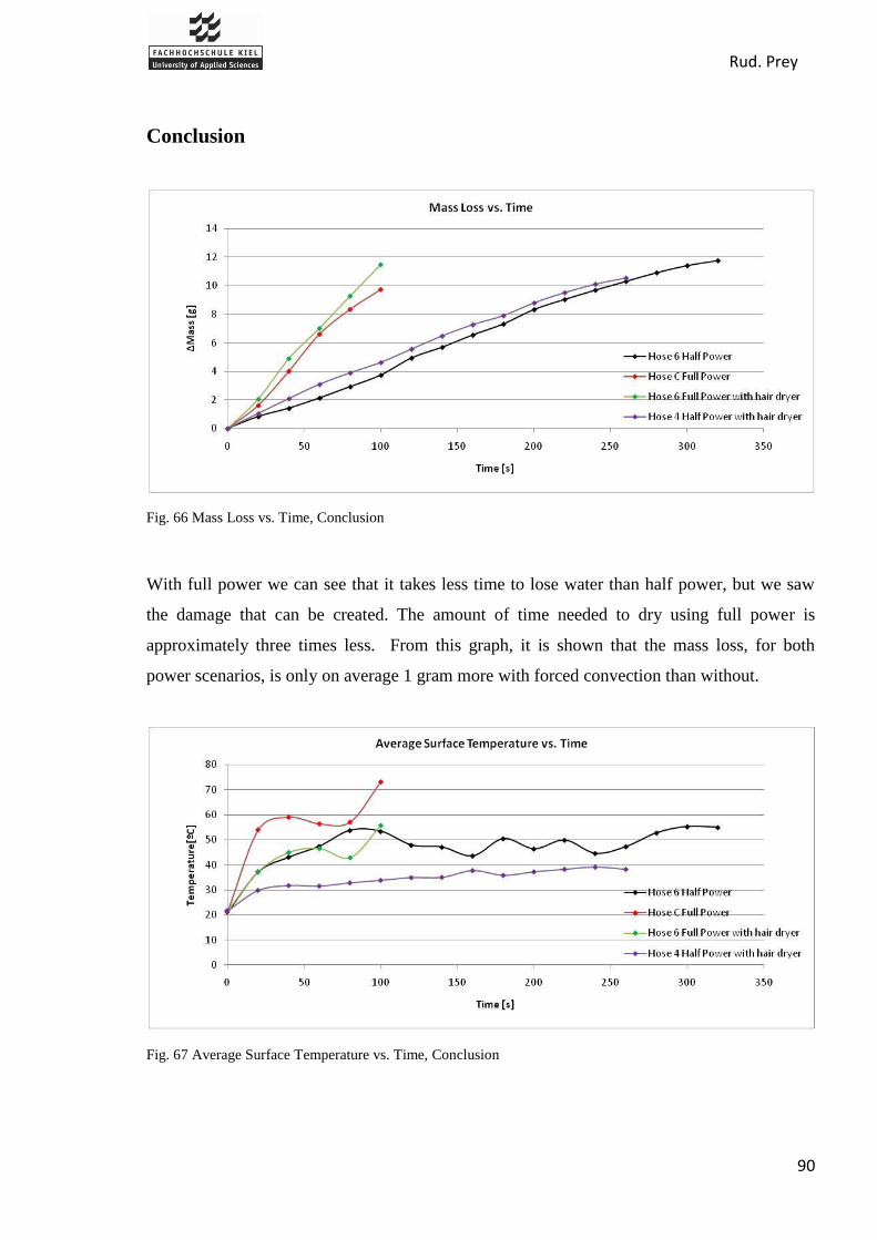
Rud. Prey
90
Conclusion
Fig. 66 Mass Loss vs. Time, Conclusion
With full power we can see that it takes less time to lose water than half power, but we saw
the damage that can be created. The amount of time needed to dry using full power is
approximately three times less. From this graph, it is shown that the mass loss, for both
power scenarios, is only on average 1 gram more with forced convection than without.
Fig. 67 Average Surface Temperature vs. Time, Conclusion

Rud. Prey
91
With the temperature, it is easier to see the importance of moving the evaporated water from
the hose using forced convection. This simple process allows a low enough temperature for
the hose to be dried using the full powered iron.
With the results from the conduction experiments, it was concluded that we were unable to
accurately simulate a process that could be used to dry fire hoses. The inconsistency in the
experiments from the equipment gives reason to find these results invalid. Because of the
fluctuating temperature, it was impossible to determine the power being used by the iron at all
times. Thus, we are unable to calculate the energy consumption and costs of such method.
Our results do, however, provide a comparison of different approaches to drying by
conduction. he benefit of forced convection can be seen, as well as the advantage and
disadvantage of using more heat to dry. If the results were accurate, it would be recommended
to dry fire hoses using highly heated cylinders to increase time, with forced convection to
move the steam from the area and prevent the hose from becoming damaged.
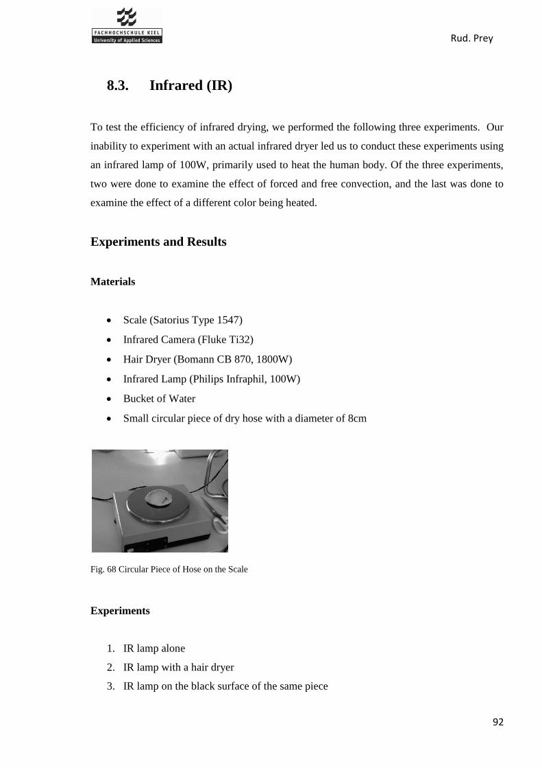
Rud. Prey
92
8.3. Infrared (IR)
To test the efficiency of infrared drying, we performed the following three experiments. Our
inability to experiment with an actual infrared dryer led us to conduct these experiments using
an infrared lamp of 100W, primarily used to heat the human body. Of the three experiments,
two were done to examine the effect of forced and free convection, and the last was done to
examine the effect of a different color being heated.
Experiments and Results
Materials
Scale (Satorius Type 1547)
Infrared Camera (Fluke Ti32)
Hair Dryer (Bomann CB 870, 1800W)
Infrared Lamp (Philips Infraphil, 100W)
Bucket of Water
Small circular piece of dry hose with a diameter of 8cm
Fig. 68 Circular Piece of Hose on the Scale
Experiments
1. IR lamp alone
2. IR lamp with a hair dryer
3. IR lamp on the black surface of the same piece

Rud. Prey
93
1st Experiment: IR Lamp alone (Circle)
1. Weigh the dry hose
2. Soak the hose in water for 10 min
3. Weigh the wet hose
4. Remove the excess water from the wet hose by standing the hose vertically for 1 min
on each side
5. Weigh the pre-dried hose
6. Heat by infrared radiation in 1 min intervals
7. Take a picture with an IR camera and weigh the hose on the scale
8. Repeat steps 6 and 7 until the hose is dry or damaged
Results:
Mass of dried hose: 9,59g.
Mass of wet hose: 11,48g.
Mass of pre-dried: 10,92g.
Table 19 Results, Circular Piece, IR
Time [min] 0 1 2 3 4 5 6 7 8
Energy [KWh] 0,0000 0,0017 0,0033 0,0050 0,0067 0,0083 0,0100 0,0117 0,0133
Tmin [oC] 18,3 26,6 35,4 30,1 27,1 31,6 26,4 31,2 30,5
Tmax [oC] 25 49,8 55,8 55,7 61,5 56,5 61,1 74,2 86,3
Tavg [oC] 22 42,2 48,6 47,9 47,4 48,4 48,7 56 65,2
Mass [g] 10,92 10,74 10,53 10,3 10,11 9,93 9,75 9,67 9,61
∆ Mass[g] 0 0,18 0,39 0,62 0,81 0,99 1,17 1,25 1,31
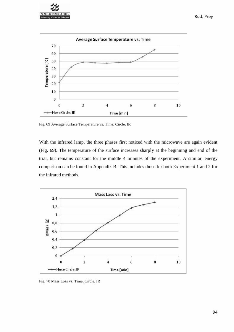
Rud. Prey
94
Fig. 69 Average Surface Temperature vs. Time, Circle, IR
With the infrared lamp, the three phases first noticed with the microwave are again evident
(Fig. 69). The temperature of the surface increases sharply at the beginning and end of the
trial, but remains constant for the middle 4 minutes of the experiment. A similar, energy
comparison can be found in Appendix B. This includes those for both Experiment 1 and 2 for
the infrared methods.
Fig. 70 Mass Loss vs. Time, Circle, IR

Rud. Prey
95
The mass loss for the infrared drying steadily increases until there is 0,2g of water left in the
material. At this point (around 6 minutes) the increased exposure becomes a waste of energy
as little water is left to be removed.
2nd
Experiment: IR Lamp + Hair Dryer (Circle)
1. Weigh the dry hose
2. Soak the hose in water for 10 min
3. Weigh the wet hose
4. Remove the excess water from the wet hose by standing the hose vertically for 1 min
on each side
5. Weigh the pre-dried hose
6. Heat with the IR lamp for 1min while the hair dryer blows air from 30 cm away
7. Take a picture with an IR camera and weigh the hose on the scale
8. Repeat steps 6 and 7 until the hose is dry or damaged
Results
Mass of dried hose: 9,59g.
Mass of wet hose: 11,52g.
Mass of pre-dried: 11,03g.
Table 20 Results, Circle, IR with Hair Dryer
Time [min] 0 1 2 3 4 5 6
Energy [KWh] 0,0000 0,0017 0,0033 0,0050 0,0067 0,0083 0,0100
Tmin [oC] 18,1 25 25 28,9 28,3 32,4 27,5
Tmax [oC] 24,8 37,3 38,9 37,9 43,1 51 56,2
Tavg [oC] 21,9 32,8 34,2 33,3 35,3 39,9 44,3
Mass [g] 11,03 10,71 10,39 10,09 9,88 9,71 9,65
∆ Mass[g] 0 0,32 0,64 0,94 1,15 1,32 1,38

Rud. Prey
96
Fig. 71 Average Surface Temperature vs. Time, Circle, IR with Hair Dryer
This graph, although similar to the first with the three phases, has a slower rate of changing
temperature at the beginning and end. By the end of the experiment, the average surface
temperature does not exceed 45°C.
Fig. 72 Mass Loss vs. Time, Circle, IR with Hair Dryer
With the addition of the hair dryer, the hose circle dried in 6 minutes. As the mass of water in
the hose decreases, more time and energy is needed to remove the remainder.

Rud. Prey
97
3rd
Experiment: IR Lamp on black Surface (Circle)
This experiment was done without weighing the hose after each 1 minute interval. The goal
was to examine the effect of color on temperature. The following procedure was performed:
1. Weigh the dry hose
2. Soak the hose in water for 10 mn
3. Weigh the wet hose
4. Remove the excess water from the wet hose by
standing the hose vertically for 1 min on each side
5. Weigh the pre-dried hose
6. Heat with the IR lamp for 1min
7. Take a picture with IR camera after 1 min of heating
8. Repeat until damage or maximum temperature is reached
Fig. 73 Black Side of the Hose, IR
Results:
Mass dried hose: 9,59g.
Mass wet hose: 11,42g.
Mass pre-dried: 10,97g.
Table 21 Results, Circle, IR
Time [min] 0 1 2 3 4
Energy [KWh] 0,0000 0,0017 0,0033 0,0050 0,0067
Tmin [oC] 18,6 24 25,6 25 26,1
Tmax [oC] 25 82,2 114,6 114,8 109,8
Tavg [oC] 21,4 57,2 74,7 73,4 74,1

Rud. Prey
98
Fig. 74 Average Surface Temperature vs. Time, Circle
We can see the effect of the color on the surface being heated (Fig. 74). Black absorbs light
instead of white, which reflect light. As a result the black surface becomes hotter than the
other. We can see the different between both surfaces. The black surface is nearly 25°C
warmer than IR drying without hair dryer, within the first two minutes. This comparison also
shows the difference between the drying with and without forced convection. The hose was
only damaged in the last experiment with the black surface. (Fig. 75).
Fig. 75 Damaged Circle due to long-term Exposure of IR

Rud. Prey
99
Applying Infrared for a real Case
In order to estimate the cost and energy usage of implementing an infrared drying method to
dry fire hoses, we have used our experimental data from the first infrared experiment. We
have made a transposition to a 20m B hose to calculate the cost needed to dry an entire hose
using infrared drying. We already know that the cost of a 1KWh is 21,36cents.
Results:
Table 22 Results, 20m B Hose
Fig. 76 Cost vs. Mass Loss, 20m B Hose
From this graph, a linear relationship can be found for the first 1100 grams of water, but the
energy required to remove the last 100 grams causes the price to increase faster toward the
end (Fig. 76). It would cost approximately 2, € to dry one 20m B hose completely with
infrared drying using a similar technique to that of the experiment. This result has to take
cautiously because our lamp was not optimized to heat a hose but to heat the body, we know
Time [min] 0 937,4223 1874,845 2812,267 3749,689 4687,111 5624,534 6561,956 7499,378
Energy [KWh] 0 1,56237 3,124741 4,687111 6,249482 7,811852 9,374223 10,93659 12,49896
Mass [g] 10236,65 10067,92 9871,057 9655,45 9477,339 9308,603 9139,867 9064,874 9008,628
∆ Mass[g] 0 168,736 365,5947 581,2018 759,3121 928,0481 1096,784 1171,778 1228,023
Cost [EURO] 0 0,333722 0,667445 1,001167 1,334889 1,668612 2,002334 2,336056 2,669779

Rud. Prey
100
which importance has it in the case of infrared radiation (see the description of infrared
radiation)
Operational speed
For this part we used in the case of microwave a proportional rule (Appendix A.3). This rule
does not work for infrared because of its principle.
Conclusion
From the results, we can conclude that infrared heating effectively dries the hoses without
damage. However, this method is rather time consuming. With the addition of forced
convection, we are able to reduce the temperature of the hose while drying and speed up the
drying process. We would expect different results with different colored hoses, and damage
may result if the temperature of the inside rubber exceeds 70ºC. It is important to note that our
results are representative of an infrared lamp (for heating), not an infrared dryer (for drying).
The principle is the same, but the energy and efficiency are not.

Rud. Prey
101
9. Suggestions
From our results, our first conclusion is that microwave and infrared drying are expensive
methods when compared to current methods. Because of this, and the possible damage caused
by long exposure with these methods, we would not recommend a process that solely dries a
fire hose with one of these methods. Thus, our suggestion is to incorporate such a method into
an existing process, using it just after a mechanical method has pre-dried the hose. This would
be represented by the first phase of the drying process, where the powerful method is used to
quickly raise the temperature of the water molecules. For example, according to the graph
below (Fig. 77), we would use the infrared for approximately the first 1 minute and 30
seconds.
Fig. 77 Average Surface Temperature vs. Time, IR
Phase 1 The material is heated and the water starts to evaporate.
Phase 2 The water continues to evaporate because of the heat produced in phase one.
The temperature remains or increases slowly during the entirety of the phase.
Phase 3 All water has evaporated and the temperature on the surface increases
extremely.
The objective of this step would be to heat the water quickly in a short period of time, and
then remove the remaining liquid and vapour using a system that requires less energy and
does not cause damage to the hose.
1 2 3

Rud. Prey
102
We would suggest the following three step process. A mix of one method from each of the 3
steps would be recommended. Below are listed the possible methods with which we have
experimental data:
Vacuum
Centrifugation
Wipe
Air knives
Squeeze rolls
Infrared
Iron
Microwaves
Forced
Natural
Fig. 78 Cost vs. Mass Loss, MW, IR
According to the experimental results we determined the best technology for the “Powerful
method” to be microwave heating because it provided a faster drying time and was cheaper
than infrared. The microwave heated the water faster and with less energy.
First we must decide which technology should be suggested for pre-drying. Rud. Prey has
already performed experiments testing the majority of the mechanical methods (Appendix D),
00,25
0,50,75
11,25
1,51,75
22,25
2,52,75
3
0 200 400 600 800 1000 1200 1400
Co
st [
€]
∆Mass [g]
Cost vs. Mass Loss
Microwave
IR
Pre-drying:
Mechanical methods
Heating of water: Powerful
methods
Evaporation:
Air convection

Rud. Prey
103
and from their results, it is clear that suction is the most effective method of pre-drying a fire
hose.
For the last step, we would suggest forced convection because it requires less time than
natural convection and ultimately achieves the same level of dryness. Although forced
convection requires additional use of energy, the time saved is more important when
considering a process system.
Thus, our suggestion is the following:
For pre-drying, we suggest to use suction. For the next step, use microwaves to achieve the
evaporation temperature faster than with existing technologies. After this, we recommend
using forced convection because it is cheaper than using microwaves for the whole
evaporation process.

Rud. Prey
104
10. Experiment of Our Suggestion
In order to test the suggestion made from the initial experiments, a final experiment was
performed using the three suggested processes. Our objective was to see if the efficiency
would be greater than using only microwave radiation. Several experiments were made, and
we hoped to find the most effect time interval for microwave drying. This would theoretically
provide a small scale example of a hypothetical machine. For this experiment we wanted to
determinate:
Time to dry a piece of hose
Power that we need to dry
Mass Loss vs. Time to see the efficiency of the method
10.1. Experiment and Results
Materials
Vacuum cleaner with 0,93K watts of power (Ribo-GmbH T90)
Microwave oven with 900 watts of power (Siemens HF24022)
Hair dryer with 1800Wwatts of power (Boman CB870)
Scale (Satorius Type 1547)
2 pieces of dry „B‟ hose with a length of 20 centimeter (Hose „11‟ and Hose „12‟)
Bucket of water
Procedure of the Experiments
The goal for the four experiments was to measure the mass (Mass[g]) versus the time (t[s])
and calculate the difference in mass as the hose dried. Our procedure was the same in each
experiment, and it is as follows:
1. Weigh the dry hose
2. Soak the hose in water for 10 minutes

Rud. Prey
105
3. Weigh the wet hose
4. Remove the excess water on the wet hose by suction, using the vacuum cleaner
specified above for 5 seconds on each side of the hose
5. Weigh the pre-dried hose
6. Put the hose in the microwave oven
7. Take the hose out of the oven after the time described in the explanation of each
experiment
8. Weigh the hose
9. Blow the fire hose with a hair dryer at full power for 10 seconds on each side
10. Weigh the hose after each 20 second interval until it becomes dry or damaged.
1st Experiment: Fire hose ‘11’
Three Phase Procedure:
1st Step: After weighing the dry hose, 5 seconds of suction was performed on each side
of the hose and it was weighed.
2nd
Step: The hose was placed for 40 seconds inside the microwave oven and weighed
afterward.
3rd
Step: Forced air convection was applied for 10 seconds on each side of the hose
and weighed every 20 seconds until the hose was dry.
Results:
Weight of dry hose: 101,51g.
Weight of wet hose: 120,24g.
Weight of the hose after Suction: 115,82g.
Weight of the hose after Microwave: 113,54g.
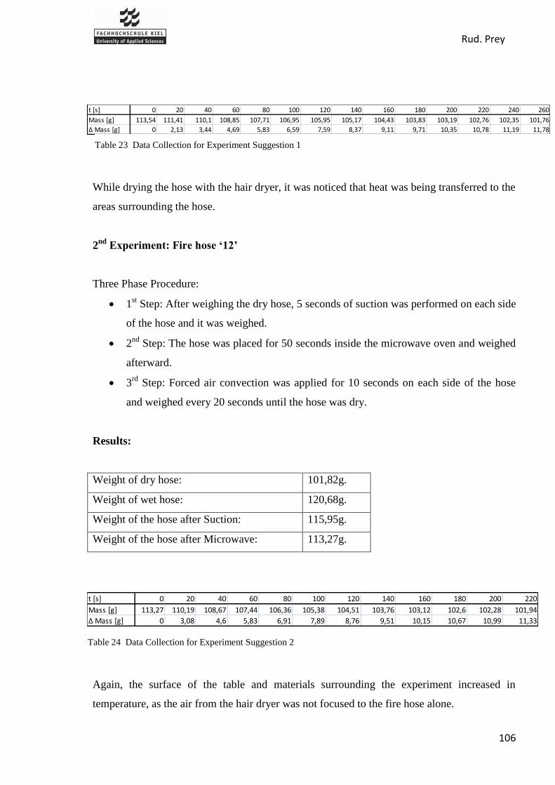
Rud. Prey
106
While drying the hose with the hair dryer, it was noticed that heat was being transferred to the
areas surrounding the hose.
2nd
Experiment: Fire hose ‘12’
Three Phase Procedure:
1st Step: After weighing the dry hose, 5 seconds of suction was performed on each side
of the hose and it was weighed.
2nd
Step: The hose was placed for 50 seconds inside the microwave oven and weighed
afterward.
3rd
Step: Forced air convection was applied for 10 seconds on each side of the hose
and weighed every 20 seconds until the hose was dry.
Results:
Weight of dry hose: 101,82g.
Weight of wet hose: 120,68g.
Weight of the hose after Suction: 115,95g.
Weight of the hose after Microwave: 113,27g.
Again, the surface of the table and materials surrounding the experiment increased in
temperature, as the air from the hair dryer was not focused to the fire hose alone.
t [s] 0 20 40 60 80 100 120 140 160 180 200 220 240 260
Mass [g] 113,54 111,41 110,1 108,85 107,71 106,95 105,95 105,17 104,43 103,83 103,19 102,76 102,35 101,76
∆ Mass [g] 0 2,13 3,44 4,69 5,83 6,59 7,59 8,37 9,11 9,71 10,35 10,78 11,19 11,78
t [s] 0 20 40 60 80 100 120 140 160 180 200 220
Mass [g] 113,27 110,19 108,67 107,44 106,36 105,38 104,51 103,76 103,12 102,6 102,28 101,94
∆ Mass [g] 0 3,08 4,6 5,83 6,91 7,89 8,76 9,51 10,15 10,67 10,99 11,33
Table 23 Data Collection for Experiment Suggestion 1
Table 24 Data Collection for Experiment Suggestion 2

Rud. Prey
107
3th
Experiment: Fire hose ‘12’
Three Phase Procedure:
1st Step: After weighing the dry hose, 5 seconds of suction was performed on each side
of the hose and it was weighed.
2nd
Step: The hose was placed for 50 seconds inside the microwave oven and weighed
afterward.
3rd
Step: Forced air convection was applied inside the hose with the hair dryer in 20
second intervals and weighed after each until the hose was dry.
Results:
Weight of dry hose: 101,82g.
Weight of wet hose: 121,58g.
Weight of the hose after Suction: 116,60g.
Weight of the hose after Microwave: 113,48g.
This experiment was stopped after 200 seconds because the data showed that we would need
too much time to completely dry the outside of the hose using forced air convection on the
inside. Thus, we stopped the experiment and we concluded that the blowing of hot air is more
efficient on the superficial area of the hose.
t [s] 0 20 40 60 80 100 120 140 160 180 200
Mass [g] 113,48 112,11 111,36 110,9 110,49 110,15 109,75 109,35 109,02 108,63 108,27
∆ Mass [g] 0 1,37 2,12 2,58 2,99 3,33 3,73 4,13 4,46 4,85 5,21
Table 25 Data Collection for Experiment Suggestion 3

Rud. Prey
108
10.2. Graphs and Conclusions:
Fig. 79 Result of Mass Loss for Experiment Suggestion
In this graph we can see the comparison between the three experiments carried out in relation
to the mass loss versus the time to dry. The curves show at time equal to zero that start of the
forced convection process via hair dryer. In general, the convection method used on the
outside of the hose was more effective than on the inside. When the 40 and 50 s experiments
are compared, it shows that 40 s of drying with the microwave is slower and 50 seconds
provides better results. By increasing the time of microwave exposure by 10 s, we were able
to increase the overall drying time by more than 30 s. This can be explained by the greater
efficiency of microwaves over forced convection in our experiment. In our suggestion we
proposed the use of microwaves in the first phase of the drying process (approximately 40 s)
because of the high level of energy consumption during the complete process.
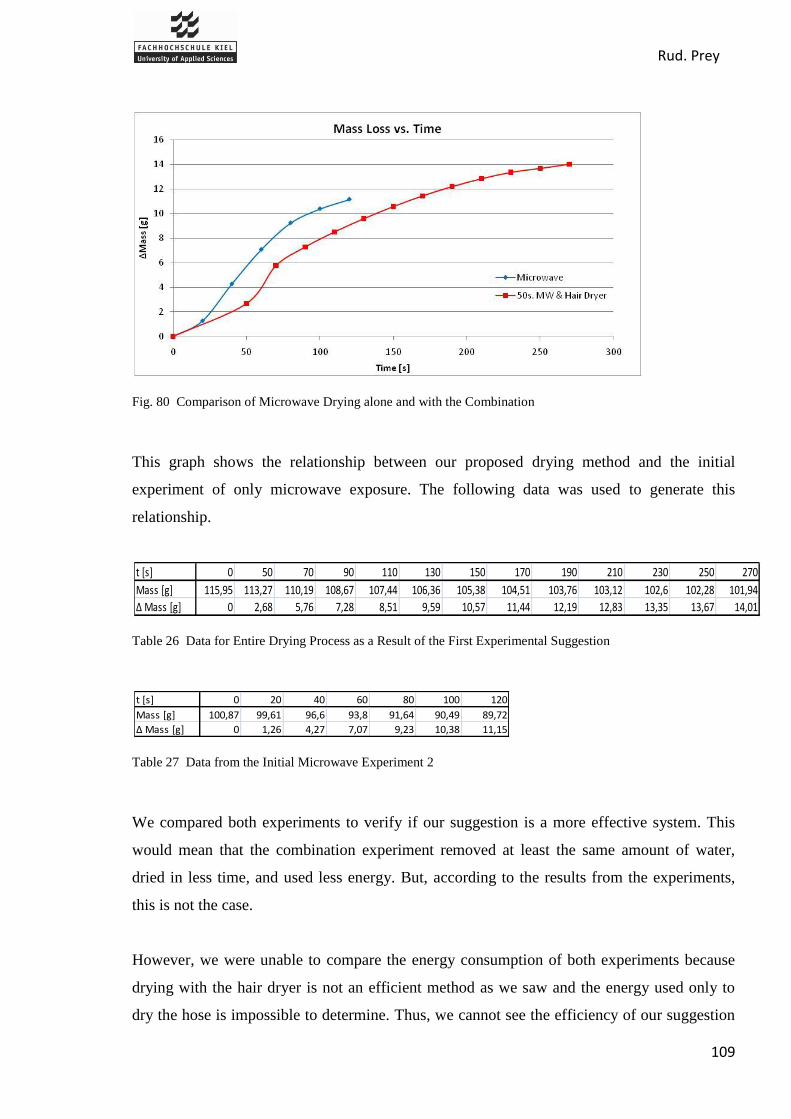
Rud. Prey
109
Fig. 80 Comparison of Microwave Drying alone and with the Combination
This graph shows the relationship between our proposed drying method and the initial
experiment of only microwave exposure. The following data was used to generate this
relationship.
Table 26 Data for Entire Drying Process as a Result of the First Experimental Suggestion
Table 27 Data from the Initial Microwave Experiment 2
We compared both experiments to verify if our suggestion is a more effective system. This
would mean that the combination experiment removed at least the same amount of water,
dried in less time, and used less energy. But, according to the results from the experiments,
this is not the case.
However, we were unable to compare the energy consumption of both experiments because
drying with the hair dryer is not an efficient method as we saw and the energy used only to
dry the hose is impossible to determine. Thus, we cannot see the efficiency of our suggestion
t [s] 0 50 70 90 110 130 150 170 190 210 230 250 270
Mass [g] 115,95 113,27 110,19 108,67 107,44 106,36 105,38 104,51 103,76 103,12 102,6 102,28 101,94
∆ Mass [g] 0 2,68 5,76 7,28 8,51 9,59 10,57 11,44 12,19 12,83 13,35 13,67 14,01
t [s] 0 20 40 60 80 100 120
Mass [g] 100,87 99,61 96,6 93,8 91,64 90,49 89,72
∆ Mass [g] 0 1,26 4,27 7,07 9,23 10,38 11,15

Rud. Prey
110
because we cannot compare it with the microwave experiment. We were unable to make the
transposition of a 20 meter B hose with our suggestion.
Despite of this, we continue suggesting our improvement because the hose was not damaged
and dried completely. Unlike the microwave experiment, when the hoses finished the drying
process, they were damaged. Also, energy is only one aspect to be consider when developing
a drying method and although we are unable to know exactly the power usage, time to dry,
and water mass loss of an entire hose, the principle of remains the same and our suggested
method would be effective.
Rud. Prey
111
11. Conclusion
The start of this report describes fire hoses, which are the foremost used equipment to fight
fires. They are washed and tested regularly, and therefore need to be dried. Hoses are
composed of synthetic material or cotton on the outside and rubber on the inside. The
absorption of water into the material during the washing process must be removed before
storage, to prevent damage from mould.
In addition, all hose drying technologies in the market from Rud. Prey and their competitors
are presented. The best way to dry a hose is a hanging system, which needs a tower.
Although, simple, efficient (natural air convection), and cheap with high capacity, these
systems require nevertheless a tower. The tower‟s height can be up to twenty-five meters,
which is not allowed or possible in some fire department. For this reason companies have
developed alternative systems, which include drying cabinets or automatic drying systems
integrated into the hose care process. All machines incorporate a technique of forced air
convection to dry completely.
Our project was created to design, suggest, or improve an existing hose drying system, using
research from other industrial sectors. Six methods, found primarily in textile, food-
processing, and paper industries, are able to dry: three radiation methods (infrared, microwave
and radiofrequency), a conduction method (using heat rolls), a chemical method (with
inorganic salts) and a mechanical method (centrifuge).
Experiments show limits to these technologies, as they are expensive to dry completely and
present the possibility of damaging the hose. According to a usual drying process (Fig. 77),
the best way to dry is through a combination of methods, and thus one step is added to the
usual drying system: after pre-drying by suction, the water is heated up by microwave
radiation. The hose is finally dried by forced air convection. This method is theoretically
efficient but the last experiment does not confirm this assumption, because of the waste of
energy noticed during the experiment.
In conclusion, this project remains open ended, as the process of improvement and design will
never end. Our results show a positive step toward the possibility of a unique technology

Rud. Prey
112
being used to dry fire hoses. With our suggestions, the next step for the company would be to
think about adding this method into a current drying process for a 20 meter B hose. Also,
experimentation of drying with radio frequency and chemical drying agents, which was not
experimented with, should be performed. The first step is completed; Rud.Prey has the
information of beneficial methods, the tools to continue the development of this project, and
the resources to carry out the design.
Rud. Prey
113
12. List of Figures
Fig. 1 Map of Prey's Working Area [1] ...................................................................................... 4
Fig. 2 Map of Prey's Competitors [2] ......................................................................................... 6
Fig. 3 Attack Hose [11] ............................................................................................................. 10
Fig. 4 Supply and Relay Hose [11] ........................................................................................... 10
Fig. 5 Booster Hose [11] ........................................................................................................... 10
Fig. 6 Examples for Suction Hoses [11] ................................................................................... 11
Fig. 7 Mechanical Damage of a Fire Hose [11] ........................................................................ 12
Fig. 8 Exposure of Fire Hoses to the Sun [11].......................................................................... 13
Fig. 9 Organic Damage [11] ..................................................................................................... 13
Fig. 10 Prey, Automatic Hanging System, ASA [1] ................................................................. 16
Fig. 11 Different Adapters for Fire Hoses [1] .......................................................................... 16
Fig. 12 Prey, Circulating Cabinet, SDT [1] .............................................................................. 17
Fig. 13 Prey, Horizontal Rotating System, RSPZ [1] ............................................................... 17
Fig. 14 Prey, Horizontal Process Dryer, SPS-H [1] .................................................................. 18
Fig. 15 Barth, Automatic Hanging System, Bart Lifurmatic III [4] ......................................... 20
Fig. 16 Bockermann, Automatic hanging System, LKA-V [5] ................................................ 20
Fig. 17 Bockermann, Different Adapters for Hose hanging System SBA ............................... 21
Fig. 18 Hafenrichter, Hanging system SAH without adapters [14] .......................................... 22
Fig. 19 Ziegler, Hose Hanging System VSV-C Fig. 20 Ziegler, Hose Hanging System
VSV-LB .................................................................. 22
Fig. 21 Ziegler, Adapter for VSV-C Fig. 22 Ziegler, Adapter for VSV-LB ......................... 23
Fig. 23 Ziegler, Semi Automatic Ring for 20 Hoses, HDK 20 [3] ........................................... 23
Fig. 24 Barth, Drying Cabinet [4] ............................................................................................. 24
Fig. 25 Barth, Hose Carrying Basket ........................................................................................ 25
Fig. 26 Bockermann, Drying Cabinet, STS 821 [5] ................................................................. 25
Fig. 27 Ziegler, Drying Cabinet, STS 10-W [3] ....................................................................... 26
Fig. 28 Circul-Air-Corp., Drying Cabinet [8] ........................................................................... 27
Fig. 29 Bockermann, Slewing Ring, STK 510/20 [5] .............................................................. 27
Fig. 30 Ziegler, Manual Live Ring, MDK 20 [3] ..................................................................... 28
Fig. 31 Ziegler, Inclined Drying System for 20 Hoses ............................................................. 28
Fig. 32 Ziegler, Modular Hose Care Unit, MSP [3] ................................................................. 29

Rud. Prey
114
Fig. 33 Bockermann, Hose Drying Fan [5] .............................................................................. 30
Fig. 34 Bockermann, Four Hose Drying Fan, TG 812 [5] ........................................................ 31
Fig. 35 Hafenrichter, Semi Automatic System, HST [6] .......................................................... 31
Fig. 36 Phase Diagram of Water [12] ....................................................................................... 40
Fig. 37 Principle of Squeezing Rolls ........................................................................................ 42
Fig. 38 Principle of a Shelf Dryer [22] ..................................................................................... 47
Fig. 39 Principle of heating Cylinders with Steam [22] ........................................................... 49
Fig. 40 Principle of Drying by Induction heated Cylinders [23] .............................................. 50
Fig. 41 Electromagnetic Spectrum [24] .................................................................................... 53
Fig. 42 UV-Lamp “Starfire” from Phoseon (Oregon, USA) [2 ] ............................................ 54
Fig. 43 Principle of a Gas Transmitter [30] .............................................................................. 56
Fig. 45 Operation of a MW Oven [32] ..................................................................................... 58
Fig. 44 Components of a MW Oven [32] ................................................................................. 58
Fig. 46 Description of a Radio Frequency Drying System with a Product between the
Electrodes .................................................................................................................................. 60
Fig. 47 Components of a Flash Dryer [41] ............................................................................... 65
Fig. 48 Remove of Excess of Water ......................................................................................... 68
Fig. 49 Take IR Picture of the Inside ........................................................................................ 69
Fig. 50 Take IR Picture of the Outside ..................................................................................... 69
Fig. 51 Average Surface Temperature vs. Time, Outside, Inside ............................................. 70
Fig. 52 Damaged Hose due to long-term Exposure of Microwaves ......................................... 71
Fig. 53 Average Surface Temperature vs. Time, Outside and Inside ....................................... 72
Fig. 54 Hose 'B' vertical in MW Oven ...................................................................................... 73
Fig. 55 Mass Loss vs. Time, Hose 'B' ....................................................................................... 74
Fig. 56 Cost vs. Mass Loss, B Hose, 20m ................................................................................ 76
Fig. 57 Microwave Power vs. Operating Speed ....................................................................... 78
Fig. 58 Average Surface Temperature vs. Time, Hose '6' Half Power ..................................... 82
Fig. 59 Mass Loss vs. Time, Hose '6' Half Power .................................................................... 83
Fig. 60 Average Surface Temperature vs. Time, Hose 'C' Full Power ..................................... 84
Fig. 61 Mass Loss vs. Time, Hose 'C' Full Power .................................................................... 85
Fig. 62 Average Surface Temperature vs. Time, Hose '6' Full Power with Hair Dryer ........... 86
Fig. 63 Mass Loss vs. Time, Hose '6' Full Power with Hair Dryer .......................................... 87
Fig. 64 Average Temperature vs. Time, Hose '4' Half Power with Hair Dryer ........................ 88
Fig. 65 Mass Loss vs. Time, Hose '4' Half Power with Hair Dryer .......................................... 89

Rud. Prey
115
Fig. 66 Mass Loss vs. Time, Conclusion .................................................................................. 90
Fig. 67 Average Surface Temperature vs. Time, Conclusion ................................................... 90
Fig. 68 Circular Piece of Hose on the Scale ............................................................................. 92
Fig. 69 Average Surface Temperature vs. Time, Circle, IR ..................................................... 94
Fig. 70 Mass Loss vs. Time, Circle, IR .................................................................................... 94
Fig. 71 Average Surface Temperature vs. Time, Circle, IR with Hair Dryer ........................... 96
Fig. 72 Mass Loss vs. Time, Circle, IR with Hair Dryer .......................................................... 96
Fig. 73 Black Side of the Hose, IR ........................................................................................... 97
Fig. 74 Average Surface Temperature vs. Time, Circle ........................................................... 98
Fig. 75 Damaged Circle due to long-term Exposure of IR ....................................................... 98
Fig. 76 Cost vs. Mass Loss, 20m B Hose ................................................................................. 99
Fig. 77 Average Surface Temperature vs. Time, IR ............................................................... 101
Fig. 78 Cost vs. Mass Loss, MW, IR ...................................................................................... 102
Fig. 79 Result of Mass Loss for Experiment Suggestion ....................................................... 108
Fig. 80 Comparison of Microwave Drying alone and with the Combination ....................... 109
Fig. 81 Hose 'A' Average Surface Temperature vs. Energy Consumption ............................. 120
Fig. 82 Hose 'C' Average Surface Temperature vs. Energy Consumption ............................. 120
Fig. 83 Hose 'B' Mass Loss vs. Energy Consumption ........................................................... 121
Fig. 84 Hose 'D' Mass Loss vs. Energy Consumption ........................................................... 121
Fig. 85 Average Surface Temperature vs. Energy Consumption, IR .................................... 124
Fig. 86 Mass Loss vs. Energy Consumption, IR ................................................................... 124
Fig. 87 Average Surface Temperature vs. Energy Costs, IR with Hair Dryer ...................... 125
Fig. 88 Mass Loss vs. Energy Consumption, IR with Hair Dryer ......................................... 125

Rud. Prey
116
13. List of Tables
Table 1 Dimensions of Fire Hoses [12] .................................................................................... 11
Table 2 Dimensions of Suction Hoses [12] .............................................................................. 11
Table 3 Working Pressure of different Fire Hoses ................................................................... 12
Table 4 Overview of Competitor's Systems ............................................................................. 19
Table 5 Power and Output of MW Ovens [24] ......................................................................... 59
Table 6 Results Hose 'A', Outside ............................................................................................. 69
Table 7 Results Hose 'A', Inside ............................................................................................... 69
Table 8 Results Hose 'C', Outside ............................................................................................. 72
Table 9 Results Hose 'C', Inside ............................................................................................... 72
Table 10 Results Hose 'B' ......................................................................................................... 74
Table 11 Results Hose 'D' ......................................................................................................... 75
Table 12 Mass vs. Loss, Hose 'D' ............................................................................................. 75
Table 13 Results for applied Microwave .................................................................................. 76
Table 14 Results, 20m B Hose.................................................................................................. 78
Table 15 Results, Hose '6' Half Power ...................................................................................... 81
Table 16 Results, Hose 'C' Full Power ...................................................................................... 84
Table 17 Results, Hose '6' Full Power with Hair Dryer ............................................................ 86
Table 18 Results, Hose '4' Half Power with Hair Dryer ........................................................... 88
Table 19 Results, Circular Piece, IR ......................................................................................... 93
Table 20 Results, Circle, IR with Hair Dryer ........................................................................... 95
Table 21 Results, Circle, IR ...................................................................................................... 97
Table 22 Results, 20m B Hose.................................................................................................. 99
Table 24 Data Collection for Experiment Suggestion 1 ........................................................ 106
Table 26 Data Collection for Experiment Suggestion 2 ........................................................ 106
Table 28 Data Collection for Experiment Suggestion 3 ........................................................ 107
Table 29 Data for Entire Drying Process as a Result of the First Experimental Suggestion . 109
Table 30 Data from the Initial Microwave Experiment 2 ...................................................... 109

Rud. Prey
117
14. Bibliography
[1]. www.Rud.Prey.de. [Online] [Cited: May 25, 2010.]
[2]. www.Informatik.Uni-Frankfurt.de. [Online] [Cited: February 25, 2010.]
http://www.informatik.uni-frankfurt.de/~osman/german-cities.html.
[3]. www.Ziegler.de. [Online] [Cited: May 31, 2010.]
[4]. www.barth-feuerwehrtechnik.de. [Online] [Cited: May 31, 2010.]
[5]. www.Bockermann-Feuerwehrtechnik.de. [Online] [Cited: May 16, 2010.]
[6]. www.Hafenrichter.de. [Online] [Cited: May 20, 2010.]
[7]. www.TopTrock.com. [Online] [Cited: April 14, 2010.]
[8]. www.Circul-Air-Corp.com/products.php. [Online] [Cited: March 29, 2010.]
[9]. Cengage, Ed. Stacey L. Blachford. Gale. How Products are Made. Nowember 22, 2006.
[10]. Warias, Mr. FTZ Steinburg, April 8, 2010.
[11]. Mangueras Contra Incendios. Santo Domingo, D.N. : Academia del Cuerpo de
Bomberos del Distrito Nacional, 2009.
[12]. www.Wikipedia.org. [Online] [Cited: June 2, 2010.]
http://de.wikipedia.org/wiki/Feuerwehrschlauch.
[13]. Dettmer, Mr. FTZ Zeven, May 27, 2010.
[14]. Jahns, Mr. BF Kiel, April 19, 2010.
[15]. Böll, Ms. Rud. Prey GmbH & Co. KG, Kiel, June 1, 2010.
[16]. Krutina, M.F.H. Allgemeine Meteorologie – Wolken und Niederschlagskunde. WDS
Langen : s.n., 2005.
[17]. G.Cerbe, H.-J. Hoffmann. Einführung in die Thermodynamik. 13th Edition, 2002.
[18]. Kuchling, H. Taschenbuch der Physik. 17th Edition, 2001.
[19]. Mujumdar, A. S. Handbook of industrial Drying. s.l. : CRC Press, 3rd Edition, 2007.
[20]. www.lenntech.es. [Online] [Cited: May 4, 2010.]
http://www.lenntech.es/centrifugacion.htm.
[21]. www.gmfgouda.com. [Online] [Cited: May 3, 2010.] http://www.gmfgouda.com/drum-
dryer/info-drum-dryer.html.
[22]. www.spiraxsarco.com. [Online] [Cited: May 2, 2010.]
http://www.spiraxsarco.com/resources/steam-engineering-tutorials/steam-traps-and-steam-
trapping/selecting-steam-traps-industrial-dryers.asp.

Rud. Prey
118
[23]. www.scielo.cl. [Online] [Cited: May 2, 2010.]
http://www.scielo.cl/scielo.php?pid=S0718-07642008000400006&script=sci_arttext.
[24]. Grossin, D. Développement du Procédé de Chauffage Micro-Ondes en vue de
l'Elaboration de Céramiques à Propriétés Electriques Particulieres. Université Caen : s.n.,
2006.
[25]. www.TRS-online.com. [Online] [Cited: May 20, 2010.]
[26]. www.phoseon.com. [Online] [Cited: May 5, 2010.]
[27]. www.honleuv.fr. [Online] [Cited: May 15, 2010.]
[28]. www.futura-sciences.com. [Online] [Cited: May 12, 2010.]
[29]. www.trs-online.com. [Online] [Cited: May 13, 2010.] http://www.trs-online.com/ir-
uv.php.
[30]. www.radiantpanelassociation.org. [Online] [Cited: May 10, 2010.]
http://www.radiantpanelassociation.org/i4a/pages/index.cfm?pageid=1 .
[31]. www.ademe.fr. [Online] [Cited: May 12, 2010.]
http://www.ademe.fr/entreprises/energie/procedes/docs/Complet_ERadiant.pdf.
[32]. Publique, Office Fédéral de la Santé. Four à Micro-Ondes. Swiss : s.n., 2009.
[33]. Jambhale, A. S. Microwave Drying System with High-Tech Phase Controller: A
Modified Applicator. 2008.
[34]. Solvents Explained. AmericanChemistry. [Online] 2010.
http://www.americanchemistry.com/s_acc/sec_solvents.asp?CID=1483&DID=5586.
[35]. How do Solvents Work? European Solvents Industry Group. [Online] 2010.
http://www.esig.org/en/about-solvents/what-are-solvents/how-do-solvents-work/.
[36]. Safety and Health Tips: Solvents. United States Department of Labor: Occupational
Safety & Health Administration. [Online] August 29, 2007.
http://www.osha.gov/SLTC/solvents/index.html.
[37]. Drying Agents. Sigma-Aldrich. [Online] Sigma-Aldrich Co., 2010.
http://www.sigmaaldrich.com/chemistry/aldrich-chemistry/tech-bulletins/al-143/drying-
agents.html.
[38]. Weiss, Bill. Chemical Drying Agents in Harvesting Legume Hay. The Ohio State
University Extension. [Online] http://ohioline.osu.edu/agf-fact/0011.html.
[39]. The Interactive Lab Primer. Chemistry for Our Future. [Online] http://chem-
ilp.net/labTechniques/DryingAgentsForLiquids.htm.
[40]. Drying Agents. [Online] September 22, 2009.
http://www.chem.ucla.edu/~bacher/Specialtopics/Drying%20Agents.html.

Rud. Prey
119
[41]. Inc., GEA Process Engineering. www.niroinc.com. [Online] [Cited: June 2, 2010.]
http://www.niroinc.com/food_chemical/flash_drying_concepts.asp.
[42]. Stadwerke Kiel. [Online] January 03, 2010. http://www.stadtwerke-
kiel.de/index.php?id=privatkunden__strom__strombasis.
[43]. Consejo De Federaciones De Bomberos Voluntarios De La Republica Argentina. 2006.
[44]. Magnesium Sulfate. Material Safety Data Sheet. [Online] J.T. Baker, May 19, 2008.
http://www.jtbaker.com/msds/englishhtml/m0234.htm.
[45]. Lab Techniques. CU Boulder Organic ChemistryUndergraduate Courses. [Online]
http://orgchem.colorado.edu/hndbksupport/drying/drying.html.
[46]. Solvents Drying and Drying Agents. AnalChem Resources. [Online]
http://delloyd.50megs.com/moreinfo/drying.html.
[47]. www.bepex.com. [Online] [Cited: May 2, 2010.]
http://www.bepex.com/indirectdrying.htm.
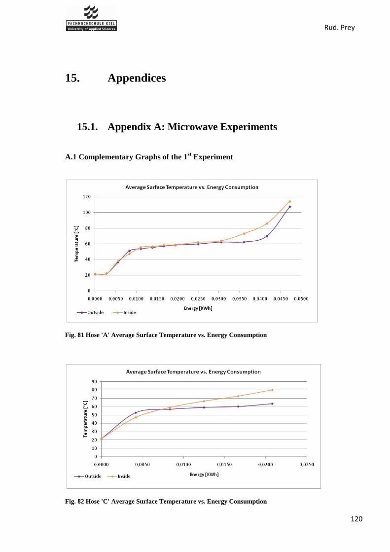
Rud. Prey
120
15. Appendices
15.1. Appendix A: Microwave Experiments
A.1 Complementary Graphs of the 1st Experiment
Fig. 81 Hose 'A' Average Surface Temperature vs. Energy Consumption
Fig. 82 Hose 'C' Average Surface Temperature vs. Energy Consumption

Rud. Prey
121
A.2 Complementary Graphs of the 2nd
Experiment
Fig. 83 Hose 'B' Mass Loss vs. Energy Consumption
Fig. 84 Hose 'D' Mass Loss vs. Energy Consumption

Rud. Prey
122
A.3 Interpretation of the Graph: Microwave Power vs. Operating Speed.
The result, at first glance, is strange because the speed of the hose does not depend of the size
(in meters) of the microwave. The below explanation will clarify this:
In both cases we considered:
Microwave power: 1kW
Process speed: 1m/s
These numbers are used just as an example for explaination.
Case 1. Size of the Hose in Microwave: 4m
In this case, 4m of hose are in the microwave at the same time, and each 1m section of hose
does not receive 1kW, but only 250W (1000/4) and this exposure is for 4s. Therefore, the
piece receives:

Rud. Prey
123
Case 2. Size of the Hose in Microwave: 1m
In this case 1m is in the microwave so:
Thus, the size does not influence the speed for a given powered microwave.

Rud. Prey
124
15.2. Appendix B: Infrared Experiments
B.1 Complementary graphs of the 1st experiment:
Fig. 85 Average Surface Temperature vs. Energy Consumption, IR
Fig. 86 Mass Loss vs. Energy Consumption, IR

Rud. Prey
125
B.2 Complementary graphs of the 2nd
experiment:
Fig. 87 Average Surface Temperature vs. Energy Costs, IR with Hair Dryer
Fig. 88 Mass Loss vs. Energy Consumption, IR with Hair Dryer

Rud. Prey
126
15.3. Appendix C: Fire Department Visit Notes
C.1 FTZ in Steinburg
Date: 8 April 2010
We visited the fire department in Steinburg where they train new fire fighters. They use the
drying system for all hoses of fire departments around Steinburg. They use the Hanging
system of Rud.Prey to dry with a maintenance system to clean and test.
Use:
6000 hoses of 103 fire departments
Easy to use and to understand how it works so easy to find where comes from a
problem
Working time:
2/3 days to dry in summer
1/1.5 weeks to dry in winter (with a system to heat air)
10 min working time (without drying time)
Hoses:
17 lanes, 22B or 25 C hoses per lane
Approximately 400 hoses
Maintenance:
One time per year
More at the beginning because of small problems
Safety:
Hose can fall down when a push arm sensor is broken or if adapters aren‟t use right
Prize:
35000€ (+taxes): hanging + maintenance

Rud. Prey
127
Positive things:
Fast
Cheap to dry
Possible to leave a lot of hoses in the same time
Negative things:
Dangerous sometimes
Improvements:
Maintenance sheet in the middle of hanging device for use all the lanes quickly
Roll

Rud. Prey
128
C.2 Main Fire Department in Kiel
Date: 19 April 2010
Global information:
Automatic hanging system from Hafenrichter
Hose capacity in all Kiel fire dep. and trucks:
o Approx. 1200 B hoses +- 50
o Approx. 1200 C hoses +- 50
o Seven 35 meter hoses for ladders (it is not allowed to have a coupling on the
ladder, this is why these hoses are so long)
o Time for washing = time for hanging hose up
Maintenance system (horizontal street):
Maintenance street for up to 20 m long hoses ( B-hoses)
Day capacity for maintenance process: up to 80 hoses per 8-h-day
Pressure testing at 12 bar for 2-3 minutes ( will be updated to 16 bar)
Breaking of the hose:
o 80 % breaks near to the coupling
o Rest: damage in hose itself because of pre-damages when a car drives over the
hose or it is pulled trough fire or broken glass
Water for pressure testing is used for approx. 4 weeks (is stored in two 50 litter basins
under the maintenance. street)
Automatic hanging system:
Full tower (25 m high) for up to 140 hoses
14 lanes (10 B hoses or 13 C hoses per lane)
Adaptor just for transporting the hose, in lane it hangs on coupling
3 or 4 days for drying (depends of the weather etc.)
In winter: heater for warm up the air, but needs a lot of energy
For ventilation: 2 windows can be open at the top of tower and 2 doors on the floor
(manual opening/closing)

Rud. Prey
129
Maintenance interval: 1 time / year
If something is broken they repair it themselves (time to get service from company:
approx. 4 weeks)
What brakes in this system?
Adaptor is not well positioned in the positioning pipe of the crane –> pos. pipe
deforms
Fire hoses:
B hose: 75 mm of diameter
C hose: 42 or 52 mm of diameter, but in future only 42 mm of hoses, because it is
easier to handle for the fire fighter
Bright yellow as new color for the hoses, because it is easier to see at night
Difference between wet and dry hose: approx. 1 kg -> textile fabric don‟t absorb much
water
For hose material it is not bad to be rolled up or stored wet, but it starts to smell if
there is not enough ventilation
Approx. 50 to 100 hoses gets broken per year
Hose life time is up to 30 years
Hose basket:
3 C hoses inside, clutched together
Fix top end of hose and run -> hoses unfold themselves out of the basket
Easy and fast way to lay out hoses
Improvements:
Maintenance street:
o You cannot stop the running process (4-edge-program)
o Wagon for pulling the hoses drives always till the end of the street to stop the
washing machine (even if the hose is just 5 meter long…)
o Wagon takes 2 minutes to drive from end to start of street
o You cannot change the speed of the wagon
Hanging system:
Rud. Prey
130
o Positioning system in the crane takes too long
o Fire department has idea to make it faster, but if they do it, they would lose the
warranty for the system
o For folding the hose at the half:
- Push button when hose touches the ground so system knows the length of it
- Let hose more down to the half and roll it up doubled
- Problem: imprecise for 10 to 15 cm
Fire fighting cars:
Special cars:
o Container system -> easy and fast to equip the cars (3 minutes)
o Container for heavy load (including a crane) for car crashs, trees etc., chemical
accidents,
Standard fire fighting cars:
o Fire extinguishing cars with 2000 litter water basin, 6 persons
o With ladder, 2 persons
o Leading car, 2 persons
o Standardized packing system for all of the equipment in every car in Kiel
Miscellaneous:
Costs for maintenance street + hanging system: approx. 100,000 Euro
Additional use of tower as radio station for fire fighting cars and mobile phones
6 years ago: Prey system, but it was too old -> new system -> open tendering for new
system -> Hafenrichter was cheaper than Prey so they get the assignment
Old Prey system hold more than 200 C hoses
For becoming a fire fighter you first have to do an apprenticeship as metalworker,
electrician, mechanician

Rud. Prey
131
C.3 FTZ in Zeven
Date: 27 May 2010
Drying system: Horizontal Process Dryer for 4 hoses
Cost of Machine: 5000€
Maintenance: once/year, pay extra
Personal Comments:
Ease of operation, Comfort, and Safety are very good
Problem is the noise (78dB)
o Insulation box for water pump (pressure testing) to reduce
o Suggestion to have pumps and loud machines in different room
Only twice the roll-up device has broken
o Overall is a positive
o Shorter drying time
Filling hoses with water up to 3 bar takes too long
Test Pressure: 12bar
Drying Time:
10-15min – new hoses
20-30min – old hoses
Air Temperature while drying: 60°C
155 Fire Departments in Area:
4000 hoses total
5500-6000 maintained per year
Hoses Dried/day:
35-40 – old hoses / Up to 80 – new hoses

Rud. Prey
132
15.4. Appendix D: Company Documents
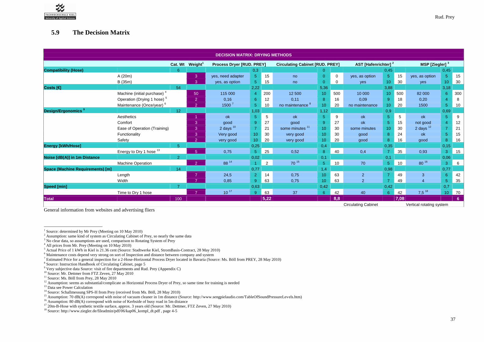
Rud. Prey
37
5.9 The Decision Matrix
General information from websites and advertising fliers
1 Source: determined by Mr Prey (Meeting on 10 May 2010)
2 Assumption: same kind of system as Circulating Cabinet of Prey, so nearly the same data
3 No clear data, so assumptions are used, comparison to Rotating System of Prey
4 All prices from Mr. Prey (Meeting on 10
May 2010)
5 Actual Price of 1 kWh in Kiel is 21.36 cent (Source: Stadtwerke Kiel, StromBasis-Contract, 28 May 2010)
6 Maintenance costs depend very strong on sort of Inspection and distance between company and system
7 Estimated Price for a general inspection for a 2-Hose-Horizontal Process Dryer located in Bavaria (Source: Ms. Böll from PREY, 28 May 2010)
8 Source: Instruction Handbook of Circulating Cabinet, page 5
9 Very subjective data Source: visit of fire departments and Rud. Prey (Appendix C)
10 Source: Mr. Dettmer from FTZ Zeven, 27 May 2010
11 Source: Ms. Böll from Prey, 28 May 2010
12 Assumption: seems as substantial/complicate as Horizontal Process Dryer of Prey, so same time for training is needed
13 Data see Power Calculation
14 Source: Schallmessung SPS-H from Prey (received from Ms. Böll, 28 May 2010)
15 Assumption: 70 dB(A) correspond with noise of vacuum cleaner in 1m distance (Source: http://www.sengpielaudio.com/TableOfSoundPressureLevels.htm)
16 Assumption: 80 dB(A) correspond with noise of Kerbside of busy road in 5m distance
17 20m-B-Hose with synthetic textile surface, approx. 3 years old (Source: Mr. Dettmer, FTZ Zeven, 27 May 2010)
18 Source: http://www.ziegler.de/fileadmin/pdf/06/kap06_kompl_dt.pdf , page 4-5
DECISION MATRIX: DRYING METHODS
Cat. Wt Weight1 Process Dryer [RUD. PREY] Circulating Cabinet [RUD. PREY] AST [Hafenrichter]
2 MSP [Ziegler]
3
Compatibility (Hose) 6 0,3 0 0,45 0,45
A (20m) 3 yes, need adapter 5 15 no 0 0 yes, as option 5 15 yes, as option 5 15
B (35m) 3 yes, as option 5 15 no 0 0 yes 10 30 yes 10 30
Costs [€] 54 2,22 5,36 3,88 3,18
Machine (initial purchase) 4 50 115 000 4 200 12 500 10 500 10 000 10 500 82 000 6 300
Operation (Drying 1 hose) 5 2 0,16 6 12 0,11 8 16 0,09 9 18 0,20 4 8
Maintenance (Once/year) 6 2 1500
7 5 10 no maintenance
8 10 20 no maintenance 10 20 1500 5 10
Design/Ergonomics 9 12 1,03 1,12 0,9 0,69
Aesthetics 1 ok 5 5 ok 5 9 ok 5 5 ok 5 9
Comfort 3 good 9 27 good 9 27 ok 5 15 not good 4 12
Ease of Operation (Training) 3 2 days 10
7 21 some minutes 11
10 30 some minutes 10 30 2 days 12
7 21
Functionality 3 Very good 10 30 very good 10 30 good 8 24 ok 5 15
Safety 2 very good 10 20 very good 10 20 good 8 16 good 8 16
Energy [kWh/Hose] 5 0,25 0,4 0,35 0,15
Energy to Dry 1 hose 13
5 0,75 5 25 0,52 8 40 0,4 7 35 0,93 3 15
Noise [dB(A)] in 1m Distance 2 0,02 0,1 0,1 0,06
Machine Operation 2 88 14
1 2 70 15
5 10 70 5 10 80 16
3 6
Space (Machine Requirements) [m] 14 0,77 1,4 0,98 0,77
Length 7 24,5 2 14 0,75 10 63 2 7 49 3 6 42
Width 7 0,85 9 63 0,75 10 63 2 7 49 4 5 35
Speed [min] 7 0,63 0,42 0,42 0,7
Time to Dry 1 hose 7 10 17
9 63 37 6 42 40 6 42 7,5 18
10 70
Total 100 5,22 8,8 7,08 6
Circulating Cabinet Vertical rotating system
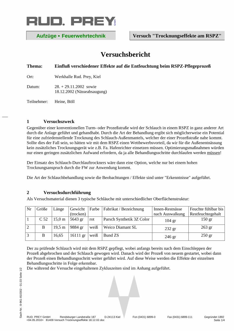
RUD. PREY GmbH Rendsburger Landstraße 187 D-24113 Kiel Fon (0431) 6899-0 Fax (0431) 6899-111 Gegründet 1892 Seite 1/4
Gm
bH
Sac
h-N
r.: 8
-961
-810
302
- 01
.03
Sei
te 1
/2
<04.05.2010> 81409 Versuch Trocknungseffekte 18.12.02.doc
Aufzüge •••• Feuerwehrtechnik Versuch "Trocknungseffekte am RSPZ"
Versuchsbericht Thema: Einfluß verschiedener Effekte auf die Entfeuchtung beim RSPZ-Pflegeprozeß Ort: Werkhalle Rud. Prey, Kiel Datum: 28. + 29.11.2002 sowie 18.12.2002 (Nässeabsaugung) Teilnehmer: Heine, Böll
1 Versuchszweck Gegenüber einer konventionellen Turm- oder Prozeßstraße wird der Schlauch in einem RSPZ in ganz anderer Art durch die Anlage geführt und gehandhabt. Durch die Art der Behandlung ergibt sich möglicherweise ein Potential für eine zufriedenstellende Trocknung des Schlauch-Außenmantels, welcher der einer Prozeßstraße nahe kommt. Sollte dies der Fall sein, so hätten wir mit dem RSPZ einen Wettbewerbsvorteil, da wir für die Außenentnässung kein zusätzliches Trocknungsgerät wie z.B. Fa. Hafenrichter einsetzen müssen. Optimierungsmaßnahmen würden nur einen geringen zusätzlichen Aufwand erfordern, da ja alle Behandlungsschritte durchlaufen werden müssen! Der Einsatz des Schlauch-Durchlauftrockners wäre dann eine Option, welche nur bei einem hohen Trocknungsanspruch durch die FW zur Anwendung kommt. Die Art der Schlauchbehandlung sowie die Beobachtungen / Effekte sind unter "Erkenntnisse" aufgeführt.
2 Versuchsdurchführung Als Versuchsmaterial dienen 3 typische Schläuche mit unterschiedlicher Oberflächenstruktur: Nr Größe Länge Gewicht
(trocken) Farbe Fabrikat / Bezeichnung Innen-Restnässe
nach Auswalkung Feuchte fühlbar bis Restfeuchtegehalt
1 C 52 15,0 m 5643 gr rot Parsch Synthetik 3Z Color 104 gr 150 gr
2 B 19,5 m 9884 gr weiß Weico Diamant SL 232 gr 263 gr
3 B 16,65 16111 gr weiß Bund ZS 246 gr 250 gr
Der zu prüfende Schlauch wird mit dem RSPZ gepflegt, wobei anfangs bereits nach dem Einschleppen der Prozeß abgebrochen und der Schlauch gewogen wird. Danach wird der Prozeß von neuem gestartet, wobei dann der Prozeß einen Behandlungsschritt weiter geführt wird. Auf diese Weise werden die Effekte der einzelnen Behandlungsschritte in Folge erkennbar. Die während der Versuche eingehaltenen Zykluszeiten sind im Anhang aufgeführt.

Versuch "Trocknungseffekte am RSPZ"
<04.05.2010> 81409 Versuch Trocknungseffekte 18.12.02.doc Seite 2/4
Sac
h-N
r.: 8
-961
-810
302
- 01
.03
Sei
te 2
/2
3 Erkenntnisse Die Restfeuchtigkeit wurde durch wiegen des Schlauchmaterials erfaßt. Bei den angegebenen Gewichten ist zu beachten, daß die Wiederholgenauigkeit zwischen mehreren gleichartigen Prozessen bei ±15 gr liegt. Die in obiger Tabelle angegebene Innennässe nach dem Auswalken wurde durch Differenzwägung mit zwischengeschalteter Innentrocknung ermittelt. Die nachfolgenden Behandlungsweisen haben folgenden Effekt auf die Mantelentnässung:
3.1 Schlauch steht senkrecht Der Schlauch wird nach dem Vorweichen in eine senkrechte Position gedreht. Die Nässe kann nicht auf dem Mantel stehenbleiben. Dieser Behandlungsschritt ist der Ausgangspunkt für die weiteren Effekte.
3.2 Nässe wird in SWM nach unten abgefeuert Wie bei 3.1 ist das Saugvermögen des Gewebe-Schlauchmantels maßgeblich für den Effekt. Bei dem nur wenig saugfähigen Schlauch Nr. 2 wird eine geringfügige Entnässung gegenüber 3.1 beobachtet. Bei den Schläuchen Nr.1) und 3) tritt eine Befeuchtung auf. Fazit: Effekt vernachlässigbar klein!
3.3 Auswalkeinrichtung mit leerem Schlauch Gegenüber den vorangegangenen Behandlungsschritten tritt bei allen Schläuchen nur eine geringfügige Entnässung knapp über der Wiederholgenauigkeit auf. Fazit: Effekt vernachlässigbar klein!
3.4 Auswalkeinrichtung mit gefülltem Schlauch Die Schläuche Nr. 1) und 2) weisen eine Gewichtszunahme von 130 gr (C-Schlauch) bzw. 45 gr (B-Schlauch) auf. Diese ist jedoch auf die Vergrößerung der Innen-Nässe zurückzuführen. Beim saugfähigen Schlauch Nr. 3 ist eine Gewichtsabnahme zu notieren, obwohl hier die Innennässe höher sein dürfte. Bei allen Schläuchen läßt sich etwas stauende Nässe vor der Auswalkrolle – und zwar nur im unteren Schlauchdrittel – beobachten. Diese kann nicht schnell genug und nicht vollständig nach unten ablaufen. Die Nässe wird mit um die Auswalkrolle gezogen. Nur beim Schlauch Nr. 3) ist die Wassermenge so groß, daß sie in geringer Menge an der Auswalkeinrichtung ablaufen kann. Fazit: Effekt gering!
3.5 Druckprobe mit Auswalkung Steht der Schlauch unter Prüfdruck, dann wird das Außengewebe stark gepreßt. Das enthaltene Wasser gelangt an die Oberfläche und läuft außen teilweise ab. Das nach Außen gepreßte Wasser läßt sich als Wasserfilm bzw. als Tropfen an der Oberfläche beobachten. Die Entnässung beträgt ca. 100g beim C-Schlauch und 200gr beim B-Schlauch (beide Gewebearten!) und übertrifft damit alle im Pflegeprozeß vorangegangenen Effekte. Nach erfolgter Druckprobe läßt sich an der Auswalkrolle auch keine stauende Nässe mehr wie unter 3.4 beobachten. Der von der Auswalkrolle auf den Wickler gezogene Schlauch ist im unteren Drittel fühlbar feuchter als an der Oberkante. Am unter Prüfdruck stehenden Schlauch Nr. 1) wurde exemplarisch die Außennässe mit einem Tuch abgewischt. Die Restfeuchte ließ sich damit um weitere 150 gr. verringern. Hier besteht noch Potential! Fazit: Bedeutender Effekt !

Versuch "Trocknungseffekte am RSPZ"
<04.05.2010> 81409 Versuch Trocknungseffekte 18.12.02.doc Seite 3/4
Sac
h-N
r.: 8
-961
-810
302
- 01
.03
Sei
te 2
/2
3.6 Druckprobe ohne Auswalken An Stelle der Auswalkeinrichtung wurde der Schlauch hier nur auf den Wickler umgelenkt. Bei allen Schläuchen wird eine Gewichtszunahme notiert, welche die positive Wirkung des Effektes 3.4 wieder aufhebt. Diese Gewichtszunahme liegt in der Erhöhung der Innennässe begründet. Fazit: Effekt Nachteilig!
3.7 Absaugeinrichtung Es kam eine verbesserte Absaugdüse zum Einsatz, welche optimal kleine Saugspalte gewährleistet. Somit bleibt ein hoher Unterdruck während des Absaugens erhalten. Die zwischen Schlauch und Düse einströmende Luft hat damit immer eine maximale Geschwindigkeit und kann dadurch die Feuchtigkeit aus der obersten Gewebeschicht mitreißen. Gegenüber 3.5 läßt sich die dort vorhandene Restfeuchte um weitere ca. 10% vermindern - beim saugfähigen Schlauch Nr. 3) sogar um 20%! Dies entspricht der dortigen Wirkung des "Außen-Abwischens" unter Prüfdruck. Eine Halbierung der Zuggeschwindigkeit während des Absaugens bringt nur eine Verbesserung in Größenordnung der Meßgenauigkeit. Der Trocknungseffekt der Absaugung ist bei praxisgerechten Zuggeschwindigkeiten hauptsächlich von der Außenfeuchte des Schlauchmantels abhängig. Der Effekt der Absaugung überdeckt den der Druckprobe unter 3.5! Fazit: Bedeutender Effekt!
3.8 Nachtrockenstrecke Die Erprobung wird wegen folgender theoretischen Überlegungen verworfen: Bei einer Heißluftbeaufschlagung wird das Wasser durch Verdunstung abgeführt. Die Verdunstungswärme muß dem Schlauch zwischen Auswalkeinrichtung und Wickler über die Heißluft zugeführt werden. Dabei wird dem ca. 1m langen Schlauchstück eine Wärme von Q = α × A × (T1 – T2) Q= 30 × 0,15 × (70 – 15) Q= 396 W ( J/s)
mit : α = 30 W/m²×K Wärmeübergangszahl A = 0,12m×1m×2 = 0,24 m² Schlauchoberfläche T1= 70°C Heißlufttemperatur T2= 15°C Schlauchoberflächentemp.
zugeführt. Unter der Voraussetzung, daß der Herauszieh- /Auswalk- und Trocknungsprozeß 60 Sekunden dauert, läßt sich mit dieser Wärme während dieser Zeit im Idealfall folgende Wassermenge verdunsten: m = Q × t cP
m = 396 J/s × 60 s 2.500.000 J/kg m = 0,0095 kg (9,5 gr)
mit: Q = auf den Schlauch übertragene Wärme (s.o.) t = Trocknungszeit cP = 2.500.000 J/kg Verdunstungswärme von Wasser
Bei dieser stark vereinfachten Rechenweise sind weitere negative Einflüsse wie die Erwärmung des Schlauchmaterials und des Wassers, noch gar nicht berücksichtigt! Hauptursache der geringen Trocknungsleistung ist die kleine heißluftbeaufschlagte Schlauchoberfläche. Fazit: Ungeeignet!. Hoher Aufwand, geringe Wirkung!
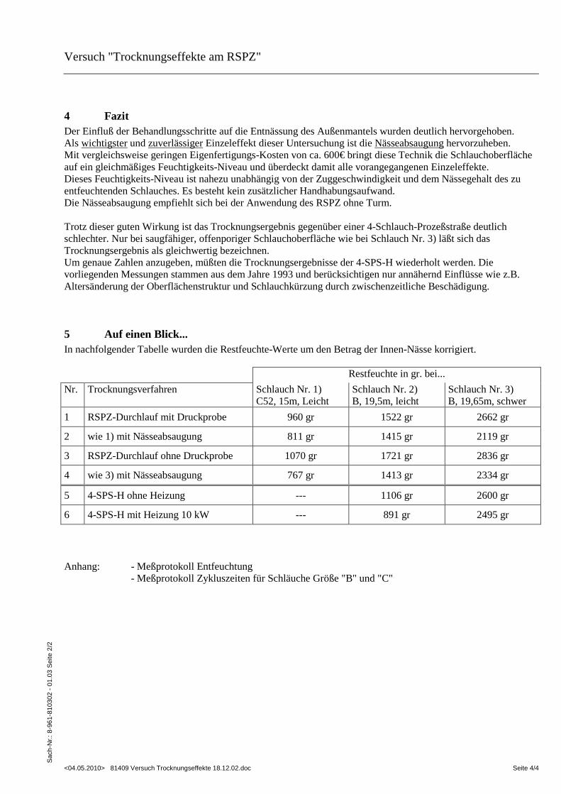
Versuch "Trocknungseffekte am RSPZ"
<04.05.2010> 81409 Versuch Trocknungseffekte 18.12.02.doc Seite 4/4
Sac
h-N
r.: 8
-961
-810
302
- 01
.03
Sei
te 2
/2
4 Fazit Der Einfluß der Behandlungsschritte auf die Entnässung des Außenmantels wurden deutlich hervorgehoben. Als wichtigster und zuverlässiger Einzeleffekt dieser Untersuchung ist die Nässeabsaugung hervorzuheben. Mit vergleichsweise geringen Eigenfertigungs-Kosten von ca. 600€ bringt diese Technik die Schlauchoberfläche auf ein gleichmäßiges Feuchtigkeits-Niveau und überdeckt damit alle vorangegangenen Einzeleffekte. Dieses Feuchtigkeits-Niveau ist nahezu unabhängig von der Zuggeschwindigkeit und dem Nässegehalt des zu entfeuchtenden Schlauches. Es besteht kein zusätzlicher Handhabungsaufwand. Die Nässeabsaugung empfiehlt sich bei der Anwendung des RSPZ ohne Turm. Trotz dieser guten Wirkung ist das Trocknungsergebnis gegenüber einer 4-Schlauch-Prozeßstraße deutlich schlechter. Nur bei saugfähiger, offenporiger Schlauchoberfläche wie bei Schlauch Nr. 3) läßt sich das Trocknungsergebnis als gleichwertig bezeichnen. Um genaue Zahlen anzugeben, müßten die Trocknungsergebnisse der 4-SPS-H wiederholt werden. Die vorliegenden Messungen stammen aus dem Jahre 1993 und berücksichtigen nur annähernd Einflüsse wie z.B. Altersänderung der Oberflächenstruktur und Schlauchkürzung durch zwischenzeitliche Beschädigung.
5 Auf einen Blick... In nachfolgender Tabelle wurden die Restfeuchte-Werte um den Betrag der Innen-Nässe korrigiert. Restfeuchte in gr. bei...
Nr. Trocknungsverfahren Schlauch Nr. 1) C52, 15m, Leicht
Schlauch Nr. 2) B, 19,5m, leicht
Schlauch Nr. 3) B, 19,65m, schwer
1 RSPZ-Durchlauf mit Druckprobe 960 gr 1522 gr 2662 gr
2 wie 1) mit Nässeabsaugung 811 gr 1415 gr 2119 gr
3 RSPZ-Durchlauf ohne Druckprobe 1070 gr 1721 gr 2836 gr
4 wie 3) mit Nässeabsaugung 767 gr 1413 gr 2334 gr
5 4-SPS-H ohne Heizung --- 1106 gr 2600 gr
6 4-SPS-H mit Heizung 10 kW --- 891 gr 2495 gr
Anhang: - Meßprotokoll Entfeuchtung - Meßprotokoll Zykluszeiten für Schläuche Größe "B" und "C"