design principles that are involved in the design of flow over an ogee crest spillway ·...
TRANSCRIPT
International Journal of Science and Research (IJSR) ISSN: 2319-7064
ResearchGate Impact Factor (2018): 0.28 | SJIF (2018): 7.426
Volume 8 Issue 8, August 2019
www.ijsr.net Licensed Under Creative Commons Attribution CC BY
Design Principles that are involved in the Design of
Flow over an Ogee Crest Spillway
Venkata Raju Badanapuri
Executive Engineer, Water Resources Department, Government of Andhra Pradesh, India
Abstract: The ogee-crested spillway’s ability to pass flows efficiently and safely, when properly designed and constructed, with
relatively good flow measuring capabilities, has enabled engineers to use it in a wide variety of situations as a water discharge structure
(USACE, 1988; USBR, 1973). The ogee-crested spillway’s performance attributes are due to its shape being derived from the lower
surface of an aerated nappe flowing over a sharp-crested weir. The ogee shape results in near-atmospheric pressure over the crest
section for a design head. At heads lower than the design head, the discharge is less because of crest resistance. At higher heads, the
discharge is greater than an aerated sharp-crested weir because the negative crest pressure suctions more flow. The spillway is among
the most important structures of a dam project. It provides the project with the ability to release excess or flood water in a controlled or
uncontrolled manner to ensure the safety of the project. It is of paramount importance for the spillway facilities to be designed with
sufficient capacity to avoid overtopping of the dam, especially when an earth fill or rockfill type of dam is selected for the project. In
cases where safety of the inhabitants downstream is a key consideration during development of the project, the spillway should be
designed to accommodate the probable maximum flood. Many types of spillways can be considered with respect to cost, topographic
conditions, dam height, foundation geology, and hydrology. In this study, the ogee-crested spillway’s or overflow spillways discussed in
this paper. A section on design of spillways that considers cavitation and aeration.
Keywords: ogeecrested spillway, dam height, design head, discharge, spillway crest profile
1. Introduction
Spillway is a passage in a dam through which the design
flood could be disposed off safely to the downstream. The
ogee-crested spillway, because of its superb hydraulic
characteristics, has been one of the most studied hydraulic
structures. Its ability to passflows efficiently and safely,
when properly designed, with relatively good flow
measuring capabilities, has enabled engineers to use it in a
wide variety of situations. Although much is understood
about the general ogee shape and its flow characteristics, it
is also understood that a deviation from the standard design
parameters such as a change inupstream flow conditions,
slightly modified crest shape, or construction variances
canchange the flow properties. These small changes often
require engineers to evaluatethe crest and determine whether
or not the change or deviation will be detrimental to the
spillway's performance. Such is the case when an updated
probable maximum flood calculation requires a spillway to
pass a larger flow than it was designed to handle. In general,
spillways comprise five distinct components namely: (i) an
entrance channel,(ii) a control structure, (iii) a discharge
carrier, (iv) an energy dissipator, and (v) an outlet channel.
The entrance channel transfers water from the reservoir to
the control structure, which regulates the discharge from the
reservoir. Water is then conveyed from reservoir to the low-
level energy dissipator on the riverbed by the discharge
conveyor. An energy dissipator is required to reduce the
high velocity of the flow to an on scouring magnitude. Most
common types of spillway-control system used are roller,
tainter, vertical-lift, and drum gates. In view of the varying
conditions, the choice of suitable gate is bound by thecost,
the head on the crest, the height of dam, and the hydraulic
behaviour of the gate.Piers are located on the spillway crest
for the purpose of supporting the control gates,the gate-
operating mechanisms or a roadway. Their size and shape
will vary accordingly with their function. The piers should
be streamlined both in the upstreamand the downstream
sides to reduce contraction of the overflowing jet and to
provide asmooth water surface.The element which
introduces the energy-reducing action is generally known as
"stilling basin." One of the most common methods out of
several methods are dissipating theflow at the toe of a
spillway, is the hydraulic jump. Other types used in
conjunction with spillways are roller and trajectory buckets.
Spillway outlets means the combination ofstructures and
equipment required for the safe operation and control of the
waterreleased for different purposes for which the dam is
planned. These structures may beriver outlets, penstocks,
canal outlets. The size and number of river outlets satisfy the
discharge requirements at various stages of the reservoir. If
the outlets are located inthe overflow portion, the conduits
should be aligned downwards to minimise disturbanceto the
flow over spillway. The discharge from an outlet, (gates,
valves, or free-flow conduits) has a relatively high velocity.
Flow must expend the energy in order to preventscour of the
bed and banks of the river channel. This may be
accomplished byconstructing a stilling basin immediately
downstream from the outlet.The crest of the spillway is
usually provided at F.R.L (Full Reservoir Level). However,
inorder to control floods, the gates could be provided at the
top and the water level could be increased up to maximum
water level. The height between F.R.L and M.W.L is
calledthe "Flood lift". Reservoir level should not cross
MWL. Following are different types ofspillways usually
adopted in practice.
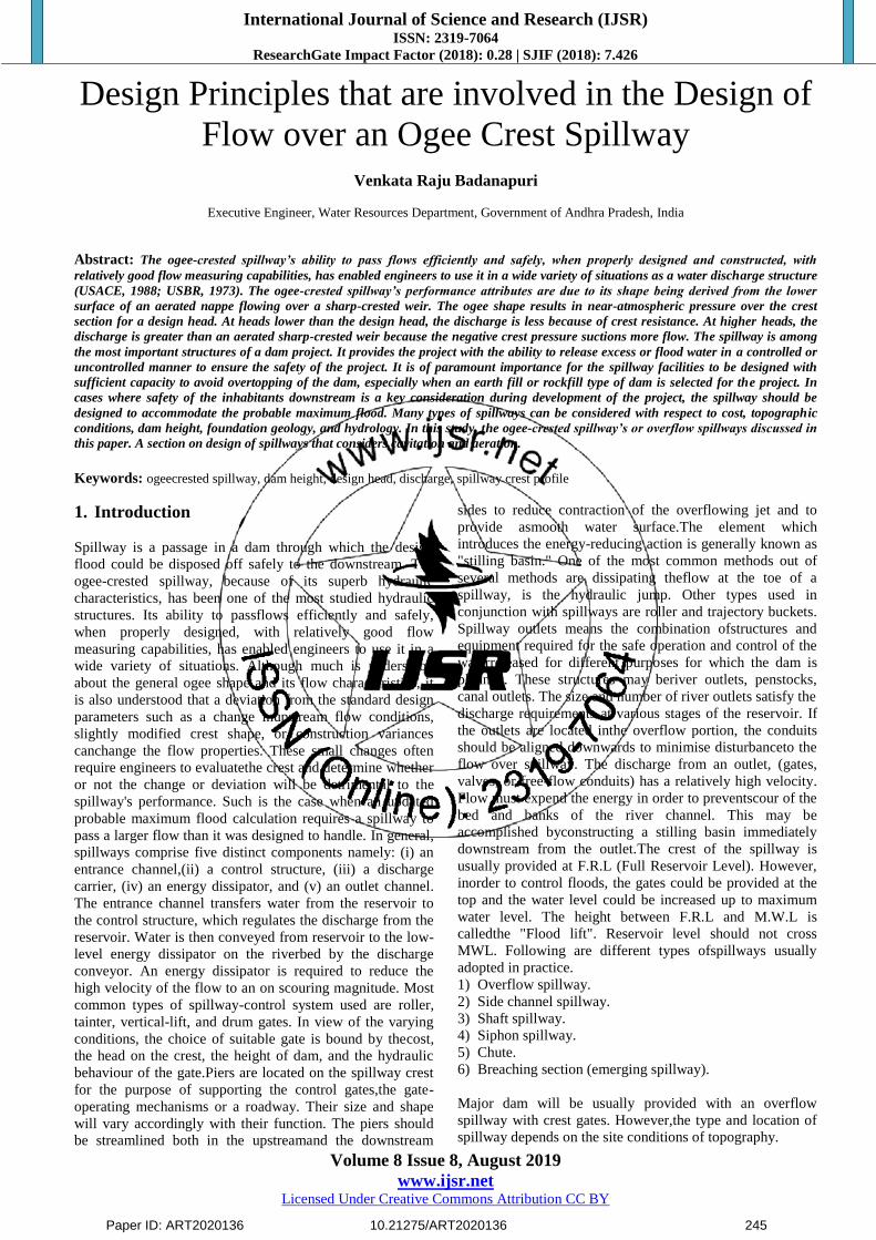
1) Overflow spillway.
2) Side channel spillway.
3) Shaft spillway.
4) Siphon spillway.
5) Chute.
6) Breaching section (emerging spillway).
Major dam will be usually provided with an overflow
spillway with crest gates. However,the type and location of
spillway depends on the site conditions of topography.
Paper ID: ART2020136 10.21275/ART2020136 245
International Journal of Science and Research (IJSR) ISSN: 2319-7064
ResearchGate Impact Factor (2018): 0.28 | SJIF (2018): 7.426
Volume 8 Issue 8, August 2019
www.ijsr.net Licensed Under Creative Commons Attribution CC BY
1.1 Necessity of Spillways
The height of the dam is always fixed according to the
maximum reservoir capacity. The normal pool level
indicates the maximum capacity of the reservoir. The water
is never stored in the reservoir above this level. The dam
may fail by overturning so, for the safety of the dam the
spillways are essential.The top of the dam is generally
utilized by making road. The surplus water is not be allowed
to over top the dam, so to stop the over topping by the
surplus water, the spillways become extremely essential.To
protect the downstream base and floor of the dam from the
effect of scouring and erosion, the spillways are provided so
that the excess water flows smoothly.
1.2 Location of a Spillway
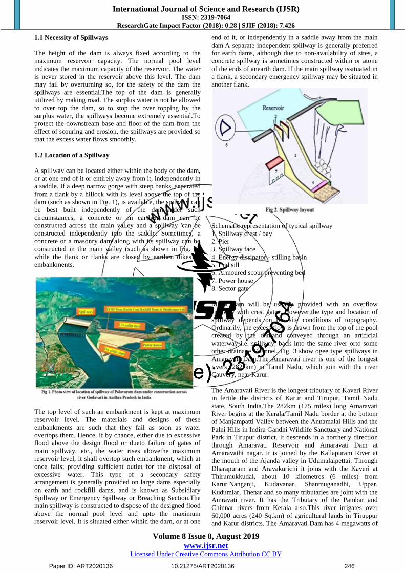
A spillway can be located either within the body of the dam,
or at one end of it or entirely away from it, independently in
a saddle. If a deep narrow gorge with steep banks, separated
from a flank by a hillock with its level above the top of the
dam (such as shown in Fig. 1), is available, the spillway can
be best built independently of the dam.Under such
circumstances, a concrete or an earthen dam can be
constructed across the main valley and a spillway 'can be
constructed independently into the saddle. Sometimes, a
concrete or a masonry dam along with its spillway can be
constructed in the main valley (such as shown in Fig. 2),
while the flank or flanks are closed by earthen dikes or
embankments.
The top level of such an embankment is kept at maximum
reservoir level. The materials and designs of these
embankments are such that they fail as soon as water
overtops them. Hence, if by chance, either due to excessive
flood above the design flood or dueto failure of gates of
main spillway, etc., the water rises abovethe maximum
reservoir level, it shall overtop such embankment, which at
once fails; providing sufficient outlet for the disposal of
excessive water. This type of a secondary safety
arrangement is generally provided on large dams especially
on earth and rockfill dams, and is known as Subsidiary
Spillway or Emergency Spillway or Breaching Section.The
main spillway is constructed to dispose of the designed flood
above the normal pool level and upto the maximum
reservoir level. It is situated either within the darn, or at one
end of it, or independently in a saddle away from the main
dam.A separate independent spillway is generally preferred
for earth dams, although due to non-availability of sites, a
concrete spillway is sometimes constructed within or atone
of the ends of anearth dam. If the main spillway issituated in
a flank, a secondary emergency spillway may be situated in
another flank.
Schematic representation of typical spillway
1. Spillway crest / bay
2. Pier
3. Spillway face
4. Energy dissipator - stilling basin
5. End sill
6. Armoured scour preventing bed
7. Power house
8. Sector gate
Major dam will be usually provided with an overflow
spillway with crest gates. However,the type and location of
spillway depends on the site conditions of topography.
Ordinarily, the excess flow is drawn from the top of the pool
created by the damand conveyed through an artificial
waterway i.e. spillway, back into the same river orto some
other drainage Channel. Fig. 3 show ogee type spillways in
Amaravati Dam.The Amaravati river is one of the longest
rivers (282 km) in Tamil Nadu, which join with the river
Cauvery, near Karur.
The Amaravati River is the longest tributary of Kaveri River
in fertile the districts of Karur and Tirupur, Tamil Nadu
state, South India.The 282km (175 miles) long Amaravati
River begins at the Kerala/Tamil Nadu border at the bottom
of Manjampatti Valley between the Annamalai Hills and the
Palni Hills in Indira Gandhi Wildlife Sanctuary and National
Park in Tirupur district. It descends in a northerly direction
through Amaravati Reservoir and Amaravati Dam at
Amaravathi nagar. It is joined by the Kallapuram River at
the mouth of the Ajanda valley in Udumalaipettai. Through
Dharapuram and Aravakurichi it joins with the Kaveri at
Thirumukkudal, about 10 kilometres (6 miles) from
Karur.Nanganji, Kudavanar, Shanmuganadhi, Uppar,
Kudumiar, Thenar and so many tributaries are joint with the
Amravati river. It has the Tributary of the Pambar and
Chinnar rivers from Kerala also.This river irrigates over
60,000 acres (240 Sq.km) of agricultural lands in Tiruppur
and Karur districts. The Amaravati Dam has 4 megawatts of
Paper ID: ART2020136 10.21275/ART2020136 246

International Journal of Science and Research (IJSR) ISSN: 2319-7064
ResearchGate Impact Factor (2018): 0.28 | SJIF (2018): 7.426
Volume 8 Issue 8, August 2019
www.ijsr.net Licensed Under Creative Commons Attribution CC BY
electricity generating capacity installed. The Amaravati
River and its basin, especially in the vicinity of Karur, are
heavily used for industrial processing water and waste
disposal and as a result are severely polluted due to large
amount of textile dyeing and bleaching units. But nowadays
in karur, the changes are vicinity by seeing Amaravati river
on its clean surface because of pollution controlled by
government.
1.3 Design Considerations for the Main Spillway
The main spillway, often called the spillway, is properly
designed so as to dispose of theexcess waterwithout causing
anydamage to the dam, or to any of its appurtenant
structures. The spillway structure should be structurally and
hydraulically adequate and must not give way under worst
and variable loading conditions.The required discharging
capacity, of the spillway should be as closely estimated as
possible. The underestimation will lead to overtopping of the
main dam and its consequent damages; while the over
estimation will lead to unnecessarily costly constructions
which shall never, be utilised during the life of the dam, and
hence, will remain a waste investment. However, on large
dams, a conservative view is always preferred because the
failure of a single dam due to inadequate capacity may result
in the loss of numerous human lives to which no cost
allocation can be made. Moreover, an emergency spillway
or a breaching section is generally provided, the failure of
which under necessary circumstances, may though cause
serious erosion on the downstream, but shall protectthe main
dam from failure.The water passing over the spillway and
falling on the downstream side must not be allowed to erode
the downstream soil, and hence, arrangements must be made
for effectively dissipating the energy of the falling water.
1.4 Classification of Spillways
1) According to the most prominent feature
a) Ogee spillway
b) Chute spillway
c) Side channel spillway
d) Shaft spillway
e) Siphon spillway
f) Straight drop or overfallspillway
g) Tunnel spillway/Culvertspillway
2) According to Function
a) Service spillway
b) Auxiliary spillway
c) Fuse plug or emergencyspillway
3) According to Control Structure
a) Gated spillway
b) Ungated spillway
c) Orifice of sluice spillway
1.5 Spillway Design
(Ogee or Overflow Spillways)
The following aspects are involved in the design of
spillways:
1) Hydrology
A. Estimation of inflow design flood
B. Selection of spillway design flood
C. Determination of spillway outflow discharge
D. Determination of frequency of spillway use
2) Topography and geology
A. Type and location of spillway
3) Utility and operational aspects
A. Serviceability
4) Constructional and structural aspects
A. Cost-effectiveness
1.6 Spillway Design Flood
1) Probable Maximum Flood (PMF)
This is the flood that may be expected from the most severe
combination of critical meteorological and hydrological
conditions thatare reasonably possible in the region. This is
computed by using theProbable Maximum Storm.
2) Standard Project Flood (SPF)
This is the flood that may be expected from the most severe
combination of hydrological and meteorological factors that
areconsidered reasonably characteristic of the region and is
computed byusing the Standard Project Storm (SPS).In US,
generally, large dams are designed for PMF, intermediate
forSPF/PMF, and small dams for floods of return period of
100 years toSPF.The estimation of spillway design flood or
the inflow design flood is anexercise involving diverse
disciplines of hydrology, meteorology,statistics and
probability.There is a great variety of methods used around
the world to determineexceptional floods and their
characteristics. ICOLD (1992) groups allthese methods
under the two main categories:
a) Methods based mainly on flow data.
b) Methods based mainly on rainfall data.
The ogee or overflow spillway is the most common type of
spillway. It has a control weir that is Ogee or S-shaped. It is
a gravity structure requiring sound foundation and is
preferably located in the main riverchannel.
Paper ID: ART2020136 10.21275/ART2020136 247

International Journal of Science and Research (IJSR) ISSN: 2319-7064
ResearchGate Impact Factor (2018): 0.28 | SJIF (2018): 7.426
Volume 8 Issue 8, August 2019
www.ijsr.net Licensed Under Creative Commons Attribution CC BY
1.7 Spillway Components
Spillways generally are made up of four components: a
controlstructure, discharge channel, terminal structure,
andentrance/outlet channels. control structures regulate the
flows from the reservoir into thespillway, ensuring that flow
will not enter the spillway until thewater in the reservoir
reaches the designed level, and moderatingflow into the
spillway once the design level has been reached.Control
structures can be sills, weirs, orifices, or pipes.
Discharge channels, also known as waterways, convey flow
thatpasses through the control structure down to the
streambed below the dam. Note that conveyancestructures
are not always presentin a spillway design; at times
discharge may fall freely afterpassing through the control
structure.
Terminal structures ensure that the flow, which oftentimes
acquires a high velocity whiletraveling down a spillway, will
not cause excessive erosion to the toe of the dam, or any
other nearby structures. Plunge basins, flip buckets, and
deflectors are all examples of terminalstructures.
Entrance channels convey water from a reservoir to the
control structure. Outlet channels conveyflow that has
reached the terminal structure to the river channel that
resides below the dam. Entrance and outlet channels are not
necessarily a component of all spillways; it is possible forthe
spillway to transport flow directly from the reservoir to the
river channel.
1.8 Ogee Spillway Crest Profile
This type of spillway is the most common type adopted in
the field. It divides naturallyinto three zones. Crest, spillway
face and the toe. The concept evolves from replacingthe
lower nappe of the flow over thin plate weir by solid
boundary.
The ogee spillways were being designed in the earlier
periods, in accordance with the theoretical profile obtained
for the lower nape of, a free-falling jet. The profile was
known, as Bazin's profilhe. Theoretically, the adoption of
such a profile, "should cause no negative pressures on
thecrest under designed head. "But in practice, there exists a
lot of friction due to roughness on the surface of the
spillway. Hence, negative pressure on such a profile
seemsinevitable. The presence of negative pressure causes
the danger of cavitation and sometimesfluctuations and
pulsations of the nappe. Hence, while adopting a profile for
thespillway crest, the avoidance of negative pressures must
be an objective along withconsideration of other factors such
as practicability, hydraulic efficiency, stability andeconomy.
Depending upon research work based on these objectives,
various modified·profiles have been proposed these days.
Crest shapes have been studied extensively in the USBR
hydraulic laboratorieswith various approach depths. The
upper and lower nappe surfaces werecarefully measured for
various discharges and velocities of approach. On the
basisof experimental data including Bazin‟s, the Bureau has
developed coordinatesof nappe surfaces for vertical and
upstream sloped weirs. The results are welldocumented in
the USBR publication „Design of Small Dams‟ (1960). The
profilesare defined as they relate to the coordinate axes at
the apex of the crest.The portion upstream of the origin is
defined as a compound circular arc. Theportion downstream
is defined by the equation
On the basis of the USBR data, the US Army Corps of
Engineers, Waterways Experimental Stationin Vicksburg,
(WES) 1952 has developed several standard shapes,
designated as WES standard spillwayshapes, represented on
the downstream of the crest axis by the equation
Where
X and Y are coordinates of crest profile with origin at the
highest point C of the crest, called the apex.
𝐻𝑑design head including velocity head of the approach
flow.K and n are parameters depending on the slope of the
upstream face.The values ofK and n are tabulated in Table
1.0.
Thus, for a spillway having a verticalu/s face, the D/S crest
is given bythe equation
According to the latest studies of the U.S. Army Corps of
Engineersat their' Waterways Experimental Station
(WES),the U/s curve of theogee spillway having a vertical
U/s face, should have the following equation:
Paper ID: ART2020136 10.21275/ART2020136 248
International Journal of Science and Research (IJSR) ISSN: 2319-7064
ResearchGate Impact Factor (2018): 0.28 | SJIF (2018): 7.426
Volume 8 Issue 8, August 2019
www.ijsr.net Licensed Under Creative Commons Attribution CC BY
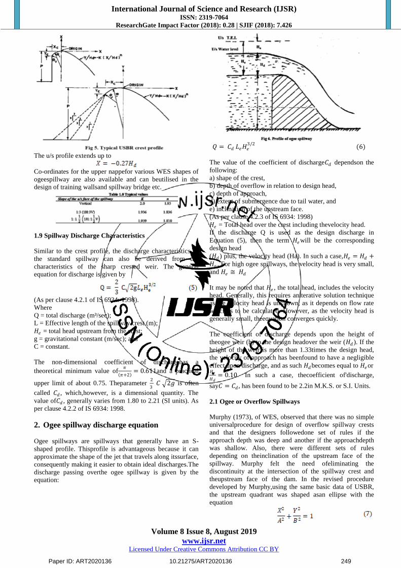
The u/s profile extends up to
Co-ordinates for the upper nappefor various WES shapes of
ogeespillway are also available and can beutilised in the
design of training wallsand spillway bridge etc.
1.9 Spillway Discharge Characteristics
Similar to the crest profile, the discharge characteristics of
the standard spillway can also be derived from the
characteristics of the sharp crested weir. The general
equation for discharge is given by
(As per clause 4.2.1 of IS 6934: 1998).
Where
Q = total discharge (m³/sec);
L = Effective length of the spillway crest (m);
𝐻𝑒 = total head upstream from the crest;
g = gravitational constant (m/sec); and
C = constant.
The non-dimensional coefficient of dischargehas a
theoretical minimum value of𝜋
𝜋+2 = 0.611and a practical
upper limit of about 0.75. Theparameter 2
3 𝐶 2𝑔 is often
called 𝐶𝑑 , which,however, is a dimensional quantity. The
value of𝐶𝑑 , generally varies from 1.80 to 2.21 (SI units). As
per clause 4.2.2 of IS 6934: 1998.
2. Ogee spillway discharge equation
Ogee spillways are spillways that generally have an S-
shaped profile. Thisprofile is advantageous because it can
approximate the shape of the jet that travels along itssurface,
consequently making it easier to obtain ideal discharges.The
discharge passing overthe ogee spillway is given by the
equation:
𝑄 = 𝐶𝑑 𝐿𝑒𝐻𝑒3/2
(6)
The value of the coefficient of discharge𝐶𝑑 dependson the
following:
a) shape of the crest,
b) depth of overflow in relation to design head,
c) depth of approach,
d) extent of submergence due to tail water, and
e) inclination of the upstream face.
(As per clause 4.2.3 of IS 6934: 1998)
𝐻𝑒 = Total head over the crest including thevelocity head.
If the discharge Q is used as the design discharge in
Equation (5), then the term 𝐻𝑒will be the corresponding
design head
(𝐻𝑑 ) plus, the velocity head (Ha). In such a case,𝐻𝑒 = 𝐻𝑑 +𝐻𝑎 . For high ogee spillways, the velocity head is very small,
and 𝐻𝑒 ≅ 𝐻𝑑
It may be noted that 𝐻𝑒 , the total head, includes the velocity
head. Generally, this requires aniterative solution technique
as the velocity head is unknown, as it depends on flow rate
which is to be calculated. However, as the velocity head is
generally small, theequation converges quickly.
The coefficient of discharge depends upon the height of
theogee weir (h) to the design headover the weir (𝐻𝑑 ). If the
height of the weir is more than 1.33times the design head,
the velocity of approach has beenfound to have a negligible
effect upon discharge, and as such 𝐻𝑑becomes equal to 𝐻𝑒or 𝐻𝑒
𝐻𝑑= 0.10. In such a case, thecoefficient of'discharge,
say𝐶 = 𝐶𝑑 , has been found to be 2.2in M.K.S. or S.I. Units.
2.1 Ogee or Overflow Spillways
Murphy (1973), of WES, observed that there was no simple
universalprocedure for design of overflow spillway crests
and that the designers followedone set of rules if the
approach depth was deep and another if the approachdepth
was shallow. Also, there were different sets of rules
depending on theinclination of the upstream face of the
spillway. Murphy felt the need ofeliminating the
discontinuity at the intersection of the spillway crest and
theupstream face of the dam. In the revised procedure
developed by Murphy,using the same basic data of USBR,
the upstream quadrant was shaped asan ellipse with the
equation
Paper ID: ART2020136 10.21275/ART2020136 249
International Journal of Science and Research (IJSR) ISSN: 2319-7064
ResearchGate Impact Factor (2018): 0.28 | SJIF (2018): 7.426
Volume 8 Issue 8, August 2019
www.ijsr.net Licensed Under Creative Commons Attribution CC BY
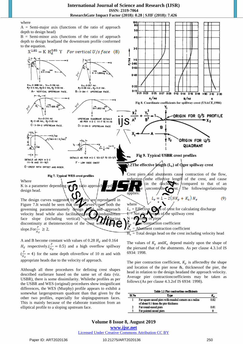
where
A = Semi-major axis (functions of the ratio of approach
depth to design head)
B = Semi-minor axis (functions of the ratio of approach
depth to design head)and the downstream profile conformed
to the equation.
Where
K is a parameter depending on the ratio approach depth and
design head.
The design curves suggested by Murphy are reproduced in
Figure 7.It would be seen that these curves cover both the
governing parametersnamely design head and approach
velocity head while also facilitating any desiredupstream
face slope (including vertical) without introducing
discontinuity at theintersection of the crest with upstream
slope.For𝑃
𝐻𝑑 ≥ 2,
A and B become constant with values of 0.28 𝐻𝑑 and 0.164
𝐻𝑑 respectively.(𝑃
𝐻𝑑= 0.5) and a high overflow spillway
(𝑃
𝐻𝑑= 4) for the same depth ofoverflow of 10 m and with
appropriate heads due to the velocity of approach.
Although all three procedures for defining crest shapes
described earlierare based on the same set of data (viz.
USBR), there is some dissimilarity. Whilethe profiles as per
the USBR and WES (original) procedures show insignificant
differences, the WES (Murphy) profile appears to exhibit a
somewhat largerupstream quadrant than that given by the
other two profiles, especially for slopingupstream faces.
This is mainly because of the elaborate transition from an
elliptical profile to a sloping upstream face.
2.2The effective length (𝐋𝐞) of Ogee spillway crest
Crest piers and abutments cause contraction of the flow,
reduction inthe effective length of the crest, and cause
reduction in the dischargeas compared to that of an
otherwise uncontrolled crest. The followingrelationship
applies:
where
𝐿𝑒 = Effective length of crest for calculating discharge
L = Net clear length of the spillway crest
N = Number of piers
Kp = Pier contraction coefficient
𝐾𝑎 = Abutment contraction coefficient
He = Total design head on the crest including velocity head
The values of 𝐾𝑝 and𝐾𝑎 depend mainly upon the shape of
the piersand that of the abutments. As per clause 4.3.1of IS
6934: 1998.
The pier contraction coefficient, 𝐾𝑝 is affectedby the shape
and location of the pier nose &, thicknessof the pier, the
head in relation to the design headand the approach velocity.
Average pier contractioncoefficients may be taken as
follows:(As per clause 4.3.2of IS 6934: 1998).
Paper ID: ART2020136 10.21275/ART2020136 250
International Journal of Science and Research (IJSR) ISSN: 2319-7064
ResearchGate Impact Factor (2018): 0.28 | SJIF (2018): 7.426
Volume 8 Issue 8, August 2019
www.ijsr.net Licensed Under Creative Commons Attribution CC BY
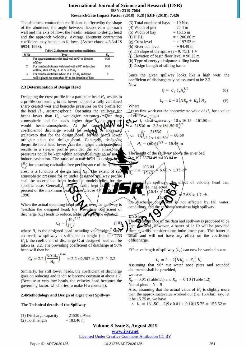
The abutment contraction coefficient is affectedby the shape
of the abutment, the angle between theupstream approach
wall and the axis of flow, the headin relation to design head
and the approach velocity. Average abutment contraction
coefficient may betaken as follows: (As per clause 4.3.3of IS
6934: 1998).
2.3 Determination of Design Head
Designing the crest profile for a particular head 𝐻𝑑 ,results in
a profile conforming to the lower nappeof a fully ventilated
sharp crested weir and hencethe pressures on the profile for
the head 𝐻𝑑 , areatmospheric. Operating the spillway for
heads lower than 𝐻𝑑 , wouldgive pressures higher than
atmospheric and for heads higher than 𝐻𝑑 ,the pressure
would besub-atmospheric. At the same time the
coefficientof discharge would be reduced or increased
(relativeto that for the design head) for the heads lower
orhigher than the design head. Generally, designing
theprofile for a head lower than the highest anticipatedhead
results in a steeper profile provided the sub atmospheric
pressures could be kept within acceptablelimits so as not to
induce cavitation. The ratio of actual head to design head
(𝐻
𝐻𝑑) for ensuring cavitation free performance of the spillway
crest is a function of design head 𝐻𝑑 . The extent of sub
atmospheric pressure for an under designed spillway profile
shall be ascertained from hydraulic modelstudies for the
specific case. Generally, design headis kept as 80 to 90
percent of the maximum head.As per clause 4.4 of IS 6934:
1998.
When the actual operating head passing over the spillway is
'lessthan the designed head, the prevailing coefficient of
discharge (𝐶𝑑 ) tends to reduce, andis given by the equation
where 𝐻𝑒 is the designed head including velocityhead.Since
an overflow spillway is sufficient in height (i.e. h.> 1.33
𝐻𝑑 ); the coefficient of discharge C at designed head can be
taken as. 2.2. The prevailing coefficient of discharge at 90%
head will then be
Similarly, for still lower heads, the coefficient of discharge
goes on reducing and tend~ to become constant at about 1.7.
(Because at very low heads, the velocity head becomes the
governing factor, which tries to make H a constant).
2.4Methodology and Design of Ogee crest Spillway
The Technical details of the Spillway
(1) Discharge capacity = 21530 m³/sec
(2) Total length = 183.46 m
(3) Total number of bays = 10 Nos
(4) Width of pier = 2.44 m
(5) Width of bay = 16.15 m
(f) H.F.L = + 206.80 m
(g) Crest level = + 197.53 m
(h) River bed level = + 94.49 m
(i) D/s slope of the spillway= 0. 75H: 1 V
(j) Elevation of basin floor level = 90.22 m
(k) Type of energy dissipator stilling basin
(l) Design Length of stilling basin
Since the given spillway looks like a high weir, the
coefficient of dischargemay be assumed to be 2.2.
Now
Where
Let us first work out the approximate value of 𝐻𝑒 for a value
of effective length
𝐿𝑒 ≈ 𝐿= clear waterway= 10 x 16.15 = 161.50 m
or 𝐻𝑒 = (60.6)2/3 = 15.43 m
The height of the spillway above the river bed
P = 197.53-94.49 = 103.04 m
Since P
He
, 𝑖. 𝑒.103.04
15.43= 6.68 > 1.33 𝑜𝑘
It is a high spillway, the effect of velocity head can,
therefore, be. neglected. 𝐻𝑒 + 𝑃
𝐻𝑒
= (15.43 + 103.04)
15.43= 7.68 > 1.7 𝑜𝑘
the discharge coefficient is not affected by fail water.
conditions, and the spillway remainsa high spillway.
U/s Slope
The upstream face of the dam and spillway is proposed to be
kept ·vertical. However, a batter of 1: 10 will be provided
from stability considerations inthe lower part. This batter is
small and will not have any effect on the coefficient
ofdischarge.
Effective length of spillway (𝐿𝑒) can now be worked out as
𝐿𝑒 = 𝐿 − 2 𝑁𝐾𝑝 + 𝐾𝑎 𝐻𝑒
Assuming that 90° cut water nose piers and rounded
abutments shall be provided,
we have
𝐾𝑝 = 0.01 (Table1.1) and 𝐾𝑎 = 0.10 (Table 1.2)
No. of piers = N = 9
Also, assuming that the actual value of 𝐻𝑒 is slightly more
than the approximatevalue worked out (i.e. 15.43m), say, let
it be 15.75 m, we have
∴ 𝐿𝑒 = 161.50 − 2 9𝑥 0.01 + 0.10 15.75 = 155.52 𝑚
Paper ID: ART2020136 10.21275/ART2020136 251

International Journal of Science and Research (IJSR) ISSN: 2319-7064
ResearchGate Impact Factor (2018): 0.28 | SJIF (2018): 7.426
Volume 8 Issue 8, August 2019
www.ijsr.net Licensed Under Creative Commons Attribution CC BY
Hence
or
𝐻𝑒 = (62.93)3/2 = 𝟏𝟓. 𝟖𝟐 𝐦 ≅ 𝟏𝟓. 𝟕𝟓 𝐦 (𝑎𝑠𝑠𝑢𝑚𝑒𝑑)
Hence, the assumed 𝐻𝑒 for calculating. 𝐿𝑒 is all right. The
crest profile will bedesigned for 𝐻𝑑= 15.82m (neglecting
velocity head).
Note: The velocity head 𝑯𝒂 can also be calculated as
follows:
Velocity of approach
= (1.02)2
2𝑥 9.81= 0.053 𝑚
This is very small and was, therefore, neglected.
Downstream profile: The W.E.S. D/s profile for a vertical
U/s face is given byequation (3) as:
Before we determine the various coordinates of the D/s
profile, we shall firstdetermine the tangent point.
The D/s slope of the dam is given to be 0. 7.5H: 1 V.
Hence 𝑑𝑦
𝑑𝑥
=1
7.5
Differentiating the equation (10) of the D/s profile w.r. to x,
we get
The coordinates from x = 0 to x = 24.32 mare worked out in
Table 1.3.
The U/s profile: The U/s profile may be designed as per
equation (4), as:
This curve should go upto X = - 0.27 𝐻𝑑
or
X = - 0.27 x 15.82 = - 4.27 m.
Various values of x such as, X=0.5 to X= - 4.27 are
substituted in equation (11) arid corresponding values of Y
are workedout, as given below in Table 1.4.
Paper ID: ART2020136 10.21275/ART2020136 252
International Journal of Science and Research (IJSR) ISSN: 2319-7064
ResearchGate Impact Factor (2018): 0.28 | SJIF (2018): 7.426
Volume 8 Issue 8, August 2019
www.ijsr.net Licensed Under Creative Commons Attribution CC BY
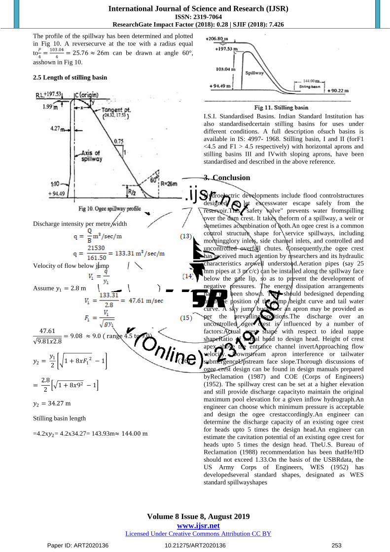
The profile of the spillway has been determined and plotted
in Fig 10. A reversecurve at the toe with a radius equal
to𝑃
4=
103.04
4= 25.76 ≈ 26m can be drawn at angle 60°,
asshown in Fig 10.
2.5 Length of stilling basin
Discharge intensity per metre width
Velocity of flow below jump
Assume 𝑦1 = 2.8 m
47.61
9.81𝑥2.8= 9.08 ≈ 9.0 ( range 4.5 to 9.0)
𝑦2 = 𝑦1
2 1 + 8𝑥𝐹1
2 − 1 (16)
= 2.8
2 1 + 8𝑥92 − 1
𝑦2 = 34.27 m
Stilling basin length
=4.2x𝑦2= 4.2x34.27= 143.93m≈ 144.00 m
I.S.I. Standardised Basins. Indian Standard Institution has
also standardisedcertain stilling basins for uses under
different conditions. A full description ofsuch basins is
available in IS: 4997- 1968. Stilling basin, I and II (forF1
<4.5 and F1 > 4.5 respectively) with horizontal aprons and
stilling basins III and IVwith sloping aprons, have been
standardised and described in the above reference.
3. Conclusion
Hydroelectric developments include flood controlstructures
designed to let excesswater escape safely from the
reservoir.This "safety valve" prevents water fromspilling
over the dam crest. It takes theform of a spillway, a weir or
sometimes acombination of both.An ogee crest is a common
control structure shape for service spillways, including
morningglory inlets, side channel inlets, and controlled and
uncontrolled overfall chutes. Consequently,the ogee crest
has received much attention by researchers and its hydraulic
characteristics arewell understood.Aeration pipes (say 25
mm pipes at 3 m c/c) can be installed along the spillway face
below the gate lip, so as to prevent the development of
negative pressures. The energy dissipation arrangements
have not been shown. They should bedesigned depending
upon the position of the jump height curve and tail water
curve. A sky jump bucket or an apron may be provided as
per the prevailingconditions.The discharge over an
uncontrolled ogee crest is influenced by a number of
factors:Actual crest shape with respect to ideal nappe
shapeRatio of actual head to design head. Height of crest
apex above the entrance channel invertApproaching flow
velocity. Downstream apron interference or tailwater
submergenceUpstream face slope.Thorough discussions of
ogee crest design can be found in design manuals prepared
byReclamation (1987) and COE (Corps of Engineers)
(1952). The spillway crest can be set at a higher elevation
and still provide discharge capacityto maintain the original
maximum pool elevation for a given inflow hydrograph.An
engineer can choose which minimum pressure is acceptable
and design the ogee crestaccordingly.An engineer can
determine the discharge capacity of an existing ogee crest
for heads upto 5 times the design head.An engineer can
estimate the cavitation potential of an existing ogee crest for
heads upto 5 times the design head. TheU.S. Bureau of
Reclamation (1988) recommendation has been thatHe/HD
should not exceed 1.33.On the basis of the USBRdata, the
US Army Corps of Engineers, WES (1952) has
developedseveral standard shapes, designated as WES
standard spillwayshapes
Paper ID: ART2020136 10.21275/ART2020136 253

International Journal of Science and Research (IJSR) ISSN: 2319-7064
ResearchGate Impact Factor (2018): 0.28 | SJIF (2018): 7.426
Volume 8 Issue 8, August 2019
www.ijsr.net Licensed Under Creative Commons Attribution CC BY
References
[1] IS:6934 -1998 “Recommendations for Hydraulic
Design of High Ogee overflowSpillways” by Bureau of
Indian Standards, New Delhi
[2] IS:5186 - 1994 “Criteria for Design of Chute and side
Channel Spillways” by Bureauof Indian Standards, New
Delhi
[3] IS:6966 part 1) - 1989 “Criteria for Hydraulic Design of
Barrages and Weirs” by Bureau ofIndian Standards,
New Delhi
[4] IS 11130 (1984): “Criteria for Structural Design of
Barragesand Weirs”by Bureau ofIndian Standards, New
Delhi
[5] Design of Small Dams, United States Bureau of
Reclamation. USBR, USA, 1960.
[6] “Engineering for Dams” Vol. 1, Wiley Eastern Pvt. Ltd.
New Delhi byCreager, Justin & Hinds.
[7] Khatsuria, R. M., Hydraulics of Spillways and Energy
Dissipators, Novak, A.I.B. Moffat, C. Nalluri, R.
Narayanan, Hydraulic Structures, 4th Ed. CRC Press
[8] Santosh Kumar. Garg., Irrigation Engineering and
Hydraulic Structures, Khanna Publishers, New Delhi
[9] Mays, L. W., Hydraulic design handbook (CHAPTER
18), Mcgraw hills
[10] Design of small dams. (1977). U.S. Bureau of
Reclamation, U.S. GovernmentPrinting Office,
Washington, D.C.
[11] Murphy, T. E. Spillway crest design - Misc Paper No.
H-73–5, U.S. Army EngineerWaterways Experiment
Station, 1973.
[12] US Army Engineer – Waterways Experiment Station –
Hydraulic Design Criteria– 1952 and subsequent
editions.
[13] United States Bureau of Reclamation (USBR) – Design
of small dams – 1960 andsubsequent editions.
Author Profile
Er Venkata Raju Badanapuri, Executive
Engineer,Water Resources Department, Government
of Andhra Pradesh, India. His educational
Qualifications includes Institute of Engineers India,
C.E (India), F.I.E. He didPost-Graduation in M. Tech
(Structural Engineering), J.N.T University, Hyderabad. He did
B.E.(Civil), Andhra University, Vishakhapatnam. He has following
Journal Publications in hisname: 1) “Indian Scenario of Water
Resources - An Overview, IntegratedWater Management and
Major Issues related to Indian Waters " inISSN:2321-7758, Vol.6.,
Issue.5, 2018 Sept-Oct., PP 64-70,International Journal of
Engineering Research by VENKATA RAJUBADANAPURI. 2)
“An Overview of Integrated theory of Irrigation Efficiency
andUniformity and Crop Water Use Efficiency Indian Waters "
inISSN:2321-7758, Vol.6., Issue.6, 2018 Nov-Dec., PP 11-
26,International Journal of Engineering Research by VENKATA
RAJUBADANAPURI 3) “Water Resources Scenario in India: Its
Requirement,Water Degradation and Pollution, Water Resources
Management”ine-ISSN:2348-6848, Volume 05 Issue 23December
2018, PP 672-696, International Journal of Research byVENKATA
RAJU BADANAPURI. 4) “Seismic Forces and Stability Analysis
of Gravity Dam” in ISSN: 2319-7064, Volume 08 Issue 06 June
2019, PP 2021- 2030, International Journal of Science and
Research (IJSR)by VENKATA RAJU ADANAPURI
Paper ID: ART2020136 10.21275/ART2020136 254