design procedure for a novel gravity rocking moment frame
TRANSCRIPT

Proceedings of the Tenth Pacific Conference on Earthquake Engineering
Building an Earthquake-Resilient Pacific
6-8 November 2015, Sydney, Australia
Design procedure for a novel gravity rocking moment frame system
M. Jamil, P. Quenneville & C. Clifton
The University of Auckland, Auckland, New Zealand.
ABSTRACT: A new hybrid steel/timber gravity moment frame system has been
developed and successfully tested on a shake table. The seismic design procedure differs
from conventional moment frames in several ways, principal of which is that the vertical
loading of the floors provides the principal seismic resistance as well as generating the
inertial forces. The joint and all members remain elastic and non-linear behaviour is
limited to the dynamic corbel system which acts as a semi-rigid joint. Guidelines are
provided for estimating joint moment strength, joint component design actions, beam and
column actions and bending moment patterns. Information is given on detailing of joint
components required for the joint to function as intended without displacement
compatibility issues.
1 INTRODUCTION
A novel moment frame system that utilises gravity to generate lateral resistance and self-centring has
been developed. In-line with current seismic performance-based targets, the objective of the system is
not only to provide life-safety but also to minimise structural damage during a strong earthquake. A
preliminary design procedure has been developed using a Force-Based Design method which is
prevalent in most current design standards. Nonetheless, limiting drift is essential for damage control
and drift checks are done before strength design of members, especially given that timber moment
frame member sizes tend to be stiffness governed rather than strength governed. The unique
mechanism for developing the seismic resistance means that bending moment demand in the beams
and columns are particular to this system. The intent of this paper is not to present a comprehensive
design procedure, but to highlight key differences when compared to conventional lateral load
resisting structural systems and give some details of the development work undertaken.
2 GRAVITY ROCKING MOMENT FRAME SYSTEM
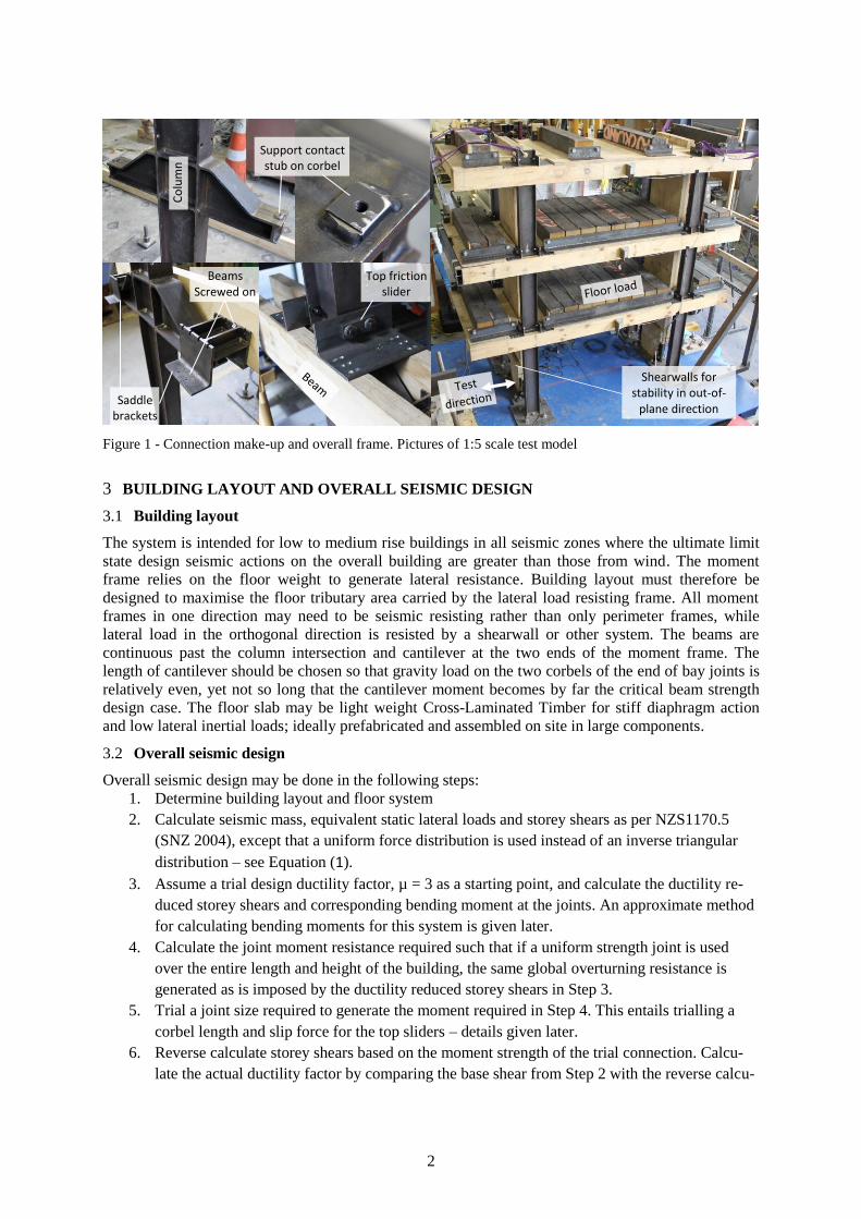
2.1 The concept
The key element of this system is a rocking corbel system through which the columns engage the floor
system. This is shown in Figure 1; taken from a1:5 scale model of the new system which was tested
with quasi-static lateral loading and also on a shake table. Steel I-sections were used for the heavily
loaded columns for strength and stiffness, and LVL was used for the beams which are relatively
lightly loaded. Cantilevered steel corbels welded to the column support the twin-section beams in
bearing through a ‘saddle’ bracket. As the column leans over in a strong earthquake, one corbel picks
up its tributary floor load while the other corbel disengages. This mechanism generates moment
resistance and self-centring. Asymmetric friction sliders at the top of the connection restrain the beams
from horizontal translation relative to the column but allow vertical translation. These friction sliders
add resistance to floor uplift, and hence add moment resistance to the joint while also adding energy
dissipation.
2.2 1:5 scale tests
Concept development, a numerical model, component tests, quasi-static cyclic tests and shake table
tests of a 1:5 scale model loaded up to 4.5% drift have been completed. A suite of 7 earthquakes
scaled to SLS, ULS and MCE level for Wellington, New Zealand and soil type D was used. Scaling
similitude rules were followed using an acceleration and material stiffness scale factor of one and
resulting mass scale factor of 25 (prototype / model). The model building remained within target drift
limits, self-centred fully and suffered negligible damage. More detail may be found in (Jamil,
Quenneville et al. 2014).
Paper Number 187
2
Figure 1 - Connection make-up and overall frame. Pictures of 1:5 scale test model
3 BUILDING LAYOUT AND OVERALL SEISMIC DESIGN
3.1 Building layout
The system is intended for low to medium rise buildings in all seismic zones where the ultimate limit
state design seismic actions on the overall building are greater than those from wind. The moment
frame relies on the floor weight to generate lateral resistance. Building layout must therefore be
designed to maximise the floor tributary area carried by the lateral load resisting frame. All moment
frames in one direction may need to be seismic resisting rather than only perimeter frames, while
lateral load in the orthogonal direction is resisted by a shearwall or other system. The beams are
continuous past the column intersection and cantilever at the two ends of the moment frame. The
length of cantilever should be chosen so that gravity load on the two corbels of the end of bay joints is
relatively even, yet not so long that the cantilever moment becomes by far the critical beam strength
design case. The floor slab may be light weight Cross-Laminated Timber for stiff diaphragm action
and low lateral inertial loads; ideally prefabricated and assembled on site in large components.
3.2 Overall seismic design
Overall seismic design may be done in the following steps:
1. Determine building layout and floor system
2. Calculate seismic mass, equivalent static lateral loads and storey shears as per NZS1170.5
(SNZ 2004), except that a uniform force distribution is used instead of an inverse triangular
distribution – see Equation (1).
3. Assume a trial design ductility factor, µ = 3 as a starting point, and calculate the ductility re-
duced storey shears and corresponding bending moment at the joints. An approximate method
for calculating bending moments for this system is given later.
4. Calculate the joint moment resistance required such that if a uniform strength joint is used
over the entire length and height of the building, the same global overturning resistance is
generated as is imposed by the ductility reduced storey shears in Step 3.
5. Trial a joint size required to generate the moment required in Step 4. This entails trialling a
corbel length and slip force for the top sliders – details given later.
6. Reverse calculate storey shears based on the moment strength of the trial connection. Calcu-
late the actual ductility factor by comparing the base shear from Step 2 with the reverse calcu-
Shearwalls for stability in out-of-
plane direction Saddle
brackets
Beams Screwed on
Co
lum
n
Support contact stub on corbel
Top friction slider

3
lated base shear. Revise the ductility reduced base shear in Step 3 and iterate from Step 2 to
Step 6 if the discrepancy between design and actual base shear is large.
7. Check frame drift at this stage, using the actual structural ductility factor and allowing for P-
Delta effects. Re-size members to achieve the required stiffness.
8. Size members to resist over-strength actions from the connections. An overall joint over-
strength factor, φo, joint, of 1.3 for corbel, beam and column design is tentatively suggested.
Storey seismic force distribution up the height of the building with this uniform strength system is
better estimated as a rectangular pattern rather than an inverse triangular pattern, as given by
𝐹𝑖 = 𝐹𝑡 + 0.92𝑉𝑊𝑖
∑ 𝑊𝑖𝑛𝑖=1
(1)
Seismic inertia forces are proportional to building mass and lateral resistance is derived mainly from
floor weight (but also from resistance of the top friction sliders). This means that if a seismic mass
higher than that assumed in the design is present at the time of the earthquake, the members will have
higher than design actions. It is suggested that the seismic weight at each level be calculated as
𝑊𝑖 = 𝐺𝑖 + ∑ ψ𝑎 ψ𝑐 𝑄𝑖 (2)
where ψc = 0.7 is tentatively suggested instead of a ψE of 0.3 considering the probably of a design
level earthquake coinciding with a high floor imposed load; and ψa = 0.5, except for very small
buildings (SNZ 2002). The overall seismic weight is from permanent and imposed loads. Permanent
load from a heavy floor slab will reduce the uncertainty in seismic weight – and thus reduce
uncertainty in joint opening moment and member actions – but is not advantageous over a light floor
system such as CLT which will have lower seismic weight but high in-plane strength and stiffness.
Lateral loads from the wind case are not dependent on the building weight, but the lateral strength is.
In the case of a lightly loaded building coinciding with a strong wind event, the system should be
designed such that the joint does not open and the behaviour remains linear. Alternatively, joint
opening (and corresponding higher drift) may be allowed for the ULS or higher wind case given that
the system is fully self-centring. It is suggested that earthquake design be carried out first and then the
light floor load wind case be checked.
The connection can be designed to accommodate very large rotation and hence building drift. The
slotted holes in the bolted friction slider may be made so that the bolts reach the end of the slot at a
drift of 4%. Beyond this extreme drift which would only be exceeded in a stronger than MCE
earthquake, the joint would lock-up and behave like a conventional timber fastener connection.
Damage would occur in such an extreme event associated with strength increase. Capacity design
should be used to define a strength hierarchy so the screws in the top slider-to-beam connection yield
first, and then the screws in the saddle bracket and then the corbel.
4 JOINT STRENGTH AND MEMBER ACTIONS
4.1 Gravity load cases
The beam moment and shear from applied loading is relatively low because it is supported at two
points on either side of the column by the corbels, as shown in Figure 2. The bending moment for the
inner beams may be estimated as a fixed ended beam spanning between opposite facing corbels. The
moment in the beams in the last bay depends on the back span moment from the cantilever.
Figure 2 - Bending moment from gravity only load

4
The two corbels at a joint share the vertical load. This sharing is near equal for inner connections but
depends on the inner-span to cantilever length for a connection at the end of a bay. An estimate of the
load sharing may be made by distributing the load proportionally to the tributary floor area carried by
each corbel. Out-of-balance moment from the corbels is transferred into the columns and may be
distributed into two ends of the column proportionally to the I/L of the column above and below the
corbel as per clause 4.3.4 of NZS3404 (SNZ 1997). It is likely that in a high seismic zone, the
earthquake load combination will govern the corbel strength requirement because one corbel carries
the entire tributary load on the joint and the corbel on the other face of the column disengages.
4.2 Earthquake - Joint strength
The joint is semi-rigid, i.e. it remains rigid up to the design ULS level and ‘opens’ beyond that. Figure
3 shows forces acting inside the joint to generate moment resistance. Tributary gravity load supported
by the engaged corbel acts at an eccentricity to the column centreline, G. The friction slider restrains
the beam to the column at the top of the joint but allows it to move vertically. Therefore sliding must
occur at the corbel support to saddle bracket interface for the joint to rotate. The friction force
mobilised at this interface acts through the lever arm F. The friction forces in the two top brackets act
through lever arms B1 and B2 to the support point and add to the moment resistance – this is
independent of the floor load. A coefficient of friction of 0.40 is suggested for the top slider and beam
support contact, based on (Khoo, Clifton et al. 2015). An over-estimate of the coefficient of friction
would over-estimate joint moment capacity and hence overall frame strength and under-estimate self-
centring tendency.
Figure 3 – Left: Mechanics of new gravity rocking joint. Right: Moment-Rotation of joint
The corbel length and target slip force of the top slider may be determined using the following steps:
1. Select target slip force for two top sliders, Fslider,slip, such that the minimum weight carried by
the joint is greater. This is necessary for the floor to settle back down after uplift.
0.9G𝑗𝑜𝑖𝑛𝑡 > 2 × F𝑠𝑙𝑖𝑑𝑒𝑟,𝑠𝑙𝑖𝑝 (3)
2. Given Fslider,slip from Step 1, calculate the corbel length needed to achieve the required joint
moment strength for an inner column from Step 4 of the overall seismic design procedure. The
method for calculating joint strength is given below.
3. For effective dynamic self-centring, a restoring moment (from gravity), Mrestor, to resisting
moment (from friction) Mresist, ratio of 1.2 or greater is tentatively suggested based on the
over-strength generated by the friction sliders.
𝑀𝑟𝑒𝑠𝑡𝑜𝑟 ≥ 1.2 × 𝑀𝑟𝑒𝑠𝑖𝑠𝑡 (4)
𝑀𝑟𝑒𝑠𝑡𝑜𝑟 = 𝐺𝑟𝑎𝑣𝑖𝑡𝑦 × 𝐺 (5)
𝑀𝑟𝑒𝑠𝑖𝑠𝑡 = 𝐹𝑟𝑖𝑐𝐺 × 𝐹 + 𝐹𝑟𝑖𝑐1 × 𝐵1 + 𝐹𝑟𝑖𝑐2 × 𝐵2 (6)
Mo
men
t
Rotation
Fric
tio
n
Gra
vity

5
4. Calculate joint actions for the end column with compression from beam shear. This is likely to
be the critical joint for strength design of joint components.
Joint internal actions may now be determined. In the following equations, internal actions are
designated A, M or V for axial, moment and shear actions respectively and forces acting on
components are designated F. Frame bending moment and dimensions needed for moment calculation
are shown in Figure 4.
Figure 4 - Bending moment after joint uplift (sway to right) overlaid on drawing of 1:5 scale test building
The total vertical load supported by the corbel, Fcor, vertical, is given by
Fcor,vert = [G + ψ𝑎ψ𝑐Q]𝑗𝑡 + Acol,beam shear + 2 × Fslider,slip (7)
where ψc = 0.7 as suggested for the seismic design case; and Acol, beam shear = the vertical load imposed
onto the corbel of an end column by action of out-of-balance beam shear as calculated using Equation
(9); and ψ𝑎 is for the tributary area of floor supported by the joist. Note that the end column with
compression from beam shear also supports more tributary beam length than the end column with
tension from beam shear. The tributary beam length over support 2 in Figure 4 is the entire cantilever
on the right and the beam half-way to support 1 on the left.
Fcor, vert may be used to calculate the corbel moment, Mcor, taken at the face of the column and the
corbel moment feeding into the column, Mcor, col, taken at the centreline of the column.
The friction slip force at the corbel support point, Fcor, slip is
Fcor,slip = μ𝑠𝑙𝑖𝑝 × 𝐹𝑐𝑜𝑟,𝑣𝑒𝑟𝑡 (8)
4.3 Earthquake - Member actions
Axial load in end columns due to out-of-balance shear from beams is given by
𝐴𝑐𝑜𝑙,𝑏𝑒𝑎𝑚 𝑠ℎ𝑒𝑎𝑟 = (𝑀𝑏𝑒𝑎𝑚,𝑠𝑢𝑝𝑝𝑜𝑟𝑡 2 − 𝑀𝑏𝑒𝑎𝑚,𝑠𝑢𝑝𝑝𝑜𝑟𝑡 1) / 𝑠𝑝𝑎𝑛 (9)
Mbeam, support 1 and Mbeam, support 2 may be calculated using Equation 11. The span here is between two
supporting corbels at support 1 and support 2 and is the column centre to centre distance, which is
different to the tributary length of beam supported by the joint.
The moment generated in the beam by this friction force is
𝑀𝑏𝑒𝑎𝑚,𝑐𝑜𝑟 𝑠𝑙𝑖𝑝 = 𝐹𝑐𝑜𝑟,𝑠𝑙𝑖𝑝 × 𝐿𝑠𝑢𝑝𝑝/𝑏𝑒𝑎𝑚 𝐶𝐿 (10)
where Lsupp/beam CL = the lever arm taken vertically from the corbel sliding interface to the beam
centreline. Axial force in the horizontal leg of the top slider steel angle may be conservatively
assumed to be equal to the Fcor, slip. This assumes it is all resisted by the angle slider on the opposite
side of the column.
Bending moment in the beam is from gravity loads in simply supported conditions, contribution from
Fcor, slip and horizontal and vertical actions in the top sliders. Hogging moment in the beam over the
Mbeam, support 2
Mbeam, support 1
Lslider/supp vert
L
supp/beam CL
LbeamCL/slider
Lsupp/slider, a
Lsupp/slider, b
Lcor depth
Mbeam, support 2

6
support point of the higher compression end column is likely to govern beam strength design unless
the end of bay cantilever is very small.
𝑀𝑏𝑒𝑎𝑚,𝑠𝑢𝑝𝑝 = 𝑀𝑏𝑒𝑎𝑚,𝑔𝑟𝑎𝑣 + 𝐹𝑐𝑜𝑟,𝑠𝑙𝑖𝑝 × 𝐿𝑠𝑢𝑝𝑝/𝑏𝑒𝑎𝑚 𝐶𝐿 + 𝐴𝑏𝑟𝑎𝑐,𝑎 × 𝐿𝑏𝑒𝑎𝑚𝐶𝐿/𝑠𝑙𝑖𝑑𝑒𝑟 +
𝐴𝑏𝑟𝑎𝑐,𝑏 × 𝐿𝑏𝑒𝑎𝑚𝐶𝐿/𝑠𝑙𝑖𝑑𝑒𝑟 + 𝐹𝑠𝑙𝑖𝑑𝑒𝑟 𝑠𝑙𝑖𝑝,𝑎 × 𝐿𝑠𝑢𝑝𝑝/𝑠𝑙𝑖𝑑𝑒𝑟,𝑎 +
𝐹𝑠𝑙𝑖𝑑𝑒𝑟 𝑠𝑙𝑖𝑝,𝑏 × 𝐿𝑠𝑢𝑝𝑝/𝑠𝑙𝑖𝑑𝑒𝑟,𝑏 (11)
where Abrac, a and Abrac, b = the axial forces in the lower legs of the two top sliders; and Fslider slip, a and
Fslider slip, b = slip force in the two friction sliders. An over-strength factor, φo, slip, of 1.4 should be
applied to Fslider slip to account for uncertainty in slip force in the friction sliders. This φo affects the
actions on the joint, beam and column. It is not applied for overall lateral resistance of the frame but is
for sizing the top slider, saddle brackets and screws. The overall joint overstrength, φo, joint, of 1.3
suggested earlier is for sizing of the corbel, column and beam. These overstrength factors have not
been included in the equations here but need to be applied when designing the relevant component.
After taking overstrength factors into account, design should be to principles of NZS3404 (SNZ 1997)
and NZS3603 (SNZ 1993) or other timber structural design standard, e.g. (CEN 2004) or (CSA 2009).
At present there is simultaneous loading demand on the corbel from vertical earthquake loading as it is
highly unlikely that vertical loading will combine with overstrength actions from horizontal loading.
Note that Fcor, vert depends on Acol, beam shear which depends on Mbeam, supp which depends on Fcor, slip which
in turn depends on Fcor, vert. This means that a few iterations may be required before the final joint
actions are found. Alternatively, if Lsupp/ beam CL is small, the moment from Lsupp/ beam CL may be assumed
insignificant for iteration.
Column axial force is an accumulation of Fcor, vert, Fslider slip and column self-weight over the height of
the building. The end column with compression from beam shear and increased tributary floor weight
is likely to be critical for strength design of the columns. Bending moment in the columns may be
estimated as below for each location:
𝑀𝑐𝑜𝑙,𝑏𝑒𝑙𝑜𝑤 𝑐𝑜𝑟𝑏𝑒𝑙 = 𝑀𝑐𝑜𝑟,𝑐𝑜𝑙 (12)
𝑀𝑐𝑜𝑙,𝑓𝑙𝑜𝑜𝑟 = 𝑀𝑐𝑜𝑙,𝑏𝑒𝑙𝑜𝑤 𝑐𝑜𝑟𝑏𝑒𝑙 + 𝑉𝑝𝑎𝑛𝑒𝑙 × 𝐿𝑐𝑜𝑟 𝑑𝑒𝑝𝑡ℎ (13)
where Vpanel = the shear in the column/corbel panel zone. Equation 12 may unconservatively estimate
the critical column moment just below the corbel so this must be checked in a FE model. Column
shear may be estimated by distributing storey shear between columns proportionally to Mcol, below corbel.
5 JOINT DETAILING AND DESIGN
Careful detailing is required to ensure the connection functions as intended. The following is not a
comprehensive list of design checks required, but highlights the key items that need considering.
The maximum moment demand on the corbel is similar to that in the column so it is usually
convenient to use the same steel section. The principal action is vertical load, but there is also friction
force applied axially and also potentially sideways during bidirectional movement. The corbel is
tapered as shown if Figure 1 to match the cantilever bending moments with smooth rounds to
minimise stress concentrations. A hard wearing steel stub is used as a contact point for reliable and
repeatable friction sliding performance. A small, roughly square stub is used because the full area is
not utilised regardless, especially when the corbel rotates relative to the saddle bracket. Furthermore, a
smaller stub means that the loading point on the stub does not shift out far from the centre of the
corbel web when the stub is loaded on an edge or corner. All four edges of the stub need to be rounded
to prevent the edges gouging into the underside of the mild steel saddle bracket. A threaded hole in the
middle of the stub may be used to line-up the middle of the saddle bracket with the contact stub for
ease of construction. Stiffener plates are provided under the contact stub to avoid twisting of the top
flange relative to the web when there is side-ways movement of the saddle bracket on the stub, as
shown in Figure 5. An advantage of using an I-section for the corbel is that it is torsionally flexible
which helps it withstand the deformation demand from out-of-plane action without inducing
significant additional stresses.

7
The saddle bracket needs to resist a concentrated load in the middle from the contact stub. Bearing
strength of the timber needs to be checked under the toes of the saddle legs. Fully threaded screws
may be used to reinforce the LVL beams for bearing if necessary. The toes are screwed into the
underside of the beam. Minimal strength is required from these screws because most of the sliding
shear is taken in friction between the timber and steel. There is some overturning moment due to the
contact stub friction force applied at an eccentricity to this bottom screw group. The side of the saddle
bracket is screwed into the timber beam from above and inside the beam at an angle. The saddle
bracket is located where the maximum hogging moment in the beam occurs and near the maximum
positive beam moment location so reduction in the cross-section area from screw holes needs to be
accounted for.
The top friction slider serves a number of purposes. The lower leg of the L shape steel angle axially
resists load from the column pushing or pulling at the bracket. The bracket resists uplift from the slider
friction force and also accommodates rotation of the column without bending the upper leg of the
angle because a compressible stack of Belleville washers is used in the bolted slider connection. A low
bolt strain is suggested so that the bolt never yields and behaviour is repeatable. An asymmetric slider
was used for the 1:5 scale model simply for ease of detailing. A symmetric slider, which has no-self
centring tendency, may be used since self-centring is primarily derived from gravity action on the
corbel. The slip force in one slider is given by
𝐹𝑠𝑙𝑖𝑑𝑒𝑟,𝑠𝑙𝑖𝑝 = 𝜇𝑠𝑙𝑖𝑝 × 𝑛𝑏𝑜𝑙𝑡 × 𝑛𝑠𝑢𝑟𝑓 × 𝐴𝑏𝑜𝑙𝑡 (14)
where µslip = the coefficient of friction, taken as 0.4; Abolt = the axial force in one bolt; nbolt = the
number of bolts; and nsurf = the number of sliding surface pairs. More detail about symmetric and
asymmetric sliders is available in the literature (Loo, Quenneville et al. 2014, Khoo, Clifton et al.
2015). Bending moment in the column just above the floor is relatively low so cross-section reduction
due to bolt holes is unlikely to be critical.
A tight fit tolerance is critical in all screw connections to minimise slack. A maximum load to design
strength ratio of 0.4 is recommended for all screw connections for high stiffness performance inside
the elastic range. Bolt holes for the friction slider should be 2 mm over-size to allow the bracket to
rotate about the beam axial direction during bidirectional movement of the frame. A gap is needed
between the corbel and the inside of the saddle bracket to accommodate out-of-plane rotation of the
joint as illustrated in Figure 5.
Figure 5 - Gap between corbel and inside of saddle bracket to accommodate bidirectional movement
6 OTHER CONSIDERATIONS AND LIMITATIONS
Conventional reinforced concrete moment frames and post-tensioned moment frames exhibit a beam
elongation effect when the beam-column joint opens. In the system presented here, the beam is
continuous so there is no beam elongation effect. Resistance is generated from floor uplift and this
uplift must be accommodated by cladding and non-structural partitions. Floor uplift is large only
between the ground and first suspended floor because the relative movement between other floors is
minimal for a strong column system dominated by the first mode of vibration. Relative uplift between
higher floors would be accommodated in standard detailing of cladding for fire and earthquake.
The coefficient of friction for the corbel contact stub may be higher than usual because of high stress
concentration. The yield stress of the steel is theoretically exceeded when the contact is only on an
edge or corner of the stub. However, from the 1:5 scale tests, sliding behaviour was repeatable and
there was minimal wear of the contact stub or underside of the saddle bracket.

8
To date 1:20 scale tests of an earlier version of the presented concept and 1:5 scale tests described
briefly here have been completed. A SAP2000 model has been made which has excellent correlation
with experimental results. Different building layouts, structural ductility ratios, more ground motions,
effect of vertical accelerations, significance of impact magnification at the corbel, cost optimisation
etc. remain to be fully investigated.
7 CONCLUSIONS
The new gravity rocking system presented can achieve low-damage, self-centring performance in a
strong earthquake. Design considerations unique to this system were discussed and it is concluded:
The moment frame system can achieve strength and stiffness in one direction of the building
for low to medium rise buildings in all seismic zones. Strength and stiffness are de-coupled
because a semi-rigid joint is used.
Floor weight is utilised to generate lateral strength and self-centring. This implies that as the
floor load increases for a given design, the joint components, beams and columns need to re-
sist higher actions. Overall drift would also be higher, but less so than for a conventional sys-
tem that does not derive strength from gravity.
The columns and beams have a unique bending moment pattern for the earthquake and gravity
cases respectively. Formulae to estimate these have been provided.
High energy dissipation from friction sliding can be achieved while having self-centring by
designing the restoring gravity forces to be greater than the resisting friction forces.
Some detailing is required to ensure that the intended mechanism is reliably achieved and
there are no displacement compatibility issues with bidirectional movement.
8 ACKNOWLEDGEMENTS
The authors would like to thank the New Zealand Ministry of Primary Industries for financially
supporting this project. The help of colleagues and lab technicians is also greatly appreciated.
9 REFERENCES
CEN 2004. Eurocode 5–Design of timber structures. EN 1995-1-1:2004 (E), Brussels, CEN, Comité Européen
de Normalisation (CEN), European Committee for Standardisation.
CSA 2009. Engineering design in wood. CSA O86-09, Toronto, Canadian Standards Association.
Jamil, M., Quenneville, P. and Clifton, G. C. 2014. Scaled shake table tests of a novel gravity rocking moment
frame system. NZSEE, Rotorua, New Zealand.
Khoo, H.-H., Clifton, C., MacRae, G., Zhou, H. and Ramhormozian, S. 2015. Proposed design models for the
asymmetric friction connection. Earthquake Engineering & Structural Dynamics 44(8): 1309-1324.
Loo, W. Y., Quenneville, P. and Chouw, N. 2014. A new type of symmetric slip-friction connector. Journal of
Constructional Steel Research 94(0): 11-22.
Newcombe, M., Pampanin, S., Buchanan, A. and Palermo, A. 2008. Seismic design of multistorey post-tensioned
timber buildings, Masters Thesis, University of Pavia, Pavia.
SNZ 1993. Timber Structures. NZS3603:1993, Wellington, Standards New Zealand.
SNZ 1997. Steel Structures Standard - Parts 1 and 2. NZS3404:Part 1:1997, Wellington, Standards New
Zealand.
SNZ 2002. Structural Design Actions - Part 1: Permanent, imposed and other actions. NZS1170.1:2002,
Standards New Zealand.
SNZ 2004. Structural Design Actions - Part 5: Earthquake actions - New Zealand. NZS1170.5:2004,
Wellington, Standards New Zealand.