design procedures for buildings incorporating hysteretic ... · pdf filetion detailing then...
TRANSCRIPT

Abstract
This paper outlines design studies and large-scale tests oftension/compression yielding braces (also called“unbonded braces”) in support of their first applications inthe United States. The core steel in these braces providesstable energy dissipation by yielding under reversed axialloading, while the surrounding concrete-filled steel tuberesists compression buckling. A slip surface or unbondinglayer separates the steel core from the surrounding tube.
The first section of the paper is focused on establishing theseismic demands on axial hysteretic elements in multi-story steel structures. The mathematical modelingemployed reproduces the force-displacement behavior ofunbonded braces, but the results can be generalized easilyto buildings with other types of hysteretic damping ele-ments.
The second portion of the paper summarizes a series oftests on large-scale unbonded braces. Three braces, havingyield forces of 270, 360, and 470 kips were subjected to acyclic loading pattern consistent with that used widely fortesting steel beam-column connections. Additional testsexplored the behavior of the braces under a near-fieldloading history, a displacement time history derived froma seismic analysis of an idealized 5-story building, and alow-cycle fatigue test.
The final portion of the paper describes design studies insupport of the first application of unbonded braces in theUnited States. Nonlinear pushover analyses of several dif-ferent braced frame designs corresponding to an eccentricbraced frame system, a concentric braced frame system,and an unbonded braced frame system are summarized.
Introduction
Engineers around the world are now considering the use ofseismic energy dissipation devices in structures large andsmall. The primary benefit of dampers — reliable absorp-tion of earthquake energy in elements separate from theprimary structural frame — is well established, but design-ers continue to struggle to identify appropriate designtechniques for the sizing and distribution of dampers inmulti-story buildings. Establishing straightforward designapproaches for hysteretic dampers is important for realiz-ing the advantages of these devices, particularly their lowcost, long-term reliability, and lack of dependence onmechanical components.
There has been considerable debate in the structural engi-neering community regarding the target performance levelfor structures with passive damping devices. Originally,dampers were envisioned as means of enhancing the per-formance of structures which already meet lateral force-resisting requirements, making supplemental dampingsuitable only for high-performance structures. Recently, itseems that for code-minimum performance levels there isa trend toward allowing reductions in the mandated lateralforce-resisting system in proportion to the benefits derivedfrom including dampers. Because structures with passivedamping systems can provide predictable and stablebehavior under seismic loading, it is appropriate thatdesigners be given the freedom to use these systems toattain a range of performance levels, from collapse-pre-vention to immediate occupancy.
This paper proposes a design procedure for hystereticdampers based on the equivalent static force method cur-rently prescribed for eccentric braced frames (EBFs) in theUniform Building Code. Conceptually, a structure using a
Design Procedures for Buildings IncorporatingHysteretic Damping Devices
Eric KoOve Arup and Partners
San Francisco, California
Isao KimuraNippon Steel Corporation
Tokyo, Japan
Peter Clark, Ian AikenSeismic Isolation Engineering, Inc.Oakland, California
Kazuhiko KasaiTokyo Institute of TechnologyYokohama, Japan
PROCEEDINGS, 68th ANNUAL CONVENTION, SANTA BARBARA, CALIFORNIASTRUCTURAL ENGINEERS ASSOCIATION OF CALIFORNIA, OCTOBER (1999)

lateral force-resisting system of hysteretic dampers basedon plastic deformation of steel should behave similar to aneccentric braced frame. In fact, a properly-designeddamped frame may prove to be more economical than anEBF, even when designed to code-minimum forces. Athree-story building previously used in the Phase 2 SACSteel Project to evaluate design procedures for steelmoment-resisting frames (SMRFs) is redesigned withunbonded braces, specially-detailed steel componentswhich can provide stable hysteretic behavior in both ten-sion and compression without buckling. A series of non-linear analyses is then undertaken to provide comparisonsof the performance of the unbonded braced frame (UBF)with the SMRF.
Results from a series of large-scale tests of unbondedbraces are next presented as evidence of the stable hyster-etic behavior that can be achieved. A number of cycles ofdisplacement at relatively large axial yield strains can besustained in the braces prior to failure, giving designersconfidence that a lateral force-resisting system incorporat-ing these elements will provide at least equivalent perfor-mance to and EBF.
As more designers begin to investigate the potential bene-fits of using unbonded braces, the first applications arebeing introduced. A brief summary of the design studies insupport of the implementation of unbonded braces in auniversity research laboratory closes the paper.
Background of Unbonded Braces
While the studies reported in this paper can be generalizedto any type of yielding steel damping element, the focushere is on a class of steel braces which dissipate energythrough stable tension-compression yield cycles. A varietyof these “unbonded braces” having various materials andgeometries have been proposed and studied extensivelyover the last 10-15 years. A summary of much of the earlydevelopment of unbonded braces which use a steel coreinside a concrete-filled steel tube is provided in Watanabe,et al., 1988, and since the 1995 Kobe Earthquake, theseelements have been used in numerous major structures inJapan (e.g., Reina, and Normile, 1997). In fact, the con-cept of “damage tolerant structures” — in which the theprimary structural system is designed to remain elasticwhile all energy dissipation occurs in specially-detailedcomponents of the lateral force-resisting system — isgaining broad acceptance in Japan (Wada, et al., 1997).According to records from the Building Center of Japanfor the year 1997, approximately two-thirds of all tallbuildings (greater than 60 meters) approved for design thatyear incorporate some form of passive damping system,and the majority of these use hysteretic dampers (BuildingCenter of Japan, 1997).
The basic principle in the construction of the most populartype of unbonded brace is to prevent Euler buckling of acentral steel core by encasing it over its length in a steeltube filled with concrete or mortar (Fig. 1). The term“unbonded brace” derives from the need to provide a slip
Figure 1. Schematic of Mechanism of Buckling-Resistant Unbonded Braces
“unbonding” material betweensteel core and mortar
yielding steel core
encasing
steel tube
tension
compression
Axial force-displacement behavior
mortar
unbondedbrace
typicalbuckling
brace
displacement

surface or unbonding layer between the steel core and thesurrounding concrete, so that axial loads are taken only bythe steel core. This materials and geometry in this sliplayer must be carefully designed and constructed to allowrelative movement between the steel element and the con-crete due to shearing and Poisson’s effect, while simulta-neously inhibiting local buckling of the steel as it yields incompression. The concrete and steel tube encasement pro-vides sufficient flexural strength and stiffness to preventglobal buckling of the brace, allowing the core to undergofully-reversed axial yield cycles without loss of stiffnessor strength. The concrete and steel tube also help to resistlocal buckling.
The stable hysteretic behavior of a properly detailedunbonded brace contrasts with the behavior of bracing ele-ments in typical concentrically-braced frames (CBFs).While a number of studies over the past two decades haveresulted in improved detailing requirements for brace ele-ments in CBFs and special CBFs, the anticipated behaviormode in compression remains global buckling of the braceand a consequent loss of strength and stiffness. Connec-tion detailing then becomes critical to the ability of thebrace to develop its full tension capacity under reversedloading, and consideration must also be given to the unbal-anced forces transferred to beams in frames with V-brac-ing or inverted V-bracing. While economical, suchsystems clearly have drawbacks in terms of seismic per-formance, and, as a consequence, equivalent static designforces for these systems tend to be quite large.
For structures designed in accordance with the life-safetyphilosophy of most building codes, this paper treats aframe having unbonded braces as essentially equivalent inseismic performance to an EBF. Such as system shouldthus require no additional design effort beyond an equiva-lent static analysis to determine the design brace forces.However, a useful result of the unbonded brace construc-tion is the ability to independently control strength, stiff-ness, and yield displacement or ductility by varying thecross-sectional area of the steel core, the yield strength ofthe steel, and the length of the core which is allowed toyield. This provides designers with the opportunity toaccurately tailor the force-displacement relationship oftheir lateral force-resisting elements according to theneeds of the application, making unbonded braces usefulin the context of design for performance levels other thanthose mandated by the code, such as for critical facilities.It is also noted that while the focus of this paper is on thedesign of new buildings, unbonded braces are clearlyapplicable for the upgrade of existing buildings such as
non-ductile reinforced concrete frames where additionalstiffness, strength, and energy dissipation may be benefi-cial.
Design Procedures for Braced Frames
The equivalent static lateral-force provisions in the 1994Uniform Building Code (UBC, 1994) are used as the basisfor the design of the unbonded braced frame (UBF) stud-ied in this paper. Before going into the details of thedesign, it is useful to briefly contrast the provisions forspecial concentrically-braced frames (SCBFs) and EBFs.For a given building site, the design forces implied by thecode requirements for SCBFs are typically 1.5 times thosefor EBFs, reflecting the increased likelihood for stiffnessand strength deterioration of buckling braces under cyclicloading (SCBFs have a force reduction factor, , of 9,
compared with the of 10 which is used for EBFs), as
well as the presumably shorter elastic period of a concen-trically braced frame ( is 0.020 for SCBFs, compared
with 0.030 for EBFs).
It is proposed here that frames designed to incorporateunbonded braces under equivalent static lateral-force pro-visions consistent with the UBC should use forces compat-ible with those used for EBFs, rather than those used forSCBFs. This is justified because the unbonded braces donot exhibit buckling and the stiffness and strength deterio-ration which inevitably accompanies buckling. Their sta-ble hysteretic behavior more closely resembles thebehavior of a shear link in an EBF. Further, the unbondedbraces do not need to be designed using the compressionstress-reduction factor, ( in the AISC provisions),
that takes into account the global buckling stability of thebrace element. This means that the unbonded braces willhave smaller steel cross-sectional areas, and therefore thestructure will have a longer elastic period, comparable tothat of an EBF.
Building Example Considered in this Study
The structure investigated in this analytical study is basedon a three-story special moment-resisting frame (SMRF)originally developed for a series of nonlinear time historyanalyses in Phase 2 of the FEMA/SAC Steel Project(SAC, 1999). The building is assumed to be located in LosAngeles (seismic zone 4) on UBC soil type S2, and wasdesigned to meet the 1994 UBC provisions. Using the
Rw
Rw
Ct
B φc

structural period given by Section 1628.2.2 (Method A) ofthe 1994 UBC, Table 1 presents the code-mandated designforces for each of three different types of structural sys-tems. It is clear that the SMRF has an advantage in termsof design base shear, but in fact, the frames are sized tomeet drift requirements and therefore have a much higheryield base shear. Figure 2 shows the geometry and mem-ber sizes of one of the moment-resisting frames in theNorth-South direction of the building that is used for thetime history analyses. For this structure, grade beams wereused at the foundation level to achieve full fixity of thecolumn bases.
Redesign of SAC SMRF Model Building Incorporating Unbonded Braces
Design Assumptions
This section describes the details of the three-story build-ing when redesigned according to the equivalent static lat-eral-force provisions for EBFs, but configured withunbonded braces. The goal is to use the same generalassumptions as were used for the SMRF and then comparethe configuration and performance of the UBF with that ofthe SMRF. A rational UBF design method to obtain opti-
mum performance has been developed previously (Kasaiet al. 1998). However, in the present paper we will illus-trate a method similar to those presented in the UBC forconventional steel structures. The method does not neces-sarily seek optimum performance. The advantages offeredby designing the UBF to the forces prescribed for the EBFas compared to those for the SCBF are significant, asdescribed above and shown in Table 1. Because driftdemands can be met in a braced system more easily, thereare further advantages over the moment frame, as there isno need to increase member sizes to control drift.
Since the 1994 UBC seismic load is based on workingstresses, it is increased by a factor of 1.5 times to estimatethe required yield lateral strength of the frame (per Div. Iand VIII of Chapter 22, UBC). The required yieldstrengths of the unbonded braces, , are obtained by
conservatively ignoring the moment resistance providedby the beams and columns, thereby allowing a staticallydeterminant truss analysis to be used for the design of thebraced bay (Fig. 3). The required cross sectional area ofthe yielding portion of the brace, , is then calculated
as
Py br,
A'br
Figure 2. Three-Story Special Moment-Resisting Frame from FEMA/SAC Project
Code DesignRequirements
Special Moment-Resisting Frame
Special Concentrically Braced Frame
Eccentric BracedFrame
Rw 12 9 10
Ct 0.035 0.020 0.030
Vbase 0.075W 0.145W 0.099W
Table 1: Design Parameters for Three Structural Systems
156"
TYP
. W24x68W24x68 W24x68
W30x116 W30x116 W30x116
W21x44
W21x44
W33x118 W33x118 W33x118 W21x44
360" TYP.
W14
x257
W14
x311
W14
x311
W14
x257
W14
x68

(Eq. 1)
where = yield strength of the brace steel material,
and=0.9 is the strength reduction factor.
For ultimate state design of elements around the link in anEBF, beams and columns typically are sized to support theaxial forces and moments generated by 1.25 times theyield strength of the link. (A method to explicitly considerthe effect of strain-hardening is presented in Kasai andGoyal, 1993). However, unlike EBF design, the momentsin the beams and colums of the UBF at its ultimate stateare difficult to estimate before knowing the element sizesand deformations (which depend on the story drifts),although the axial forces are easy to obtain. Our prelimi-nary design therefore employs some conservatism by con-sidering amplified axial forces in the braces due to strainhardening at their ultimate state to indirectly account forthe unknown seismic moment. The beams and columnsare then designed as beam-column elements to remainelastic even at the ultimate state. Note that for the UBF,there is no force imbalance at the connection of the bracesto the midpoint of the beam, because the tension and com-pression forces in the two braces in each bay are essen-tially equal.
Design Results
Based on the assumptions outlined above, the beams, col-umns, and cross-sectional areas of the yielding portion of
A′br
Py br,φFy br,----------------=
Fy br,
φ
the braces, , selected for the 3-story UBF are illus-
trated in Fig. 3. For the unbonded brace, Japanese steelSS400 ( = 2.4 tonf/cm2 = 34 ksi) is used, and for the
beams and columns A572 Grade 50 ( = 50ksi) is used.
Note that when compared with the SMRF (Fig. 2) usingsimilar steel ( is about 50 ksi), the UBF requires much
smaller steel sections. In fact, the total weight of the steel(including unbonded braces) in the UBF is only 0.51 timesthat of the SMRF. There are also substantially fewer rigidconnections used in the UBF, so it would be expected tobe less expensive than the SMRF. However, because all ofthe lateral force-resisting elements are concentrated in asingle braced bay, for this particular building on UBC soiltype S2, it is likely that pile foundations would be requiredto resist uplift under seismic input.
The length of the yielding portion of the braces,
=130 in., is obtained by subtracting the lengths of thesplice, gusset, beam, and column regions (at both ends ofthe brace) from the center-to-center length, = 238 in.
Since the yielding portion has a substantially smaller crosssectional area as compared with the end connections,
most of the elastic deformations take place therein, as wellas all of the inelastic deformations. Considering this, theelastic axial stiffness of each unbonded brace is approxi-mated by
A'br
Fy
Fy
Fy
L'br
Lbr
A'br
Figure 3. Three-Story Frame Redesigned with Unbonded Braces
156"
TYP
. W21x44 W21x44
W21x44 W14x53 W21x44
W21x44
W21x44
W21x44 W14x68 W21x44 W21x44
W14
x68
W14
x90
W14
x90
W14
x68
W14
x68
360" TYP.W14x38
A'br=5.4 sq. in.
A'br=8.8 sq. in.
A'br=10.5 sq. in.

. (Eq. 2)
Also, the axial strain of the yielding portion is expressedas
, (Eq. 3)
where is the axial deformation of the unbonded brace.
Note that when the story drift angle in the present UBFconfiguration is 0.02 radian, = 2.36 in., and =
2.36/130=0.018. This strain demand is relatively lowwhen compared with results from recent experimentalstudies in Japan that indicate that the unbonded brace cantake more than 20 fully reversed cycles of = ±0.02.
The low-cycle fatigue behavior of the braces designed forthis structure should be more than adequate for thedemands predicted from the analyses.
An alternative design approach for sizing the unbondedbraces could be to use smaller as long as the increase
of (Eq. 3) is acceptable. Such an approach will pro-
duce a higher brace stiffness (Eq. 2) and better drift
control. This demonstrates how variations in can be
investigated to control the stiffness of the unbonded braceindependent of its strength. This characteristic is veryattractive from the viewpoint of giving designers flexibil-ity in proportioning bracing elements, and it can beextended further by considering steels of a variety ofstrengths (lower or higher yield strengths) and controlling
(see Eqs.1 and 2).
Results of Nonlinear Analyses
A brief series of nonlinear analyses were performed oncomputer models of both the UBF and SMRF frames. Thestrain-hardening modulus is set to 0.5% of the elastic mod-ulus for the unbonded braces. The beams are modeled tohave trilinear characteristics; the moment is assumed toreach 1.3 times the plastic moment at a plastic rotation of0.02 radian, and remain almost constant beyond the point.Rayleigh damping is used to create a damping ratio of 0.02at both the first mode period and a higher mode period (0.2
Kbr
EA 'brL'br
-------------=
εbr
δbrL'br---------=
δbr
δbr εbr
εbr
L'br
εbr
Kbr
L'br
A'br
times the first mode period). Gravity load effects are alsoconsidered.
The earthquake ground motions used for the time historyanalyses are three records which are commonly specifiedfor design and evaluation of buildings in Japan. Therecords are:
• 1.495 times the 1940 El Centro North-South ground motion
• 2.824 times the 1952 Taft East-West ground motion• 1.0 times the 1995 Kobe (JMA) North-South ground
motion.
Static pushover analyses were first conducted on the twoframing systems, and the results of these are shown in Fig.4. The UBF has a smaller yield strength but a larger stiff-ness than the SMRF. Note that the SMRF has significantoverstrength relative to the code-required yield strength(Fig. 4), since its design was governed by stiffness anddrift control rather than strength. As discussed in Kasai etal. (1998), better drift control is achieved with a smallervibration period, and better acceleration (and base shear)response is achieved with a smaller lateral yield strength.This is especially true when the system ductility demand isless than about 10. Based on these results, although theUBF has much less steel, it may be expected to show bet-ter seismic performance.
Figure 5 shows the displacement envelopes of the UBFand SMRF under 1.495 times El Centro (PGA=0.521g),2.824 times Taft (0.506g), and 1.0 times JMA Kobe(0.83g) earthquakes, respectively. The absolute maximumroof drifts of the UBF are 0.51, 0.65, and 0.72 times thoseof the SMRF, due to these three earthquakes. Fig. 4 alsoshows that the UBF base shear under the three earthquakesare about 0.5 times that of the SMRF, which implies thatthe accelerations developed in the UBF are smaller thanthose in the SMRF. Note also the large discrepancybetween the base shear in the static pushover analyses andthose determined from the Kobe earthquake analyses forthe SMRF.
Figures 6 and 7 show plastic rotation demands in thebeams and columns (UBF and SMRF) as well as axialstrains of the unbonded brace (UBF only) under the 1.495times El Centro earthquake. The beams and columns ofthe UBF are almost elastic, indicating better frame damagecontrol than in the SMRF. The largest unbonded bracestrain is only 1.1%. Although not shown, under the Kobeearthquake the UBF plastic rotations are less than half

Figure 4. Results from Time History Analyses Superimposed on Pushover Curves
Figure 5. Story Drift Profiles for Unbonded Braced Frame and Moment-Resisting Frame
0 5 10 15 20Roof Displacement (inches)
0
200
400
600
800
1000
1200
1400
1600
Bas
e S
hear
(kip
s)0.00 0.01 0.02 0.03 0.04
Roof Drift Angle (radian)
Moment-Resisting FrameUnbonded Brace FrameUBF-El CentroUBF-TaftUBF-KobeSMRF-El CentroSMRF-TaftSMRF-Kobe
UBF required yield strength: 485 kips
SMRF required yield strength: 365 kips
-10 -5 0 5 10-10 -5 0 5 10
Story Displacement (inches)
ground
1st
2nd
3rd
Sto
ry
UBFSMRF
-10 -5 0 5 10
El Centro KobeEl Centro Taft
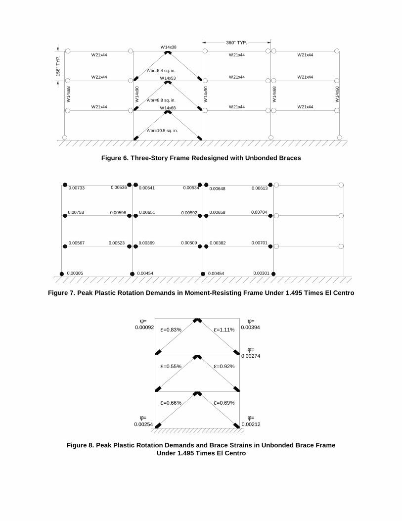
Figure 6. Three-Story Frame Redesigned with Unbonded Braces
Figure 7. Peak Plastic Rotation Demands in Moment-Resisting Frame Under 1.495 Times El Centro
Figure 8. Peak Plastic Rotation Demands and Brace Strains in Unbonded Brace FrameUnder 1.495 Times El Centro
156"
TYP
. W21x44 W21x44
W21x44 W14x53 W21x44
W21x44
W21x44
W21x44 W14x68 W21x44 W21x44
W14
x68
W14
x90
W14
x90
W14
x68
W14
x68
360" TYP.W14x38
A'br=5.4 sq. in.
A'br=8.8 sq. in.
A'br=10.5 sq. in.
0.00733
0.00753
0.00567
0.003010.004540.004540.00305
0.00536
0.00596
0.00523
0.00641
0.00651
0.00369
0.00534
0.00592
0.00509
0.00648
0.00658
0.00382
0.00613
0.00704
0.00701
0.002120.00254
0.00274
ε=0.66% ε=0.69%
ε=0.55% ε=0.92%
ε=0.83% ε=1.11%
φ= φ=
φ=
0.003940.00092φ= φ=

those in SMRF which developed plastic rotations of 2 to 3% radian. Increasing the beam and column sizes at thebraced bay of the UBF (which will cause only a slightincrease in cost) could make this frame virtually damagefree, even against the Kobe record.
Results from Large-Scale Tests
Introduction
Three large-scale unbonded braces were tested recently inthe Structures Laboratory of the Department of Civil &Environmental Engineering at the University of Californiaat Berkeley. The test program was initiated to support thedesign of the new UC Davis Plant & Environmental Sci-ences Replacement Facility (see next section). The mainpurpose of the tests was to demonstrate the behavior offull-size braces under a increasing-amplitude cyclic load-ing history, derived from the protocol used in the Phase 2SAC Steel Project. (This load pattern is referred to here asthe SAC Basic Loading History). The behavior of thebraces under other types of loading (SAC near-field proto-col, simulated earthquake loading, and low-cycle fatigue)was also investigated.
Test Specimens and Test Program
All of the specimens were the same overall length, approx-imately 14.75 ft., but each had an axial load-carrying steelcore plate with a different cross-sectional area. The threespecimens, denoted T-1, T-2, and T-3, had core areas of4.5 in2, 6.0 in2, and 8.0 in2, respectively, and yield forcesof approximately 270 kips, 360 kips, and 470 kips, respec-tively. Specimens T-1 and T-2 had a rectangular yieldingcore section, and the core specimen of specimen T-3 was acruciform (+) cross-section. The core plate and end con-nection splice plates were manufactured from JIS (Japa-nese Industrial Standard) grade SM490A steel, which isequivalent to the A913 steel recently introduced into theUnited States market. Coupon tests of the steel indicatedan average yield stress of 60.7 ksi, an average ultimatestress of 78.2 ksi, and an average ultimate elongation of 28percent.
The test program was as follows:
• Specimen T-1:- SAC Basic Loading History- SAC Near-Field Loading History
• Specimen T-2:- SAC Basic Loading History- Low-cycle fatigue test
• Specimen T-3:- SAC Basic Loading History- Earthquake displacement records
The “SAC” loading histories were derived from the stan-dard protocol specified for steel moment connections inthe SAC Steel Project test programs. This loading protocolis expressed in terms of interstory drift; for the purposes ofthese tests, interstory drift in one of the braced frame fromthe UC Davis building was converted to an equivalentstrain in the full-length brace, then this strain time historywas applied to the test brace. The target interstory driftwas approximately 3 percent, consistent with the largestdrift computed for the UC Davis building under the MCEground motions. The corresponding brace strain wasapproximately 2 percent, varying slightly between the dif-ferent test specimens because each had a slightly differentyielding length. Figure 9 shows the SAC Basic LoadingHistory.
The SAC Near-Field Loading History, shown in Fig. 10,was developed to represent the type of biased responsethat might be anticipated in a structure subjected to a near-field velocity pulse. The maximum displacement in thisloading history corresponds to an interstory drift of 6 per-cent. The corresponding brace strain was 4 percent.
Figure 9. SAC Basic Loading History
0
0.375
3.0
2.0
1.5
1.00.750.50
6 6 6 4 2 2 2
No. of Cycles
Interstory Drift [%]

The earthquake displacement time histories were derivedfrom a simplifed analysis of a 5-story building subjected tothe 1940 El Centro NS record and the 1994 Sylmar NSrecord. An equivalent initial period and yield base shearcoefficient were selected appropriate to a 5-story bracedsteel frame, and then a nonlinear time history analysis wasperformed on the equivalent single degree of freedom sys-tem. The resulting displacement was then multiplied by 3/2 and divided by the total assumed building height toobtain a mean interstory drift time history. Finally, thiswas converted to an equivalent brace strain in the testspecimen.
The low-cycle fatigue test consisted of 18 tension-com-pression cycles at the MCE interstory drift of 3 percent,corresponding to a brace strain of approximately 2 per-cent. This test was initiated after the SAC Basic LoadingHistory was completed, so the specimen had already expe-rienced 2 cycles at the MCE drift.
Test Results
All of the specimens exhibited stable hysteretic behaviorduring the cyclic and earthquake loading tests, and onlyspecimen T-2 failed, as a result of 17 cycles at 2 percentaxial strain in the low-cycle fatigue test.
Figures 11 through 13 show the force-displacement rela-tionship measured during the SAC Basic Load History testfor specimens T-1 through T-3, respectively. It is clear thateach of the braces sustained the Basic Loading Historywith very little change in properties. Also, the yield forcevalues observed in the tests are very similar to those pre-dicted based on coupon testing, providing confidence inthe reliability of coupon testing for predicting bracebehavior. It should be noted that there was some bolt slip
Figure 10. SAC Near-Field Loading History
0
-1.67
3.34
5.01
1.67
Bra
ce D
efor
mat
ion
(inch
es) tension
compression
during the tests of specimen T-3, when the force devel-oped in the brace was greater than 600 kips. The bolt slipis evident in the sudden drops in load in the hysteresis loopfor T-3 (Fig. 13).
It can be seen that in each of the tests, the brace force incompression is slightly higher than that in tension, perhapscaused in part by variations in the cross-sectional area andtherefore the true stress on the central steel core as it yieldsin tension and compression within the concrete-filled tube.The difference between the peak tension load and the peakcompression load ranged between 7.3 and 9.5 percent forthe three specimens. A simple calculation shows that thedifference between engineering stress and true stress at astrain of 2 percent does not entirely account for theobserved difference between compression and tensionstress, so there are likely other mechanisms at work, suchas compression of spacing materials inside the tube, orconstraint on the steel core when it goes into compressioninside of the tube.
The force-displacement relationship for the SAC Near-Field Loading History test of specimen T-1 is shown inFig. 14. It can be seen that the specimen exhibited stablebehavior even when cycled about an offset displacementof 3.34 inche, and for a maximum tension displacement of4.84 inches, approximately two times the maximumdesign displacement for the brace.
The force-displacement relationship for the low-cyclefatigue test of specimen T-2 is provided in Fig. 15. Thebrace exhibited extremely stable cycle behavior with veir-tually no degradation of strength or stiffness for all of theloading cycles up to failure, with a fracture failure of thecore plate occuring inside the confining tube in the secondhalf of the 15th cycles. These 15 cycles, combined withthe two cycles at 2 percent brace strain in the Basic Load-ing History, give a total of 17-1/2 cycles to failure at abrace cyclic strain of 2 percent.
The force-displacement relationship for the earthquakedisplacement test corresponding to the 1994 Sylmar recordis shown in Fig. 16. Again, the specimen exhibited verypredictable hysteretic behavior with no strength or stiff-ness degradation. Although the lower-amplitude responsefrom the El Centro test is not shown here, the brace force-displacement was similar to that observed in the small-amplitude cycles during the Sylmar test. The results fromthese earthquake tests will be used to calibrate analyticalmodels for unbonded braces for future studies.
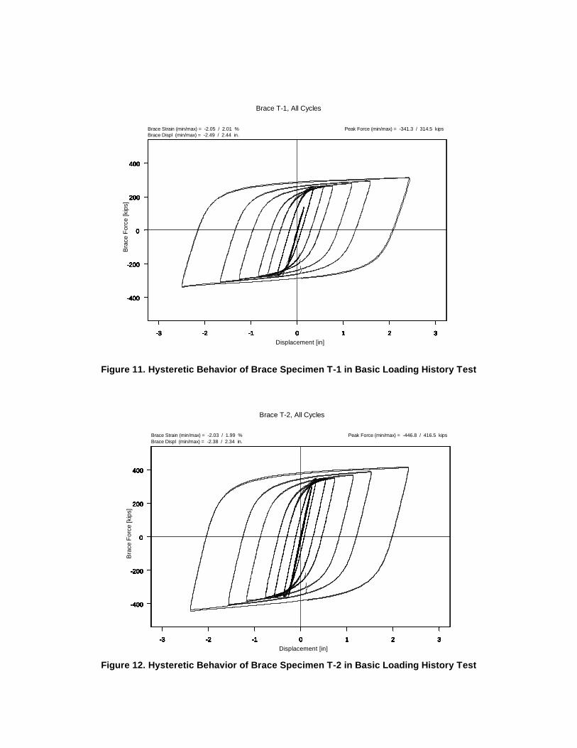
Figure 11. Hysteretic Behavior of Brace Specimen T-1 in Basic Loading History Test
Figure 12. Hysteretic Behavior of Brace Specimen T-2 in Basic Loading History Test
-3 -2 -1 0 1 2 3
-400
-200
0
200
400
-3 -2 -1 0 1 2 3
-400
-200
0
200
400
-3 -2 -1 0 1 2 3
-400
-200
0
200
400
-3 -2 -1 0 1 2 3
-400
-200
0
200
400
-3 -2 -1 0 1 2 3
-400
-200
0
200
400
-3 -2 -1 0 1 2 3
-400
-200
0
200
400
-3 -2 -1 0 1 2 3
-400
-200
0
200
400
-3 -2 -1 0 1 2 3
-400
-200
0
200
400
-3 -2 -1 0 1 2 3
-400
-200
0
200
400
-3 -2 -1 0 1 2 3
-400
-200
0
200
400
Brace Strain (min/max) = -2.05 / 2.01 %Brace Displ (min/max) = -2.49 / 2.44 in.
Peak Force (min/max) = -341.3 / 314.5 kips
Displacement [in]
Bra
ce F
orce
[kip
s]
Brace T-1, All Cycles
-3 -2 -1 0 1 2 3
-400
-200
0
200
400
-3 -2 -1 0 1 2 3
-400
-200
0
200
400
-3 -2 -1 0 1 2 3
-400
-200
0
200
400
-3 -2 -1 0 1 2 3
-400
-200
0
200
400
-3 -2 -1 0 1 2 3
-400
-200
0
200
400
-3 -2 -1 0 1 2 3
-400
-200
0
200
400
-3 -2 -1 0 1 2 3
-400
-200
0
200
400
-3 -2 -1 0 1 2 3
-400
-200
0
200
400
-3 -2 -1 0 1 2 3
-400
-200
0
200
400
-3 -2 -1 0 1 2 3
-400
-200
0
200
400
Brace Strain (min/max) = -2.03 / 1.99 %Brace Displ (min/max) = -2.38 / 2.34 in.
Peak Force (min/max) = -446.8 / 416.5 kips
Displacement [in]
Bra
ce F
orce
[kip
s]
Brace T-2, All Cycles
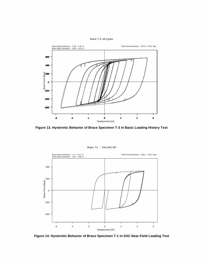
Figure 13. Hysteretic Behavior of Brace Specimen T-3 in Basic Loading History Test
Figure 14. Hysteretic Behavior of Brace Specimen T-1 in SAC Near-Field Loading Test
-3 -2 -1 0 1 2 3
-600
-400
-200
0
200
400
600
-3 -2 -1 0 1 2 3
-600
-400
-200
0
200
400
600
-3 -2 -1 0 1 2 3
-600
-400
-200
0
200
400
600
-3 -2 -1 0 1 2 3
-600
-400
-200
0
200
400
600
-3 -2 -1 0 1 2 3
-600
-400
-200
0
200
400
600
-3 -2 -1 0 1 2 3
-600
-400
-200
0
200
400
600
-3 -2 -1 0 1 2 3
-600
-400
-200
0
200
400
600
-3 -2 -1 0 1 2 3
-600
-400
-200
0
200
400
600
-3 -2 -1 0 1 2 3
-600
-400
-200
0
200
400
600
-3 -2 -1 0 1 2 3
-600
-400
-200
0
200
400
600
Brace Strain (min/max) = -1.98 / 1.94 %Brace Displ (min/max) = -2.69 / 2.63 in.
Peak Force (min/max) = -627.9 / 573.2 kips
Displacement [in]
Bra
ce F
orce
[kip
s]
Brace T-3, All Cycles
-6 -4 -2 0 2 4 6
-400
-200
0
200
400
Brace Strain (min/max) = -1.4 / 4.11 %Brace Displ (min/max) = -1.65 / 4.84 in.
Peak Force (min/max) = -326.2 / 330.1 kips
Displacement [in]
Bra
ce F
orce
[kip
s]
Brace T1 - Test SAC-NF

Figure 15. Hysteretic Behavior of Brace Specimen T-2 During Low-Cycle Fatigue Test(15 complete cycles shown in the figure prior to failure)
Figure 16. Hysteretic Behavior of Brace Specimen T-3 During Sylmar Earthquake Test
-3 -2 -1 0 1 2 3
-400
-200
0
200
400
Brace Strain (min/max) = -2.03 / 2.12 %Brace Displ (min/max) = -2.39 / 2.5 in.
Peak Force (min/max) = -462.9 / 424.3 kips
Displacement [in]
Bra
ce F
orce
[kip
s]
Brace T2 - Test 8
-3 -2 -1 0 1 2 3
-600
-400
-200
0
200
400
600
Brace Strain (min/max) = -1.48 / 1.77 %Brace Displ (min/max) = -2.02 / 2.41 in.
Peak Force (min/max) = -601.6 / 564 kips
Displacement [in]
Bra
ce F
orce
[kip
s]
Brace T3 - Test SYL2

Conclusions
The results for all three test specimens indicated very goodagreement with the elastic stiffness and yield force pre-dicted based on coupon testing. The SAC Basic LoadingHistory tests showed the unbonded braces capable of sta-ble cyclic hysteretic behavior over the entire range of dis-placement amplitudes. Finally, the behavior of the bracesin the additional tests indicated their resistance to fracture,even after severe loading, and their stable, predictableforce-displacement characteristics, even under non-cyclictransient loadings such as earthquakes.
First Application in the United States:UC Davis Plant & Environmental Sciences
Introduction
The Plant & Environmental Sciences Replacement Facil-ity is a three-story laboratory project located at the Univer-sity of California Davis campus. It is a steel building withcomposite metal deck construction and has a total floorarea of 125,000 square feet. The overall building isroughly “C” shaped in plan (Fig. 17). A seismic jointdivides the building into two separate “L-shaped” struc-tures.
A lateral system using Eccentrically Braced Frame (EBF)was selected over a steel moment frame system based onthe willingness of the architect to incorporate braces and a
cost- benefit study comparing the two systems. The bracedbays were strategically located after careful coordinationwith the architect so that maximum program flexibility oflaboratory spaces (brace free laboratory suites) could beachieved.
To help optimize braced frame locations and to limit therotational response of the structure, ETABS models of theeast and west buildings were developed. The relative stiff-ness of the braced frames was first adjusted to get the cen-ter of rigidity to closely correspond to the center of mass.Dynamic analyses were then performed to capture thedynamic characteristics of the structures. As expected, thebraces at the perimeter had to be increased in sizes to bal-ance the rotational stiffnesses of the buildings.
Lateral Systems Comparison – Pushover Analyses
The Eccentrically Braced Frame (EBF) system wasselected as the base seismic system for the project. Inorder to justify the inclusion of the Unbonded BracedFrame (UBF) as an alternate, nonlinear static pushoveranalyses were conducted to compare the performance ofEBF, UBF and CBF (Concentrically Braced Frame) struc-tural systems. A typical bay at the perimeter of the EastWing was picked for this exercise. (Note that this bay wasnot designed for the same level of lateral force in each ofthe three systems, because the number and distribution ofbraced bays was slightly different for each system.)
Figure 17. Plan of UC Davis Plant & Environmental Sciences Replacement Facility

For the purposes of evaluating the behavior of the differentbraced framing systems, the “performance point” isdefined as the intersection between the demand spectrumand capacity spectrum of a particular building. A responsespectrum is determined for the site considering near sourcefactors, seismic zone, and performance objectives. Thisspectrum typically assumes the structure has 5% dampingand will behave elastically during an earthquake. Build-ings are expected to have inelastic response during adesign earthquake event, so the spectrum is subsequentlybe scaled to account for this. As earthquake intensityincreases, the building responds with increasing inelasticbehavior. The effect is to then increase the damping andthe effective period, leading to a response that is typicallysmaller than for a building with less damping or a shorterperiod. The response spectrum is scaled to the designspectrum based on the level of damping achieved when thebuilding capacity matches the demand placed on it. Sincethe demand will depend on this damping level, the solu-tion of this performance point is iterative. The perfor-mance point represents the maximum structuraldisplacement expected for the demand earthquake groundmotion. Note that this may not coincide with the maxi-mum force level since it may occur after yielding and adrop in load capacity.
Table 2 summarizes the structural framing used in each ofthe braced frame systems considered. All of the membersare assumed to be Grade 50 except the tube sections areassumed to have a yield stress of 46 ksi. A total of sixmasses of 0.9 kips/(386.4 in/sec2) each are placed on col-umn line locations on each floor.
Results of the pushover analyses and performance pointsfor each system (denoted by l) are shown in Fig. 18.
The unbonded brace system resists the most force (baseshear) because it one of a fewer number of braced framesrequired in the building as compared with the other sys-tems. It exhibits the smoothest response in the pushoveranalysis, with the CBF system demonstrating successivemember failures in the incremental elastic analysis. TheEBF system reaches the performance point in a smoothmanner similar to the UBF, but for increased demand itsstrength drops dramatically when the link capacity isexceeded. The CBF system has several braces lose theircapacity before the performance point is reached. Whilethere is no collapse at this point, substantial damage wouldoccur to this system at this design earthquake level.
Table 3 summarizes the differences in the structural sys-tems at their individual performance points. Each systemwill satisfy the given performance objective with the quan-tities given in the Table.
The unbonded brace structural system has the lowest roofdisplacement and the highest base shear to weight ratio.This means that it has displaced the least and has the high-est reserve capacity after the design earthquake hasoccurred. The effective period, Teff, will generally belargest for the system that has the most damage. Noticethat this quantity is smallest for the unbonded brace sys-tem. In addition, the unbonded braces are only strainedone-fifth the amount of the concentric braces. The linkbeam in the EBF system has an even larger strain. Whilethe strain in the link beams of the EBF system seem largerelative to the strains in the braces of the CBF system, theEBF behavior is better than the CBF behavior. The EBFscheme achieves the performance level at lower roof dis-placement and higher base shear. The larger strain can beattributed to the fact that the energy dissipation in the EBFsystem is more concentrated than in the CBF system.
CBF EBF UBFColumns Story 3 W12x136 W12x152 W12x136
Story 2 W12x136 W12x152 W12x136Story 1 W12x136 W12x152 W12x136
Beams Roof W16x67 W14x53 W16x67Floor 3 W16x67 W14x53 W16x67Floor 2 W16x77 W14x53 W16x77
Braces Story 3 TS7x7x1/4 W10x60 5 sq. in.Story 2 TS7x7x3/8 W10x60 7 sq. in.Story 1 TS7x7x1/2 W10x60 8.5 sq. in.
Table 2: Structural Framing for Three Braced Frame Systems Considered
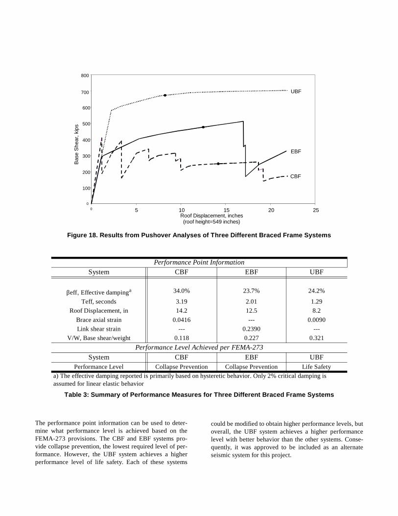
The performance point information can be used to deter-mine what performance level is achieved based on theFEMA-273 provisions. The CBF and EBF systems pro-vide collapse prevention, the lowest required level of per-formance. However, the UBF system achieves a higherperformance level of life safety. Each of these systems
could be modified to obtain higher performance levels, butoverall, the UBF system achieves a higher performancelevel with better behavior than the other systems. Conse-quently, it was approved to be included as an alternateseismic system for this project.
Figure 18. Results from Pushover Analyses of Three Different Braced Frame Systems
Performance Point InformationSystem CBF EBF UBF
βeff, Effective dampinga 34.0% 23.7% 24.2%
Teff, seconds 3.19 2.01 1.29Roof Displacement, in 14.2 12.5 8.2
Brace axial strain 0.0416 --- 0.0090Link shear strain --- 0.2390 ---
V/W, Base shear/weight 0.118 0.227 0.321Performance Level Achieved per FEMA-273
System CBF EBF UBFPerformance Level Collapse Prevention Collapse Prevention Life Safety
a) The effective damping reported is primarily based on hysteretic behavior. Only 2% critical damping is assumed for linear elastic behavior
Table 3: Summary of Performance Measures for Three Different Braced Frame Systems
0
100
200
300
400
500
600
700
800
0 5 10 15 20 25Roof Displacement, inches(roof height=549 inches)
Bas
e S
hear
, kip
s
UBF
EBF
CBF

Conclusions
This paper summarized a number of recent activitiesrelated to the implementation of unbonded braces withinUnited States seismic design practices. First, a study wassummarized which is intended to evaluate the suitability ofusing code-consistent equivalent static force procedures todesign frames incorporating buckling-resistant unbondedbraces. The frame design investigated was compared withthat of a steel moment-resisting frame previously studiedin the FEMA/SAC project. Because the SMRF frame sizewas controlled by drift requirements, the frame exhibited asignificant overstrength compared with the minimum yieldbase shear. The UBF, designed according to provision forEBFs, did not suffer from this limitation and therefore hada much lower yield base shear and significantly less steelin the lateral load-resisting system. The results of a briefseries of nonlinear time history analyses also showed thatthe UBF performed better than the SMRF in terms ofinterstory drift and base shear. This preliminary study iscurrently being extended to investigate taller structures(including the 9-story steel moment frame used in theFEMA/SAC project) and to develop design procedures toachieve higher performance levels and optimal framedesigns within the context of U.S. building codes.
Parallel to the ongoing design studies, large-scale tests ofunbonded braces have been carried out to demonstrate thestable hysteretic behavior that can be achieved with theseelements. Three braces were subjected to a wide range oftests and showed predictable behavior and substantialoverstrength in terms of both displacement and energy dis-sipation capacity.
Finally, a series of design studies in support of the firstapplication of unbonded braces in the United States wasdescribed.
Acknowledgement
The authors are grateful to Mr. Kentaro Makishima, agraduate student at Tokyo Institute of Technology, for hissignificant assistance in computer analyses of the studybuildings.
Several engineers in the California offices of Ove Arupand Partners contributed to the summary of the designstudies for the U.C. Davis Plant & Enviromental SciencesReplacement Facility, including Larry Chambers, Dr.Andres Carlson, and Senior Associate Atila Zekioglu, S.E.Their valuable contributions are sincerely appreciated.
The cooperation of the staff at U.C. Davis in disseminatinginformation about the design process used for the Plant &Environmental Sciences Replacement Facility is greatlyappreciated.
References
Watanabe, A., Hitomi, Y., Saeki, E., Wada, A., and Fujim-oto, M., 1988, “Properties of Brace Encased in Buckling-Restraining Concrete and Steel Tube,” Proceedings ofNinth World Conference on Earthquake Engineering,Tokyo-Kyoto, Japan, Paper No. 6-7-4, Vol. IV, pp. 719-724.
Reina, P, and Normile, D., “Fully Braced for Seismic Sur-vival,” Engineering News Record, July 21, 1997, pp. 34-36.
Wada, A., Iwata, M., and Huang, Y.H., 1997, “SeismicDesign Trend of Tall Buildings After the Kobe Earth-quake,” Proceedings of International Post-SMiRT Confer-ence Seminar on Seismic Isolation, Passive EnergyDissipation, and Control of Vibrations of Structures,Taormina, Italy, August 25-27.
Building Letter, 1997, Building Center of Japan, Ministryof Construction, Tokyo, Japan.
Uniform Building Code, 1994, International Conference ofBuilding Officials, Whittier, CA.
Scholl, R., 1993, “Design Criteria for Yielding and Fric-tion Energy Dissipators,” ATC 17-1: Proceedings of Semi-nar on Seismic Isolation, Passive Energy Dissipation, andActive Control, Applied Technology Council, San Fran-cisco, CA, Vol. 2, pp. 485-495.
SAC, 1999, “Model Building Designs for Three U.S. Cit-ies,” SAC Background Document, in preparation.
Kasai, K., Fu, Y., and Watanabe, A., 1998, “Passive Con-trol Systems for Seismic Damage Mitigation,” Journal ofStructural Engineering, American Society of Civil Engi-neers, Vol. 124, No. 5, May, pp. 501-512.
Kasai, K. and Goyal, A., 1993, “Link Length Design andEBF Seismic Performance,” Proceedings of StructuresCongress ‘93, American Society of Civil Engineers, Irv-ine, CA, Vol. 1, pp. 397-402.