shake table testing of concentrically braced steel · pdf file1 shake table testing of...
TRANSCRIPT
1
SHAKE TABLE TESTING OF CONCENTRICALLY BRACED STEEL
FRAMES WITH VARIOUS GUSSET PLATE DESIGNS
Brian BRODERICK1, Jamie GOGGINS2, Ahmed ELGHAZOULI3, Darko BEG4, Alan
HUNT5, Suhaib SALAWDEH6 and Phillippe MONGABURE7
ABSTRACT
This paper describes a set of shake table tests investigating the ultimate behaviour of
concentrically braced frames (CBFs) with hollow section bracing members and gusset plate
connections. Twelve separate experiments were performed on the Azalee seismic testing facility at
CEA Saclay, France. The project (entitled BRACED) was carried out as part of the EC FP7 project
SERIES (Seismic Engineering Research Infrastructures for European Synergies). The experimental
programme was designed to validate empirical models for brace ductility capacity and to assess the
influence of gusset plate detailing on brace and frame performance under realistic inelastic dynamic
seismic response conditions. The properties of the brace members and gusset plate connections were
varied between experiments to examine a range of feasible properties and to investigate the influence
of conventional and improved design details on frame response. The brace-gusset plate specimens
possessed a range of properties covering the feasible ranges of the following parameters: non-
dimensional brace slenderness, λnom; brace cross-section slenderness, b/t; and gusset plate balance
factor, βww. All specimens were tested under uniaxial seismic excitation using the same earthquake
record scaled to three different levels: (i) low- level with elastic response, (ii) medium-level with brace
buckling and yielding, and (iii) high-level with brace fracture. A wide range of response variables
were measured in each test, including table and response accelerations and displacements, brace
elongation and axial force, and strains in the brace member and gusset plate. Measured brace
displacement ductility capacities varied between 2.9 and 12.0, with a mean value of 7.5. The variation
between the values identified in each test is attributed to the main test specimen parameters: member
slenderness, cross-section slenderness, connection type and gusset plate detailing.
INTRODUCTION
Concentrically braced frames (CBFs) provide efficient earthquake resistance in steel structures:
combining the stiffness and strength required for small, frequent earthquakes, with the potential for a
dissipative response that ensures adequate performance during larger events. During severe seismic
1 Professor, Trinity College Dublin, Ireland, [email protected] 2 Lecturer, NUI Galway, Ireland, [email protected] 3 Professor, Imperial College London, UK, [email protected] 4 Professor, University of Ljubliana, Slovenia, [email protected] 5 Research Associate, Trinity College Dublin, Ireland, [email protected] 6 Lecturer, NUI Galway, Ireland, [email protected] 7 Engineer, EMSI, CEA Saclay, France, [email protected]
2
loading, the diagonal bracing members in CBFs experience repeated cycles involving yielding in
tension and member buckling in compression, and their performance is known to depend on local and
global member slenderness and end restraint, amongst other factors (Elghazouli, 2003). Previous
experimental studies examining inelastic behaviour of bracing members have mainly employed quasi-
static cyclic loading. Early studies examined the load-displacement hysteretic response which was
shown to be most strongly influenced by global slenderness (Popov and Black, 1981). Subsequently
both global and local slenderness were found to influence fracture life (Tremblay, 2002), and
empirical expressions for the fracture life and ductility capacity of hollow section bracing members
have been proposed (Goggins et al, 2006; Nip et al, 2010). At large storey drifts, the gusset-plate
connections employed to connect bracing members to the beams and columns of a CBF must
accommodate large brace end-rotations, normally involving the formation of a stable ductile plastic
hinge within the gusset plate, and prevent gusset plate buckling in compression or yielding in tension
(AISC, 2005). Unfortunately, the design guidance and practice employed to meet these multiple
requirements can lead to over-sized gusset plates that reduce brace ductility capacity. Balanced gusset
plate detailing rules have been recommended which result in more efficient connection designs while
improving the seismic performance of the CBF overall (Roeder et al, 2011). This balanced design
approach develops the capacity design approach through the balancing of yield mechanisms in both
the brace and the connection. The methodology distinguishes between yielding of an element which
implies significant changes in stiffness and inelastic deformation while maintaining reasonably stable
resistance, and failure modes leading to fracture initiation which imply reduced resistance and inelastic
deformation capacity. In brace connections, this can be manifested by permitting tensile yielding of
the gusset plate, but only after yielding of the brace member itself has occurred. The lower tensile
resistance of the gusset plate in turn helps to protect against other brittle failure modes, including local
failure at the connection of the gusset plate to the beam and column members, and delay brace
fracture. In an extensive experimental study of 34 full-scale 1-, 2- and 3-storey SCBFs (Roeder, 2011)
found that the balanced design method greatly increases the deformation capacity of SCBF systems.
When the balanced design method is applied to gusset plates in CBF design, it typically results in
smaller, thinner gusset plates and are more susceptible to plate buckling, which is an unstable and
hence unacceptable failure mode. This can be avoided by adopting an alternative detailing proposal by
Roeder et al. (2006) which theorises an elliptical shape yield line in the gusset plate, rather than the
conventional standard linear clearance detail. These details are illustrated in Figure 3 which
demonstrates how the balanced design method incorporating the elliptical clearance model and the
conventional design approach incorporating the SLC method are implemented in the specimens tested
in the BRACED project shake table tests.
EXPERIMENTAL METHODOLOGY
The BRACED Project was initiated as part of the Transnational Access programme offered by the
European Commission’s Seventh Framework Programme (FP7) project SERIES (Seismic Engineering
Research Infrastructures for European Synergies). The programme of shake table tests executed within
the BRACED project addressed three principal objectives:
• To examine the validity of predictive formulae for the stiffness, resistance and ductility of
individual brace members and whole CBFs under realistic dynamic response conditions.
• To assess the influence of different gusset plate designs on the dynamic response of CBFs to
earthquake ground motion.
• To obtain experimental data for the validation of numerical modelling techniques for the
earthquake response of CBFs.
The experiments were carried out on the AZALEE shake table at the TAMARIS Laboratory in the
Laboratoire d'Etudes de Mécanique Sismique (EMSI) at CEA Saclay, France. The AZALEE platform
has an area of 6×6 m and can accommodate test masses up to 100 tonnes. It is capable of triaxial
excitations up to 1.0g, offering six degrees of freedom and maximum longitudinal and lateral
displacement of ±125 mm.
Each experiments examined the earthquake response of a model test frame incorporating a pair of
brace specimens. The test frame (or ‘mock-up’) used for the BRACED experiments on the Azalee
B.M. Broderick et al 3
shake table was designed to facilitate the testing of multiple pairs of brace-gusset plate specimens, by
allowing the specimens to be exchanged between experiments. The brace member and connection
details were varied between experiments to investigate the range of global and local member
slenderness found in European design practice, and to assess the effect of conventional and novel
gusset plate designs. In each experiment, three separate earthquake tests were performed with table
excitations scaled to produce elastic response, brace buckling and/or yielding and brace fracture. The
principal outcomes included measurements of the displacement ductility capacity of the brace
specimens; an evaluation of the influence of gusset plate detailing on connection ductility;
observations on the contributions of brace and connection yielding to overall inelastic deformation of
CBFs; measurements of equivalent viscous damping in CBFs; assessment and improvement of
Eurocode 8 design guidance for CBFs; and validation of numerical models.
TEST PROGRAMME
To address project objectives, three different test parameters were varied between tests: brace
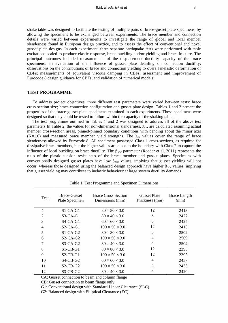
cross-section size; brace connection configuration and gusset plate design. Tables 1 and 2 present the
properties of the brace-gusset plate specimens examined in each experiments. These specimens were
designed so that they could be tested to failure within the capacity of the shaking table.
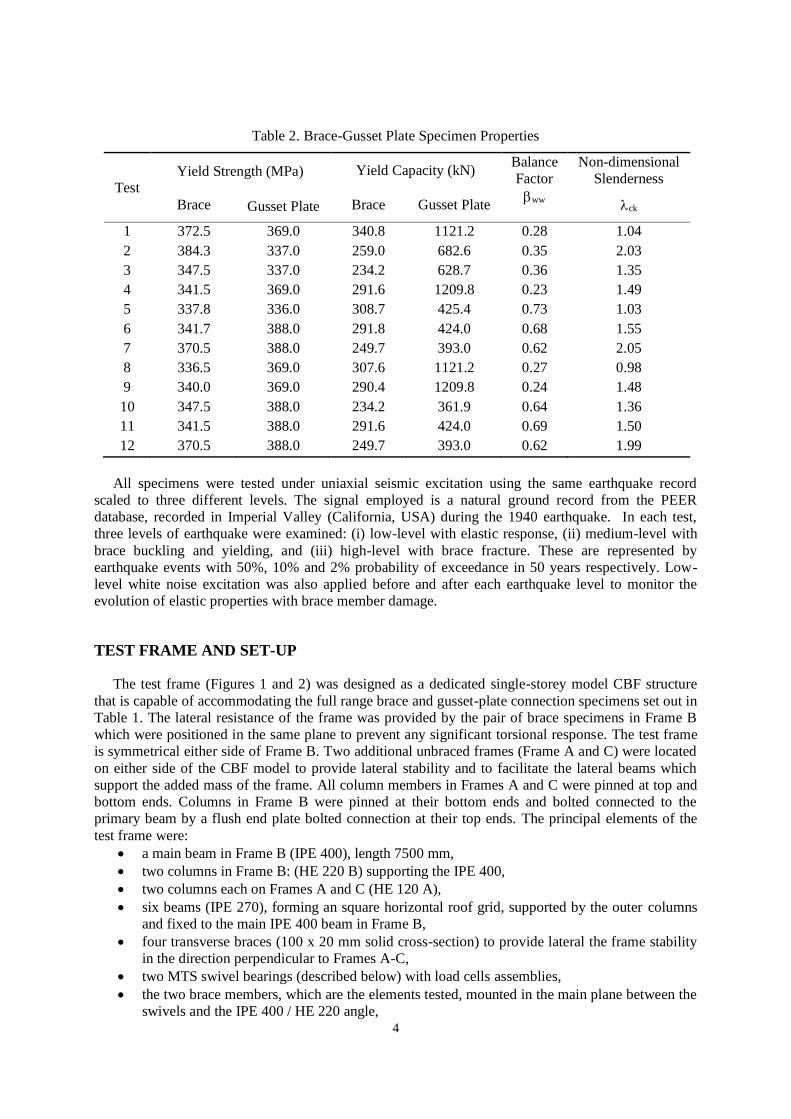
The test programme outlined in Tables 1 and 2 was designed to address all of the above test
parameters In Table 2, the values for non-dimensional slenderness, λck, are calculated assuming actual
member cross-section areas, pinned-pinned boundary conditions with bending about the minor axis
(K=1.0) and measured brace member yield strengths. The λck values cover the range of brace
slenderness allowed by Eurocode 8. All specimens possessed Class 1 cross-sections, as required for
dissipative brace members, but the higher values are close to the boundary with Class 2 to capture the
influence of local buckling on brace ductility. The ww parameter (Roeder et al, 2011) represents the
ratio of the plastic tension resistances of the brace member and gusset plates. Specimens with
conventionally designed gusset plates have low ww values, implying that gusset yielding will not
occur, whereas those designed using the balanced design approach have higher ww values, implying
that gusset yielding may contribute to inelastic behaviour at large system ductility demands
Table 1. Test Programme and Specimen Dimensions
Test Brace-Gusset
Plate Specimen
Brace Cross Section
Dimensions (mm)
Gusset Plate
Thickness (mm)
Brace Length
(mm)
1 S1-CA-G1 80 × 80 × 3.0 12 2413
2 S3-CA-G1 80 × 40 × 3.0 8 2427
3 S4-CA-G1 60 × 60 × 3.0 8 2425
4 S2-CA-G1 100 × 50 × 3.0 12 2413
5 S1-CA-G2 80 × 80 × 3.0 5 2502
6 S2-CA-G2 100 × 50 × 3.0 4 2509
7 S3-CA-G2 80 × 40 × 3.0 4 2504
8 S1-CB-G1 80 × 80 × 3.0 12 2395
9 S2-CB-G1 100 × 50 × 3.0 12 2395
10 S4-CB-G2 60 × 60 × 3.0 4 2437
11 S2-CB-G2 100 × 50 × 3.0 4 2433
12 S3-CB-G2 80 × 40 × 3.0 4 2420
CA: Gusset connection to beam and column flange
CB: Gusset connection to beam flange only
G1: Conventional design with Standard Linear Clearance (SLC)
G2: Balanced design with Elliptical Clearance (EC)
4
Table 2. Brace-Gusset Plate Specimen Properties
Test
Yield Strength (MPa) Yield Capacity (kN) Balance
Factor
Non-dimensional
Slenderness
Brace
Gusset Plate Brace
Gusset Plate ww
ck
1 372.5 369.0 340.8 1121.2 0.28 1.04
2 384.3 337.0 259.0 682.6 0.35 2.03
3 347.5 337.0 234.2 628.7 0.36 1.35
4 341.5 369.0 291.6 1209.8 0.23 1.49
5 337.8 336.0 308.7 425.4 0.73 1.03
6 341.7 388.0 291.8 424.0 0.68 1.55
7 370.5 388.0 249.7 393.0 0.62 2.05
8 336.5 369.0 307.6 1121.2 0.27 0.98
9 340.0 369.0 290.4 1209.8 0.24 1.48
10 347.5 388.0 234.2 361.9 0.64 1.36
11 341.5 388.0 291.6 424.0 0.69 1.50
12 370.5 388.0 249.7 393.0 0.62 1.99
All specimens were tested under uniaxial seismic excitation using the same earthquake record
scaled to three different levels. The signal employed is a natural ground record from the PEER
database, recorded in Imperial Valley (California, USA) during the 1940 earthquake. In each test,
three levels of earthquake were examined: (i) low-level with elastic response, (ii) medium-level with
brace buckling and yielding, and (iii) high-level with brace fracture. These are represented by
earthquake events with 50%, 10% and 2% probability of exceedance in 50 years respectively. Low-
level white noise excitation was also applied before and after each earthquake level to monitor the
evolution of elastic properties with brace member damage.
TEST FRAME AND SET-UP
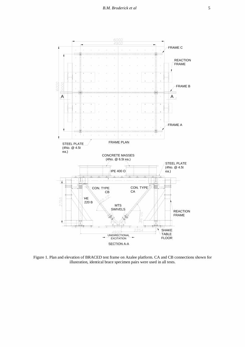
The test frame (Figures 1 and 2) was designed as a dedicated single-storey model CBF structure
that is capable of accommodating the full range brace and gusset-plate connection specimens set out in
Table 1. The lateral resistance of the frame was provided by the pair of brace specimens in Frame B
which were positioned in the same plane to prevent any significant torsional response. The test frame
is symmetrical either side of Frame B. Two additional unbraced frames (Frame A and C) were located
on either side of the CBF model to provide lateral stability and to facilitate the lateral beams which
support the added mass of the frame. All column members in Frames A and C were pinned at top and
bottom ends. Columns in Frame B were pinned at their bottom ends and bolted connected to the
primary beam by a flush end plate bolted connection at their top ends. The principal elements of the
test frame were:
a main beam in Frame B (IPE 400), length 7500 mm,
two columns in Frame B: (HE 220 B) supporting the IPE 400,
two columns each on Frames A and C (HE 120 A),
six beams (IPE 270), forming an square horizontal roof grid, supported by the outer columns
and fixed to the main IPE 400 beam in Frame B,
four transverse braces (100 x 20 mm solid cross-section) to provide lateral the frame stability
in the direction perpendicular to Frames A-C,
two MTS swivel bearings (described below) with load cells assemblies,
the two brace members, which are the elements tested, mounted in the main plane between the
swivels and the IPE 400 / HE 220 angle,
B.M. Broderick et al 5
SECTION A-A
IPE 400 O
CON. TYPE
CB
CONCRETE MASSES
(4No. @ 6.5t ea.)
REACTION
FRAME
CON. TYPE
CA
HE
220 B
FRAME PLAN
A A
STEEL PLATE
(4No. @ 4.5t
ea.)
REACTION
FRAME
MTS
SWIVELS
FRAME C
FRAME A
FRAME B
STEEL PLATE
(4No. @ 4.5t
ea.)
UNIDIRECTIONAL
EXCITATION
SHAKE
TABLE
FLOOR
Figure 1. Plan and elevation of BRACED test frame on Azalee platform. CA and CB connections shown for
illustration, identical brace specimen pairs were used in all tests.
6
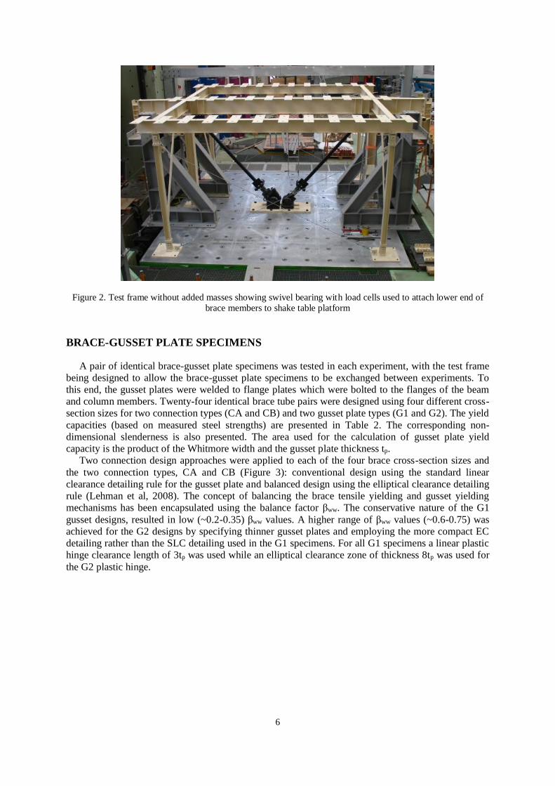
Figure 2. Test frame without added masses showing swivel bearing with load cells used to attach lower end of
brace members to shake table platform
BRACE-GUSSET PLATE SPECIMENS
A pair of identical brace-gusset plate specimens was tested in each experiment, with the test frame
being designed to allow the brace-gusset plate specimens to be exchanged between experiments. To
this end, the gusset plates were welded to flange plates which were bolted to the flanges of the beam
and column members. Twenty-four identical brace tube pairs were designed using four different cross-
section sizes for two connection types (CA and CB) and two gusset plate types (G1 and G2). The yield
capacities (based on measured steel strengths) are presented in Table 2. The corresponding non-
dimensional slenderness is also presented. The area used for the calculation of gusset plate yield
capacity is the product of the Whitmore width and the gusset plate thickness tp.
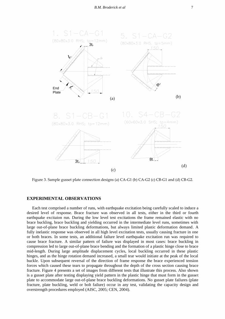
Two connection design approaches were applied to each of the four brace cross-section sizes and
the two connection types, CA and CB (Figure 3): conventional design using the standard linear
clearance detailing rule for the gusset plate and balanced design using the elliptical clearance detailing
rule (Lehman et al, 2008). The concept of balancing the brace tensile yielding and gusset yielding
mechanisms has been encapsulated using the balance factor βww. The conservative nature of the G1
gusset designs, resulted in low (~0.2-0.35) βww values. A higher range of βww values (~0.6-0.75) was
achieved for the G2 designs by specifying thinner gusset plates and employing the more compact EC
detailing rather than the SLC detailing used in the G1 specimens. For all G1 specimens a linear plastic
hinge clearance length of 3tp was used while an elliptical clearance zone of thickness 8tp was used for
the G2 plastic hinge.
B.M. Broderick et al 7
End
Plate
l
l
h
v
3tp
(a)
8tp
(b)
3tp
(c)
8t p
(d)
Figure 3. Sample gusset plate connection designs (a) CA-G1 (b) CA-G2 (c) CB-G1 and (d) CB-G2.
EXPERIMENTAL OBSERVATIONS
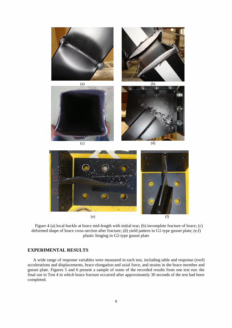
Each test comprised a number of runs, with earthquake excitation being carefully scaled to induce a
desired level of response. Brace fracture was observed in all tests, either in the third or fourth
earthquake excitaion run. During the low level test excitations the frame remained elastic with no
brace buckling, brace buckling and yielding occurred in the intermediate level runs, sometimes with
large out-of-plane brace buckling deformations, but always limited plastic deformation demand. A
fully inelastic response was observed in all high level excitation tests, usually causing fracture in one
or both braces. In some tests, an additional failure level earthquake excitation run was required to
cause brace fracture. A similar pattern of failure was displayed in most cases: brace buckling in
compression led to large out-of-plane brace bending and the formation of a plastic hinge close to brace
mid-length. During large amplitude displacement cycles, local buckling occurred in these plastic
hinges, and as the hinge rotation demand increased, a small tear would initiate at the peak of the local
buckle. Upon subsequent reversal of the direction of frame response the brace experienced tension
forces which caused these tears to propagate throughout the depth of the cross section causing brace
fracture. Figure 4 presents a set of images from different tests that illustrate this process. Also shown
is a gusset plate after testing displaying yield pattern in the plastic hinge that must form in the gusset
plate to accommodate large out-of-plane brace buckling deformations. No gusset plate failures (plate
fracture, plate buckling, weld or bolt failure) occur in any test, validating the capacity design and
overstrength procedures employed (AISC, 2005; CEN, 2004).
8
(a) (b)
(c)
(d)
(e) (f)
Figure 4 (a) local buckle at brace mid-length with initial tear; (b) incomplete fracture of brace; (c)
deformed shape of brace cross-section after fracture; (d) yield pattern in G1-type gusset plate; (e,f)
plastic hinging in G2-type gusset plate
EXPERIMENTAL RESULTS
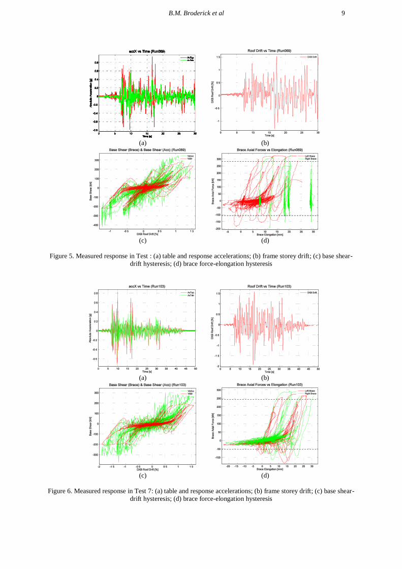
A wide range of response variables were measured in each test, including table and response (roof)
accelerations and displacements, brace elongation and axial force, and strains in the brace member and
gusset plate. Figures 5 and 6 present a sample of some of the recorded results from one test run: the
final run in Test 4 in which brace fracture occurred after approximately 30 seconds of the test had been
completed.
B.M. Broderick et al 9
(a) (b)
(c) (d)
Figure 5. Measured response in Test : (a) table and response accelerations; (b) frame storey drift; (c) base shear-
drift hysteresis; (d) brace force-elongation hysteresis
(a) (b)
(c) (d)
Figure 6. Measured response in Test 7: (a) table and response accelerations; (b) frame storey drift; (c) base shear-
drift hysteresis; (d) brace force-elongation hysteresis

10
Figure 7 compares the observed variation in maximum drift demand with peak ground
acceleration in each test. The results are grouped by brace cross-section size. The larger cross sections
(S1 and S2) display a mostly linear relationship between drift and pga, while the smaller cross sections
(S3 and S4) exhibit increasing drift values for higher pga. This behavior may be expected in short
period structures that are subjected to ground excitations substantially greater than those required for
initial yield.
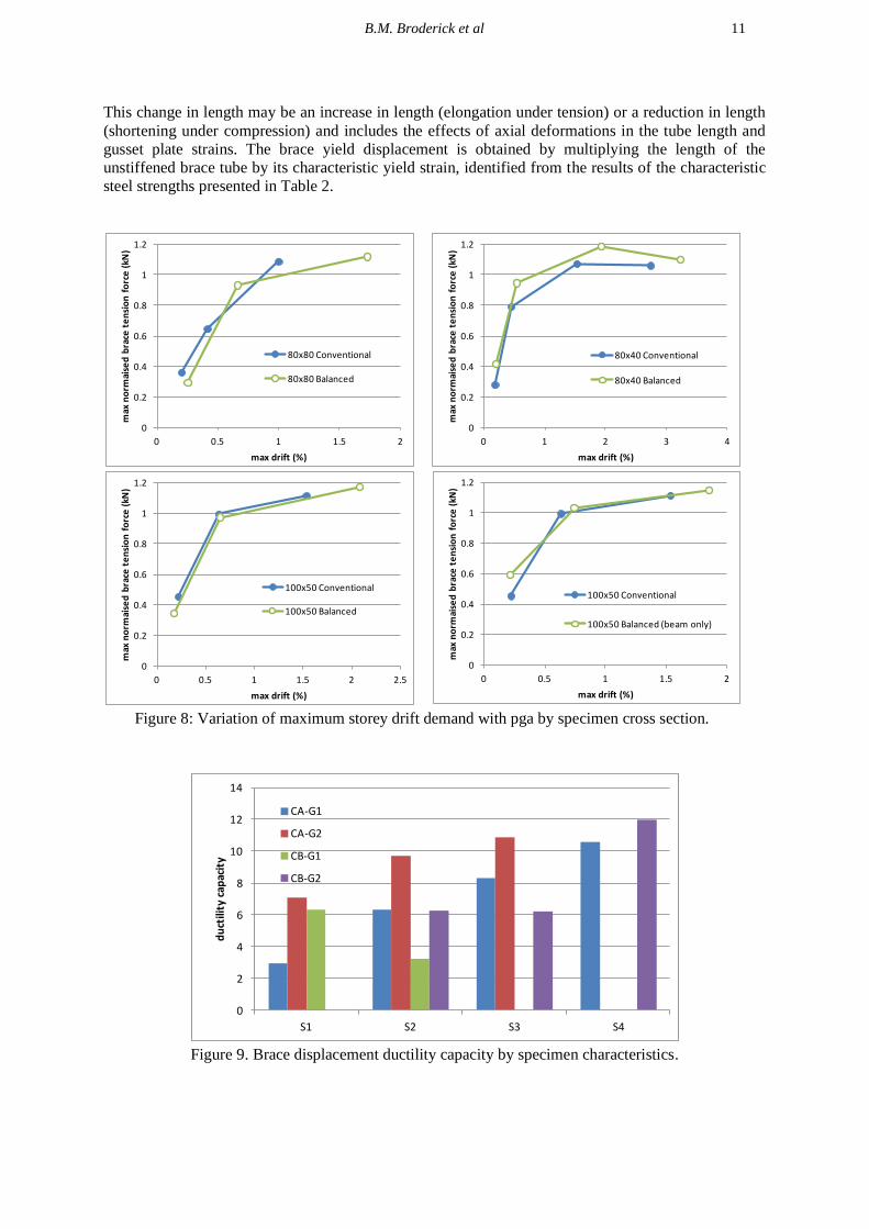
Measured maximum frame drift and brace force data can be combined to give a high-level
indication of the influence of brace-gusset plate specimen connection type on the global ductility
capacity of the test frame. The design of the experimental programme provided pairs of tests in which
the specimens differ in only one of the main test variables (brace cross-section, connection type or
gusset plate design). Figure 8 compares the response of pairs of tests which both employed the same
brace cross-section, but different connection details. The plots shown compare the variation in the
maximum normalized brace force observed in each run with the maximum drift experienced by the
test frame in that run. Three plots compare the application of the conventional and balanced design
methods to CA-type connections. In each case, the balanced design reaches a larger drift before brace
fracture. This is especially noticeable with the 80x80 specimens in which the conventional design
experienced brace fracture at a drift of only 1%. The maximum brace forces are also greater in the
balanced design cases. Overall, the comparisons presented in Figure 8 support the hypothesis that the
use of the balanced gusset plate design method leads to a more ductile and dissipative response in
CBFs without loss of brace resistance.
(a) S1 (b) S2
(c) S3 (d) S4
Figure 7: Variation of maximum storey drift demand with pga by specimen cross section.
Figure 9 presents the observed displacement ductility capacity of the brace-gusset plate specimens.
The brace ductility capacity values shown are obtained by normalizing the brace fracture elongation
by the brace yield displacement. The brace fracture elongation is the maximum measured change in
overall brace length in a fractured brace during the earthquake test run in which that brace fractured.
B.M. Broderick et al 11
This change in length may be an increase in length (elongation under tension) or a reduction in length
(shortening under compression) and includes the effects of axial deformations in the tube length and
gusset plate strains. The brace yield displacement is obtained by multiplying the length of the
unstiffened brace tube by its characteristic yield strain, identified from the results of the characteristic
steel strengths presented in Table 2.
0
0.2
0.4
0.6
0.8
1
1.2
0 0.5 1 1.5 2
max
no
rmai
sed
bra
ce t
en
sio
n f
orc
e (
kN)
max drift (%)
80x80 Conventional
80x80 Balanced
0
0.2
0.4
0.6
0.8
1
1.2
0 1 2 3 4m
ax n
orm
aise
d b
race
te
nsi
on
fo
rce
(kN
)max drift (%)
80x40 Conventional
80x40 Balanced
0
0.2
0.4
0.6
0.8
1
1.2
0 0.5 1 1.5 2 2.5
max
no
rmai
sed
bra
ce t
en
sio
n f
orc
e (
kN)
max drift (%)
100x50 Conventional
100x50 Balanced
0
0.2
0.4
0.6
0.8
1
1.2
0 0.5 1 1.5 2
max
no
rmai
sed
bra
ce t
en
sio
n f
orc
e (
kN)
max drift (%)
100x50 Conventional
100x50 Balanced (beam only)
Figure 8: Variation of maximum storey drift demand with pga by specimen cross section.
0
2
4
6
8
10
12
14
S1 S2 S3 S4
du
ctili
ty c
apac
ity
CA-G1
CA-G2
CB-G1
CB-G2
Figure 9. Brace displacement ductility capacity by specimen characteristics.
12
CONCLUSIONS
The BRACED project completed a series of shake table tests on a model CBF employing various
brace members with different cross-section and gusset plate connection details. Amongst other
properties, the test results identified the evolution of frame stiffness with drift level, the sensitivity of
frame drift to pga level, and the brace displacement ductility capacity displayed with different brace
member-gusset plate combinations. In particular, the tests confirmed that the use of a balanced design
approach in which gusset plate and brace member resistances are designed to ensure a more uniform
distribution of plastic strains can lead to higher brace ductility capacities.
The experimental results can also be used to validate and improve empirical models for the ductility
capacity of hollow section bracing members, identify active yield mechanisms and failure modes in
different brace member/connection configurations, develop and validate numerical models for
simulating the inelastic seismic response of CBFs, and provide essential data on the earthquake
response of European CBFs.
ACKNOWLEDGEMENTS
The experiments described in this paper were performed on the AZALEE shake table at the
TAMARIS Laboratory in the Laboratoire d'Etudes de Mécanique Sismique (EMSI) at CEA Saclay,
France. The scientific and professional contribution of the whole laboratory team is acknowledged.
The BRACED project was funded as transnational access activity within the FP7 SERIES project. The
support of the SERIES project selection committee is acknowledged.
REFERENCES
AISC (2005). ANSI/AISC 341-05, Seismic Provisions for Structural Steel Buildings. American
Institute of Steel Construction, Chicago, Illinois.
CEN (2004a). EN 1998-1:2004, Eurocode 8: Design of structures for earthquake resistance - Part 1:
General rules, seismic actions and rules for buildings. European Committee for Standardization,
Brussels, Belgium.
Elghazouli, A. Y. (2003). Seismic design procedures for concentrically braced frames, Structs and
Builds (2003) 156: 381-94.
Goggins, J. M., Broderick, B. M., Elghazouli, A. Y. & Lucas, A. S. (2006). Behaviour of tubular steel
members under cyclic axial loading. Journal of Constructional Steel Research, 62, 121-131
Lehman, D. E., Roeder, C. W., Herman, D., Johnson, S. & Kotulka, B. (2008). Improved Seismic
Performance of Gusset Plate Connections. Journal of Structural Engineering, 134, 890-901.
Nip, K. H., Gardner, L. & Elghazouli, A. Y. (2010). Cyclic testing and numerical modelling of carbon
steel and stainless steel tubular bracing members. Engineering Structures, 32, 424-441.
Popov, E. P. & Black, R. G. (1981). Steel struts under severe cyclic loadings. J Struct Div, ASCE
(1981)107(7):1857-81.
Roeder, C.W. (2002). Connection Performance for Seismic Design of Steel Moment Frames. Journal
of Structural Engineering, 128, 517.
Roeder, C. W. Lumpkin, E.J. and Lehman, D. E. (2011). A balanced design procedure for special
concentrically braced frame connections. Journal of Constructional Steel Research, 67, 1760-
1772.
Tremblay, R. (2002). Inelastic seismic response of steel bracing members. Journal of Constructional
Steel Research, 58, 665-701.