design requirements iterative process (drip) tool
TRANSCRIPT
Copyright retained by the authors
Presented at HILT 2016 Workshop on Model-Based Development and Contract-Based
Programming, October 2016
Design Requirements Iterative Process (DRIP) Tool Demonstration
Concurrent Engineering of Design, Requirements and Knowledge
Josef Müller
Engineered Mechatronics [email protected]
Prashanth Lakshmi Narasimhan
Engineered Mechatronics [email protected]
Swaminathan Gopalswamy
Engineered Mechatronics; Texas A&M [email protected]
Abstract
Requirements definition and design decisions are highly coupled for mechatronic systems, and heavily influenced by prior knowledge. Upfront engineering of requirements and design is of-ten addressed by inefficient, ad-hoc iterative methods. We propose a methodology to perform concurrent engineering of high level re-quirements and design along with prior knowledge by using a “common constraint framework” to describe the requirements, de-sign and knowledge precisely. Then an upfront symbolic simulta-neous analysis of all the constraints allows us to identify infeasibil-ities.
Next we define a design architecture that can be used to extend the above constraint framework to include temporal aspects leading to an ability to define low level requirements and test scenarios un-der which these requirements can be verified. Importantly the low level requirements and test scenarios can be specified independent of the final implementation. These provide the critical link between upfront requirements engineering process and downstream imple-mentation verification.
Finally we define “mappings” between implementations and the design architecture that allows definitions of executable tests in the implementation environment that in turn can be used to verify the low level requirements.
We demonstrate the above methodologies using the tool DRIP.
General Terms Algorithms, Management, Documentation, Per-formance, Design, Reliability, Experimentation, Languages, Veri-fication.
Keywords concurrent engineering of requirements and design with knowledge; iterative engineering of requirements and design with knowledge; constraint analysis framework; infeasibility anal-ysis; architecture; simulation based verification; Domain Specific Language; Projectional Editor; Language Work Bench;
1. Introduction
Cyber-physical systems (cyber systems coupled with physical sys-tems) have become ubiquitous, spanning many fields such as auto-
motive, aerospace, medical devices, and consumer devices. Conse-quently, poor performance or failure in these systems can have very large impact on the society. However, simultaneously, the com-plexity and size of these systems have also been growing exponen-tially, making analysis and verification of such systems a huge challenge. The social and economic costs of discovering faulty be-haviour of the system increases exponentially through the develop-ment process and after start of production. Many development tools and methodologies have evolved to enable discovery of such faults earlier in the development process. These tools have primarily evolved in two categories: (i) Downstream Design and Engineering (DE) tools. Examples include physical system and control system modelling tools, desktop and hardware-in-the-loop simulation tools, calibration tools, etc. and (ii) Upstream Requirements author-ing and management (RM) tools. The DE tools typically capture the behaviour of the system in machine-understandable models that are then used to drive the system development. The RM tools are focused on eliciting and documenting information in human-under-standable form, and are often not analysable. This leads to a signif-icant gap in the development process during a transition from the upstream requirements and concept definition stage to the design and implementation stage. This fundamental gap between upstream and downstream tool chains is the motivation for the development of the tool DRIP that is discussed here. Similar research initiatives are happening, example [1].
The coupling between requirements and design decisions is much stronger in cyber-physical systems compared to purely soft-ware systems. Design decisions drive requirements as much as re-quirements drive design. Complex cyber-physical systems are never built from scratch; there is a huge knowledge base that be-comes the foundation of any new development. Further this knowledge base is evolving driven by emergent requirements and design explorations. This strong linkage between requirements, de-sign and knowledge is not comprehended in today’s tool chains. Instead we rely on ad-hoc processes to iteratively engineer the re-quirements and design of a mechatronic system, while trying to map it back to a “linear V Process” through traceability linkages. These linkages become incomprehensible and minimally useful to the user as the system goes through multiple iterations. DRIP is de-veloped to address this issue, by providing a framework to concur-rently engineer requirements and design in the context of prior knowledge.
In this paper, we will describe some key methodologies that we believe are instrumental in bridging the gap between upstream and downstream engineering processes. We will illustrate an imple-mentation of these methodologies using DRIP.
2. Key Challenges to Bridging Requirements,
Design and Knowledge
2.1 Ambiguous Information
While the coupling between requirements and design rationale is relatively well-understood by practicing mechatronics engineers, there are often no systematic methods to address this because of a fundamental challenge: High Level requirements (often, even low level requirements), design rationale and prior knowledge are all documented in Natural Language (NL). NL inherently has ambigu-ity. This lack of precision leads to multiple challenges:
1. Multiple interpretations (especially when happening over space, time, people) lead to erroneous analysis.
2. Inability to identify inconsistencies in the requirements. 3. Inability to do simultaneous engineering of requirements,
design and knowledge. Instead engineers do ad-hoc iter-ations until reasonable convergence
4. Inability to “hand-off” high level requirements and de-sign rationale to downstream detailed engineering and implementation processes.
2.2 Information Overload and need for Abstraction
Sometimes knowledge is captured in precise ways through “de-tailed models” or “general purpose programming” environments. Examples include physics based simulatable models, Simulink [6] or UML based control models, excel based production schedules, Finite Element Models, C-code algorithms, etc. But each of these requires a unique set of technical expertise, that they are meaning-ful only for separate and small sets of engineers. In particular, they become somewhat irrelevant to the “systems engineer” who is try-ing to perform upstream concurrent engineering of requirements and design in the context of knowledge.
2.3 Implementation dependent definitions of test scenarios
and low level requirements
In an effort to do automated regression testing towards higher qual-ity and verification of requirements, low level requirements and test scenarios are developed in the same framework in which the imple-mentations are done. For example, if the controller is in C, tests are developed in C code in the context of the interfaces specified within the C code. Similarly if the controller is in Simulink, tests are de-veloped in the context of the Simulink model. However if the im-plementation evolves and there are changes in the interface, or if the platform of implementation changes, the tests need to be re-done. This is very time consuming and prone to human error.
3. Proposed Solution Approach
3.1 Common Constraint Framework
Our approach to providing precision is to use a common constraint framework for representing requirements. The fundamental idea of using constraints as a way to abstract information also allows us to have a framework that captures not only requirements, but also the design rationale as well as existing knowledge in a common fash-ion. For example, consider the simple case of a room heater.
1. 25 deg C <= room temperature
2. power_when_on == 500 W
3. heat_loss = 100 W/deg C * (room_temp – out-
side_temp)
The first item represents an end user requirement, the second constraint represents the constraints that are a consequence of de-sign decisions made, and the third constraint is a capture of knowledge acquired over time through testing or analysis. But all these constraints have a similar formulation, enabling a combined analysis, or concurrent engineering of requirements, design and knowledge.
The constraints are essentially a logical combination of predi-cates that are in turn created based on the behaviour of different system variables of interest. Recognizing that such precise con-straints evolve in clarity over time, we propose two layers of the constraint specification:
3.1.1 Early Stage Constraints (Invariants):
Initially we consider those constraints that can be defined to be uni-versally true, and treated as invariants. (e.g. vehicle speed shall never be greater than 300 mph; the PRNDL switch cannot be shifted to “R” when the vehicle speed is greater than 10 mph). The form of a predicate would be:
𝜙𝐼: 𝑓(𝑥, 𝑥𝐷, 𝜃) ≤ 0 (1a)
Where 𝑥 is a real variable vector of size 𝑛, 𝑥𝐷 is a enumer-
ated vector of size 𝑚 that can take on a finite set of values
and 𝜃 is vector of real parameters of size 𝑝:
𝑥 ∈ 𝑋 ⊆ ℝ𝑛 (1b) 𝑥𝐷 ∈ {𝑠1, 𝑠2, … , 𝑠𝐷}
𝑠𝑖 ∈ 𝑆 ⊆ ℝ𝑚∀𝑖 ∈ {1, 2, … , 𝐷} 𝜃 ∈ Θ ⊆ ℝ𝑝
𝑓(. , . , . ) is a piecewise continuous function in its arguments. More complex predicate constraints could be constructed using
the conjunction (AND), disjunction (OR), negation (NOT) and
implication operators.
3.1.2 Downstream Constraints (Temporal Constraints):
As the understanding and design of the system evolves, the con-straints can be more nuanced in identifying the temporal nature of the constraints. (e.g. The peak to peak vehicle acceleration shall be less than 1g within 500 ms after the PRNDL switch is shifted to “R”)
In this case, the formulation of the constraint predicates are in-spired by Signal Temporal Logic (STL). However, we do not strictly adopt STL, instead make modifications that we feel pro-vides the needed usability and expressivity.
We first extend the basic predicate to be a function of time as below, along with existence and universality qualifiers:
𝜙∀: 𝑓(𝑥(𝑡), 𝑥𝐹𝑆𝑀(𝑡), 𝜃 ) ≤ 0 ∀𝑡 ∋ {t: 𝑔(𝑥(𝑡), 𝑥𝐹𝑆𝑀(𝑡), 𝜃, 𝑡 ) ≤ 0} (2a) 𝜙∃: ∃𝑡0 ∈ {𝑡: 𝑔(𝑥(𝑡), 𝑥𝐹𝑆𝑀(𝑡), 𝜃, 𝑡 ) ≤ 0} ∋ 𝑓(𝑥(𝑡0), 𝑥𝐹𝑆𝑀(𝑡0), 𝜃 ) ≤ 0 (2b)
Here 𝑥 is a time-dependent vector, and is in fact associated with the behaviour of a system that is defined in the form of an architec-ture (defined later below in 3.4 ). 𝑥𝐹𝑆𝑀 is a vector state of a finite state machine with vector-length 𝑚, also defined in the context of an architecture. 𝑡 represents time.
As with the invariant constraints, more complex predicate con-straints could be constructed using the conjunction (AND), disjunc-tion (OR), negation (NOT) and implication operators.
The above mathematical representation of the constraints, both in the simpler invariant form and in the temporal constraint form, are sufficient to cover a large range of requirements, design and knowledge relevant for mechatronics system development.
Specifically, the invariant constraints are directly used for per-forming solution infeasibility analysis, and the temporal constraints are used for performing simulation based requirement verification analysis.
3.2 Multi-Notation Representation
While the common constraint framework above is powerful in providing the mechanism for analysis, its biggest drawback comes from the fact that it is too mathematical to be of interest to a large number of practicing engineers – both in terms of understanding as well as usability. We address this in DRIP explicitly through the use of technologies (see section 4.2 for specific enabling technologies) that facilitate multiple representations of the same object. Every concept within DRIP is captured by an explicit “model” of the concept, which can then be “projected” through multiple editors, providing multiple user-experiences for the end user. In particular, the constraints are concepts that can be projected either as mathematical expressions, or can be projected as text that provides the same meaning, but is more readable. In this paper we refer to this projection as “Con-trolled Natural Language” (CNL).
3.3 Upfront (In)Feasibility Analysis
A fundamental question that needs to be addressed when the re-quirements are considered in the context of some design choices and existing prior knowledge is: Is the solution set for the system consisting of the requirements, design and knowledge feasible? This is a question that is difficult to answer precisely at early stages of the system development. However, the following reverse ques-tion could be posed: Is the solution set for the system consisting of the requirements, design and knowledge “infeasible”? This is in fact a solvable problem for the case of Invariants in equations (1).
DRIP will perform the mathematical analysis to identify the do-mains {𝑋, 𝑆, Θ} that satisfies equations (1). If 𝑋 = { }, 𝑆 = { } or Θ = { } is true, then we declare the problem infeasible.
As we concurrently consider the requirements, design and prior knowledge we avoid having to iterate to find a solution.
An important by-product of such an analysis is the identification of the available design space Θ, as this can be useful in understand-ing the robustness of the final solution, as well as enhance any downstream optimization performed over the design space.
3.4 Design Architecture, LLRs and Test Scenarios
3.4.1 Design Architecture
In order to meaningfully tie the upstream high level requirements and design engineering efforts into the downstream more detailed design and implementation, we use the concept of the Design Ar-chitecture (DA). The DA is intended to be a high level representa-tion of the system, that is independent of the implementation; how-ever it has enough richness to enable precise specification of the low level requirements for the system, as well as the test scenarios that shall be used to verify that the system satisfies the require-ments.
The DA consists of the definition of the topology of the system – in terms of the hierarchical decomposition of the system, the in-terfaces, and the connectivity. The DA can also specify high level state behaviour through finite state machine definitions. The DA can also specify stimulating actions on the architecture.
3.4.2 Low Level Requirement (LLR)
Once a DA is defined, low level requirements can be defined for that DA. To do this, we use the temporal constraints as in equations
(2), with the vectors 𝑥 and 𝑥𝐹𝑆𝑀 directly associated with the DA. The use of the constraints enables the LLR to be analysed.
3.4.3 Test Scenario
A Test Scenario (TS) is also defined for a specific DA. A TS is defined as a sequence of steps to be taken by one or more actors, during which the LLRs associated with the DA will be evaluated for conformance. Appropriate methods to define transitions be-tween steps, including going back to previous steps (loops) are pro-vided for within DRIP. Essentially, DRIP has a language to define the TS precisely, and thus the TS can be used in downstream anal-ysis.
3.5 Simulation Based Verification of Implementation
3.5.1 Mapping an Implementation to Design Architecture
An important consideration within DRIP is the idea of an “up-stream” definition of the design, independent of the implementa-tion. This translates to definitions of a Design Architecture that is independent of the implementation, and definitions of Require-ments and Test Scenarios, all tied to the DA, but independent of the implementation. This is described in section 3.4 above. However, when an implementation needs to be verified against the require-ments, we need a mechanism to connect the Design Architecture with the Implementation.
This is done in DRIP through the idea of “Architecture Map-ping”. (AM). First, we extract an “Implementation Architecture (IA) from the implementation. This will include critical infor-mation such as the interfaces, the stimulating functions, parameters, important internal signals, etc. Then we define a language within DRIP to associate individual elements of the IA to the elements of the DA. This association is the AM.
When there are multiple implementations for a given design ar-chitecture, we simply create multiple AMs, one each for every im-plementation.
3.5.2 Verification Test Definition
Once we have an AM defined, we can define the tests to be per-formed:
A Test is defined for an Implementation model, for a specific AM. This is then interpreted as executing the Implementation model, for specific test scenarios that are defined for the Design Architecture corresponding to the AM. During such execution, all the requirements defined for the Design Architecture shall be veri-fied for conformance.
Within DRIP a special language is built to describe the Test Definitions.
3.5.3 Simulation Based Verification
The final step in the verification process is actual execution of the Test. DRIP currently provides an interface with Simulink, so implementations in Simulink can be tested automatically from DRIP. A Test Harness is automatically created in Simulink around the original simulation. The Test Harness includes the auto-gener-ated test scenarios and verification criteria.
When the Test Harness is simulated, the requirements are as-sessed for any violations. The results of the simulation are then re-verted back to DRIP for recording and display of successful verifi-cation or failure.
In order to do a thorough verification we would need multiple test scenarios, and specialized analysis to understand the coverage of the test scenarios in the context of the degrees of freedom for the
system. However such analysis is beyond the scope of DRIP cur-rently and so will not be discussed here.
4. Enabling Technologies
4.1 Domain Specific Languages and Language Workbenches
One of the fundamental challenges that we set out to address is the balance between ambiguous information when using NL to express information, and information overload and lack of usability when using detailed modelling or general purpose programming lan-guages.
Our solution hinges on identifying key concepts that are rele-vant to the systems engineer – concepts that help bridge the up-stream requirements/design engineering process and the down-stream design and implementation processes. These concepts then need to be precisely defined, and evolved in to a “custom language” that is not only meaningful to the practicing engineer, but also ma-chine readable and analysable by a computer.
While function interfaces and scripting mechanisms provide one way to develop such a language, we decided to formalize this approach leveraging the many advances made in “Domain Specific Languages” [2]. Specifically we have paid attention to making these custom languages not ad-hoc constructs, but a set of con-structs that have well defined semantics, type definitions and rules, clear relationships and constraints with respect to other concepts, etc.
These languages essentially allow every aspect of the processes supported by DRIP to be “modelled” explicitly. The concepts are all relatable to each other, and thus enables the paradigm that we call “Extreme Model Based Development” (XMBD) [3]. Such an XMBD approach is critically important as we link information across the development processes. For example, having a common variable definition that is used in the upfront analysis as also down-stream as part of the simulation based verification.
The value of a DSL is ultimately defined by the end-user expe-rience when performing operations such as creating, editing, searching, re-factoring, etc. From an implementation development perspective, this can often be very time consuming and expensive, without any unique value-add. However, this effort is dramatically reduced by leveraging “Language Workbenches” which allow the developer to define the language concepts at a high level of abstrac-tion, and auto-generate the user-experience aspects with relatively little effort. The Language Workbench that is leveraged for the de-velopment of DRIP is MPS [4].
Well defined DSLs have the advantage that concepts can be cu-mulatively integrated, enabling significant leverage of prior work. DRIP is also built by leveraging the large volume of work already done developing useful DSLs as part of the mbeddr project [5].
4.2 Projectional Editing based Language Workbench
Another fundamental challenge that we wanted to address was to provide a more user-friendly experience in defining the con-straints of the common constraint framework. The precise way of describing the constraints is important from the point of view of analysis – both the upfront infeasibility analysis using symbolic computer algebra, as well as the downstream verification analysis using simulation of the implementations. However, this mathemat-ical notation of the constraints is tailored for mathematicians and control theoretic engineers, and is often unnatural for many prac-ticing engineers. In DRIP we wanted to provide alternate user ex-periences. Specifically, we provide “Controlled Natural Language” (CNL) expressions for the mathematical constraints, that are simi-lar to NL, however retain the precision of the underlying mathe-matical constraints. This is achieved by maintaining the constraints
using the structure of the underlying model of the constraints (as an Abstract Syntax Tree), but using different “projections” to provide different user experiences when viewing or editing the constraints. Language Editors that support such multiple projections of a com-mon concept are called “Projectional Editors”, and MPS is a prime example of projectional editing technology.
5. Illustration of methodology with DRIP
We will illustrate the above concepts by applying the tool DRIP on a safety-critical application.
5.1 Collision Warning System (CWS)
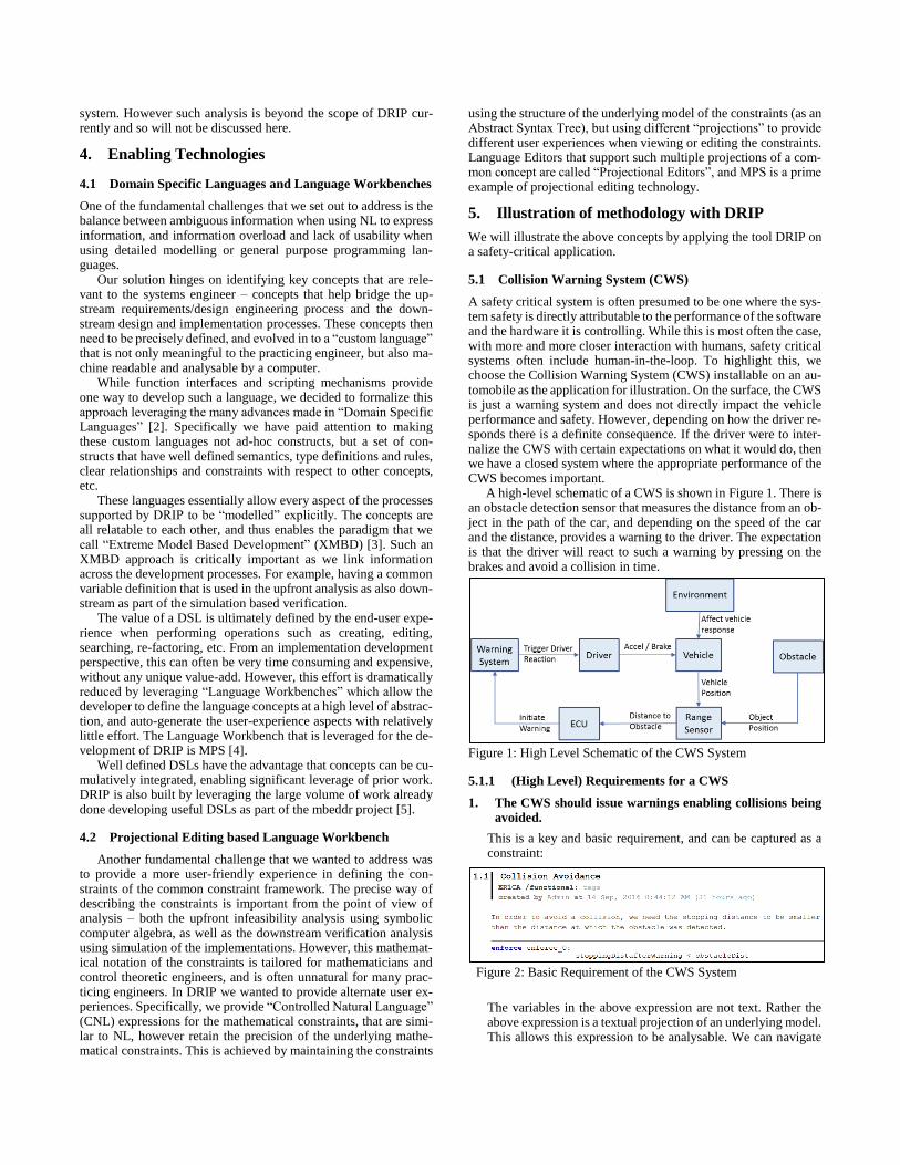
A safety critical system is often presumed to be one where the sys-tem safety is directly attributable to the performance of the software and the hardware it is controlling. While this is most often the case, with more and more closer interaction with humans, safety critical systems often include human-in-the-loop. To highlight this, we choose the Collision Warning System (CWS) installable on an au-tomobile as the application for illustration. On the surface, the CWS is just a warning system and does not directly impact the vehicle performance and safety. However, depending on how the driver re-sponds there is a definite consequence. If the driver were to inter-nalize the CWS with certain expectations on what it would do, then we have a closed system where the appropriate performance of the CWS becomes important.
A high-level schematic of a CWS is shown in Figure 1. There is an obstacle detection sensor that measures the distance from an ob-ject in the path of the car, and depending on the speed of the car and the distance, provides a warning to the driver. The expectation is that the driver will react to such a warning by pressing on the brakes and avoid a collision in time.
Figure 1: High Level Schematic of the CWS System
5.1.1 (High Level) Requirements for a CWS
1. The CWS should issue warnings enabling collisions being
avoided.
This is a key and basic requirement, and can be captured as a constraint:
The variables in the above expression are not text. Rather the above expression is a textual projection of an underlying model. This allows this expression to be analysable. We can navigate
Figure 2: Basic Requirement of the CWS System
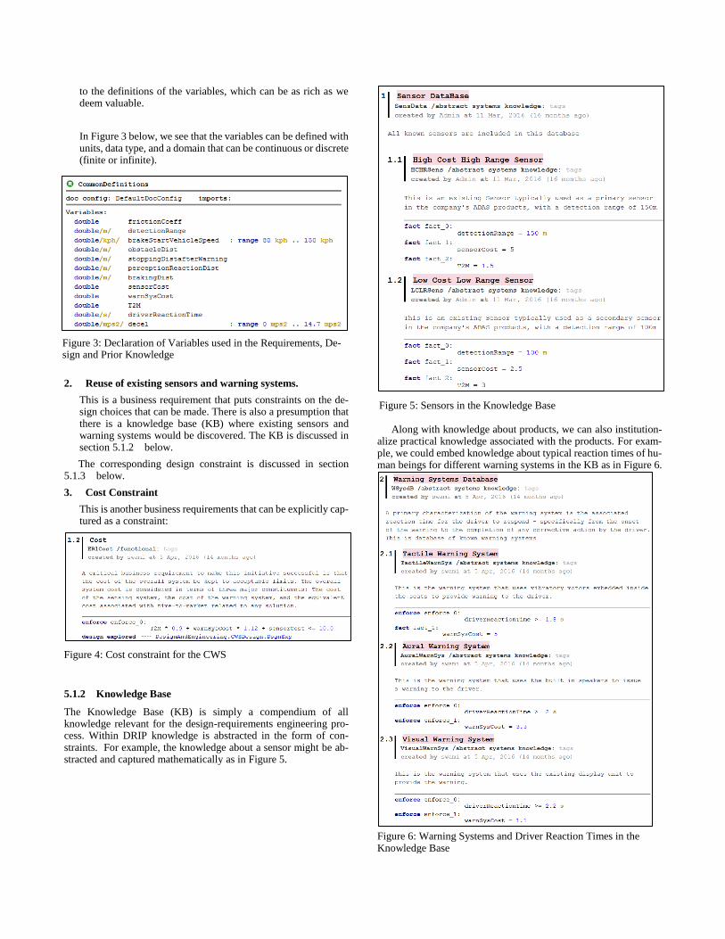
to the definitions of the variables, which can be as rich as we deem valuable.
In Figure 3 below, we see that the variables can be defined with units, data type, and a domain that can be continuous or discrete (finite or infinite).
2. Reuse of existing sensors and warning systems.
This is a business requirement that puts constraints on the de-sign choices that can be made. There is also a presumption that there is a knowledge base (KB) where existing sensors and warning systems would be discovered. The KB is discussed in section 5.1.2 below.
The corresponding design constraint is discussed in section 5.1.3 below.
3. Cost Constraint
This is another business requirements that can be explicitly cap-tured as a constraint:
5.1.2 Knowledge Base
The Knowledge Base (KB) is simply a compendium of all knowledge relevant for the design-requirements engineering pro-cess. Within DRIP knowledge is abstracted in the form of con-straints. For example, the knowledge about a sensor might be ab-stracted and captured mathematically as in Figure 5.
Along with knowledge about products, we can also institution-
alize practical knowledge associated with the products. For exam-ple, we could embed knowledge about typical reaction times of hu-man beings for different warning systems in the KB as in Figure 6.
Figure 3: Declaration of Variables used in the Requirements, De-sign and Prior Knowledge
Figure 4: Cost constraint for the CWS
Figure 5: Sensors in the Knowledge Base
Figure 6: Warning Systems and Driver Reaction Times in the Knowledge Base
Further, constraints arising from laws of Physics are captured
inside the Knowledge Base.
5.1.3 Initial Design Constraints
The Design constraints are derived from the requirement to reuse sensors and warning systems. This is captured in Figure 8 below:
Combining the design constraint with the KB, we can conclude
that there are two choices for the sensors (high cost and low cost sensor) and three choices for the warning system (aural, tactile and visual).
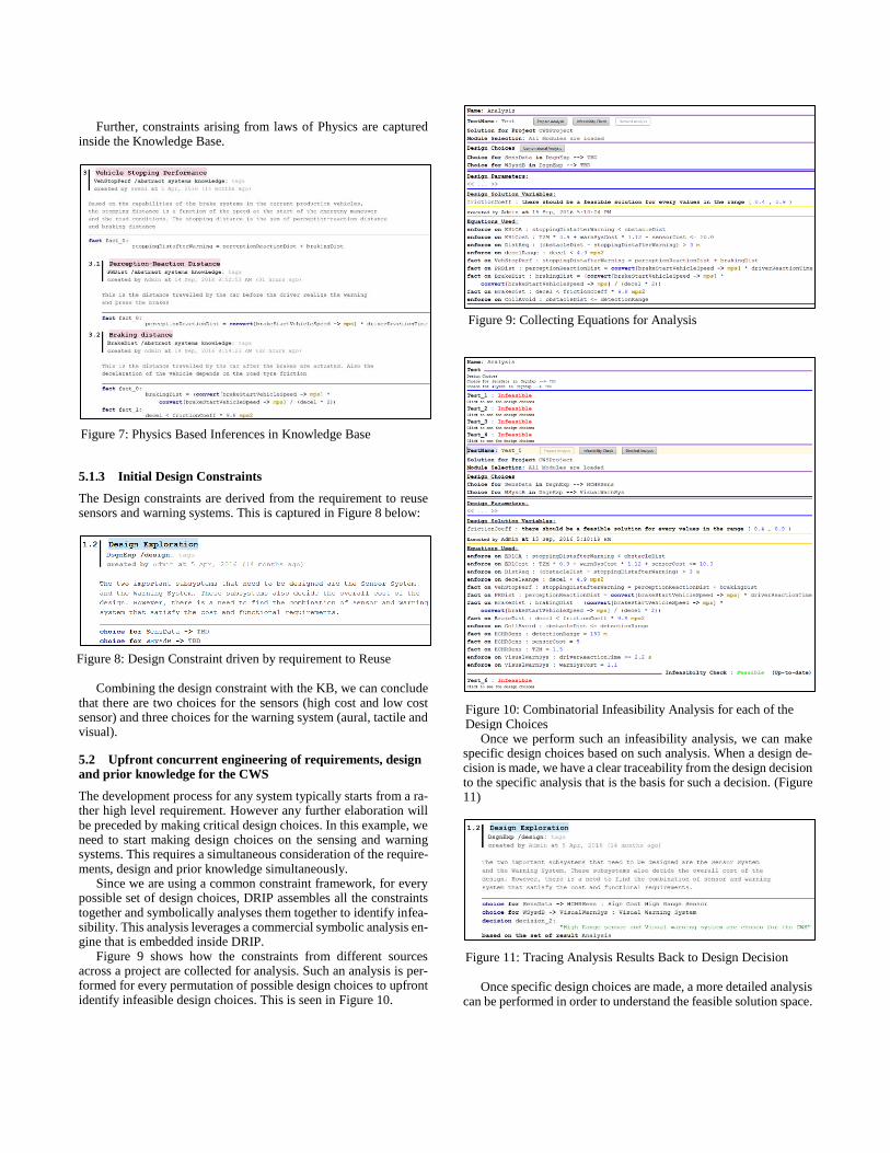
5.2 Upfront concurrent engineering of requirements, design and prior knowledge for the CWS
The development process for any system typically starts from a ra-ther high level requirement. However any further elaboration will be preceded by making critical design choices. In this example, we need to start making design choices on the sensing and warning systems. This requires a simultaneous consideration of the require-ments, design and prior knowledge simultaneously.
Since we are using a common constraint framework, for every possible set of design choices, DRIP assembles all the constraints together and symbolically analyses them together to identify infea-sibility. This analysis leverages a commercial symbolic analysis en-gine that is embedded inside DRIP.
Figure 9 shows how the constraints from different sources across a project are collected for analysis. Such an analysis is per-formed for every permutation of possible design choices to upfront identify infeasible design choices. This is seen in Figure 10.
Once we perform such an infeasibility analysis, we can make specific design choices based on such analysis. When a design de-cision is made, we have a clear traceability from the design decision to the specific analysis that is the basis for such a decision. (Figure 11)
Once specific design choices are made, a more detailed analysis
can be performed in order to understand the feasible solution space.
Figure 7: Physics Based Inferences in Knowledge Base
Figure 8: Design Constraint driven by requirement to Reuse
Figure 9: Collecting Equations for Analysis
Figure 10: Combinatorial Infeasibility Analysis for each of the Design Choices
Figure 11: Tracing Analysis Results Back to Design Decision
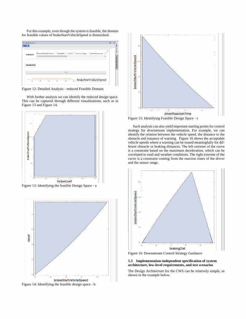
For this example, even though the system is feasible, the domain for feasible values of brakeStartVehicleSpeed is diminished.
Figure 12: Detailed Analysis - reduced Feasible Domain
With further analysis we can identify the reduced design space.
This can be captured through different visualizations, such as in Figure 13 and Figure 14.
Figure 13: Identifying the feasible Design Space - a
Figure 14: Identifying the feasible design space - b
Figure 15: Identifying Feasible Design Space - c
Such analysis can also yield important starting points for control
strategy for downstream implementation. For example, we can identify the relation between the vehicle speed, the distance to the obstacle and issuance of warning. Figure 16 shows the acceptable vehicle speeds where a warning can be issued meaningfully for dif-ferent obstacle or braking distances. The left extreme of the curve is a constraint based on the maximum deceleration, which can be correlated to road and weather conditions. The right extreme of the curve is a constraint coming from the reaction times of the driver and the sensor range.
Figure 16: Downstream Control Strategy Guidance
5.3 Implementation-independent specification of system
architecture, low-level requirements, and test scenarios
The Design Architecture for the CWS can be relatively simple, as shown in the example below.
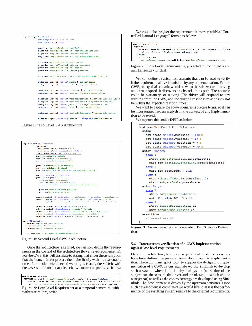
Once the architecture is defined, we can now define the require-
ments in the context of the architecture (lower level requirements). For the CWS, this will translate to stating that under the assumption that the human driver presses the brake firmly within a reasonable time after an obstacle-detected warning is issued, the vehicle with the CWS should not hit an obstacle. We make this precise as below:
We could also project the requirement in more readable “Con-trolled Natural Language” format as below:
We can define a typical test scenario that can be used to verify
if the requirement above is satisfied by any implementation. For the CWS, one typical scenario would be when the subject car is moving at a certain speed, it discovers an obstacle in its path. The obstacle could be stationary, or moving. The driver will respond to any warning from the CWS, and the driver’s response may or may not be within the expected reaction times.
We want to capture the above scenario is precise terms, so it can be incorporated into an analysis in the context of any implementa-tion to be tested.
We capture this inside DRIP as below:
Figure 21: An implementation-independent Test Scenario Defini-tion
5.4 Downstream verification of a CWS implementation against low level requirements
Once the architecture, low level requirements and test scenarios have been defined the process moves downstream to implementa-tion. There are many great tools to support the design and imple-mentation of a CWS. In our example we use Simulink to develop such a system, where both the physical system (consisting of the subject car, the sensors, the driver and the obstacle – which will be a target car) as well as the control strategy are developed using Sim-ulink. The development is driven by the upstream activities. Once such development is completed we would like to assess the perfor-mance of the resulting system relative to the original requirements.
Figure 17: Top Level CWS Architecture
Figure 18: Second Level CWS Architecture
Figure 19: Low Level Requirement as a temporal constraint, with mathematical projection
Figure 20: Low Level Requirements, projected in Controlled Nat-ural Language - English
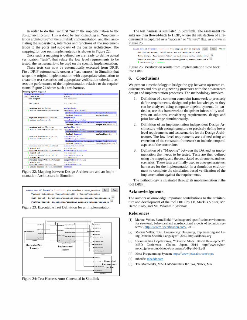
In order to do this, we first “map” the implementation to the design architecture. This is done by first extracting an “implemen-tation architecture” of the Simulink implementation, and then asso-ciating the subsystems, interfaces and functions of the implemen-tation to the ports and sub-parts of the design architecture. The mapping for one such implementation is shown in Figure 22.
Once such a mapping is defined we are ready to define actual verification “tests”, that relate the low level requirements to be tested, the test scenario to be used on the specific implementation.
These tests can now be automatically executed from DRIP. First, DRIP automatically creates a “test harness” in Simulink that wraps the original implementation with appropriate stimulation to create the test scenarios and appropriate verification criteria to as-sess the performance of the implementation relative to the require-ments. Figure 24 shows such a test harness.
Figure 22: Mapping between Design Architecture and an Imple-mentation Architecture in Simulink
Figure 23: Executable Test Definition for an Implementation
Figure 24: Test Harness Auto-Generated in Simulink
The test harness is simulated in Simulink. The assessment re-sults are then flowed-back to DRIP, where the satisfaction of a re-quirement is captured as a “success” or “failure” flag, as shown in Figure 25.
Figure 25: Verification results from Implementation flow back into DRIP
6. Conclusions
We present a methodology to bridge the gap between upstream re-quirements and design engineering processes with the downstream design and implementation processes. The methodology involves
1. Definition of a common constraint framework to precisely define requirements, design and prior knowledge, so they can be analysed using computer algebra systems. In par-ticular, use this framework to do upfront infeasibility anal-ysis on solutions, considering requirements, design and prior knowledge simultaneously.
2. Definition of an implementation independent Design Ar-chitecture with enough structure to precisely define lower level requirements and test scenarios for the Design Archi-tecture. The low level requirements are defined using an extension of the constraint framework to include temporal aspects of the constraints.
3. Definition of a “Mapping” between the DA and an imple-mentation that needs to be tested. Tests are then defined using the mapping and the associated requirements and test scenarios. These tests are finally used to auto-generate test harnesses for the implementation in a simulation environ-ment to complete the simulation based verification of the implementation against the requirements.
The methodology is illustrated through its implementation in the tool DRIP.
Acknowledgments
The authors acknowledge important contributions to the architec-ture and development of the tool DRIP by Dr. Markus Völter, Mr. Bernd Kolb, and Mr. Wladimir Safonov.
References
[1] Markus Völter, Bernd Kold, “An integrated specification environment for structural, behavioral and non-functional aspects of technical sys-tems”, http://system-specification.com/, 2015.
[2] Markus Völter, “DSL Engineering: Designing, Implementing and Us-ing Domain-Specific Languages”, 2013, http://dslbook.org
[3] Swaminathan Gopalswamy, “eXtreme Model Based Development”, MBD Conference, Chubu, Japan, 2014 http://www.cyber-net.co.jp/event/mbdchubu/documents/pdf/pmb3-2.pdf
[4] Meta Programming System: https://www.jetbrains.com/mps/
[5] mbeddr: mbeddr.com
[6] The Mathworks, MATLAB/Simulink R2014a, Natick, MA