design rules for avoiding draw horizon damage in deep ... · induce the caving process; in the case...
TRANSCRIPT

▲151The Journal of The South African Institute of Mining and Metallurgy MAY/JUNE 1999
Introduction
Block caving is described by Laubscher (1994)as the lowest cost underground mining methodprovided that the extraction layout is designedto suit the caved material and the drawhorizon can be maintained for the life of thedraw. An examination of this statement showsthat not only is correct size and spacing of thedraw points essential for efficient extraction,but also that stability of the draw horizon overthe full life of draw is essential for the successof the block caving operation. This need forstability is further emphasised by therealization that, due to draw requirements,block cave layouts are relatively inflexiblewhen compared with systems to extracttabular ore bodies. The importance of stabilityin draw horizons is further highlighted by thelong life of the draw level compared to tabularmining methods. In essence the average blockcave has a life expectancy of 5-20 yearscompared with, for example, a scatteredmining stope in a tabular gold mine which hasa life expectancy of 2 years. If stabilityproblems occur, they are not easily remediedand normally have a severe impact onproduction. Laubscher (1994) identified 25parameters that should be considered beforethe implementation of any cave miningoperation. This paper draws from Laubscher’spaper and presents five rules which, if properlyimplemented, will ensure that draw horizonstability is maintained. Slusher and tracklessblock caving mining methods and the threats
to the draw horizon in these operations aredescribed.
Mining methods
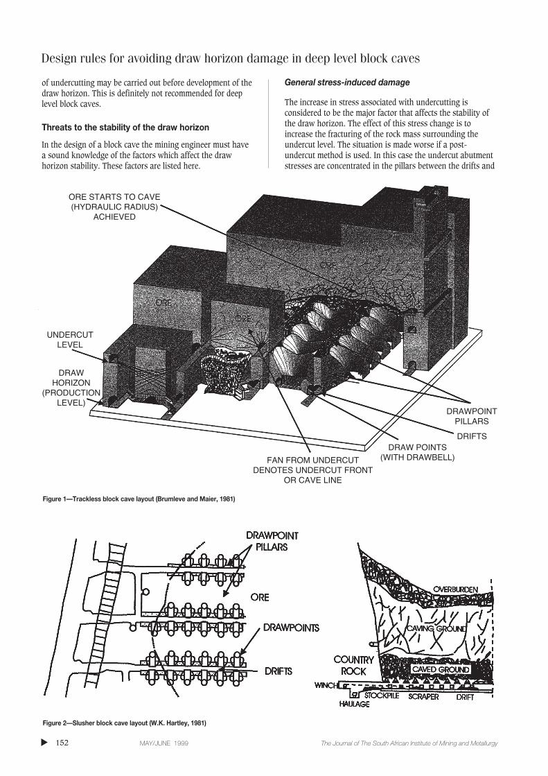
Typical layouts for trackless and slusher blockcaving systems are described by Owen andGuest (1994) and Hartley (1981) and areshown in Figures 1 and 2. The essentialfeatures of block caving systems are:
➤ a draw horizon or production levelwhere the caved ore will be extractedthrough draw points;
➤ an undercut level whose function is tocreate a void above the draw horizon toinduce the caving process;
➤ in the case of a deep-level block cavetwo undercutting development methodsmay be used, namely:
Block cave development using a post-undercut method. In this system accesstunnels and haulages are developed from theshaft to the contact of the ore bodies. The drawhorizon is then developed complete with drawpoints. The block is then brought intoproduction by advancing the undercut front(cave line) over the draw horizon. Theundercutting can be done from a separate levelabove the draw horizon or from the drawpoints.
Block cave development using an advancedundercut system. In this system the countryrock development is advanced to the ore bodyand the undercut front is advanced before thedraw horizon has been developed. The drawhorizon and draw points are then developed indestressed conditions. The use of this systemnormally requires the development of aseparate undercut level. The advancedundercut system should not be confused witha pre-undercut system in which a large extent
Design rules for avoiding draw horizondamage in deep level block cavesby R.J. Butcher*
Synopsis
Deep level block caving as a mining method is becoming morepopular due to the fact that it is the lowest cost per tonunderground extraction system. However, many block caves do notachieve their full potential due to draw horizon instability. In thispaper five design rules are given to overcome this problem. Thedesign rules described are applicable for slusher and trackless blockcaves where the operational depths exceed 500 metres.
* Steffen, Robertson and Kirsten, Johannesburg,South Africa.
© The South African Institute of Mining andMetallurgy, 1999. SA ISSN 0038–223X/3.00 +0.00. Paper received May. 1998; revised paperreceived Aug. 1998.
Design rules for avoiding draw horizon damage in deep level block caves
of undercutting may be carried out before development of thedraw horizon. This is definitely not recommended for deeplevel block caves.
Threats to the stability of the draw horizon
In the design of a block cave the mining engineer must havea sound knowledge of the factors which affect the drawhorizon stability. These factors are listed here.
General stress-induced damage
The increase in stress associated with undercutting isconsidered to be the major factor that affects the stability ofthe draw horizon. The effect of this stress change is toincrease the fracturing of the rock mass surrounding theundercut level. The situation is made worse if a post-undercut method is used. In this case the undercut abutmentstresses are concentrated in the pillars between the drifts and
▲
152 MAY/JUNE 1999 The Journal of The South African Institute of Mining and Metallurgy
Figure 1—Trackless block cave layout (Brumleve and Maier, 1981)
Figure 2—Slusher block cave layout (W.K. Hartley, 1981)
ORE STARTS TO CAVE(HYDRAULIC RADIUS)
ACHIEVED
UNDERCUTLEVEL
FAN FROM UNDERCUTDENOTES UNDERCUT FRONT
OR CAVE LINE
DRAW POINTS(WITH DRAWBELL)
DRIFTS
DRAWPOINTPILLARS
DRAWHORIZON
(PRODUCTIONLEVEL)

draw points, resulting in possible scaling and failure of thepillars and drift damage. The drifts can be further damagedby the relaxation of the fractured rockmass which occursafter undercutting. The magnitude of this damage is normallyproportional to the depth below surface, the undercut height,the distance between the undercut and the draw horizon, thestrength of the rock mass, and the pillar size. It has beenfound that where draw horizon development accounts formore than 60% of the level (i.e. only 40% of the area is leftas pillars) stress-induced damage becomes unmanageable. Inthe case where in excess of 80% of the draw horizon isdeveloped such as in the case of a slusher block cave, thepost-undercutting induced stresses can result in severedamage and the collapse of this level. It is questionablewhether the post-undercut method is suitable for slusherblock cave development below depths of 500 metres. Itshould be noted that the magnitude of damage is increased ifdrawpoint and drift development is left unsupported for aconsiderable period. Under such conditions the collapse ofthe draw horizon may occur during undercutting.
Stress concentration due to large irregularities in thehorizontal configuration of the undercut front(cave line)
Large irregularities in the horizontal configuration of theundercut front (cave line) cause an increase in stress concen-tration, which may result in serious damage. An illustrationof this concept is given in Figure 3. The lagging zone will besubjected to significantly increased stresses.
Stress-induced damage due to slow undercut rates ofadvance
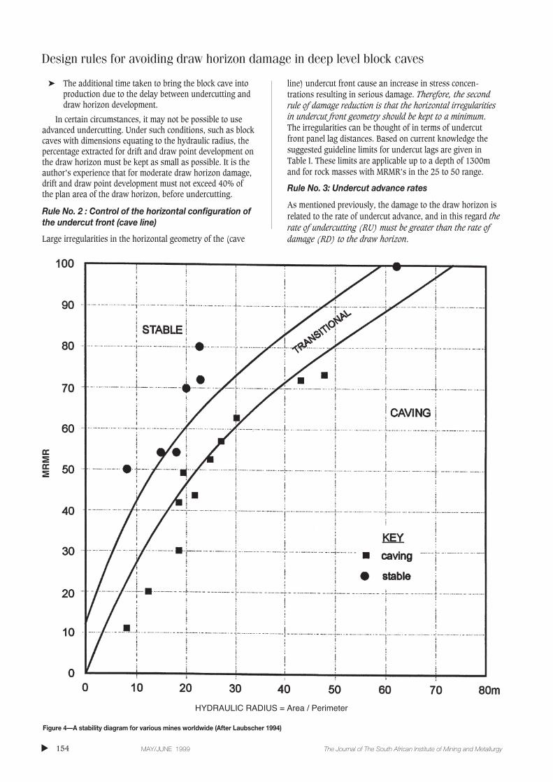
The speed of the undercut is an important factor in themagnitude of stress-induced damage to the draw horizon.Stress-induced damage increases with a reduction in the rateof advance of the undercut front (cave line). The undercutabutment stresses reach the maximum magnitude when theundercut area equates to the required hydraulic radius of theblock. It should be noted that stress-induced damage starts toincrease once the undercut area equates to half the requiredhydraulic radius of the block. The concept of determiningcavability by using the mining rock mass rating system andthe hydraulic radius (Laubscher, 1994) is given in Figure 4.
Undercut front arch-induced crushing due to the non-propagation of the cave
As the undercut starts to advance an arch is formed abovethis area. The span of the arch increases until caving isachieved at hydraulic radius. At this point caving of the orebody will naturally continue to propagate if drawingcommences. As drawing commences there is a reduction inundercut front stresses. However, if an area equating tohydraulic radius has been undercut but drawing does notcommence and the undercut continues to advance, theundercut front stresses increase with increases in the span ofthe arch until crushing of the undercut front occurs. From theauthor’s experience with caves in diamond mines, thisnormally occurs when the undercut advances about 45metres linearly across the block from hydraulic radiusposition.
Design rules
Taking cognisance of the listed threats the following areempirical design rules which, when implemented, can reduceor eliminate damage to the draw horizon.
Rule No. 1: Block cave advanced undercutting
Considering the fact that post undercutting results in thestress-induced damage to the draw horizon level it would beprudent that the undercut should be advanced first and thedraw horizon should be developed in de-stressed conditions.Therefor, the first rule of draw horizon damage reduction isthat advanced undercutting of the block cave should takeplace. However, the use of advanced undercutting has thefollowing disadvantages:
➤ Increased capital cost due to the fact that an additionallevel is required
➤ Sequence problems because draw horizon developmentmust follow closely behind the undercut to avoid theregeneration of undercut stresses due to undercutmuck pile compaction. In the author’s experience thetime lag between undercutting and draw horizondevelopment should not exceed 6 months.
Design rules for avoiding draw horizon damage in deep level block caves
▲153The Journal of The South African Institute of Mining and Metallurgy MAY/JUNE 1999
Figure 3—Cave line geometries in plan
UNDERCUT AREA
CAVE LINE
CAVE LINE
IDEAL CONTROL
ACCEPTABLE CONTROL
‘SMALL IRREGULARITIES’
‘CAVE LINE LAG’
POORCONTROL‘LARGEIRREGULARITIES,
‘CAVE LINELEAD’
CAVE LINE
RETREAT DIRECTION
RETREAT DIRECTION
RETREAT DIRECTION
UNDERCUT AREA
UNDERCUT AREA
Design rules for avoiding draw horizon damage in deep level block caves
➤ The additional time taken to bring the block cave intoproduction due to the delay between undercutting anddraw horizon development.
In certain circumstances, it may not be possible to useadvanced undercutting. Under such conditions, such as blockcaves with dimensions equating to the hydraulic radius, thepercentage extracted for drift and draw point development onthe draw horizon must be kept as small as possible. It is theauthor’s experience that for moderate draw horizon damage,drift and draw point development must not exceed 40% ofthe plan area of the draw horizon, before undercutting.
Rule No. 2 : Control of the horizontal configuration ofthe undercut front (cave line)
Large irregularities in the horizontal geometry of the (cave
line) undercut front cause an increase in stress concen-trations resulting in serious damage. Therefore, the secondrule of damage reduction is that the horizontal irregularitiesin undercut front geometry should be kept to a minimum.The irregularities can be thought of in terms of undercutfront panel lag distances. Based on current knowledge thesuggested guideline limits for undercut lags are given inTable I. These limits are applicable up to a depth of 1300mand for rock masses with MRMR’s in the 25 to 50 range.
Rule No. 3: Undercut advance rates
As mentioned previously, the damage to the draw horizon isrelated to the rate of undercut advance, and in this regard therate of undercutting (RU) must be greater than the rate ofdamage (RD) to the draw horizon.
▲
154 MAY/JUNE 1999 The Journal of The South African Institute of Mining and Metallurgy
Figure 4—A stability diagram for various mines worldwide (After Laubscher 1994)
MR
MR
HYDRAULIC RADIUS = Area / Perimeter

RU > RD
However, after the block cave has been undercut to anarea equivalent to its required hydraulic radius, it isimportant that the rate of undercutting is never greater thanthe rate of caving (RC). This is in order to prevent theformation of an arch above the undercut face which couldlead to undercut front (caveline) crushing, which in turncould allow the propagation of the cave to occur. In thisregard the following rule should apply after the block cave’shydraulic radius has been achieved (Laubscher, 1994).
RC > RU > RD
It is the author’s experience that undercut advance ratesin the region of 1100m2 per month are sufficient to preventsevere damage. It should be noted that these advance rateswere obtained from experience with post undercut slushercave at depths in excess of 500 metres. As a general rule thesmaller the undercut height the faster the undercut rate, dueto the fact that less drilling and charging is required than forthe larger undercuts. The undercut height should be as smallas possible, and it is the author’s experience that undercutheights of 1.5m can suffice. However, in practice, minimumundercut heights tend to be in the region of the height of theundercut development.
Rule No. 4: Elevation of the undercut
The height of the undercut above the base of the drawhorizon varies from mine to mine. However, since thedamage effects from undercut front (cave line) stressesdecrease with an increase in vertical distance between the
draw and undercut horizons, the fourth rule of damagereduction should be that the undercut horizon should beplaced as high as practically possible above the drawhorizon. It is the author’s experience that the most practicaldistance between the undercut and draw horizon levels, interms of draw control, stress and induced damage reduction,and hang up access, is in the region of 15 metres.
Rule No. 5 : Cave propagation to eliminate undercutfront arch-induced crushing
A further consideration in reducing the magnitude ofundercut stresses is to ensure that the undercut reaches thehydraulic radius position as quickly as possible. This isnecessary to ensure that cave propagation can occur with theeffect of reducing the magnitude of undercut abutmentstresses. Since caving is affected not only by the undercutdimensions but also by the rock mass strength, the fifth ruleof block caving is that the undercut front must advance fromthe weakest ground to the strongest ground thus ensuringthat cave propagation occurs as quickly as possible. Anadditional benefit of the application of this rule is that finalportions of the block to be undercut are always situated inthe strongest ground, thus reducing the magnitude of stress-induced damage further.
The above rules have been determined by experiencegained on deep level block caves. It is believed that theapplication of these empirical design rules will provide thebasis for avoiding stress-induced damage to deep level blockcaves, thus ensuring that planned block caves achieve theirfull production potential.
References
BRUMLEVE, C.B. and MAIER, M.M. Applied investigations of rock mass response
to panel caving, Henderson Mine, Colorado, USA, in Design and Operation
of Caving and Sublevel Stoping Mines, ed. D.R. Stewart, SME of AIME,
(1981). pp. 223–249.
HARTLEY, W.K. Changes in mining methods in the Kimberley Mines of De Beers
Consolidated Mines Ltd, R.S.A., in Design and Operation of Caving and
Sublevel Stoping Mines, ed, D.R. Stewart, SME of AIME, (1981).
pp. 3–16.
LAUBSCHER, D.H. Cave Mining—State of the Art, J.S. Afr. Inst. Min. Metall.,
vol. 94, (1994). No. 10. pp. 279–293.
OWEN, K.C. and GUEST, A.R. Underground Mining of Kimberlite Pipes, XVth
CMMI Congress, Johannesburg, ed. H.W. Glen, S. Afr. Inst. Min. Metall.,
vol. 1, (1994). pp. 207–218. ◆
Design rules for avoiding draw horizon damage in deep level block caves
▲155The Journal of The South African Institute of Mining and Metallurgy MAY/JUNE 1999
Table I
Undercut face lags and corresponding stressconditions and damage
(Cave line) (Cave line) Damageundercut front lag undercut front
distance stress conditions
<5m ideal minimum
8m moderate moderate
10-12m high stresses severe
(cave line)12m + very high undercut front
crushing

▲
156 MAY/JUNE 1999 The Journal of The South African Institute of Mining and Metallurgy
Demand for niobium has increased over the last decade,rising from an average of just over 19,000 between 1990and 1993, to reach a record level of 28, 740 t in 1997,according to a new report from market analyst Roskill. TheEconomics of Niobium (Eight edition) says that despite thissharp increase, prices have remained stable due to theefforts of the three leading niobium producers (CBMM andCatalão of Brazil and Niobec of Canada) to match output todemand.
New projects boost supplyThe strength of these three companies has largely obviatedthe need to develop new sources of niobium, despite stronggrowth in demand over the past two years. As a result, nosignificant new sources of niobium production have, as yet,appeared. However, Roskill says that this situation maypossibly change in the future. A number of attractivedeposits ar under investigation, and feasibility studies arebeing undertaken at sites around the world. Paranapanemaof Brazil plans to establish a plant to produce up to 4,000 tlpy of niobium products, including oxides and alloys. Niocanof Canada plans a project to produce up to 4,540 tlpy offerro-niobium, while Reunion Mining of the UK haveentered into an agreement with Treibacher Industrie ofAustria and NMC of the Netherlands, to develop theMabounié deposit in the Gabon. FeNb capacity is to be6,000 tlpy.
Effects of recession?Shipments of niobium oxide rose by 75% from 1996 to total2,731 t in 1997. Roskill says that this dramatic increase wasdue to increased demand in superalloys for use incommercial aircraft, stationary has turbines and corrosion-resistant applications.
However, the report points out that the market forniobium in superalloys is very cyclical. The consequencesfor the aerospace industry of the financial crisis in Asia are,as yet, difficult to assess. A downturn in superalloyconsumption, and therefore in niobium demand, is unlikelyto be seen for some time. Manufacturers have large orderbacklogs, and any cancelled orders are being directed toother customers. Therefore, if the economic downturnspreads no further than Asia, the CIS and Latin America, theeffects on niobium demand will be small.
However, if growth slows in most industrializedcountries, it is likely that world-wide shipments of niobiumwill decrease. Demand for niobium, expected to total over29,000 t in 1998, may decline by as much as 10% by 2000.The longer term prospects for niobium look good, andRoskill expects demand to resume its recent strong growthafter the turn of the century
HSLA steels account for nearly three-quarters of allferro-niobium consumption by the steel industry. Demandfrom this market has been driven by the strong in HSLAsteel usage in automobiles, a trend largely resulting fromthe need for automobile companies to reduce the weight oftheir vehicles in order to meet government-imposed fuelconsumption and emission level requirements. In the USA,the average consumption of HSLa steels has more thandoubled, form 60 kg in 1978 to 134 kg in 1998.
Approximately 500 tlpy of high-purity niobiumpentoxide is used worldwide, mainly in the production ofcapacitors, lithium niobate and optical glass. Of this total,Japan accounts for around 60% and the rest of the world40%.
The Economics of Niobium (eight edition, 1998) isavailable at £700/US$1400 from Roskill InformationServices Ltd, 2 Clapham Road, London SW9 0JA, England.Tel: +44 1717582 5155, Fax: +44 171 793 0008. Website:http://www.roskill.co.uk. ◆
Demand for niobium reaches record levels New report analyses supply and demand worldwide
KEYWORDS AND SEARCH INDICES
We wish to establish a ‘key word’ register to ensure that the SAIMM website will be cited by the major searchengines when relevant topics are being sought.Obviously there is a limitation on the number of key words that can be accommodated and that are acceptableby the Internet servers. We will start by requesting authors to supply three key words for each article appearingin the Journal or Transactions and any other item of long term relevance appearing on the web site. This willgive us approximately 200 key words per annum and an accumulation of approximately 1 000 for five years atwhich level we hope to establish a running 5 year aggregate index. If successful and valuable, we can increasethe key word numbers at a later stage.