design scene subject index - minnesota … · design scene - index revised 12-08-17 page 1 design...
TRANSCRIPT

Design Scene - Index Revised 12-08-17
Page 1
DESIGN SCENE SUBJECT INDEX
CHAPTER 1: TITLE SHEET and GENERAL LAYOUT
(Revised 12-08-17) AREA OF ENVIRONMENTAL SENSITIVITY
BRIDGE & APPROACH PLANS
CONSTRUCTION PLAN FOR…
EXCEPTIONS
EXCEPTION CLARIFICATION
GOVERNING SPECIFICATIONS
INDEX MAP
LEADER LINES
LENGTH BLOCKS
LOCATED ON….
PARTICIPATION PROJECTS
PROJECT CONTACTS FOR BIDDERS
PROJECT NUMBERS
REFERENCE POST LOCATIONS ON CONSTRUCTION PLANS
STATIONING VS. REFERENCE POINTS
STIP AMENDMENTS
TITLE SHEET ACCESS
TITLE SHEET MATERIAL
TITLE SHEET SIGNATURE BLOCK
TRIBAL LANDS
WHEN DO YOU NEED ANOTHER SP
CHAPTER 2: QUANTITIES and TABULATIONS
(Revised 12-08-17) 2018 SPEC BOOK
2112 SHOULDER PREPARATION
ALTERNATE BID
BRIDGES & BOX CULVERTS
CITY/COUNTY FUNDS
COMBINATION FIELD LABORATORY OFFICE
CONCRETE MEDIAN BARRIER DESIGN ___ TYPE AA
CULVERT/STORM TREATMENTS
ESTIMATED QUANTITIES FORMAT
FOG SEAL
FUNDING
HAUL SALVAGED MATERIAL
INCIDENTAL AND LUMP SUM ITEMS
LUMP SUM ITEMS
LUMP SUM ON MULTIPLE COLUMN OR TIED PLANS
MAINTENANCE AND RESTORATION OF HAUL ROADS
MOBILIZATION ITEM
PLAN QUANTITIES (P)

Design Scene - Index Revised 12-08-17
Page 2
CHAPTER 2: QUANTITIES and TABULATIONS (Continued)
(Revised 12-08-17) PRORATA ITEMS
STANDARD ABBREVIATIONS FOR PAY ITEMS
TABULATION DEVELOPMENT
WORK ZONE ITEM CHANGES
CHAPTER 3: DETAILS and ADA
(Revised 12-08-17) ADA PLAN REVIEW CHECKLISTS
ADA SAFETY GRATES, CURB BOXES, and HELPER STRUCTURES
ADA PAY ITEMS
APPROACH PANEL STANDARDS – IMPLEMENTATION GUIDELINES
CONCRETE MEDIAN ISLANDS
CURBS
DESIGN STANDARDS CAD DRAWINGS
MOMENT SLAB
RUMBLE STRIP DETAIL (AT STOP SIGN LOCATIONS)
RUMBLE STRIP/STRIPE
SAFETY EDGE
STANDARD PLAN 5-297.219
STANDARD PLATE 3006
CHAPTER 4: EARTHWORK and SOILS & CONSTRUCTION NOTES
(Revised 12-08-17) 2106 EARTHWORK PAY ITEMS
2411 & 2451 STRUCTURE EXCAVATION CLASS
BITUMINOUS REMOVAL
BRIDGE APPROACH TREATMENTS
CHECK EARTHWORK QUANTITIES
CONSTRUCTION NOTES
EXCESS MATERIAL
NRHP-ELIGIBLE HISTORIC ROADSIDE PROPERTIES
PIPE JACKING
PIT DATA
SUBGRADE EXCAVATION
CHAPTER 5: UTILITIES
(Revised 12-08-17) GENERAL UTILITY INFORMATION
MnDOT’S 14-STEP UTILITY COORDINATION PROCESS
ABBREVIATED UTILITY COORDINATION PROCESS
DEPICTING UTILITY FACILITIES ON PLANS
UTILITY AGREEMENTS AND PERMITS UNIT
MUNICIPAL UTILITIES
UTILITIES – BUY AMERICA

Design Scene - Index Revised 12-08-17
Page 3
CHAPTER 5: UTILITIES (Continued)
(Revised 12-08-17) TRENCHING FOR UTILITIES
ROUNDABOUTS AND UTILITY COORDINATION
UTILITIES NEAR FOUNDATIONS
CHAPTER 6: STAGING and BYPASS
(Revised 12-08-17) TRAFFIC ON OPPOSING ROADWAY
TEMPORARY CULVERT
TEMPORARY GUARDRAIL
CHAPTER 7: ALIGNMENT
(Revised 12-08-17) QUALITY MANAGEMENT
CHAPTER 8: INPLACE TOPOGRAPHY and REMOVALS
(Revised 12-08-17) BUILDING REMOVALS
REMOVE BITUMINOUS PAVEMENT
REMOVE BITUMINOUS SHOULDER
REMOVE CONCRETE PAVEMENT
REMOVE PAVEMENT
RIGHT-OF-WAY NOTE
CHAPTER 9: PLAN and PROFILES
(Revised 05-09-16) CROSSOVER DRAINAGE
LEGENDS
MEDIAN CROSSOVER/SIGNALIZED
PLAN SHEETS
SPECIAL DITCH GRADES
CHAPTER 10: PAVING
(Revised 12-08-17) AGGREGATE
AGGREGATE BEDDING
BITUMINOUS ITEMS IN PLANS
COMPACTION OF BITUMINOUS MIXTURES
CONCRETE JOINT PAY ITEMS
CONCRETE OVERLAYS
CONCRETE PAVEMENT REHABILITATION (CPR)
CONCRETE PAVING PLAN JOINT LAYOUT SHEETS
CONCRTE PAY ITEMS (NOT ALTERNATE BID)
DIAMOND GRINDING
HEADERS
INCLUSION OF 1717 WHEN USING 2399 FOR CONCRETE PAVING

Design Scene - Index Revised 12-08-17
Page 4
CHAPTER 10: PAVING (Continued)
(Revised 12-08-17) JOINT SEALING REQUIREMENTS
NON WEARING COURSE
OVERLAY TRANSITION TAPERS
QUALITY MANAGEMENT
RUMBLES IN CONCRETE
ROADWAY PROFILE FOR CONCRETE OVERLAYS
SUBGRADE PREPARATION
CHAPTER 11: WALLS
(Revised 12-08-17) MODULAR BLOCK WALL (DRY CAST)
PREFABRICATED MODULAR BLOCK WALL (WET CAST)
RETAINING WALLS
CHAPTER 12: DRAINAGE
(Revised 12-08-17) CHINOOK WINDS AND WINTER SNOWS
CLASSES FOR REINFORCED CONCRETE ARCH PIPE
CULVERT APRONS IN THE CLEAR ZONE
CULVERT WORK
DRAINAGE FLOW ARROWS
DRAINAGE STRUCTURES ON ALTERNATE BID PLANS
FINE FILTER AGGREGATE FOR SUBSURFACE DRAINS
GRATES
HEADWALLS (POLYETHYLENE OPTION)
INPLACE DRAINAGE STRUCTURES
PARALLEL PIPES AND APRONS IN THE MEDIAN
PIPE BEDDING
PIPE GAUGES
PIPE LINING
PLASTIC PIPE OPTION FOR STORM SEWER AND CULVERTS
STANDARD PLATE 3022
STANDARD PLATE 4134
CHAPTER 13: TURF ESTABLISHMENT and EROSION CONTROL
(Revised 12-08-17) CULVERT END ENERGY STABILIZATION
EROSION CONTROL BLANKET PRODUCTS (RECP)
EROSION CONTROL SUPERVISOR
MULCH MATERIAL TYPE 4
NATIVE MIXES
SEDIMENT CONTROL STANDARD PLAN SHEETS
SITE MANAGEMENT PLAN (SMP)
STRAW MULCH MATERIALS
TURBIDITY BARRIER

Design Scene - Index Revised 12-08-17
Page 5
CHAPTER 13: TURF ESTABLISHMENT and EROSION CONTROL (Continued)
(Revised 12-08-17) VEGETATIVE COVER REQUIREMENTS WORK EXCLUSION DATES TO ALLOW FISH SPAWNING & MIGRATION
CHAPTER 14: GUARDRAIL and BARRIERS
(Revised 12-08-17) B8338 GUARDRAIL
REMOVING DESIGN SPECIAL
GUARDRAIL END TREATMENTS
REMOVING GUARDRAIL PLATE BEAM-POSTS ONLY
REMOVING GUARDRAIL PLATE BEAM-RAIL ONLY
REMOVING GUARDRAIL PLATE BEAM-COMPLETE SYSTEM
GUARDRAIL HEIGHTS
“J” RAIL DESIGN SPECIAL
PLATE BEAM GUARDRAIL BEHIND 3-CABLE GUARDRAIL
RUBRAIL
BULLNOSE LENGTH
CABLE GUARDRAIL
HIGH TENSION CABLE GUARDRAIL
SALVAGE AND INSTALL 3-CABLE GUARDRAIL
CONCRETE END POST
GUARDRAIL – POST SEAT
GUARDRAIL ATTACHMENT TO BARRIER
GUARDRAIL REPLACEMENT
IMPACT ATTENUATOR BARRELS
IMPACT ATTENUATORS
PORTABLE PRECAST CONCRETE BARRIER
SHORT RADIUS GUARDRAIL
STIFFENED GUARDRAIL
T-BARRIER BRDIGE CONN DES 8318
TYPE 31 VS B8338 GUARDRAIL
TYPE 31 GUARDRAIL
REMOVE APPROACH GUARDRAIL TRANSITION (AGT)
GUARDRAIL END TREATMENTS
CONNECTING TO BARRIERS OTHER THAN SINGLE SLOPE
CONNECTING TO BULLNOSE
CONNECTING TO SHORT RADIUS
TYPE 31 END TREATMENT SHOWN IN PLAN VIEW
TYPE 31 GUARDRAIL WORKING WIDTH
CHAPTER 15: FENCING
(Revised 10-30-17) CHAIN LINK FENCE PAY ITEMS
CHAIN LINK FENCE TOP RAIL
FENCE LOCATION
SNOW FENCING

Design Scene - Index Revised 12-08-17
Page 6
CHAPTER 16: TRAFFIC
(Revised 12-08-17) ADVANCED WARNING SIGN SPACING
CENTERLINE MARKINGS
INTERIM PAVEMENT MARKINGS – ITEM 2580
INTERIM STRIPING TYPICAL
MULTI COMP VS EPOXY
ONE DIRECTION LARGE ARROW
PAVEMENT MARKING TYPICALS
PAVEMENT MESSAGES
RADIUS CORNERS ON TYPE D SIGNS
RAISED PAVEMENT MARKERS TEMPORARY
REMOVABLE PAVEMENT MESSAGES
RUMBLE STRIPES
ALTERNATE PEDESTRIAN ROUTE (APR)
TRAFFIC CONTROL – TABULATIONS
WET REFLECTIVE MARKINGS
CHAPTER 17: CROSS SECTION
(Revised 08-03-15) CROSS SECTION/UTILITIES
EARTHWORK ON CROSS SECTIONS
CHAPTER 18: GENERAL NOTES and MISCELLANEOUS
(Revised 12-08-17) ADDENDUM SIGNATURE BLOCK
CHANGING PROJECT SCOPE
CONTRACTORS CROSSING OF RAILROADS
DEFINITION OF INSTALL
DESIGN EXCEPTIONS
DISADVANTAGED BUS ENT & TARGETED GROUP BUS
DRAFTING STANDARDS
GRAMMAR TIPS
HEADS UP
INCIDENTAL WORK VS INCLUDED IN WORK
LOCAL FEDERAL AID ON MNDOT LET PROJECTS
LUMP SUM ITEMS
MUNICIPAL AGREEMENTS FOR STATE LET PROJECTS
NON-MnDOT LET PROJECTS
NPDES PERMIT APPLICATION
PLAN REDUCTION REPORT (PHASE 1)
PLAN REDUCTION REPORT (PHASE 2)
PLAN SHEET SIGNATURES
PROCESS “A” PLANS

Design Scene - Index Revised 12-08-17
Page 7
CHAPTER 18: GENERAL NOTES and MISCELLANEOUS (Continued)
(Revised 12-08-17) PROPRIETARY ITEMS IN PLANS
ROAD DESIGN PLANS FINAL CHECKLIST
ROADWAY LABELS
STATE AID PROJECT NUMBERS
SUPPLEMENTAL AGREEMENTS
TRACKING CHANGES IN SPECIAL PROVISIONS

Design Scene – Sample Plan Reference Revised 11-23-15
Page 1
4
4
DESIGN
SCENE
DESIGN SCENE/SAMPLE PLAN CROSS REFERENCE
DESIGN SCENE CHAPTER TITLES SAMPLE PLAN INDEX DESCRIPTION
CHAPTER
NA COVER SHEET
18 GENERAL NOTES and MISCELLANEOUS GENERAL NOTES
1 TITLE SHEET and GENERAL LAYOUT TITLE SHEET
1 TITLE SHEET and GENERAL LAYOUT GENERAL LAYOUT
2 QUANTITIES and TABULATIONS ESTIMATED QUANTITIES
3 DETAILS and ADA STANDARD PLATES
EARTHWORK and SOILS &
CONSTRUCTION NOTES EARTHWORK TABULATION AND SUMMARY
EARTHWORK and SOILS &
CONSTRUCTION NOTES SOILS AND CONSTRUCTION NOTES
2 QUANTITIES and TABULATIONS TABLULATIONS
5 UTILITIES INPLACE UTILITY TAB AND PLAN
3 DETAILS and ADA TYPICALS
3 DETAILS and ADA MISC. DETAILS
3 DETAILS and ADA SPECIAL ENVIRONMENTAL PLAN
3 DETAILS and ADA STANDARD PLAN SHEETS
6 STAGING and BYPASS STAGING PLAN
6 STAGING and BYPASS BYPASS PLANS
7 ALIGNMENT ALIGNMENT PLAN AND TABULATIONS
8 INPLACE TOPOGRAPHY and REMOVALS INPLACE TOPOGRAPHY
8 INPLACE TOPOGRAPHY and REMOVALS REMOVAL PLANS
9 PLANS and PROFILES CONSTRUCTION PLANS CONSTRUCTION PLAN DETAILS PROFILES
9 PLANS and PROFILES CONSTRUCTION PLAN DETAILS
9 PLANS and PROFILES PROFILES
10 PAVING CONCRETE PAVING PLANS
10 PAVING CONCRETE PAVING DETAILS
10 PAVING BITUMINOUS PAVING PLANS
10 PAVING BITUMINOUS PAVING DETAILS
10 PAVING SUPERELEVATION PLANS
11 WALLS RETAINING WALL PLANS AND PROFILES
11 WALLS RETAINING WALL DETAILS
11 WALLS NOISEWALL PROFILES AND TAB
12 DRAINAGE DRAINAGE PLANS
12 DRAINAGE DRAINAGE PROFILES AND TAB
12 DRAINAGE DETAILS
12 DRAINAGE STORM WATER POLLUTION PREVENTION PLAN &
WATER RESOURCES NOTES

Design Scene – Sample Plan Reference Revised 11-23-15
Page 2
13
13
DESIGN
SCENE
DESIGN SCENE CHAPTER TITLES SAMPLE PLAN INDEX DESCRIPTION
CHAPTER
TURF ESTABLISHMENT and
EROSION CONTROL EROSION CONTROL PLAN
TURF ESTABLISHMENT and
EROSION CONTROL TURF ESTABLISHMENT PLANS
14 GUARDRAIL and BARRIERS IMPACT ATTENUATOR PLAN AND DETAILS
14 GUARDRAIL and BARRIERS TRAFFIC BARRIER PLANS
14 GUARDRAIL and BARRIERS TRAFFIC BARRIER DETAILS
15 FENCING FENCING PLAN
16 TRAFFIC TRAFFIC CONTROL PLAN
16 TRAFFIC PERMANENT PAVEMENT MARKING PLAN
16 TRAFFIC LIGHTING PLANS
16 TRAFFIC SIGNING PLANS
16 TRAFFIC TRAFFIC MANAGEMENT SYSTEMPLANS
16 TRAFFIC SIGNAL PLANS
17 CROSS SECTION CONTOUR SHEETS
17 CROSS SECTION MATCH LINE LAYOUT
17 CROSS SECTION CROSS SECTIONS

Design Scene – Chapter 1 (Title Sheet and General Layout) Revised 12-08-17
Page 1
CHAPTER 1: TITLE SHEET and GENERAL LAYOUT
AREA OF ENVIRONMENTAL SENSITIVITY It is important to show the areas of environmental sensitivity in the plan to make sure these areas are
not impacted. These locations must be shown on the general layout sheets. It is recommended to also
show them on the removal and construction plan sheets as well.
BRIDGE & APPROACH PLANS
There evidently is still some understandable confusion on when bridge approach work should be
included in the bridge plan and when a separate road plan should be prepared.
When bridge work is planned and there is work to be done outside the bridge structure limits, that work
is to be placed into a separate road plan. This includes but is not limited to guardrail, signing, traffic
control, striping, drainage, lighting, pavement, etc.
If a separate road plan is required the designer needs to request a SP number from the District Artemis
Program Coordinator. The road plan is then developed as a normal plan with its own sheet numbering,
title sheet, estimate, tabulations, etc.
If no work is planned outside the bridge structure limits a separate plan will not be required. When only
a traffic control plan has been developed for a bridge, then these sheets should be given to bridge and
they will be numbered into their plans. If striping, signing, or lighting is needed only on the bridge,
those sheets can also be incorporated into the bridge plan.
CONSTRUCTION PLAN FOR….
The description of work should reflect any major work such as alternate bid: alternate bituminous or
concrete surfacing, grading, bituminous and/or concrete surfacing, box culverts, ADA improvements,
bridges, signals, lighting, TMS, etc. Sidewalks, drainage, turn lanes, widening, utilities, etc. should not
be included in the title. The only time that signing, striping, guardrail, erosion control, drainage, etc.
should be in the title would be when that is the only work being done.
Examples would be:
“Construction Plan for Grading, Bituminous Surfacing and Signals”.
“Construction Plan for Signing”
EXCEPTIONS
There has been some confusion on when an area should be shown as an exception and how to show it.
A project typically runs from point A to point B along a specified alignment. Sometimes there are gaps
where no work is being done. These gaps are typically considered an EXCEPTION if they are over 50
feet long. For example there is a 2 mile long overlay section but there is a 500 foot section where no
work is being done. If in the 500 foot gap there is only…

Design Scene – Chapter 1 (Title Sheet and General Layout) Revised 12-08-17
Page 2
Striping then it is NOT considered an exception.
Signing then it IS considered an exception.
Culvert then it is NOT considered an exception.
Guardrail then it is NOT considered an exception.
Sometimes a standalone project does not run along a continuous line but rather is sporadic as in a signal
or culvert project. In these cases no length is stated in the length block, and no exceptions are listed.
Rather the index map will show each location with a reference point.
Exception limits should be shown in the plan, as a minimum, on the index map, general layout, and
construction plan views.
EXCEPTION CLARIFICATION
There has been some confusion lately on when/if a bridge is an exception. A bridge is NOT an
exception if there are bridge sheets either in the plan or submitted separately to be advertised with the
plan. This typically requires a bridge sub-contractor to perform the work.
When there is work on the bridge such as guardrail or striping only, the bridge would be considered an
exception as it does do not require a bridge contractor to perform this work.
When the work is primarily off the roadway such as high tension cable, signing, snow fence,
landscaping, etc. and it skips the bridge. The bridge would NOT be shown as an exception.
A box culvert is not considered a bridge when it comes to the length block and/or exceptions.
GOVERNING SPECIFICATIONS
All plans let after December 30, 2017 will be using the 2018 Spec Book. The Governing Specifications
in the top right corner of these plans should state…
The 2018 Edition of the Minnesota Department of Transportation “Standard Specifications for
Construction” shall govern.
For the few plans that get an exception to use the 2016 Spec Book should read…
The 2016 Edition of the Minnesota Department of Transportation “Standard Specifications for
Construction” shall govern.
INDEX MAP
There are frequent cases when even a magnifying glass is of little benefit when viewing a title sheet
index map. The particular problem in mind and a way to resolve it, is well stated in the Technical
Manual, Article 5-292.606 A1: “Judgment should be exercised regarding the project map size. In many
cases the maps are too small in scale, while on others, too much area not related to the project is
shown. By limiting the project map to the project itself and adjacent area, larger scale maps can often
be utilized”. Be sure to label major roadways and cities to assist in finding the project locations.

Design Scene – Chapter 1 (Title Sheet and General Layout) Revised 12-08-17
Page 3
The project limits should be labelled with a begin and end SP number and stationing and include all
bridge numbers/locations.
In those cases where the work is in a certain location as in an intersection then the project could be
circled and labelled as “Project Location” with the SP # , reference point, and stationing.
LEADER LINES
There has been some confusion regarding what side of a leader line the information should be written
on.
The information placed on the leader line should reference the side of the leader line that it applies to.
Sometimes this may appear awkward but if you imagine the leader line as a dividing line it divides the
information on either segment of the roadway.
The begin, end of an SP number and/or an exception needs to be on the correct side of the leader line.
The stationing and roadway name is not as critical as it typically pertains to both sides of the leader line.
The following diagram explains it in simpler terms….
Segment A Segment B Segment C Segment D
A more complicated example would be…
Pertains to B Pertains to C Pertains to C
Pertains to A Pertains to B Pertains to D
Segment A Segment B Segment C Segment D
Pertains to B Pertains to D
Pertains to C Pertains to C

Design Scene – Chapter 1 (Title Sheet and General Layout) Revised 12-08-17
Page 4
If you are still confused by this you might think about not using the horizontal line at all as the following
example shows….
Pertains to Pertains to Pertains to
either A or B either B or C either C or D
Segment A Segment B Segment C Segment D
Pertains to Pertains to
either B or C either C or D
LENGTH BLOCKS
Each plan should contain a length block for each SP number. The length block should include the SP
number and if more than one roadway applies then the TH should also be listed with the SP in
parenthesis.
If the roadway is divided it should include a note which states…THE PROJECT LENGTH AND
DESCRIPTION IS BASED ON XX ROADWAY ALIGNMENT OR ROADWAY.
The Gross length should be calculated using the stationing (including the equation lengths) not the
reference points as these are not always true miles. If stationing is not available then reference points
can be used to determine the lengths for the length block.
It should also include all bridge lengths on the project. This does NOT include culverts. If a divided
roadway it would only be the bridges on the alignment or roadway stated above.
It should include the exception length, if any. If a bridge is an exception then it should be included in
both the bridge length AND the exception length.
The net length should be the difference between the gross length and the exception.
The beginning and ending reference points also need to be included at the end of the length block.
In some cases a standalone project does not run along a continuous line but rather is sporadic as in a
landscaping, signals, lighting, signing, traffic management system and traffic control plans. These plans
may NOT require a length block to be filled in with lengths. But at a minimum the length block should
only contain the begin and end reference points.

Design Scene – Chapter 1 (Title Sheet and General Layout) Revised 12-08-17
Page 5
LOCATED ON….
The description of the project location should reflect the beginning and ending location of the project.
This should include the TH number, a cross road or water feature name of where the project begins and
where the project ends. The referenced location should be shown on the index map. If there is more
than one TH then more than one line of information should be included. It should not use reference
points, bridge numbers, or city limits/names as location descriptions.
PARTICIPATION PROJECTS
On projects where there is participation with municipalities (city, county, etc.) and different funding.
The “General Layout” would be a good place to show where the splits occur if they don’t show up on
the title sheet. In addition the tabulations & estimate are to show the splits.
See Chapter 18 of the Design Scene…”MUNICIPAL AGREEMENTS FOR STATE LET PROJECTS”
for more information.
PROJECT CONTACTS FOR BIDDERS
Previous plan convention suggests designers include their name and telephone number on the title sheet
of the Plan. There is concern regarding bidders contacting several different sources to obtain project
information during the time plans and proposals are on sale, prior to the letting date.
The District should provide the name and number of the Resident Engineer in the special provisions for
bidders to contact. The designers’ name, excluding telephone number, should be listed on the title sheet.
DO NOT place any names, phone numbers, and/or websites in the plan! The SWPPP sheets are the
only exception to this.
PROJECT NUMBERS
The Prime S.P. number will now be shown on the Project Submittal Memo.
For many years MnDOT has used the Low S.P. number method to identify projects. But this sometimes
resulted in the Low S.P. changing with the addition or deletion of work. Therefore, this method (Prime
S.P. number) will replace the past method of Low S.P. number.
Selection of the Prime S.P. number should be based on the purpose and need for the project, the main
reason why this project is being undertaken. The selection of the Prime S. P. number should be based
primarily on the segment of roadway most likely to remain as part of the project in case adjustments
become necessary to the project termini. The Prime S.P. number is most likely to be the identifier that
will show as the Letting project.
Any other S.P. numbers that are part of the overall project are identified as Associated S.P. numbers.
Project numbers should be left to a minimum on a construction plan. Designers should review their
design work authorities to see if any can be dropped. Any time we have at least 2 with the same control
section (such as S.P. 4911-xx) for a proposed contract, all but the low SP should be dropped. For

Design Scene – Chapter 1 (Title Sheet and General Layout) Revised 12-08-17
Page 6
example you have on the plan SP 4911-01, SP 4911-02, and SP 4911-03. Use only SP 4911-01 to
cover all the areas for control section 4911. Construction and future record keeping for the project will
be simplified.
Occasionally there are projects that are district-wide or state-wide in nature. These projects can still
occur and the S.P. number used to identify them will be considered the Prime S.P. number.
If you do not know what your Prime S.P. number is you should contact your PUMA (Project
Unification Management Application) Coordinator for assistance.
A frequent question on plan sheets is the need for T.H. number for identity purposes. The T.H. number,
followed by the primary statutory route number, (T.H. 94=392) should only be shown in the bottom
right corner on the title sheet. The T.H. number, (T.H. 94) is required in the lower right hand corner on
all the other plan sheets, behind the S.P. number. This simply identifies the sheet better.
When there are multiple SP’s be consistent and use, at a minimum, the prime SP and TH on every
sheet. You can list all SP’s and TH as long as you are consistent throughout the plan.
When there is more than one SP on the title sheet the entire T.H. number, followed by the primary
statutory route number, (T.H. 94=392) should be shown for all SP’s even if the TH and Legislative
numbers are the same.
Sometimes there are multiple Legislative Routes on the same roadway. These can change over the
course of a route and over time. When in doubt use the statutory route number that represents the
greatest extent of the highway route or the lower number.
REFERENCE POST LOCATIONS ON CONSTRUCTION PLANS
For a number of years now, some designers have been tying our road plan stationing to reference posts
on the title sheets with the length of projects tabulations. The terms “Milepoint” and mile post are
outdated and are now called Reference Points and Reference Posts.
The green numbered Reference Posts are set on the roadway shoulder from road stationing and are used
by Road Inventory, Traffic Engineering, Accident Data, Pavement Management, Soils and Preliminary
Engineering. These Reference Posts are approximately 1 mile apart (but can be more or less than a mile
apart) and allow a person to relate physical roadway features to plan or
highway stationing. Our present trunk highway system has an established Reference Post system. Once
set, a Reference Post stays at the same station for the life of that highway alignment. On
divided highways, Reference Posts are set on the northbound or eastbound alignment, with another post
at right angles on the other roadbed.
Reference points are based on reference posts. They are used to locate features between reference
posts. A reference point has the format of PPP+xx.xxx where PPP is the number of the previous post
and the +xx.xxx is the distance past the post to the feature of interest. If that distance becomes greater
than a mile before the next post is reached, the “+” part of the reference point looks like this “+01.xxx”
and so on. A reference point exactly at a reference post (e.g. mile marker post 104) would be shown as

Design Scene – Chapter 1 (Title Sheet and General Layout) Revised 12-08-17
Page 7
104+00.000 do not write it as 104.000 as that can lead to confusion on whether it is a reference point or
a true mile point.
This type of referencing allows for a maximum of 99.999 miles between posts. The last digit has an
accuracy of 5.28 ft.. Measurements are made in an increasing route mileage direction Reference Posts.
For example, Reference Point 104+00.231. This
Reference Point represents a point that is 0.231 miles past post number 104 (or 0.231 x 5280’ = 1219.68
feet past post 104). Whenever Reference Posts are used, they should be prefixed with Reference Post,
(R.P.) To prevent confusion with alignment data. In other words, Reference Post 104 is shown as: R.P.
104 = Sta. 327 + 78. Roadway stationing is shown to an even foot.
The method utilized a set of numbered reference posts (also called "mile posts") that are physically
placed along a roadway. The first post (post 0) is not usually placed along the roadway but is assumed
to exist at the beginning of the route. The remaining posts are numbered consecutively and are usually
placed one mile apart. Any point along a roadway can be located by providing (1) a reference post
number, (2) the distance from that reference post, and (3) an indication of the direction from the
reference post.
Examples:
200 + 00.000 a location exactly at reference post 200.
350 + 00.500 a location half a mile from reference post 350. The location is half a mile beyond
post 350 (towards the end of the route).
423 + 00.250 a location a quarter mile beyond reference post 423.
All plans should be tied to Reference Posts in addition to the traditional stationing information. The
beginning and ending Reference Points shall be shown on the title sheet within the length block at a
minimum and all the Reference Posts locations shall be shown on the general layout or plan sheets.
Stationing of Reference Points will be assigned by the Transportation Data & Analysis Office.
On existing alignment, submit the beginning and ending stationing and the length of project. On new
alignment, send a copy of alignment including stationing of corporate limits, public road, crossings and
county lines. The Transportation Data & Analysis Office will make the calculations and return the
Reference Points with stationing to the designer within a couple of weeks.
In the near future, we hope to update 5-292.608 in the Technical Manual to account for these Reference
Posts and Reference Points.
STATIONING VS REFERENCE POINT
There has been some confusion on when to use stationing and reference points. Every project requires
reference points to be shown on the title sheet length block. When using reference points they need to
be written in the standard format of XXX+XX.XXX.
If stationing is available it should be used throughout the plan. If stationing is not available then
reference points can be used to help define the project limits and locations of the work within the plan.

Design Scene – Chapter 1 (Title Sheet and General Layout) Revised 12-08-17
Page 8
If desired both stationing and reference points may be used to define the project. However the plan
views and tabulated charts should be consistent to either show all as reference points or stationing.
STIP AMENDMENTS
Designers need to check that the work and limits outlined on the plan match the STIP. The STIP may
be updated periodically throughout the course of the year for project additions, advancements, changes
in scope, cost, and other types of changes. These changes are accomplished either by a Formal STIP
Amendment or an Administrative STIP Modification. Every effort should be made to keep Formal STIP
Amendments and Administrative STIP Modifications to a minimum.
For guidance on the type of amendment and the process please check out the STIP Guidance website
at….
http://www.dot.state.mn.us/planning/program/pdf/stip/stip_amendment_guidance_eff_04-15-15.pdf
TITLE SHEET ACCESS
The title sheets can be accessed on a computer with microstation by the following address:
Internal =
pw:\\pw8i.ad.dot.state.mn.us:cadp\Documents\CADDStandards\MnDOTStandards\DOT_MICRO\dgn\
MnDOTStds_tsh.dgn
These files includes both English title sheets for Process A and Process B plans as well as State Aid
and Building Removals.
TITLE SHEET MATERIAL From this day forward do NOT use Mylar for title sheets. It has been determined that is not an
acceptable material for editing. Therefore, use Vellum for all title sheets as it has shown that it can be
edited if necessary.
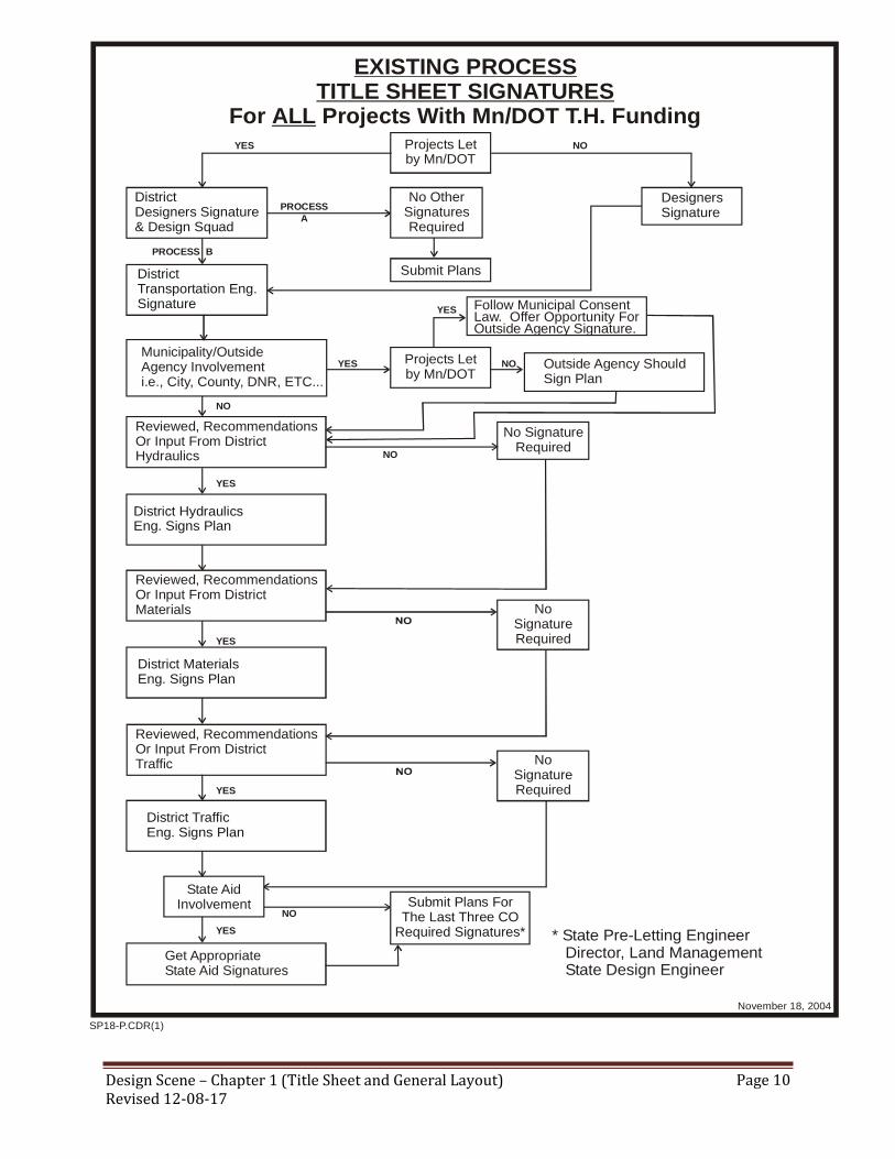
TITLE SHEET SIGNATURE BLOCK
Each District is responsible for reviewing their final plans prior to submittal to the Pre Letting Services
Section. The title sheet shall be signed as recommending for approval by the District Materials
Engineer, District Traffic Engineer and District Hydraulics Engineer when these functional groups have
provided input to the design. If they have not provided input they do not need to sign the plan. In these
cases remove their signature block.
ALL title sheet signatures must be wet (original) signatures and cannot be computer generated
(electronic).
For a consultant designed plan (State Letting): the District Materials, Hydraulics or Traffic Engineer
shall review and sign the plan before C.O. functional group review.

Design Scene – Chapter 1 (Title Sheet and General Layout) Revised 12-08-17
Page 9
For agreement plans (let by others - not designed by MnDOT): The plan will go through the C.O.
functional group review.
For cooperative plans (State letting): If other work is inserted into our plan, it is understood we are
approving the work on MnDOT right-of-way.
For plans that have, for instance, no hydraulic considerations, their signature area can be removed.
Even though designers are required to sign every sheet in the plan, the signing of the title sheet is still
required. There are several examples of title sheets with signature blocks in the system (see article
above “TITLE SHEET ACCESS”). There is also one showing a state aid signature block.
The design engineers signature must include his/her printed name as required by the Minnesota Board
of Architecture, Engineering, Land Surveying, Landscape Architecture, Geoscience and Interior
Design (AELSLAGID). An example can be found at… http://mn.gov/aelslagid/stampinfo.html
See following flow chart for the signature process for all projects:
Design Scene – Chapter 1 (Title Sheet and General Layout) Revised 12-08-17
Page 10
SP18-P.CDR(1)
November 18, 2004
* State Pre-Letting Engineer Director, Land Management State Design Engineer
EXISTING PROCESSTITLE SHEET SIGNATURES
ALLFor Projects With Mn/DOT T.H. Funding
Get AppropriateState Aid Signatures
Projects Letby Mn/DOT
Projects Letby Mn/DOT
Submit Plans
DistrictDesigners Signature & Design Squad
DistrictTransportation Eng.Signature
Municipality/OutsideAgency Involvementi.e., City, County, DNR, ETC...
Outside Agency ShouldSign Plan
Follow Municipal ConsentLaw. Offer Opportunity ForOutside Agency Signature.
District HydraulicsEng. Signs Plan
District MaterialsEng. Signs Plan
DesignersSignature
YES
YES
YES
YES
NO
PROCESS
A
PROCESS B
NO
NO
NO
No SignatureRequired
Reviewed, RecommendationsOr Input From DistrictHydraulics
Reviewed, RecommendationsOr Input From DistrictMaterials
Reviewed, RecommendationsOr Input From DistrictTraffic
NoSignatureRequired
NoSignatureRequired
State AidInvolvement
District TrafficEng. Signs Plan
NO
YES
YES
YES
Submit Plans ForThe Last Three CO
Required Signatures*
No OtherSignaturesRequired

Design Scene – Chapter 1 (Title Sheet and General Layout) Revised 12-08-17
Page 11
TRIBAL LANDS It is strongly encouraged that, if applicable, all federally recognized tribal land boundaries be identified
in the plan. As a minimum these should be shown on the general layout sheets if applicable. If there
are no general layout sheets then show the boundaries on the title sheet index map. This will assist in
providing direction for MnDOT policy, procedures, and requirements when working on or near tribal
lands and assists in being mindful of issues of tribal sovereignty and jurisdiction. More information
can be found at MnDOT A to Z, “Tribes and Transportation” and “Tribal Lands” websites.
WHEN DO YOU NEED ANOTHER SP With the new federal requirements we can no longer let side work within ½ mile be part of the original
SP. Therefore, whenever work is being done on a separate control section, even if it is less than ½ mile,
it will probably require a separate SP number.
There are rare exceptions to this so if the designer believes theirs is a rare case they need to verify with
the Project Design Services Engineer to be sure.

Design Scene – Chapter 2 (Quantities & Tabulations) Revised 12-08-17
Page 1
CHAPTER 2: QUANTITIES and TABULATIONS
2018 SPEC BOOK
The effective date for the 2018 Spec Book is the January 26, 2018 letting.
All project documents submitted for the January 26, 2018 letting, or later lettings, must be in
accordance with the 2018 Spec Book. If your project is let on or after January 26, 2018, it must use
the 2018 Spec Book. If you think your project should be granted an exemption from this
requirement, submit a written request to the State Design Engineer (with justification) as soon as
possible.
As part of the 2018 Spec Book the Bid item numbering is changing to be more consistent with the
special provision numbering convention. This will allow for a higher degree of quality, in addition
to making our estimating and specification updating more consistent moving forward.
Therefore, make sure that all plans on or after January 26, 2018 use this new numbering convention.
The .6XX numbers will still require a special provision write-up for them. The following is a list of
what the new trail numbers will be for ALL items.
Special
Provision
Numbering
Standard
Specification
Numbering
Plan Unit
Description
Special
Provision
Numbering
Standard
Specification
Numbering
Plan Unit
Description
.601 .501 LUMP SUM .615 .515 ASSEMBLY
.602 .502 EACH .616 .516 SYSTEM
.603 .503 LIN FT .617 .517 SQ FT/DAY
.604 .504 SQ YD .618 .518 SQ FT
.605 .505 ACRE .619 .519 ROAD STA
.606 .506 GALLON .620 .520 YARD
.607 .507 CU YD .621 .521 DOLLAR
.608 .508 POUND .622 .522 MBM
.609 .509 TON .623 .523 M GALLON
.610 .510 HOUR .624 .524 TREE
.611 .511 DAY .625 .525 SHRUB
.612 .512 WEEK .626 .526 VINE
.613 .513 UNIT DAY .627 .527 PLANT
.614 .514 STRUCTURE .628 .528 SYSTEM

Design Scene – Chapter 2 (Quantities & Tabulations) Revised 12-08-17
Page 2
Other changes/errors in the new 2018 Spec Book as it relates to putting a plan together (2### Spec
Numbers) as we know them so far.
The following items have been added to TRNS*PRT as a result of the 2018 SPEC
BOOK….….
Several items have been added to the 2018 Spec Book resulting in the tail number changing
from the .6## series to the .5## series. Some of them are…
Under Spec 2545 the descriptions have changed as follows…
UNDERGROUND WIRE 1 COND NO 0 changed to UNDERGROUND WIRE 1/C 0
AWG .
DIRECT BURIED LIGHTING CABLE 4 COND NO 2 changed to DIRECT BURIED
LIGHTING CABLE 4 COND 2 AWG .
Item Number Short Description Unit Name
2104.502 REMOVE REFERENCE LOCATION SIGN EACH
2104.502 SALVAGE REFERENCE LOCATION SIGN EACH
2215.509 CEMENT TON
2215.509 AGGREGATE BASE TON
2215.509 BITUMINOUS MATERIAL FOR MIXTURE TON
2390.504 COLD-IN-PLACE RECYCLED/COLD CENTRAL PLANT RECYCLING SQ YD
2515.502 CONCRTE ARMOR UNITS A-36 EACH
2515.504 CONCRTE ARMOR UNITS A-34 SQ YD
2515.504 CONCRTE ARMOR UNITS A-36 SQ YD
2564.502 INSTALL REFERENCE LOCATION SIGN EACH
2564.508 STRUCTURAL STEEL-POSTS FOR OH SIGNS (D) POUND
2564.508 STRUCTURAL STEEL-TRUSSES FOR OH SIGNS (D) POUND
2564.508 STRUCTURAL STEEL-WALKWAY SUPPORT FOR OH SIGNS (D) POUND
2564.508 STRUCTURAL STEEL-PANEL MOUNT POST FOR OH SIGNS (D) POUND
2564.508 STRUCTURAL STEEL-WALKWAY GRATING FOR OH SIGNS (D) POUND
2573.502 WHEEL WASH OFF EACH
2575.504 FLEXIBLE CONCRETE GEOGRID MAT SQ YD
2575.504 TEMPORARY GEOTEXTILE COVERING SQ YD
2577.502 ROOT WAD EACH
2577.507 ROOT RAP CU YD
2016 Spec
Item #
2018 Spec
Item #Description Units
2105.604 2105.504 GEOTEXTILE FABRIC TYPE # SQ YD
2118.607 2118.507 AGGREGATE SURFACING (CV) FROM STOCKPILE CU YD
2118.607 2118.507 AGGREGATE SURFACING (CV) CLASS # CU YD
2564.602 2564.502 INSTALL MARKER EACH
2564.602 2564.502 INFILTRATION AREA MARKER X3-6A EACH
2564.602 2564.502 INSTALL DELINEATOR EACH

Design Scene – Chapter 2 (Quantities & Tabulations) Revised 12-08-17
Page 3
OVERHEAD LIGHT CABLE 1 COND NO 3/0 changed to OVERHEAD LIGHTING
CABLE 1/C 3/) AWG .
Under Spec 2564 the whole description was changed as follows….
Under Spec 2582 the word “EPOXY” was changed to “MULTI COMP”.
Page 98, ITEM 2105.604 GEOTEXTILE FABRIC TYPE # and Page 413 item 2511.504
GEOTEXTILE FILTER TYPE #…the Roman numeral (I, II, III, etc.) for the type has been
replaced with the Alpha character (1, 2, 3, etc.).
Spec 2106 EXCAVATION AND EMBANKMENT-COMPACTED VOLUME METHOD…
Page 99, Spec 2106.1A.7…Topsoil excavation is included in the Excavation-
Common item and is NOT paid for separately. See design scene article in Chapter 4
on how this is handled.
Page 108, Spec 2106.5K…Note 2, when using this item the plan should contain a
note stating how it is modified.
Page 128, Spec 2215…
Item 2105.509 CEMENT should be item 2215.509
Item 2211.509 AGGREGATE BASE CLASS # should be 2215.509 AGGREGATE
BASE.
Page 210, Spec 2360 PLANT MIXED ASPHALT PAVEMENT… Item 2106.509 TYPE SP*
NON-WEARING COURSE MIXTURE should not have a dash between non and earing it
should be a space (e.g. Non Wearing)
Page 232, Spec 2390 COLD-IN-PLACE RECYCLED (CIR) BITUMINOUS AND COLD
CENTRAL PLANT RECYCLING (CCPR) BITUMINOUS…
Item 2105.509 CEMENT should be item 2215.509.
Item 2211.509 AGGREGATE BASE, CLASS # is in the wrong spec., it should be
2215.509 AGGREGATE BASE.
Page 433, Spec 2533 CONCRETE MEDIAN BARRIERS…THE * NOTE SHOULD
INCLUDE “OR PLAN”.
Page 451 & 453, Item 2545.501 LIGHTING SYSTEM by LUMP SUM…
Now includes the removal/salvage and disposal of the miscellaneous structures, conduit,
wiring, and lighting equipment from the existing system.
If any of this system is being salvaged the designer still needs to include a pay item for
2104.601 HAUL SALVAGED MATERIAL by LUMP SUM and note what is being hauled.
If the lighting system is owned by the city/county the Feds won’t pay for the
removal/salvage but will pay for the new/installation. Contact the MnDOT Agreements
section on how to show this in the SEQ.
2016 Spec Item # 2016 Spec Description 2018 Spec Item # 2018 Spec Description Units
2564.550/00301 DELINEATOR TYPE X3-1 2564.502/00301 RIGHT OF WAY MARKER TYPE X3-1 EACH

Design Scene – Chapter 2 (Quantities & Tabulations) Revised 12-08-17
Page 4
Page 501, Spec 2565 TRAFFIC CONTROL SIGNALS…the typical unit of SIGNAL SYSTEM
has been changed to just “SYSTEM”.
Page 521, Spec 2573 STORM WATER MANAGEMENT …Item 2573.504 SEDIMENT
TRAP EXCAVATION should be item 2573.507 and move down one on the list to stay in
sequential numerical order by item number.
Page 527, Spec 2575.3C.3 TYPE 4 MULCH should read….3884, HYDRAULIC
STABILIZED FIBER MATRIX…
Page 540, Spec 2580 INTERIM PAVEMENT MARKING…
Item 2102.501 INTERIM PAVEMENT MARKING should be 2580.501.
Item 2102.503 INTERIM PAVEMENT MARKING should be 2580.503.
2112 SHOULDER PREPARATION There has been some confusion on how to determine the quantity for 2112 Shoulder Preparation in
the plans. This needs to be further clarified so this section is revised as follows….
When the shoulder preparation work is not continuous (random) it should be paid for by the LIN FT
and each shoulder is counted separately. By that I mean that for a 100 foot stretch of roadway if the
project is prepping only one side of the road (one shoulder) it is only 100 linear feet. But if the
project is prepping both shoulders then the quantity would be 200 linear feet. Use 2112.603
SHOULDER PREPARATION by LIN FT the measurement will be made by the linear foot along
the shoulder of the roadway where shoulder preparation is performed as specified.
When the shoulder preparation work is a continuous length of work (left and right sides roughly
equal start and stop locations for both sides of the road) it should be paid for by the ROAD
STATION and the measurement includes both shoulders of the roadway, do NOT double the
quantity for this. By that I mean that for a 100 foot stretch of roadway the quantity would be 1 road
station. Use 2112.619 SHOULDER PREPARATION by ROAD STA the measurement will be
made by length in road stations of 100 feet along the centerline of the roadway where shoulder
preparation is performed as specified.
ALTERNATE BID The Minnesota Department of Transportation (MnDOT) has made a decision to develop alternate
bid pavement plans for rehabilitation projects that fall within a certain threshold. See the letter from
the Office of Materials and Road Research dated September 1, 2011 at…
http://ihub.dot.state.mn.us/operations/documents/Ops_Handout_09092011.pdf
These alternate bid pavement plans will allow certain rehabilitation projects to be bid by both
bituminous and concrete contractors.
A committee was formed to formulate the following guidelines for alternate bid projects….
Design Scene – Chapter 2 (Quantities & Tabulations) Revised 12-08-17
Page 5
General Themes
As the committee discussed the sections of the plan two thoughts became prominent. The first was
that as much of the plan as possible should be common to both alternates. Having as much of the
plan as possible common to both alternates should keep the plan size reduced to nearly the same size
as a single alternate rehabilitation project.
The second thought was that all information relating to alternates should be clearly and consistently
labeled to provide a contractor as much clarity as possible in distinguishing between alternates. The
committee selected to label alternates using numbers rather than letters for statewide consistency.
The alternate number should be followed by a description of the alternate. An example would be
“Alternate 1 – Reclamation and Bituminous Surfacing, Alternate 2 – Concrete Overlay”. This
labeling should be used consistently throughout the plan wherever alternate paving information is
shown.
Recommendations for Plan Format
Title Sheet
The title on the title sheet should clearly state that the plan is an alternate pavement plan, e.g.:
CONSTRUCTION PLAN FOR Grading, Alternate Bituminous or Concrete Surfacing, etc.
Statement of Estimated Quantities
Pay for the bituminous quantities by the ton and pay for concrete with two items, Sq Yd for Place
Concrete Material and cubic yard for the structural concrete. This is consistent with the September
1, 2011 letter from the Office of Materials and Road Research.
1) The alternate bid quantities should be part of the main SEQ and not in separate SEQs. The
alternate bid quantities should be at the end of the SEQ. The alternates should be slightly
separated from the other items in the SEQ and clearly labeled as discussed under General
Themes section of this report. Only those items directly related to the alternate pavement
design should be listed in the alternate sections of the SEQ. In some cases, there may be
items such as striping listed in the alternate sections because those items change with the
pavement selected.
2) In the case where the milling depth or the reclaim depth may vary between alternates, the
removal quantities that the alternates have in common should be shown in the common
section of the estimated quantities. For the alternate that requires the removal of extra
material, only the quantity of extra material should be shown in the alternate quantity.
General Layout and Construction Plan Sheets
For most rural plans, a General Layout should be sufficient to convey the anticipated construction.
Plan details can be added later in the plan to show information that may be required for culvert
replacement, superelevation transitions, etc.
1) Construction Plans sheets may be needed if a rural project involves inslope grading over the
length of the project due to crown or superelevation correction. In these cases, erosion

Design Scene – Chapter 2 (Quantities & Tabulations) Revised 12-08-17
Page 6
control, turf establishment, culvert adjustments, etc. may need to be shown on a more
detailed Construction Plan type sheet. As much information as possible should be shown on
one sheet to minimize the size of the plan set.
2) For urban projects, Construction Plan sheets may be necessary to show locations of storm
sewer facilities, ADA improvements, etc.
Profiles
Profiles are generally not needed unless there are intentional corrections to the profile to correct
sight distance or bridge clearance.
Typical Sections
Use common typical sections where possible for existing typical and perhaps the milling and/or
reclaiming.
1) Clearly label typical sections for alternates with the convention listed under the General
Themes section of this report.
2) Each alternate should have its own typical section(s). Do not split a typical section between
alternates (show the bituminous alternate left of centerline and the concrete alternate right of
centerline).
As per the September 1, 2011 letter from the Office of Materials and Road Research, the pavement
widths should be the same if possible. Pavement widths may not be 26 feet, however, due to the
width of the underlying pavements upon which the new surface will be constructed.
Tabulated Quantities and Construction Notes
Most tabulated quantities and construction notes should be common to both alternatives. Tabulated
quantities and construction notes that pertain to only one alternate should be clearly labeled as
described in the General Themes section of this report.
Traffic Control
1) Alternate bid plans requiring reclaiming will typically require a detour for both alternates.
The same detour should be used.
2) Alternate bid plans requiring milling may only require a detour for the concrete paving since
the bituminous overlay could typically be done under traffic. In the case of milling type
projects, several options could be considered by the District:
a. Require the bituminous contractor use the same detour as the concrete contractor.
This would keep consistency between the options and would allow the bituminous
contractor the same unobstructed work site as the concrete contractor. If bridge or
culvert replacement is part of a project, this may be the natural course of action.
Depending upon the length of detour and business impacts, this option may not be
desirable from the public’s perspective.
b. Require the bituminous contractor to work under traffic. This could require the
traffic control to be considered as part of the alternate bid portion of the estimated
quantities since it would be drastically different for the two alternatives. This option
could be more desirable from a road user and business perspective. However, the
Design Scene – Chapter 2 (Quantities & Tabulations) Revised 12-08-17
Page 7
bituminous contractor is not allowed the same unobstructed work site as the concrete
contractor and heavy traffic volumes may reduce production rates or require night
work.
c. Design the same detour plan for both options, but allow contractors to work under
traffic if they desire. Contractors choosing to work under traffic could not submit the
proposal under value engineering. A more formalized way to deal with this option,
however, would be to set up an A+B contract where the B portion is determined by
the number of days that the contractor would use the detour. This would allow the
contractors the greatest flexibility, but would not necessarily be the best way to
address user costs and business impacts.
3) The decision on Traffic Control for mill and overlay type projects will need to be addressed
on a case by case basis considering other work types in the project that may require a detour,
traffic volumes that may hinder productivity, business impacts, and available and reasonable
detour routes.
Cross-sections
With many rehabilitation projects, cross-sections will not be needed as part of the plan set.
1) Some rehabilitation projects may require minor inslope work. The inslope work may not be
readily visible on cross-sections drawn for the plan. In these cases, the cross-sections may
be omitted from the plan, even though they may need to be developed to calculate quantities.
Other Issues
Other issues affecting project delivery were also discussed.
1) The designer should request a life cycle cost from the pavement engineer at the time of plan
turn in. This will allow the pavement engineer sufficient time to develop the life cycle cost
adjustment factor for the bidding process.
2) A standard specification for pavement smoothness has been developed for alternate
pavement projects. This specification should be incorporated into the special provisions.
3) Alternate bid projects should not be combined with single alternate projects. These
combinations could skew the bid of the alternate pavement to the pavement type selected for
the other portion of the project.
4) Alternate bid projects should not be combined with other alternate bid projects. If a District
desires to combine two alternate bid projects, the District should work with the pavement
engineer to see if common typical sections and life cycle costs can be used over the length of
both projects.
5) Districts may use A+B bidding in conjunction with alternate pavements. A+B contracts may
be desirable when a significant difference in working days between alternates is anticipated.
Use 2301.504 “Concrete Pavement __” ” by the SQ YD pay item when 2360 pay items are Square
Yard. Use 2301.504 “Place Concrete Pavement __” ” by the SQ YD and 2301. 507 “Structural
Concrete” by CU YD pay items when 2360 pay items are Tons.

Design Scene – Chapter 2 (Quantities & Tabulations) Revised 12-08-17
Page 8
BRIDGES & BOX CULVERTS There has been come confusion this season in how Bridge items are documented in project plans
and financial information. There is also a need to reinforce how these items are tracked for financial
purposes.
The following guidance is related to Bridge replacements, new Bridges and Box Culverts with or
without Bridge numbers.
Bridge Replacements:
Bridge/Box Culvert Replaced with Bridge
If you have an existing bridge/culvert with a Bridge number that is replaced with a new bridge, the
new bridge has a Bridge plan completed that is attached as a separate plan. Bridge plans are not
embedded in the grading plans but rather attached at the end.
The existing and new bridge numbers are identified on the Grading plan title sheet index map (e.g.
Remove Br. No XXX, Proposed Br. No. XXX) and the new bridge is included in the project
description. The Bridge pay items (in the bridge plan only) and quantities are in a separate
cost/funding group or groups. The Bridge numbers (new and existing) should also be identified in
the appropriate sections of the plan such as the general layout, construction plans and profiles.
Bridge/ Box Culvert Replace with Box Culvert 10’ and Over
If you have an existing bridge/culvert with Bridge number that is replaced with a Box culvert that is
10 ‘ or over and has a Bridge number, the new box culvert has plan sheets that are incorporated
INTO the Grading Plan.
The existing bridge and new box culvert bridge numbers are identified on the Grading plan title
sheet index map (e.g. Remove Br. No XXX, Proposed Box Culvert. No. XXX) and the new bridge
is included in the project description. The pay items and quantities for each individual box culvert
and end sections are in separate cost/funding group or groups. Since these items are included in the
grading plan quantities, the items must have footnotes on the SEQ referencing the culvert and end
sections that are for the specific Bridge number noted on the Box culvert. When the project includes
multiple box culverts of the same size with different bridge numbers, the footnotes need to identify
the quantities for each bridge number. The Bridge numbers (new and existing) should also be
identified in the appropriate sections of the plan such as the general layout, construction plans and
profiles.
Example of Single Bridge/Box Culvert
NOTES ITEM DESCRIPTION UNIT QUANTITY
(2) 2412.502 12X11 PRECAST CONCRETE BOX CULVERT END SECT EACH 2
(2) 2412.503 12X11 PRECAST CONCRETE BOX CULVERT LIN FT 150
(1) 2442.501 REMOVE EXISTING BRIDGE LUMP SUM 1
(1) Bridge No. 1234 consists of 25'x25' concrete beam structure.
(2) Box Culvert No. 23X10, Replaces Bridge No. 1234.

Design Scene – Chapter 2 (Quantities & Tabulations) Revised 12-08-17
Page 9
Bridge/ Box Culvert Replace with Box Culvert under 10’
If you have an existing bridge/culvert with Bridge number that is replaced with a Box culvert that is
less than 10’, it will not have a bridge number but will have box culvert plan sheets that are
incorporated into the Grading Plan.
The existing bridge number being replaced is identified on the Grading plan title sheet index map
(e.g. Remove Br. No. XXX) and included in the project description. The pay items and quantities
for each individual box culvert and end sections are in separate cost/funding group or groups. Since
these items are included in the grading plan quantities, the items must have footnotes on the SEQ
referencing each individual culvert and end sections that are for the specific Bridge number being
replaced. When the project includes multiple box culverts of the same size replacing existing
structures (with bridge numbers), the footnotes need to identify the quantities for each existing
bridge number. The Bridge numbers (existing) should also be identified in the appropriate sections
of the plan such as the general layout, construction plans and profiles.
Example of Single Box Culvert/Box Culvert
NOTES ITEM DESCRIPTION UNIT QUANTITY
(1) 2104.502 REMOVE CONCRETE BOX CULVERT END SECTION EACH 2
(1) 2104.503 REMOVE CONCRETE BOX CULVERT LIN FT 130
(2) 2412.502 12X11 PRECAST CONCRETE BOX CULVERT END SECT EACH 2
(2) 2412.503 12X11 PRECAST CONCRETE BOX CULVERT LIN FT 150
(1) Bridge No 1234, 12x10 Box Culvert.
(2) Box Culvert No 23X10, Replaces Bridge No. 1234.
Example of Multiple Bridges/Box Culvert
NOTES ITEM DESCRIPTION UNIT QUANTITY
(4) 2412.502 12X11 PRECAST CONCRETE BOX CULVERT END SECT EACH 6
(4) 2412.503 12X11 PRECAST CONCRETE BOX CULVERT LIN FT 350
(1) 2442.501 REMOVE EXISTING BRIDGE A LUMP SUM 1
(2) 2442.501 REMOVE EXISTING BRIDGE B LUMP SUM 1
(3) 2442.501 REMOVE EXISTING BRIDGE C LUMP SUM 1
(1) Bridge No. 1234 consists of 25'x25' concrete beam structure.
(2) Bridge No 5678 consists of 20' timber structure.
(3) Bridge No 9123 consists of 35' x 35' concrete beam structure.
(4) Box Culvert no 23X10 = 100' with 2 end sections, Replaces Bridge No. 1234.
Box Culvert No 23X11 = 150' with 2 end sections, Replaces Bridge No. 5678.
Box Culvert No 23X12 = 100' with 2 end sections, Replaces Bridge No. 9123.
Example of Single Bridge/Box Culvert
NOTES ITEM DESCRIPTION UNIT QUANTITY
(2) 2412.502 8X8 PRECAST CONCRETE BOX CULVERT END SECT EACH 2
(2) 2412.503 8X8 PRECAST CONCRETE BOX CULVERT LIN FT 150
(1) 2442.501 REMOVE EXISTING BRIDGE LUMP SUM 1
(1) Bridge No. 1234 consists of 25'x25' concrete beam structure.
(2) Replaces Bridge No. 1234.

Design Scene – Chapter 2 (Quantities & Tabulations) Revised 12-08-17
Page 10
Bridge/ Box Culvert Replace with Pipe
If you have an existing bridge/culvert with Bridge number that is replaced with a pipe, it will not
have a new bridge number but will have plan sheets that are incorporated into the Grading Plan.
The existing bridge number being replaced is identified on the Grading plan title sheet index map
(e.g. Remove Br. No. XXX) and included in the project description. The pay items and quantities
for the pipe and end sections are in a separate cost/funding group or groups. Since these items are
included in the grading plan quantities, the items must have footnotes on the SEQ referencing the
pipe and end sections that are for each individual Bridge number being replaced. When the project
includes multiple pipes of the same size replacing existing structures (with bridge numbers), the
footnotes need to identify the quantities for each existing bridge number. The Bridge numbers
(existing) should also be identified in the appropriate sections of the plan such as the general layout,
construction plans and profiles.
Example of Single Box Culvert/Box Culvert
NOTES ITEM DESCRIPTION UNIT QUANTITY
(1) 2104.502 REMOVE CONCRETE BOX CULVERT END SECTION EACH 2
(1) 2104.503 REMOVE CONCRETE BOX CULVERT LIN FT 130
(2) 2412.502 8X8 PRECAST CONCRETE BOX CULVERT END SECT EACH 2
(2) 2412.503 8X8 PRECAST CONCRETE BOX CULVERT LIN FT 150
(1) Remove 6'x8' box culvert and end sections.
(2) Replaces 6'x8' box culvert with end sections.
Example of Multiple Bridges/Box Culvert
NOTES ITEM DESCRIPTION UNIT QUANTITY
(4) 2412.502 12X11 PRECAST CONCRETE BOX CULVERT END SECT EACH 6
(4) 2412.503 12X11 PRECAST CONCRETE BOX CULVERT LIN FT 350
(1) 2442.501 REMOVE EXISTING BRIDGE A LUMP SUM 1
(2) 2442.501 REMOVE EXISTING BRIDGE B LUMP SUM 1
(3) 2442.501 REMOVE EXISTING BRIDGE C LUMP SUM 1
(1) Bridge No. 1234 consists of 25'x25' concrete beam structure.
(2) Bridge No 5678 consists of 20' timber structure.
(3) Bridge No 9123 consists of 35' x 35' concrete beam structure.
(4) Box Culvert at Station 101+00 = 100' with 2 end sections, Replaces Bridge No. 1234.
Box Culvert at Station 105+70 = 150' with 2 end sections, Replaces Bridge No. 5678.
Box Culvert at Station 120+35 = 100' with 2 end sections, Replaces Bridge No. 9123.
Example of Single Bridge/Box Culvert
NOTES ITEM DESCRIPTION UNIT QUANTITY
(1) 2442.501 REMOVE EXISTING BRIDGE LUMP SUM 1
(2) 2501.502 72" RC SAFETY APRON & GRATE DES 3132 EACH 2
(2) 2501.503 72" RC PIPE CULVERT CLASS IV LIN FT 150
(1) Bridge No. 1234 consists of 25'x25' concrete beam structure.
(2) Replaces Bridge No. 1234.

Design Scene – Chapter 2 (Quantities & Tabulations) Revised 12-08-17
Page 11
New Bridges:
New Bridge
If you have a new bridge, the new bridge has a Bridge plan completed that is attached to the Grading
Plan. The new bridge number is identified on the Grading plan title sheet index map and included in
the project description. The Bridge pay items and quantities are in a separate cost/funding group or
groups. Bridge plans are not embedded in the grading plans but rather attached at the end. The
Bridge numbers (new) should also be identified in the appropriate sections of the plan such as the
general layout, construction plans and profiles.
New Box Culvert 10’ or Over
If you have a new Box culvert that is 10 ‘or over and has a Bridge number, the new box culvert has
plan sheets that are incorporated into the Grading Plan. The new box culvert bridge numbers are
identified on the Grading plan title sheet index map (Proposed Box Culvert No. XXxXX) and
included in the project description. The pay items and quantities for each individual box culvert and
end sections are in a separate cost/funding group or groups. Since these items are included in the
grading plan quantities, the items must have footnotes on the SEQ referencing the culvert and end
sections that are for the specific Bridge number noted on the Box culvert. When the project includes
multiple box culverts of the same size with different bridge numbers, the footnotes need to identify
the quantities for each bridge number. The Bridge numbers (new) should also be identified in the
appropriate sections of the plan such as the general layout, construction plans and profiles.
Example of Single Box Culvert/Box Culvert
NOTES ITEM DESCRIPTION UNIT QUANTITY
(1) 2104.502 REMOVE CONCRETE BOX CULVERT END SECTION EACH 2
(1) 2104.503 REMOVE CONCRETE BOX CULVERT LIN FT 130
(2) 2501.502 72" RC SAFETY APRON & GRATE DES 3132 EACH 2
(2) 2501.503 72" RC PIPE CULVERT CLASS IV LIN FT 150
(1) Remove 6'x8' box culvert and end sections.
(2) Replaces 6'x8' box culvert.
Example of Multiple Bridges/Box Culvert
NOTES ITEM DESCRIPTION UNIT QUANTITY
(1) 2442.501 REMOVE EXISTING BRIDGE A LUMP SUM 1
(2) 2442.501 REMOVE EXISTING BRIDGE B LUMP SUM 1
(3) 2442.501 REMOVE EXISTING BRIDGE C LUMP SUM 1
(4) 2501.502 72" RC SAFETY APRON & GRATE DES 3132 EACH 6
(4) 2501.503 72" RC PIPE CULVERT CLASS IV LIN FT 350
(1) Bridge No. 1234 consists of 25'x25' concrete beam structure.
(2) Bridge No 5678 consists of 20' timber structure.
(3) Bridge No 9123 consists of 35' x 35' concrete beam structure.
(4) Culvert at Station 101+00 = 100' with 2 end sections, Replaces Bridge No. 1234.
Culvert at Station 105+70 = 150' with 2 end sections, Replaces Bridge No. 5678.
Culvert at Station 120+35 = 100' with 2 end sections, Replaces Bridge No. 9123.

Design Scene – Chapter 2 (Quantities & Tabulations) Revised 12-08-17
Page 12
New Box Culvert under 10’
If you have a new Box culvert that is less than 10’, it will not have a bridge number but will have
box culvert plan sheets that are incorporated into the Grading Plan. The box culverts are not
identified on the Grading plan title sheet or included in the project description. The pay items and
quantities for box culverts and end sections without bridge numbers are incorporated into the
grading cost/funding group.
Items such as grading, pavement, guardrail, riprap, erosion control, and turf are not required or
recommended for inclusion in the box culvert cost groups (unless it is shown in the items on
separate Bridge SEQ’s/Plans) to aid in more efficient contract management in the field.
CITY/COUNTY FUNDS When you have a plan that has city/county funds include the name of the city or county that is
participating in the costs. Place the name with the funding information either in the SEQ column
heading or in a funding note.
If there is a State Aid SP or SAP on a project the plan will require either one or two signatures from
the State Aid office on the title sheet. For appropriate signature block descriptions and signatures
from the State Aid office contact the District State Aid office. If the plan requires CO State Aid to
sign the title sheet obtain the signature or make arrangements with CO State Aid to sign.
COMBINATION FIELD LABORATORY OFFICE Whenever this item is used in the plan it needs to include a note in the estimated quantity
table…REQUIRES TYPE??? SERVICE.
CONCRETE MEDIAN BARRIER DESIGN TYPE AA Concrete median barrier should be measured and paid for separately by type. Type A, Type AL and
Type transition barrier lengths are measured along the top of the barrier, essentially one foot of
Example of Single Bridge/Box Culvert
NOTES ITEM DESCRIPTION UNIT QUANTITY
(1) 2412.502 12X11 PRECAST CONCRETE BOX CULVERT END SECT EACH 2
(1) 2412.503 12X11 PRECAST CONCRETE BOX CULVERT LIN FT 150
(1) Box Culvert No 23X10.
Example of Multiple Bridges/Box Culvert
NOTES ITEM DESCRIPTION UNIT QUANTITY
(1) 2412.502 12X11 PRECAST CONCRETE BOX CULVERT END SECT EACH 6
(1) 2412.503 12X11 PRECAST CONCRETE BOX CULVERT LIN FT 350
(1) Box Culvert no 23X10 = 100' with 2 end sections
Box Culvert No 23X11 = 150' with 2 end sections
Box Culvert No 23X12 = 100' with 2 end sections

Design Scene – Chapter 2 (Quantities & Tabulations) Revised 12-08-17
Page 13
barrier for each foot of median. Type AA barrier is also measured along the top of the barrier but
each side is measured separately.
CULVERT/STORM TREATMENTS
When these details are included in the plan it needs to be clear how the excavation is being paid for.
This CANNOT be incidental as this is over and above what a culvert excavation would be. Make
sure the detail makes it clear how the excavation is being paid for and include quantities in the
earthwork tabulation to account for this work.
ESTIMATED QUANTITIES FORMAT The quantities put on the estimate sheet should normally be rounded to the nearest whole number.
We should avoid using decimals, if possible. Only in cases of extremely small quantities should
decimals be used and then only to the tenth place.
Commas should not be used either. For large numbers either leave a space where the comma would
typically go or just continue the number (e.g. 12 345 or 12345 instead of 12,345).
When using small numbers as in the case of prorate items, a zero should be placed before the
decimal number. (e.g. 0.5 instead of .5).
Do NOT use zeros or dashes in the estimated quantities table or any tabs. These locations should be
left blank.
The statement of estimated quantity (SEQ) table should begin with the tab column. This will then
be followed by the Sheet number column.
Next will be the Item number column followed by the item description column. After this will be
the units column. Be sure to follow the standard abbreviations as shown later in this chapter.
There will only be one total column. It will not have a final estimate column. The Total Estimate
Column should always follow the Unit column on the estimated quantities table. If there is more
than one SP or one funding source the Total Estimate Column should come first then the prime SP
followed by the next major SP and ending with the state aid/city/county SP . If there is only one SP
then only the total column should be shown not a total and SP column. The following is an example
of how the headings in the estimate column should be shown…
Tab Sheet
#
Item
#
Item Description Units Total
Estimated
Quantity
SP Prime
# Quantity
SP
Secondary
# Quantity
State Aid
SP #
Quantity
If there is only one SP then the following headings are recommended…

Design Scene – Chapter 2 (Quantities & Tabulations) Revised 12-08-17
Page 14
Tab Sheet
#
Item
#
Item Description Units Total
Estimated
Quantity
The sheet # column (if used) should reference the sheet that the tab is on and/or any special details
other than standard plan sheets. We do NOT reference standard plan sheets.
FOG SEAL When using item 2355 BITUMINOUS MATERIAL FOR FOG SEAL. It should include a note that
gives the dilution and mix rate. The note would read something like…
Quantity based on diluted mixture at a 1:1 rate applied at 0.08 gallons per square yard.
FUNDING As the funding has become more complicated it is necessary to make sure that it is entered into the
system correctly and shown on the plans correctly.
The funding sources (e.g. state, federal, city, county, state aid, etc.) need to be determined early in
the process. If there are multiple funding sources then the Statement of Estimated Quantities (SEQ)
and the tabulations need to show the funding splits. ALL TABS need to show the funding splits,
even traffic and drainage tabs.
Quantities on the estimated quantities sheets must be split into as many columns as there are
separate funding groups; the factors that determine funding groups are funding source, project
number, and percentage of participation. Specific funding information should be included at the top
of each group column.
MnDOT participation should be indicated by showing the percentage of MnDOT participation for
each group. When there is more than one State Project Number, each separate state funding source
is a separate group and the appropriate State Project Number should be indicated.
Local participation should be indicated by showing the percentage of local participation, and if
applicable, the State Aid Project Number. Lump sum agreements should be identified with a note at
the top of the column-or noted for the pay items that the lump sum applies to. The notes on the SEQ
sheet will need to include ….
If it is lump sum
The agreement number
Who the agreement is with
For example….

Design Scene – Chapter 2 (Quantities & Tabulations) Revised 12-08-17
Page 15
The funding percentages must total 100% for each column.
If there are federal funds and/or unique funds the SEQ needs to show the funding splits .(e.g. 80%
Federal/20% State Funds ). When there is more than one Federal Project Number, each separate
federal aid funding source is shown as a separate group and the appropriate Federal Project Number
should be indicated.
If the funding designations (80% Federal/20% State Funds) do not fit in the SEQ column headings
then they should be shown as a note. The note should be a lettered note (e.g. A, B, C, etc.) not a
numbered note. It should be set apart from the numbered notes so that it stands out and is noticed.
Do NOT use numbered notes for any funding items. Even the “100% State Funds” note should be a
lettered note.
The Federal Project Number, State Project Number, and State Aid Project Number must be shown
on the construction plan title sheet.
If federal funds are applied to the local share, the local federal funds must be identified in the STIP,
and the local share needs a federal State Aid project number.
For further information regarding cost participation information required in the construction plan,
see the “Metro Sample Plan,” MnDOT Policy for Cost Participation for Cooperative Construction
Projects and Maintenance Responsibilities between MnDOT and Local Units of Government, or
contact MnDOT’s Design Service Engineer, the Funding Program Coordinator in the MnDOT
Office of Transportation System Management, or MnDOT’s Municipal Agreements Engineer.
HAUL SALVAGED MATERIAL
Our specification (Spec. 2104 and 2442) spell out that salvaged materials will be neatly stored
within the project limits. The F.H.W.A. won’t pay to haul salvaged materials off the construction
project. If Maintenance prefers not to handle the material, the item 2104.601 Haul Salvaged
Material by the Lump Sum should be added and is state funded.
ITEM DESCRIPTION UNITS
TOTAL
ESTIMATED
QUANTITY
ESTIMATED
QUANTITY
SP 1111-11
A
EST. QUANT.
SAP 111-112-121
B
2021.501 MOBILIZATION LUMP SUM 1 0.8 0.2
2105.504 GEOTEXTILE FABRIC TYPE 3 SQ YD 150 50 100
2118.507 AGGREGATE SURFACING (CV) CLASS 1 CU YD 150 100 50
POSSIBLE NOTES….
A SEE LUMP SUM AGREEMENT NO 1234567 WITH THE CITY OF CROCKER
or A SEE AGREEMENT NO 1234567 WITH SWANSON COUNTY (57% FEDERAL, 23% COUNTY FUNDS, 20% STATE FUNDS)
or A SEE AGREEMENT NO 1234567 WITH THE CITY OF CROCKER (100% CITY FUNDS)
B SEE AGREEMENT NO 1234567 WITH THE CITY OF CROCKER (100% STATE AID FUNDS)
or B SEE AGREEMENT NO 1234567 WITH SWANSON COUNTY (80% STATE AID, 20% COUNTY FUNDS)

Design Scene – Chapter 2 (Quantities & Tabulations) Revised 12-08-17
Page 16
INCIDENTAL AND LUMP SUM ITEMS
An internal review of our existing process for the development of engineer’s estimates for
construction projects identified a number of risk areas and change needs. The following process
changes will be made immediately. These adjustments to our process will result in reducing the risk
of inadvertent disclosure of nonpublic data prior to project award per Minnesota Statute §13.72,
subd. 1.
These new procedures will be applied to all projects that are included in the MnDOT letting
process.
The INCIDENTAL, FOR INFORMATION ONLY, and LUMP SUM quantities will no longer be
supplied in the plan or special provisions. The list of elements and application rates included in the
incidental and lump sum items can be listed in the plan and special provisions but not the quantities.
FOR INFORMATION ONLY statement as associated with quantities will no longer be allowed in
the plans.
This information will be supplied in the current tabulated or listed format via a stand alone
document to the Cost Estimating Engineer and the Design Support Engineer only, at the time of
project submittal. The Preliminary Estimate and Data Base file (*.mdb) will be located in the
specific projects ProjectWise location (a right protected folder), with AD group name of
“DxEstimates” and a Folder name of “Estimates Restricted” which restricts access for anyone
except newly established AD group (Ex. Design Engineer, Lead Designer & District Cost
Estimating Engineer).
LUMP SUM ITEMS
The term, "lump sum," when used as a unit of measurement for payment, means complete payment
for that item of work as described by the contract. A description of the work to be paid for as a
“lump sum” is included in the plans so that contractors bidding on the project will know exactly
what work and materials are included in the pay item. These “lump sum” items usually include
work items that are used on many projects. Either a bill of materials has been developed for them
(such as standardized traffic control or traffic control interconnection systems) or they are routine
work items that do not vary significantly from project to project (such as maintenance or restoration
of haul roads).
Clear definition in the plan of what is expected in each case contributes to harmony and better
results at less cost during construction. More accurate estimates are promoted as well. There is no
good substitute for careful research and determination of reasonably accurate quantities. Pursuing
this a bit further - occasionally a plan provides for direct payment for certain items yet advises
bidders that certain like items of unknown quantity required to be furnished by the contractor as
included in one thing or another will not be measured for payment. This can only be
disadvantageous to the state. The bidder must again include a sufficient sum somewhere in his
proposal to cover the costs of the unknown quantity to protect themselves and then still demand
direct payment of the engineer. How can direct payment be justified for the known quantity but not
for the unknown? Better to provide that the unknown quantities will be paid for at the appropriate

Design Scene – Chapter 2 (Quantities & Tabulations) Revised 12-08-17
Page 17
contract price. Gives estimators a break, too. The preceding cases are even more confusing when the
extent of the unknown quantities is subject to “as direct (or ordered) by the engineer.”
LUMP SUM ON MULTIPLE COLUMN OR TIED PLANS
There has been some confusion on how to show quantities for Lump Sum (non-prorated) (see
PRORATA ITEMS article in this chapter) on multiple column plans and tied plans.
For multi column plans and/or tied plans
A quantity of 1 should be placed under the total column and the prime S.P. column. All the
other S.P. columns should be left blank, or
If it only applies to a column (not the prime S.P.) then the 1 should go in that column, or
If the designer feels it is absolutely necessary to split the item then it can be divided between the
various columns or tied plan, based on the amount of work needed for that work not based on
cost. The decimal for these items can only go to the tenths place.
Examples can be found at….
http://www.dot.state.mn.us/pre-letting/scene/docs/seq-tabs-multi-sp-funds-guidance.pdf
MAINTENANCE AND RESTORATION OF HAUL ROADS The pay item 2105.501 “Maintenance and Restoration of Haul Roads” Lump Sum should be used on
all projects that require raw materials to be hauled to or from the job site. Such as projects that
include, but are not limited to, Borrow items, Bituminous materials, Concrete materials.
Stand-alone projects such as crack repairs, landscaping, striping, and guardrail would not need the
pay item in the SEQ.
MOBILIZATION ITEM The item is intended to cover the contractor’s costs to mobilize labor and equipment to the project as
well as other costs such as performance bond, job superintendent, testing, engineering and
miscellaneous costs that have not been assigned to another bid item.
Occasionally, we see a plan without the mobilization item included. Since mobilization is a real
cost to contractors, they must add their mobilization cost to the cost of another item(s). This
unbalancing of bid items can distort average bid prices generated for the purpose of estimating. In
the interests of providing the most accurate historical bid prices for construction, it is important to
include a bid item for mobilization in our plans. The few exceptions to this would be standalone
projects such as, but not limited to, landscaping, signal, TMS, and lighting jobs.
PLAN QUANTITIES (P)
The “P” designation on individual Contract Items or specific portions of Contract Items in the
Statement of Estimated Quantities on the Plan means that Plan dimensions will be used to calculate
the pay quantity for that Contract Item. The purpose of the use of “P” designated quantities is to

Design Scene – Chapter 2 (Quantities & Tabulations) Revised 12-08-17
Page 18
avoid the expense of measuring dimensions in the field, if original Plan dimensions remain valid.
The use of “P” designated quantities is limited to Contract Items with specified dimensions that can
be controlled by field checks during, or after construction.
Items with the “P” designation must have quantities that are calculated using dimensions in the plan.
Some examples of Items where a “P” designation might be appropriate include the following:
2101.505 CLEARING Acre
2101.505 GRUBBING Acre
2104.503 REMOVE Lin. Ft.
2104.504 REMOVE Sq. Yd.
2104.518 REMOVE Sq. Ft.
2105.507 COMMON EXCAVATION Cu. Yd.
2105.507 ROCK EXCAVATION Cu. Yd.
2105.507 MUCK EXCAVATION Cu. Yd.
2105.507 SUBGRADE EXCAVATION Cu. Yd.
2105.507 CHANNEL AND POND EXCAVATION Cu. Yd.
2105.507 ROCK CHANNEL EXCAVATION Cu. Yd.
2106.507 EXCAVATION – COMMON Cu. Yd.
2106.507 EXCAVATION – SUBGRADE Cu. Yd.
2106.507 EXCAVATION – ROCK Cu. Yd.
2106.507 EXCAVATION – MUCK Cu. Yd.
2211.507 AGGREGATE BASE (CV), CLASS _ Cu. Yd.
2221.507 SHOULDER BASE AGGREGATE (_V) CLASS _ Cu. Yd.
2232.504 MILL BITUMINOUS SURFACE ( __”) Sq. Yd.
2301.504 CONCRETE PAVEMENT _” Sq. Yd.
2301.504 PLACE CONCRETE PAVEMENT _” Sq. Yd.
2301.508 SUPPLEMENTAL PAVEMENT REINFORCEMENT Pound
2360.504 TYPE _# _COURSE MIX (_) _” THICK Sq. Yd.
2360.504 TYPE _#_ COURSE MIX (_) Sq. Yd.
2401.507 STRUCTURAL CONCRETE (MIX NO.) Cu. Yd.
2401.507 STRUCTURE EXCAVATION, CLASS _ Cu. Yd.
2401.508 REINFORCEMENT BARS Pound
2401.508 REINFORCEMENT BARS (EPOXY COATED) Pound
2401.508 STEEL FABRIC Pound
2401.508 SPIRAL REINFORCEMENT Pound
2401.508 SPIRAL REINFORCEMENT, (EPOXY COATED) Pound
2402.503 ORNAMENTAL METAL RAILING Lin. Ft.
2402.503 PIPE RAILING Lin. Ft.
2411.504 CONCRETE FOOTING Sq. Yd.
2411.507 STRUCTURAL CONCRETE (MIX NO.) Cu. Yd.
2411.507 STRUCTURE EXCAVATION, CLASS _ Cu. Yd.
2411.507 GRANULAR BACKFILL (CV) Cu. Yd.
2411.507 AGGREGATE BACKFILL (CV) Cu. Yd.

Design Scene – Chapter 2 (Quantities & Tabulations) Revised 12-08-17
Page 19
2411.508 REINFORCEMENT BARS Pound
2411.508 REINFORCEMENT BARS (EPOXY COATED) Pound
2451.507 STRUCTURE EXCAVATION, CLASS _ Cu. Yd.
2451.507 GRANULAR BACKFILL (CV) Cu. Yd.
2451.507 AGGREGATE BACKFILL (CV) Cu. Yd.
2451.507 GRANULAR BEDDING (CV) Cu. Yd.
2451.507 FINE AGGREGATE BEDDING (CV) Cu. Yd.
2451.507 COARSE AGGREGATE BEDDING (CV) Cu. Yd.
2451.507 CONDUITE AGGREGATE BEDDDING (CV) Cu. Yd.
2451.507 COURSE FILTER AGGREGATE (CV) Cu. Yd.
2451.507 FINE FILTER AGGREGATE (CV) Cu. Yd.
2461.507 CONCRETE MIX NO.___ Cu. Yd.
2501.507 CULVERT EXCAVATION, CLASS _ Cu. Yd.
2575.505 SEEDING Acre
2575.505 DISK ANCHORING Acre
Some examples of Items where a “P” designation is not appropriate include the following:
2118.509 AGGREGATE SURFACING, CLASS ___ Ton
2130.523 WATER M Gallon
2131.506 CALCIUM CHLORIDE SOLUTION Gallon
2131.509 CALCIUM CHLORIDE, TYPE___ Ton
2211.509 AGGREGATE BASE, CLASS___ Ton
2301.507 STRUCTURAL CONCRETE HIGH EARLY Cu. Yd.
2301.507 STRUCTURAL CONCRETE Cu. Yd.
2331.509 BITUMINOUS MATERIAL FOR MIXTURE Ton
2355.506 BITUMINOUS MATERIAL FOR FOG SEAL Gallon
2360.509 TYPE SP __ WEARING COURSE MIXTURE __ Ton
2360.509 TYPE SP __ NON-WEARING COURSE MIXTURE _ Ton
If only a portion of the quantity for an Item can be calculated using dimensions in the plan, then
only that portion can have the “P” designation and can be shown as follows with a footnote:
2105.507 COMMON EXCAVATION (5) Cu.Yd. 1,289,582 (985 956.4) (P)
(5) This is a partial “P” quantity. The quantity is a “P” quantity except for the
area between Sta. 842 to 851 which will be field measured. PRORATA ITEMS There has been some confusion on which items should be prorated in construction plans which involve more than one SP. Proration distributes the cost of items such as mobilization and field office among the various funding groups and/or SP’s so that they all share in the cost of these items. It should be noted that ONLY the following items should be prorated:

Design Scene – Chapter 2 (Quantities & Tabulations) Revised 12-08-17
Page 20
Mobilization Lump sum
Field Office Each
Field Laboratory Each
Traffic Control Lump Sum
The pro-rata percentage assigned to each funding split (including bridge costs, if applicable)
shown in the plans is determined by dividing the dollar value of work associated with that split
by the total dollar value of the contract (including bridge costs), less the pro-rata items.
The prorata percentage for each funding split is to be computed to two decimal places and
tabulated on the estimated quantities sheet. The designer is to use estimated quantities and
estimated prices to compute the prorata percentages. No other items should be taken to two
decimal places. (There are a few rare exceptions to this such as signals with agreements.)
Prorata percentages should be shown on the grading plan only, even when bridge costs are
included in calculation,
Special circumstances may justify an exception to these procedures. These situations should be
reviewed with the Municipal Agreements Unit and the Plan Review Unit, and the determination
of how to handle such exception will be made on a case-by-case basis.
Prorata Items Involving Cooperative Construction
A sample computation of prorata items is shown below for reference.
Sample Computation of
PRORATA ITEMS
for Cooperative Construction Agreements
Total Contract Cost (including
bridge cost) = $220,500.00
Prorata Items
Mobilization $10,000.00
Field Office $ 3,000.00
Field Laboratory $ 2,500.00
Traffic Control $ 5,000.00
Total Cost of Prorata Items $20,500.00
Total Contract Cost Minus Total Cost of Prorata Items
$220,500.00 - $20,500.00 = $200,000.00
Cost of each Funding Group & Bridge
(Cost for each group does not include cost for prorata items)

Design Scene – Chapter 2 (Quantities & Tabulations) Revised 12-08-17
Page 21
Group 1: 100% State $101,000.00
Group 2: 60% State, 40% City $ 87,200.00
Group 3: 56% State, 44% City $ 1,000.00
Group 4: 100% City $ 800.00
Bridge: 100% State $10,000.00
Prorata Percentage for each Funding Group
Group 1: ($101,000.00+$10,000.00) = 0.555 (Use 0.55)
$200,000.00
Group 2: $ 87,200.00 = 0.436 (Use 0.44)
$200,000.00
Group 3: $ 1,000.00 = 0.005 (Use 0.01) $200,000.00
Group 4:$ 800.00 = 0.004 (Use 0.00)
$200,000.00
Prorata items on Tied Plans
There has been some confusion on how to show the prorated items for tied plans.
When the tied plan has the same funding for all the SP’s.
Item No. Description Unit TOTAL A SP 1111-11TOTAL
BSP 2222-22 SP 3333-33
2021.501 MOBILIZATION LUMP SUM 1 1
2021.501 MOBILIZATION LUMP SUM 1
2021.501 MOBILIZATION LUMP SUM
ACCEPTABLE
ACCEPTABLE
ACCEPTABLE -
PREFERRED
PLAN A PLAN B
STATEMENT OF ESTIMATED QUANTITIES
ITEM
NO.
ITEM UNITS TOTAL
ESTIMATE
GROUP
1
GROUP
2
GROUP
3
GROUP
4 2021.501 MOBILIZATION LUMP SUM 1
1
0.55 0.44 0.01
2031.502 FIELD OFFICE, TYPE D EACH 1 0.55 0.44 0.01
2031.502 FIELD LABORATORY,
TYPE D
EACH 1 0.55 0.44 0.01
2563.601 TRAFFIC CONTROL LUMP SUM 1 0.55 0.44 0.01

Design Scene – Chapter 2 (Quantities & Tabulations) Revised 12-08-17
Page 22
When the tied plan has a different funding for at least one of the SP’s.
STANDARD ABBREVIATIONS FOR PAY ITEMS The item descriptions in the estimated quantities table should follow the transport list. The list
shows both a short description and a long description. The designer can use either option, which
means that the descriptions can be mixed. Some descriptions can be long and some can be short.
But an individual item itself can’t be part long and part short). Also the description must match
EXACTLY as it is shown in transport.
The UNITS must also follow the standard abbreviation as follows…
TABULATION DEVELOPMENT When tabulations are under development it is good practice to leave an open line space every 5 or 6
lines. This practice is desirable when corrections or additions have to be made on the sheets. Some
designers are not leaving enough space below the tabulations for the addition of notes if some have
to be added after the plan is turned in for processing. A two inch minimum space from the bottom
border line of the plan sheet to the lower line on the tabulation is desirable.
If a note is written with a tab it should not be repeated with the SEQ. The note should only appear
in one location (either the SEQ or the tab, not both).
Tab letters should be placed in the top right corner of the tab box. It should be in capital letters and
it is recommended that you do not use the letters “I”, “O”, or “Q”.
Item No. Description Unit TOTAL A SP 1111-11TOTAL
BSP 2222-22 SP 3333-33
2021.501 MOBILIZATION LUMP SUM 0.25 0.25 0.75 0.35 0.40 ACCEPTABLE
PLAN A PLAN B
As Shown
in PlanDefinition
As Shown
in PlanDefinition
As Shown
in PlanDefinition
LUMP SUM Lump Sum DAY Day YARD Yard
EACH Each WEEK Week DOLLAR Dollar
LIN FT Linear Foot UNIT DAY Unit Day MBM Thousand Board Feet
SQ YD Square Yard STRUCTURE Structure M GALLON Thousand Gallons
ACRE Acre ASSEMBLY Assembly TREE Tree
GALLON Gallon SYSTEM System or Signal System SHRUB Shrub
CU YD Cubic Yard SQ FT/DAY Square Foot/Day VINE Vine
POUND Pound Ton SQ FT Square Foot/Day PLANT Plant
HOUR Hour ROAD STA Road Station

Design Scene – Chapter 2 (Quantities & Tabulations) Revised 12-08-17
Page 23
WORK ZONE ITEM CHANGES
As a result of recent updates to the 1404 MAINTENANCE OF TRAFFIC and 2563 TRAFFIC
CONTROL provisions two traffic control pay items have changed.
2563.610 FLAG PERSON by HOUR is now “2563.610 FLAGGER”
2563.613 WORK ZONE SPEED LIMIT by UNIT DAY is now “2563.613 WORKERS
PRESENT SPEED LIMIT”

Design Scene – Chapter 3 (Details and ADA) Revised 12-08-17
Page 1
CHAPTER 3: DETAILS and ADA
ADA PLAN REVIEW CHECKLISTS When there is ADA work in a project the ADA Plan Review Checklists NEED to be filled out and
submitted.
The ADA Plan Review Checklist #1 Shall be submitted with the 30% to 60% plan, or
whenever the design work and checklist is filled out completely as described in the links
on the DESIGN SCENE and GUIDANCE website to ensure an adequate ADA review. ADA Plan Review Checklist #2 SHALL be submitted with the 60% to 90% plan, or
whenever the checklist is filled out completely as described in the links on the DESIGN
SCENE and GUIDANCE website to ensure an adequate ADA review.
See the links at the top of the Design Scene and Guidance web page General - “ADA Design
Checklists and Guidance”
ADA SAFETY GRATES, CURB BOXES, and HELPER STRUCTURES
ADA Safe Grates:
The threshold to use an ADA safety grate is when an existing catch basin is located within:
The PAR, or
1' outside of the edge of the detectable warnings, or
A high use walkable flare or
The path of travel of an APS push button
When constructing new catch basins or relocating existing catch basins, the new structures should
be located 10' away from the edge of the curb ramp and preferably upstream of the curb ramp.
Constructing new structures 10' away allows the catch basin sumps to be located adequately away
from the curb ramp and provides the needed space to construct curb ramp tapers and ensure flow
line and gutter inslopes transitions can be made in the field without trapping water.
Curb Boxes:
Curb inlets (curb boxes) are not needed on catch basin structures when they are on grade, but they
are always needed at low points. Curb boxes can’t be part of the curb taper if it doesn’t allow
compliant flare or ramp slopes.
Helper Structures:
ADA safe grates have approximately a 50% reduction in intake flow capacity and can clog more
easily with debris than standard grates. When utilizing an ADA safe grate or removing a curb box
at a low point, the hydraulic impacts should be reviewed. To restore and improve hydraulic
capacity in areas of concern "helper" structures should be utilized. "Helper" structures are generally
minimum depth new structures connected into an existing catch basin in the same quadrant with a
10' -12" rcp lead. Most often these helper structures are relatively low cost ($5000 for structure,

Design Scene – Chapter 3 (Details and ADA) Revised 12-08-17
Page 2
lead, castings, and associated work) since the construction limits are contained within the quadrant
being worked on and are not extended to the storm sewer main line.
For ADA safe grates use the pay item 2506.502 CASTING ASSEMBLY by EACH. Where we
typically reference what standard plate you would use we will add ADA instead. You will also need
to include the detail for it in the plan which can be found at
http://www.dot.state.mn.us/ada/design.html
Look under the section called “Standard plans and details” and click on the bullet “ADA Safe Grate
Detail (DGN)”.
They are in the process of getting a standard plate but until then we will just reference it and add
the detail in the plan.
ADA PAY ITEMS
The ADA group has set up a location for their project design guide, provisions, pay items and other
useful information which can be found on ProjectWise at…
pw://pw8i.ad.dot.state.mn.us:cadp/Documents/Operations/ADA_Review/ADA_Provisions/
They have also established a new webpage which can be found at MnDOT A to Z under ADA
Design and Construction Tools…
http://www.dot.state.mn.us/ada/design.html
All designers should follow the design guide when working on ADA
Improvements. http://www.dot.state.mn.us/ada/pdf/adaprojectdesignguide.pdf
There has been some confusion on when to use the new ADA pay items and when to use the
traditional pay items. The following are basic guidelines on which pay items should be used for
which situations….
Project 1 – Standalone Curb Ramp Replacement Project or Standalone Signal
Installation/Replacement
These projects would only use new ADA pay items for roadway/curb ramp work
ADA Pay Items PROJECTS 1 & 2 1st Ave. 2nd Ave. 3rd Ave. 4th Ave. 5th Ave. 6th Ave.
Main Street

Design Scene – Chapter 3 (Details and ADA) Revised 12-08-17
Page 3
Project 2 – Mill & Overlay with Curb Ramp Replacements These projects would use ADA pay items for curb ramp work (Concrete Walk, Concrete Curb &
Gutter, Site Restoration). Traditional pay items would be used for roadway work unless there are
areas with curb ramp replacements beyond the mill & overlay limits, in which case the ADA items
for bituminous pavement could be used for bit. removal and replacement in those areas.
Project 3 – Reconstruction/Regrade
Project is a roadway reconstruction project including replacement of sidewalk, signals, etc.
Use all traditional pay items, no incidentals.
Traditional Pay Items PROJECT 3
1st Ave. 2nd Ave. 3rd Ave. 4th Ave. 5th Ave. 6th Ave.
Main Street
Project 4 – Mill & Overlay with Curb Ramp, Driveway, and Sidewalk Replacements
Project is a mill and overlay with curb ramp replacements and replacement of sections of sidewalk
and some driveways.
Sidewalk and driveway replacements would be paid for using traditional pay items.
Curb ramp replacements would be paid for using ADA pay items.
ADA Pay Items PROJECT 4 Traditional Pay Items
Driveway Replacement 1st Ave. 2nd Ave. 3rd Ave. 4th Ave. 5th Ave. 6th Ave.
Sidewalk Replacement
Main Street
Project 5 – Access Management Project, Mill & Overlay, Median Installations, Driveway
Replacements, and Curb Ramp Replacements
Project is an access management project, which includes mill and overlay, installation of concrete

Design Scene – Chapter 3 (Details and ADA) Revised 12-08-17
Page 4
medians, removal of some driveways and replacements of others, curb ramp replacements and
APS signal upgrades.
Installation of medians and driveway replacements would be paid for using traditional pay
items.
Curb ramp replacements would be paid for using ADA pay items.
If project was replacing all of the sidewalk, only traditional pay items would be used, no ADA
pay items.
ADA Pay Items PROJECT 5 Traditional Pay Items
Driveway Replacement 1st Ave. 2nd Ave. 3rd Ave. 4th Ave. 5th Ave. 6th Ave.
New Medians Driveway Replacement
Main Street
Project 6 – Mill & Overlay, Sidewalk Additions, Replacement of Channelization Islands and
Curb Ramps
Project is a mill and overlay with ADA Improvements including pork chop channelization island replacements, curb ramps, and signal upgrades to APS. Project also adds 2 blocks of new sidewalk along the highway.
Two blocks of new sidewalk would be paid for using traditional pay items. Sidewalks would be
4” concrete walk. Curb Ramps for the new sidewalk would be paid for using the ADA
Concrete Walk pay item.
All curb and gutter, pork chop island replacements, median modifications, and curb ramps
would be paid for using ADA pay items: Concrete Walk and Concrete Curb & Gutter with
aggregate base and earthwork incidental. Turf establishment and side grading would be paid
for using Site Restoration pay item.

Design Scene – Chapter 3 (Details and ADA) Revised 12-08-17
Page 5
PROJECT 6 ADA Pay Items Traditional Pay Items
Channelized Island 1st Ave. 2rd Ave. 3rd Ave. 4th Ave.
Sidewalk Replacement
Main Street
Project 7 – Full Regrade and Mill & Overlay with Curb Ramps
Half of the project is highway reconstruction with a subcut including new sidewalks, drainage,
lighting, signals, etc.
On this portion of the project, traditional pay items would be used. Sidewalks would be 4”
concrete walk and curb ramps would be 6” concrete walk. Aggregate Base, Earthwork, and
Turf Establishment would all have traditional pay items. Curb and gutter payment would be
paid for by the type. (B624, etc.)
The other half of the project is a mill and overlay with ADA Improvements including curb ramp
replacements and APS signal upgrades.
On this portion of the project, curb ramp replacements and curb and gutter at curb ramps
would be paid for using ADA pay items: Concrete Walk and Concrete Curb & Gutter.
Aggregate Base and any earthwork is incidental. Side grading and turf establishment would be
paid for using Site Restoration pay item by the EACH. Ideally each site’s grading limits
would not touch so the limits of each site can be clearly defined.
Clarification: Curb ramp replacement includes all of the walk area necessary to meet existing walk
grades, including any transition panels.
Curb Line Changes: In areas where curb lines are moving more than 2 feet, traditional pay items
should be used for roadway pavement removal and replacement. ADA pay items would be used for
concrete walk and concrete curb & gutter.

Design Scene – Chapter 3 (Details and ADA) Revised 12-08-17
Page 6
PROJECT 7
ADA Pay Items Traditional Pay Items
1st Ave. 2nd Ave. 3rd Ave. 4th Ave. 5th Ave. 6th Ave.
Mill & Overlay Area Reconstruction Area Mill & Overlay Area
Main Street
The following are the ADA pay items as mentioned in the examples above….
2104.503 REMOVE CURB AND GUTTER by LIN FT…note that sawcuts are incidental.
2104.518 REMOVE CONCRETE WALK by SQ FT…note that sawcuts are incidental.
2104.603 REMOVE AND REPLACE BITUMINOUS PAVEMENT by LIN FT…for bit in
poor condition.
2232.603 MILL AND PATCH BITUMINOUS PAVEMENT by LIN FT...for bit in good
condition
2521.618 CONCRETE WALK by SQ FT
2531.603 CONCRETE CURB & GUTTER by LIN FT
2531.603 CONCRETE CURB DESIGN V by LIN FT
2531.618 TRUNCATED DOMES by SQ FT
2575.602 SITE RESTORATION by EACH
APPROACH PANEL STANDARDS - IMPLEMENTATION GUIDELINES
The approach panel standard sheets have been revised and updated. The old standard sheets will be
archived and replaced by new standard sheets. Many details have been rearranged and expanded so
that the information needed for construction is more complete. There are eight new standard sheets,
with each sheet containing a particular set of details. A typical bridge will require six standard
approach panel sheets, the first two sheets will vary depending on the approach barrier
configuration (see below), the other four sheets will be typical for all approach panel
configurations. A description of each of the standard approach panel sheets follows:
Geometry & Reinforcing Details
Depending on the approach barrier configuration, use one of the following 2 alternates to select
the first two sheets of approach panel standards for a particular bridge (check with the bridge
designer if necessary);
ALTERNATE A - Use the following 2 sheets for bridges where the concrete barrier off the end of
the bridge is mounted on a wingwall (typical of past bridge designs);

Design Scene – Chapter 3 (Details and ADA) Revised 12-08-17
Page 7
5-297.222 Geometry - - This sheet contains the approach panel layout information. This is
project/bridge specific information showing the skew, stationing and elevation of key panel points.
The type of joint at the end of the panel is indicated on this sheet. This sheet along with sheet 5-
297.223 should be used when the concrete barrier is mounted on a wingwall.
5-297.223 Reinforcing Details - - This sheets shows the details for the steel reinforcing bars,
including plan views and cross section views indicating the size and spacing of the reinforcement in
the panel. The new standards now include a bar mark (e.g. AP1302E) for each reinforcing bar. A
blank Bill of Reinforcement is provided for the contractor/fabricator to complete, to be submitted
along shop drawings for each panel.
ALTERNATE B - Use the following 2 sheets for bridges where the concrete barrier off the end of
the bridge is mounted on the approach panel (This is a new construction detail and is expected to be
used very often in the future).
5-297.224 Geometry - This sheet contains the approach panel layout information. This is
project/bridge specific information showing the skew, stationing and elevation of key panel points.
The type of joint at the end of the panel is also indicated on this sheet. This sheet along with sheet
5-297.225 should be used on bridges where the concrete barrier is mounted on the approach panel.
To accommodate guardrail connection and crash test requirements the concrete barrier must extend
7’-0” minimum onto the approach panel. For wingwalls that are parallel to the roadway centerline
the barrier must extend 5’ 7’-0” minimum onto the approach panel or to the end of the wingwall,
whichever is longer. Barrier reinforcement and payment will be included in the bridge plan.
5-297.225 Reinforcing Details - This sheets shows the details for the steel reinforcing bars,
including plan views and cross section views indicating the size and spacing of the reinforcement in
the panel. The new standards now include a bar mark (e.g. AP1302E) for each reinforcing bar. A
blank Bill of Reinforcement is provided for the contractor/fabricator to complete, to be submitted
along shop drawings for each panel.
Other Approach Panel Standard Sheets
5-297.227 Miscellaneous Details - This sheet includes the details and reinforcement for the sill at
the end of the approach panel and the curb transition details. Blank Bill of Reinforcement tables are
provided for the contractor/fabricator to complete, to be submitted along with shop drawings for
each panel.
5-297.228 Joint Layout - This sheet indicates the joint locations and types for all of the longitudinal
and transverse joints on the approach panel and is intended to be customized by the
grading/roadway designer to include the unique features (skew, length, etc.) of each approach
panel. The Concrete Engineering Unit at the Maplewood Lab can be contacted for assistance with
joint layouts.
5-297.229 Joint Details - This sheet provides the sawing, sealing, and other requirements for the
joints indicated on sheet 5-297.228 and details regarding sidewalk (if present) cover plates.

Design Scene – Chapter 3 (Details and ADA) Revised 12-08-17
Page 8
5-297.231 Drainage Details - The location of pipe drains and catch basins are included on this
sheet. In the future a sheet with details for a drainage flume (in lieu of a catch basin) will be added.
Road Designer Responsibilities:
Select the first two standard sheets (Either Alternate A or Alternate B). The choice depends on the
location of the concrete barrier and whether it is attached to the approach panel or to the bridge
abutment wingwall. The Bridge Preliminary Plan will indicate which detail should be used. The
Bridge Office will provide assistance on the selection if needed.
Include either 5-297.222 & 5-297.223 (Alternate A) or 5-297.224 & 5-297.225 (Alternate Option
B) Choose the correct panel plan view based on the skew of approach panel. Cross out the
unneeded view. The approach panel plan view should be modified/mirrored to show the actual
skew orientation, wingwall and curb transition configuration, and traffic direction arrows. Fill in
the proposed skew angle (where needed).
Fill in all data for proposed stations and elevations. Contact the Bridge Office for stations and
elevations at the end of the bridge.
Fill in the proposed expansion joint type (E8H, or None). Contact the Bridge Office for the
appropriate type, which will generally be E8H for trunk highway bridges and "None" for low
volume local roads. Details of the E8H expansion joint are shown on sheet 5-297.227 and 5-
297.229.
Note that the Contractor is directed to provide shop drawings for the reinforcing layout and a
completed Bill of Reinforcement table. The Contractor is to send this information to the Project
Engineer at least 3 weeks prior to rebar fabrication. The Bridge Office Construction Unit will
provide help on reviewing the shop drawings if necessary.
Work with the Concrete Engineering Unit to determine the location and type of all joints on the
approach panel and complete standard sheet 5-297.228. Sheet 5-297.229 should also be included as
it provides additional joint details.
Complete standard sheet 5-297.227 by verifying the proposed curb transition lengths and details.
Also, in the lower left corner of the sheet, based on the type of joint at the end of the approach
panel, cross out the details that do not apply. Note that one end of the panel rests on a concrete sill
and is NOT to be tied or doweled to the concrete approach panel in order to allow the approach
panel to slide to accommodate the temperature movement of the bridge. The sill is placed under the
lanes, shoulders and curbs. When approach panels abut concrete pavement, the concrete pavement
(not the approach panel) is rigidly tied to the sill.
Previously, concrete lugs were provided under the concrete approach panel. They have since been
removed from under the approach panel and are now located under the first concrete pavement
panel beyond the sill (away from the bridge). This is an important change since many new bridge
designs include “integral” abutments, where all of the bridge thermal movement takes place at the
E-8H joint. Moving the lugs to the first concrete pavement panel allows the bridge thermal
Design Scene – Chapter 3 (Details and ADA) Revised 12-08-17
Page 9
movement to take place and limits the amount of pavement “growth” due to incompressible
entering the pavement joints.
Include standard 5-297.231 which provides general drainage details. Identify the location and type
of proposed drainage. The Road Designer has the prerogative to select an appropriate drainage
system, but should provide either a catch basin or a flume at each corner of the bridge in order to
reduce the possibility of erosion around the wingwalls, which has been a very significant and all too
common problem when this detail is neglected.
Guidance is being developed regarding the use of approach panels adjacent to mechanically
stabilized earth retaining walls and will be issued in the future.
Specific questions regarding the Approach Panel Standard Sheets can be directed to the Bridge
Standards Engineer.
CONCRETE MEDIAN ISLANDS
Concrete median islands placed on overlay projects that are 4 ft. or less in width and have only a 1
½ in. wearing course holding it in place should be pinned in place. A dowel 1 in. x __ in. long
reinforcement bar spaced at about 4 ft. - 5 ft. shall be used to pin median in place. The dowel bar
will be incidental. The length of the dowel will vary according to thickness of concrete median.
Bar should begin in 1 ½ in below the top of concrete median to an embedment of approximately 6
in. - 8 in.
CURBS
Curbs on high-speed roadways should be discouraged. But if they are deemed necessary, use a B4
design. On ramps a D4 should be used. For loops, use a D4 on the outside and a B4 on the inside.
DESIGN STANDARDS CAD DRAWINGS
CAD Directories
Because of a few inquiries on how to get information from our CAD directories, here are our
present CAD directories on the system:
Unapproved Drawings
(These drawings are frequently used in plans; they have not been fully tested and approved. Some
of the drawings show proprietary products.)
On the internal web (for MnDOT only), Design
Details: http://ihub/designsupport/standards/design.html
The “Reference Date” shown on the Unapproved Drawing must be kept in the drawing (and not
altered) when preparing the sheet for insertion into the plan.
Standard Plate Drawings
Standard Plates: http://standardplates.dot.state.mn.us/StdPlate.aspx

Design Scene – Chapter 3 (Details and ADA) Revised 12-08-17
Page 10
Standard Plans: http://standardplans.dot.state.mn.us/StdPlan.aspx
Standard Plans Drawings
In the updating of approved standard plan sheets, changes may be of a minor nature, that the sheet
does not need to be re-approved. In those cases a date will be put on the drawing in the area to the
left of the title box as shown. Final copies of standard CAD drawings should be put into the plans at
the district final review, so as to get the most current copy. If modified this date should remain
visible. Be careful that you are selecting the latest approved version and not a draft version as both
are filed in the same location.
STANDARD
SHEET NO.
5-297.108M
STANDARD
APPROVED
JULY 30,
1991
Revision Date
11-8-94
STATE PROJ.
NO.
----
Be sure to fill in all pertinent cross reference notes on the standard plan sheets. Filling in the sheet
numbers is not considered a modification.
Modifying Standard Drawings
Most of our standard drawings are used in plans as is, but on occasion there is a need to change or
modify a standard drawing.
If a Standard Plan sheet contains details not associated with your project, it is optional for designers
to cross out the undesired details. If any change is made to a Standard Plan sheet, including
crossing out details as mentioned above, the following must be done to the plan sheet:
Clearly cross-out the Standard Sheet No. and Standard Approved boxes in the sheet border.
Add “Modified” text just above the Standard Sheet No. to indicate the standard plan has been
modified.
Move Chris Roy’s signature to the left and add a signature block to the left of the title block for
engineer’s signature.
Clearly cross-out and move any Revision Date notation, if present, to the left of or above the
signature block.
Identify the changes made to the details.

Design Scene – Chapter 3 (Details and ADA) Revised 12-08-17
Page 11
Label the changes using italicized text.
Footnote the changes with an asterisk. Place the following footnote above the signature block in
italics: * DENOTES MODIFICATION FROM STANDARD PLAN
Use the MicroStation custom line style StdsPlnMod to place a double line (thick/thin) box around
the text to highlight/identify the modification(s).
See example below…

Design Scene – Chapter 3 (Details and ADA) Revised 12-08-17
Page 12

Design Scene – Chapter 3 (Details and ADA) Revised 12-08-17
Page 13
MnDOT Internal Only - When accessing Standard Plan CADD files from ProjectWise, only those
file versions marked APPROVED are suitable to be included as a Standard Plan. Those versions
marked Historical or Working are not to be included as a Standard Plan.
Before using an old detail in the plan, check the Project wise design detail index to see if the detail
sheet has been updated. Standards is constantly updating and adding standard sheets to their
computer library. Be careful that you are selecting the latest version and not a draft version.
If you are unfamiliar with our CAD directory, ask your local CAD operator for help. This is the
best way to get any information you might need.
MOMENT SLAB
There has been some confusion as to the type of concrete mix to use when designing a moment
slab. In conversations with the concrete and bridge office it has been determined that details for
moment slabs should call out the concrete mix 3B52. Make sure that this is the mix used in future
moment slab designs.
These should be paid for as two separate items….
2411.507 STRUCTURAL CONCRETE (3B52) by CU YD
2411.508 REINFORCEMENT BARS (EPOXY COATED) by POUND
RUMBLE STRIP DETAIL (AT STOP SIGN LOCATIONS)
The detail shown below shall be considered an unapproved standard detail to be used at stop sign
locations (all units are in inches). However, the usage shall be a District/Division Traffic Engineers
recommendation as to when and where to be used.
This should be paid for as 2232.602 MILLED RUMBLE STRIPS by the EACH. The quantity is
based per pair of rumbles. For the example shown below would be a quantity of 5 EACH.

Design Scene – Chapter 3 (Details and ADA) Revised 12-08-17
Page 14
RUMBLE STRIP/STRIPE
Technical Memorandum No. 17-08-T-02 Rumble Strips and Stripes on Rural Trunk Highways was
issued on August 21, 2017. As a result there are now typical details on the traffic pavement
marking website (MnDOT A to Z under “Pavement Markings”…”Pavement marking typical detail
sheets”).

Design Scene – Chapter 3 (Details and ADA) Revised 12-08-17
Page 15
These are general details for rumbles. If the typical is modified the designer will need to follow the
modification guidelines as stated in the Design Scene Chapter 16 – PAVEMENT MARKING
TYPICALS article.
SAFETY EDGE
Technical Memorandum No. 16-01-T-01 dated February 15, 2016 states that ALL Mn/DOT
projects will have to include a safety edge if it meets the requirements as outlined in the Technical
Memorandum (under guidelines).
Construction of a Safety Edge at the edge of the paved surface significantly reduces the potential of
“tire scrubbing” and minimizing the consequences of drifting off the pavement surface.
The safety edge construction is done by shaping the edge of the pavement material with a 30-degree
slope during the paving process (measured from the pavement/shoulder cross slope plane).
Payment for the Safety Edge will be included in the Roadway Bituminous quantities.
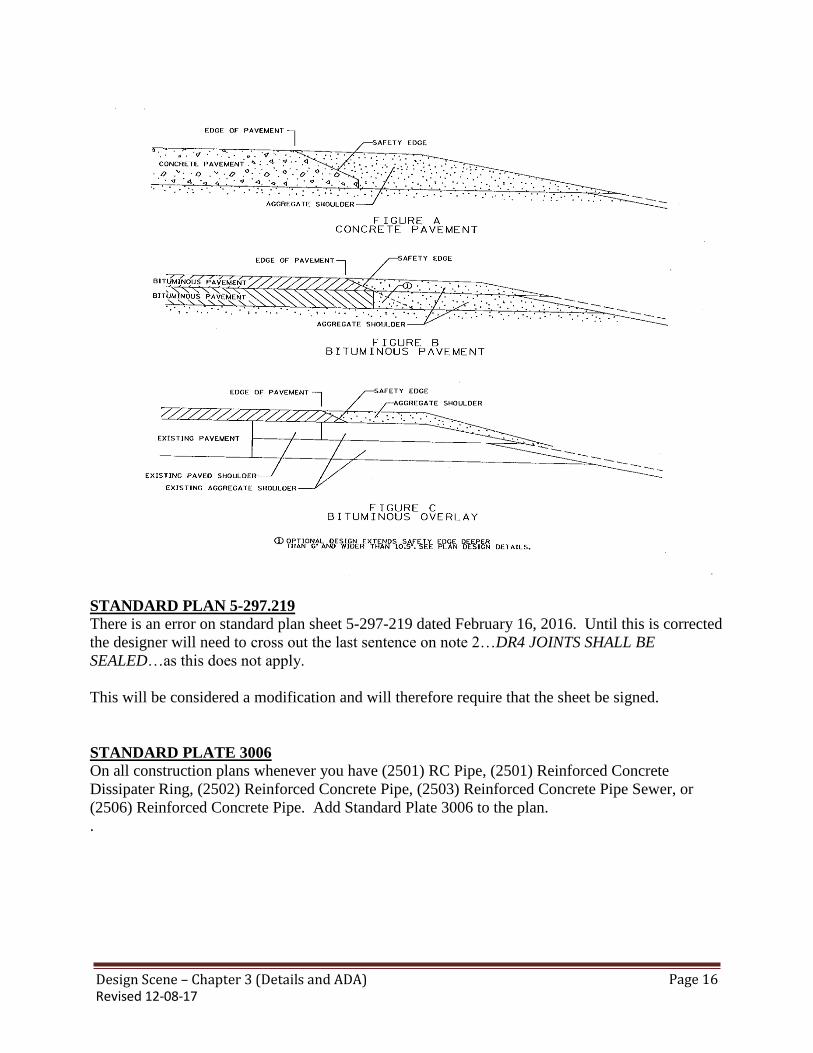
Design Scene – Chapter 3 (Details and ADA) Revised 12-08-17
Page 16
STANDARD PLAN 5-297.219 There is an error on standard plan sheet 5-297-219 dated February 16, 2016. Until this is corrected
the designer will need to cross out the last sentence on note 2…DR4 JOINTS SHALL BE
SEALED…as this does not apply.
This will be considered a modification and will therefore require that the sheet be signed.
STANDARD PLATE 3006
On all construction plans whenever you have (2501) RC Pipe, (2501) Reinforced Concrete
Dissipater Ring, (2502) Reinforced Concrete Pipe, (2503) Reinforced Concrete Pipe Sewer, or
(2506) Reinforced Concrete Pipe. Add Standard Plate 3006 to the plan. .

Design Scene – Chapter 4 (Earthwork and Soils & Construction Notes) Revised 12-08-17
Page 1
CHAPTER 4: EARTHWORK and
SOILS & CONSTRUCTION NOTES
2106 EARTHWORK PAY ITEMS
When using 2106 Earthwork pay items you cannot show any topsoil quantities. However, these
quantities still need to be supplied to the central office estimating unit.
Do NOT mix 2105 and 2106 pay items unless they are special 2105 items not covered by 2106.
2411 & 2451 STRUCTURE EXCAVATION CLASS Whenever 2411 & 2451 STRUCTURE EXCAVATION CLASS __ is included for structure
excavation a note should be added stating something like…THIS MATERIAL MAY NOT BE
SUITABLE AS EMBANKMENT AND SHALL BE DISPOSED OF BY THE CONTRACTOR
OFF THE PROJECT RIGHT OF WAY…or…IS SUITABLE AS EMBANKMENT
MATERIAL….which ever applies to the projects situation.
BITUMINOUS REMOVAL
The practice of removing 6” or less of bituminous pavement and paying for it with the common
excavation pay item has been discontinued and is not allowed under the current specification.
BRIDGE APPROACH TREATMENTS
A reminder to designers that we should pay for the select granular material used for bridge
approach treatments as detailed and noted on the standard plan sheets. This material is paid for as:
2105.507 SELECT GRANULAR BORROW ( ) CU YD and
2105.507 SELECT GRANULAR BORROW MOD 10% ( ) CU YD
2106.507 SELECT GRANULAR BORROW ( ) CU YD and
2106.507 SELECT GRANULAR BORROW MOD 10% ( ) CU YD
( ) = LV, CV, or EV
*If the modified borrow is used it should be noted in the estimated quantities what the
modification consists of.
CHECK EARTHWORK QUANTITIES
Please ensure earthwork design calculations are checked carefully. We have paid large claims due
to plan errors in the earthwork calculations. Make sure all areas are covered, the most common
area of error is muck excavation.
Check a few key areas by hand to confirm that the computer calculations are correct. Make sure
that the areas in Geopac are labeled correctly.
Design Scene – Chapter 4 (Earthwork and Soils & Construction Notes) Revised 12-08-17
Page 2
CONSTRUCTION NOTES Pertinent construction notes should be shown in the plan whenever possible, rather than included
in the special provisions. This makes it clearer and easier for the contractors bidding the job, as
well as for our engineers, inspectors, etc. It is better to have as much information as possible
shown in one document rather than having to refer to two of them, and the pertinent information is
less likely to be overlooked while bidding the project or constructing it in the field.
EXCESS MATERIAL
The special provision recommendations governing disposal of waste materials and/or surplus
excavated materials off the right of way are quite inconsistent. Some districts submit
recommendations that cover such disposal vary comprehensively, while others are extremely
vague.
Since protection of the environment, such as wetlands, has become so vital, we feel that standard
comprehensive provisions should be established and used on all projects, state-wide, where
disposal of materials off the right of way is required.
It is recommended to use the note…ALL MATERIAL NOT UTILIZED ON THIS PROJECT
SHALL BECOME THE PROPERTY OF THE CONTRACTOR AND DISPOSED OF OFF THE
R/W IN ACCORDANCE WITH SPEC 2104.
NRHP-ELIGIBLE HISTORIC ROADSIDE PROPERTIES
It is recommended that designers use the following note in construction plans when their projects
are located near NRHP-eligible historic roadside properties:
“Historic monument (Reference point XXX +XX.XXX) is eligible for the National Register of
Historic Places. Absolutely no construction staging, mobilization, material storage, construction
vehicle parking, or construction-related activities of any kind to take place within 120 feet of the
historic monument.”
PIPE JACKING When there is pipe jacking in the plan be sure to take into account how to handle the
storage/placement of the excavated material from the jacking pit. If not sure what this should be
assume for a 12” to 96” diameter pipe:
Width = 3 times the pipe diameter
Length = 2 times the pit width
For larger pipe sizes, or box culverts, you would need larger or specially designed pits and should
contact the district hydraulics office for assistance. If the soils are particularly bad in an area, your
pit width, and possibly length would also be greater because you would need a larger backing area
to push against.

Design Scene – Chapter 4 (Earthwork and Soils & Construction Notes) Revised 12-08-17
Page 3
PIT DATA
Gravel pits shown in the plans as possible sources of natural materials are causing some problems
and delays in the processing of plans and special provisions for bid-letting. In many instances pits
are listed in the plans with expired leases and other pits where leases are being negotiated. Gravel
pits should not be shown in the plans unless there is current lease to cover the approximate
contract time.
In the past, several projects had to be pulled from the letting because the contractor had obtained
an exclusive right to the granular source. This results in unfair competition and/or high bid prices.
If the designer has information or suspects that there will only be 1 source of material, he should
contact the Right of Way people so the state can get a lease for the pit. The District Materials
Engineer or the Aggregate Engineer should be able to assist the designer in determining if there is
a chance that a contractor can tie up the only source of material.
To alleviate these problems, it is suggested that the designer, six to nine months prior to the letting,
notify the District R/W Engineer of the gravel pits that will be listed for the project. This would
allow them time to check the lease and other necessary pit information. The designer should
submit this information to the Special Provisions Engineer at the time the plan is submitted. This
information should consist of the following:
Pit Number
Indicate if the pit is State owned or has an exclusive lease or nonexclusive lease.
Lease expiration date.
Current price of materials in cubic yards, cubic yards compacted volume and ton.
Any special conditions of the lease that may affect the contract or contractor.
Pit data may be shown on one of the first three (3) sheet of the plans. If it is shown farther back in
the plan it makes it difficult to find, and the necessary pit information may not be include in the
special provisions for the project and may require an addendum to correct.
SUBGRADE EXCAVATION If it is the intent of the project to pay for the subgrade excavation as part of the common
excavation a note should be included in either the soils notes, estimated quantity table, or tab
sheet. It should state something like…”All excavation shall be paid for as excavation-common.”

Design Scene – Chapter 5 (Utilities) Revised 12-08-17
Page 11
CHAPTER 5: UTILITIES
GENERAL UTILITY INFORMATION
Experience shows that proactive utility coordination early in the design of a project minimizes the
amount of effort needed later in the design life and during construction. It also helps the state avoid
costly unexpected problems and claims. MnDOT has developed a 14-step utility coordination
process that emphasizes communication among all parties involved. This process is outlined in
detail in the MnDOT Utility Accommodation and Coordination Manual, which is available online at:
www.dot.state.mn.us … MnDOT A to Z…U…Utility Relocation…In the chapter for “Utility
coordination process” click on the link for the “Utility Accommodation and Coordination Manual”
Many federal and state laws, rules, and regulations govern how the state handles utilities on its
projects. They are listed below.
Federal Laws
23 USC 109(I)
23 USC 123
Federal Regulations
Part 645 of title 23 of Code of Federal Regulations
Federal Guidelines
Program Guide: Utility Adjustments and Accommodations on Federal Aid
Highway Projects, Sixth Edition, January 2003, FHWA-IF-03-014
Highway/Utility Guide, June 1993, FHWA-SA-93-049
Minnesota State Constitution
Article 1, section 13
Article 14, section 2
Minnesota Statutes
Section 161.20, subdivision 1
Section 161.45
Section 161.46
Section 222.37, subdivision 2
Section 216D.04
Minnesota Rules
Parts 8810.3100 through 8810.3600
The “Laws, Rules, and Regulations” section on pages 8 through 9 of the Coordination Section of the
Utility Accommodation and Coordination Manual briefly describes each of these items
MnDOT’S 14-STEP UTILITY COORDINATION PROCESS
A brief overview of the 14-step utility coordination process is described below.
Step 1: Utility Identification
Find utility owners the project may affect by contacting Gopher State One Call and using any other
methods available (e.g., historical permits, old plans, etc.). Send the Utility Identification Letters to
Design Scene – Chapter 5 (Utilities) Revised 12-08-17
Page 11
those utility owners who do not reply to the Gopher State One Call request.
Step 2: Utility Information Meeting
Send the Utility Information Meeting Letter to the utility owners. Prepare for, hold, and follow up
on the Utility Information Meeting. Request information from the utility owners.
Step 3: Review of Information from Utility Owners
Receive and review information that the utility owners provide. Contact them about any errors or
inaccuracies.
Step 4: Utility Design Meeting
Send the Utility Design Meeting Letter to the utility owners. Prepare for, hold, and follow up on the
Utility Design Meeting.
Step 5: Request for Utility Relocation Plans
Request detailed relocation plans and schedules from the utility owners.
Step 6: Utility Coordination Follow Up
Review the relocation plans and schedules and follow up with the utility owners if there are any
questions.
Step 7: Utility Design Change Meeting (optional)
The Utility Design Change Meeting is only necessary when there is a major change to the design of
the project that will affect utilities. Prepare for, hold, and follow up on the Utility Design Change
Meeting.
Step 8: Gopher State One Call Verification
Contact Gopher State One Call no more than 90 days before plan submittal to see if there have been
any changes or additions to existing utilities.
Step 9: Review of Utility Relocation Plans, Schedule and Permit Submittal
Review the relocation plan, schedule, and permit application with Construction.
Step 10: Reimbursement and Utility Agreements (if necessary)
FYI…The Utility Agreements and Permits Unit performs this step when there are utility agreements
on a project.
Step 11: Notice and Order and Utility Relocation Permit
FYI…The Utility Agreements and Permits Unit issues Notice and Orders and handles long-form
permit applications.
Step 12: Utility Information in Contract Documents
Include all utility information in the request for bids.
Step 13: Construction
Construction coordinates any actual relocation in the field.

Design Scene – Chapter 5 (Utilities) Revised 12-08-17
Page 11
Step 14: Close Out (if necessary)
FYI…The Utility Agreements and Permits Unit closes out any utility agreements.
ABBREVIATED UTILITY COORDINATION PROCESS
The state requires the districts to use the full, 14-step utility coordination process on all projects,
with a few exceptions. Projects that may qualify for the abbreviated process include those that:
Have a timeframe less than 12 months;
Are stand-alone bridge replacement, removal, renovation, and repair projects;
Have no new right of way;
Are mill and overlay projects;
Require excavation but the exact location of excavation is determined in the field; and
Require excavation for work with little latitude for adjustment in the field.
Refer to the “Project Categories for Abbreviated Process Application” on pages 82 through 84 of the
Utility Coordination section of the Utility Accommodation and Coordination Manual for more
information about these projects and which steps you can eliminate from the process.
DEPICTING UTILITY FACILITIES ON PLANS
State law dictates how we must address utilities on our construction plans. If any required utility
information is missing, the state is responsible for the costs for any damages to facilities or
disruptions of service.
Although it is best to have separate utility sheets, you can include utility information on other plan
sheets if necessary.
General Requirements
If there is a petroleum or high-pressure gas line in the vicinity of the project, include a warning
note on the title sheet of the plan. (e.g. WARNING! PETROLEUM PIPELINE CROSSING)
Ensure that the names of the utility owners on the plan sheets are the correct, legal names of
those companies or agencies. Refer to the contact list on the Utilities website, for the most
current names. Do NOT include contact names, phone numbers and/or e-mail addresses.
Include the utility quality level note:
The subsurface utility information in this plan is utility quality level ___. This utility quality
level was determined according to the guidelines of CI/ASCE 38-02, entitled, “Standard
Guidelines for the Collection and Depiction of Existing Subsurface Utility Data.” This not must
be included in the plan whether utilities are affected or not.
State whether electric facilities are transmission or distribution. Include the voltages of all power
lines that are 69 kV or more.
Utility Tabulations
Typically ALL utility facilities that appear on the plan sheets are also shown tabulation form. Do
not duplicate facilities in the plan sheets. Do not tab facilities that are too far away to appear on the
plan sheets.

Design Scene – Chapter 5 (Utilities) Revised 12-08-17
Page 11
A sample of a utility tabulation is shown below.
Station Location In-Place Facility
Action
Utility Owner Leave As Is Adjust Relocate
1+00 to 2+00 3 ft RT to 10 ft RT buried telephone X Qwest Corp
2+00 to 3+00 10 ft RT to 9 ft RT buried telephone X Qwest Corp
3+00 9 ft RT telephone pedestal X Qwest Corp
If you have a long project but will only affect utilities in specific locations, only show and tab
utilities in those specific locations. For example, if you have a ten-mile mill and overlay project
with two culvert replacements, provide plan views of the culvert replacements that show the utility
facilities and tabulate those facilities. If there are other utility owners that have facilities in the
project limits but not in the vicinity of the specific work, include the following statement and list the
names of the utility owners:
The following utility owners have facilities within the limits of the project but will not be
affected.
If you check “ADJUST” for a utility action, you must define what adjust means (e.g. protect, lower
in-place, etc.).
As an alternative to showing the in a utility tabulation format would be to show the utilities only
within the plan sheets. Information that will be required would include the ownership of the facility
and a graphical representation of the areas where a utility conflict occurs along with the required
action (e.g. relocate or adjust). If using “ADJUST” a description of what needs to be done needs to
be provide. This method may not be appropriate in urban areas with many utilities.
An example of showing utility conflicts graphically instead of through tabulations is below:

Design Scene – Chapter 5 (Utilities) Revised 12-08-17
Page 11
No Affected Utilities
If there are no utility facilities in the project limits, include the utility quality level note and the
following sentence:
There are no utility facilities within the project limits.
If utility facilities are present but the project will not affect them, tabulations are not necessary. In
those cases, in addition to the information provided in the General Requirements section above, use
one of the following notes or something similar in the plan:
No utilities are affected by this project.
This project does not include excavation; therefore no utilities will be affected.
The utilities on this project are located outside the limits of excavation and will not be affected.
In addition to one of the statements above, include following language followed by a list of the
utility owner names:
The following utility owners have facilities inside the limits of the project.
Left In-Place Out-of-Service vs. Abandoned
On occasion, utility owners will stop using certain facilities without removing them from the right of
way. If you have a project where this is going to happen, make sure you use the correct term to
describe the situation. In general, you should use the phrase “Leave In-Place Out-of-Service” for the
affected facilities. This language tells the utility owner that it will retain ownership and
responsibility, and therefore liability for the facilities. The term “Abandon,” however, turns
responsibility and liability of the facilities over to the state.

Design Scene – Chapter 5 (Utilities) Revised 12-08-17
Page 11
Utility Locations and Elevations
Show the location of all utility facilities on the plan, profile, and cross section sheets of the plan.
Appendix M of the Utilities Manual shows the standard symbols to use to represent each facility.
If you do not know the depth of underground facilities, use the following assumptions on the cross-
section sheets:
Telecommunications: 3.0 feet below the surface;
Gas: 3.0 feet below the surface;
Electric: 3.5 feet below the surface; and
Water: 7.5 feet below the surface.
UTILITY AGREEMENTS AND PERMITS UNIT The Utilities Unit sends a copy of the plan to all of the utility owners listed. They must send a
Notice and Order to ALL utility owners that need to adjust or relocate their facilities because of our
construction, whether there will be an agreement or not. The Utilities Engineer makes the final
decision about whether utility work is reimbursable, so always check before making promises to
utility owners. There are three situations in which the state MAY reimburse utility owners.
The utility owner must relocate facilities from a location on which it has a property right, such as
an easement.
The relocation meets the requirements of a municipality’s first move.
The project is on interstate right of way.
Agency agreements are receivable agreements that are required when MnDOT’s contractor will be
placing, adjusting, or relocating utilities as part of the construction contract. A bridge attachment is
the most common type of work covered by an agency agreement.
MUNICAPAL UTILITIES When constructing a trunk highway project, MnDOT frequently encounters utility facilities owned
by local units of government. These facilities include, but are not limited to: Sanitary sewer systems and their related appurtenances; Water mains and their associated hydrants, gate valves, and manholes; and Street lighting facilities.
While MnDOT often designs street lighting facilities, it considers the design of sanitary sewer and
water main systems to be outside its area of expertise. This memo clarifies and provides guidance
for dealing with sanitary sewer and water main systems affected by MnDOT construction projects.
Construction projects often make the relocation or adjustment of utility facilities necessary. Any
party performing such relocation or adjustment work must do so pursuant to the MnDOT Utility
Accommodation on Highway Right of Way Policy and the Utility Accommodation and Coordination
Manual.
Minnesota Statutes, section 161.45, subdivision 2 allows a utility owner to appoint MnDOT as its
agent to design and construct utility work as part of a state construction contract. MnDOT includes

Design Scene – Chapter 5 (Utilities) Revised 12-08-17
Page 11
utility adjustment or relocation work in its contracts in cases where performing the work separately
would be too difficult or expensive for the utility owner or would be too disruptive to the operations
of the roadway (e.g., a relocation that would require digging up the road the contractor is building).
Minnesota Statutes, section 161.45, “Utility on Highway Right-of-Way, Relocation;” Minnesota
Statutes, section 161.46, “Reimbursement of Utility;” and Minnesota Administrative Rules
8810.3100 – 8810.3600, “Utilities and Equipment” determine which party is responsible for the
costs associated with relocating or adjusting a utility owner’s facilities as part of a MnDOT project.
The Utilities Engineer provides the final determination on cost responsibility. For work included in a
MnDOT construction contract, MnDOT is required to either execute a utility agreement or a
cooperative construction agreement with that agency. The agreement details the cost responsibility,
terms and conditions of the utility work.
If MnDOT includes a municipality’s sanitary sewer or water main work in its construction contract,
MnDOT and its consultants may not design those facilities; therefore, the municipality or its
engineering consultant must perform the design engineering work. This is the case regardless of
who is responsible for the cost of the relocation. If a consultant under the MnDOT contract is
willing to perform the sanitary sewer or water main design, that consultant must enter into a separate
contract with that municipality. The municipality is required to indemnify and certify any plans that
will become part of MnDOT’s project.
MnDOT may include minor modifications to the sewer and water facilities in its plans without
detailed design sheets. Minor modifications include, but are not limited to, adjusting castings and
valve boxes, vertically adjusting hydrants (but not horizontally adjusting them), and removing out-
of-service facilities.
UTILITIES – BUY AMERICA
Description and Application
Buy America is the requirement that all iron and steel products that will be permanently incorporated
into a project having Federal-Aid participation are manufactured domestically. The requirements for
Buy America are found in 23 USC 313 and 23 CFR 635.410. Additional information can be found
here: “FHWA Program Policy & Guidance Center Buy America”. These requirements do not apply
to products that do not contain iron or steel. NOTE: This is not the same as Buy American. Buy
American applies to Federal procurement contracts per 41 USC 10a-10d and 48 CFR 25 (see here
for more information).
The Buy America statute (23 U.S.C. 313) has been around for several years, but section 1518 of
MAP-21 amended its scope in 2012. The statute now includes all contracts eligible for assistance
under title 23 within the scope of a finding, determination, or a decision under the National
Environmental Policy Act (NEPA), regardless of the funding source, if at least one contract within
the scope of the same NEPA document uses federal funds. In this case, the term “project” includes
all contracts covered by one environmental document. For example, the Saint Croix bridge crossing
is considered one project, so all iron and steel components on the SPs that fall under it, even if they
are not federally funded, must be Buy America compliant.

Design Scene – Chapter 5 (Utilities) Revised 12-08-17
Page 11
According to the Buy America statute, all permanent steel and iron products and their coatings must
be domestic. All manufacturing processes, from the initial melting and mixing through the bending
and coating stages, must occur in the United States. If a product leaves the US for any process, it
will become a foreign product. The minimal use criteria of the act allows a contractor to use foreign
products if the cost of those steel or iron products is no more than 0.1 percent of the total contract
cost or $2,500 (whichever is greater). In order to use to use steel or iron components that cost more
than this amount, the contractor must apply for and receive an approved waiver through the Regional
Administrator of the FHWA.
Basically, any phase of any project involving any amount of federal funds must meet Buy America
requirements. For example, if you have a contract for signal installation that is part of a larger
project that will receive federal reimbursement, all steel signal poles must be Buy America
compliant, even if the federal funds are very small.
Manufacturing is any process that modifies the chemical content; physical shape or size’ or final
finish of the product.
This includes:
Initial melting, bending, drilling, machining, etc.
Application of coatings applied to iron or steel.
Components within applied coatings.
This does not include:
Materials/products shipped overseas for assembly prior to incorporation.
Buy America applies to all steel and iron materials/products, components and sub-components, and
hardware necessary to encase, assemble, and construct steel components (e.g. reinforced concrete
pipe, permanent sheet pile, truncated domes, catch basin grates, etc.).
If iron or steel products are shipped overseas for any of the reasons in the “includes” section above,
it will be considered non-domestic and will not comply with Buy America requirements.
Scope
Buy America is applicable for all projects utilizing Federal Aid monies. In addition, the Moving
Ahead for Progress in the 21st Century (MAP-21) legislation placed new requirements for projects
(and contracts) that do not have Federal Aid, but do fall within the scope of a NEPA determination.
These types of projects include State Funded projects that are completed within a “phase” or “stage”
of the overall project but are let separately and also all utility relocations that are required as a result
of the overall construction defined within the NEPA determination. It should be noted that this
includes both public as well as private utilities.
Waivers
In select instances, project specific waivers may be approved by the Regional Administrator. These
should be done as early as possible and needs to be well justified. The information needed for this
request is as follows:
Federal- aid Project Number
Project Description
Project Cost

Design Scene – Chapter 5 (Utilities) Revised 12-08-17
Page 11
Waiver Item Cost
Country of Origin for the Product
Reason for the Waiver
Incorporation of Materials/Products
Materials and/or products that are to be permanently incorporated into a construction project will
need to have certification prior to incorporation. If an incorporated product or material is found to
be in non-conformance with Buy America, the entire Federal participation may be in risk for the
project (not just for the non-conforming materials).
Buy America only applies to permanent installations. Projects that only use state funds do not need
to comply with Buy America.
TRENCHING FOR UTILITIES There has been concern that consideration is not being taken for excavating for larger utility pipes.
Be sure to allow for enough area to excavate for the deeper/larger utilities.
ROUNDABOUTS AND UTILITY COORDINATION
MnDOT and local agencies are utilizing and incorporating roundabouts (RABs) more frequently into
their projects to improve the safety and traffic operations of their roadways. While MnDOT’s Utility
Accommodation and Coordination Manual does not address any section specifically as
“Roundabouts,” MnDOT’s policy on accommodating utilities on its trunk highway rights of way is
pretty clear.
From the Manual:
IV.A.1 – Location Requirements, General: “Utility facilities shall be located to minimize the need
for later adjustments to accommodate future highway improvements, minimize risks to trunk highway
and environmentally sensitive areas, and permit access for servicing such lines with a minimum of
interference to highway traffic.”
IV.D.1 – Location Requirements, Longitudinal Installations: “New longitudinal installations on
highways without full or partial access control shall be located on uniform alignment as near as
practicable to the right of way line and outside the clear zone. Pole lines shall normally be placed in
the outer five feet next to the right of way line. Underground facilities, should be parallel and adjacent
to these facilities. Other locations may be approved where particular circumstances warrant. The joint
use of pole lines is encouraged, as is common trenching or plowing of underground facilities to
minimize overcrowding of the right of way. The placement of all installations should allow servicing
and maintenance with a minimum disturbance to traffic.”
VIII.B.4 – Specific Requirements, Underground Utility Facilities, Longitudinal installations:
“Underground utility facilities may be placed longitudinally by and must be located on uniform
alignment as near as practical to the right of way line to provide a safe environment for traffic
operations, preserve the integrity of the highway, and preserve space for future highway improvements

Design Scene – Chapter 5 (Utilities) Revised 12-08-17
Page 11
or other utility facility installations. The distance from the right of way line will depend on the terrain
involved and obstructions such as trees and other existing underground or aerial utility lines.
Underground lines shall not be placed longitudinally beneath the median, beneath through traffic
roadways including shoulders, or beneath ditch bottoms.”
VIII.B.5 – Specific Requirements, Underground Utility Facilities, Crossings: “Underground utility
facilities placed longitudinally along a connecting roadway shall not be placed under the median or
beneath through traffic roadways, including shoulders, of the connecting roadway where the roadway
connects with a state highway.”
“Beneath through traffic roadways and including shoulders,” e.g. under pavement is not permitted.
Utilities are to be relocated away from RABs. New facilities are to “jog” around the RAB and not
pass through in continuation. Refer to the two diagrams below showing T and multi-leg intersections
at RABs.
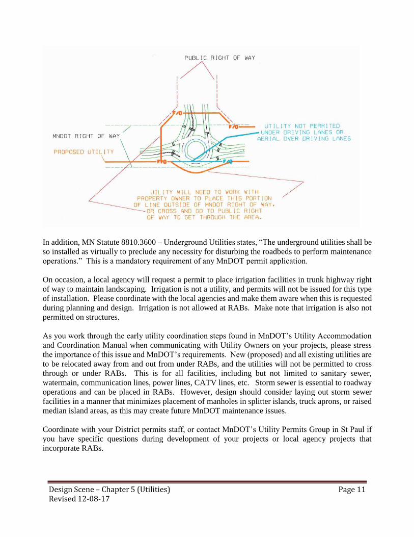
Design Scene – Chapter 5 (Utilities) Revised 12-08-17
Page 11
In addition, MN Statute 8810.3600 – Underground Utilities states, “The underground utilities shall be
so installed as virtually to preclude any necessity for disturbing the roadbeds to perform maintenance
operations.” This is a mandatory requirement of any MnDOT permit application.
On occasion, a local agency will request a permit to place irrigation facilities in trunk highway right
of way to maintain landscaping. Irrigation is not a utility, and permits will not be issued for this type
of installation. Please coordinate with the local agencies and make them aware when this is requested
during planning and design. Irrigation is not allowed at RABs. Make note that irrigation is also not
permitted on structures.
As you work through the early utility coordination steps found in MnDOT’s Utility Accommodation
and Coordination Manual when communicating with Utility Owners on your projects, please stress
the importance of this issue and MnDOT’s requirements. New (proposed) and all existing utilities are
to be relocated away from and out from under RABs, and the utilities will not be permitted to cross
through or under RABs. This is for all facilities, including but not limited to sanitary sewer,
watermain, communication lines, power lines, CATV lines, etc. Storm sewer is essential to roadway
operations and can be placed in RABs. However, design should consider laying out storm sewer
facilities in a manner that minimizes placement of manholes in splitter islands, truck aprons, or raised
median island areas, as this may create future MnDOT maintenance issues.
Coordinate with your District permits staff, or contact MnDOT’s Utility Permits Group in St Paul if
you have specific questions during development of your projects or local agency projects that
incorporate RABs.

Design Scene – Chapter 5 (Utilities) Revised 12-08-17
Page 11
UTILITIES NEAR FOUNDATIONS When working near bridge foundations be sure to check out the Bridge LRFD Manual regarding
utilities near foundations. Utility location restrictions occur within 50 feet laterally, 50 feet
below, and 15 feet above the base of spread footing foundations. Utility installations in this
region requires review and approval by the MnDOT Bridge Office. Additional restriction on the
locations of the utilities may be specified in other documents relevant to the project.
Design Scene – Chapter 6 (Staging and Bypass) Revised 12-08-17
Page 1
CHAPTER 6: STAGING and BYPASS TRAFFIC ON OPPOSING ROADWAY During staging the traffic is sometimes placed on the opposing traffic roadway on divided highways.
When this happens the guardrail end treatments and bridge connections need to be made safe. This
may require adding design specials, impact attenuators, and/or guardrail end treatments.
TEMPORARY CULVERT In the past there were occasions where the contractor would supply and install a temporary culvert
as in a bypass situation. Then the culvert would be salvaged and hauled to the district maintenance
facility.
This is no longer allowed. When a contractor is required to furnish and install a temporary culvert
it must be removed and become the property of the contractor or salvaged to be used elsewhere on
the project. It CANNOT be salvaged and hauled to the District.
TEMPORARY GUARDRAIL In the past there were occasions where the contractor would supply and install temporary guardrail
and/or end treatment as in a bypass situation. Then the guardrail and/or end treatment would be
salvaged and hauled to the district maintenance facility.
This is no longer allowed. When a contractor is required to Furnish and install temporary
guardrail/end treatment it must be removed and become the property of the contractor salvaged
to be used elsewhere on the project. It CANNOT be salvaged and hauled to the District.

Design Scene – Chapter 7 (Alignment) Revised 12-08-17
Page 1
CHAPTER 7: ALIGNMENT QUALITY MANAGEMENT
7.1 Description
Creation of an additional alignment file and a summary of the total lane miles per lift
(rounded to the nearest hundredth) for the given material type requiring compaction and/or paving
efforts (e.g., 2215 (SFDR), 2390 (CIR /CCPR), 2353, 2360, 2365) is required for jobs using (2016)
“Quality Management” and (2016) “Quality Management Special”. These specifications are
required on traffic and auxiliary lanes as defined in section 7.2 “Definitions”. Additionally, provide
the name of the county coordinate system used to generate the design files, as this information is
often requested by the Contractor.
A (2016) Quality Management Special – Intelligent Compaction (IC) Method
See Section 7.3 for details outlining the complex shapes and file formats that are required
with this special provision.
B (2016) Quality Management – Paver Mounted Thermal Profile (PMTP) Method
See Section 7.4 for details outlining the alignment file features and file formats that are
required with this special provision.
7.2 DEFINITIONS
A Auxiliary Lane—See MnDOT 1103 “Definitions”. (2016) Quality Management and
(2016) Quality Management Special is required only on continuous left turn lanes and passing lanes.
Exclude auxiliary lane tapers, ramps, shoulders, cross-loops, non-continuous turn lanes, loops,
bypass lanes, acceleration/deceleration lanes and intersecting streets.
B Driving Lane—See Traffic Lane.
C Intelligent Compaction—are compaction efforts completed by a self-propelled roller
integrated with a global navigation satellite system and onboard documentation system that can
display real-time color-coded maps of roller location, number of passes, roller speeds, and amplitude
and vibration frequencies of the roller drum. Some systems are also equipped with drum vibration
instrumentation, infrared temperature sensors, and/or Automatic Feedback Control. The onboard
documentation system on these rollers would also display real-time color-coded maps of stiffness
response or pavement surface temperatures, or both.
D Paver Mounted Infrared Temperature Equipment—this system continually monitors
the temperature of the mat immediately behind the paver screed during placement operations.
E Thru—See Traffic Lane.

Design Scene – Chapter 7 (Alignment) Revised 12-08-17
Page 2
F Traffic Lane—See MnDOT 1103 “Definitions”. (2016) Quality Management and
(2016) Quality Management Special is required on all traffic lanes with the exception of traffic lane
tapers and roundabouts (including the traffic lane between the roundabout and mainline transition
prior to and after the radius point of the roundabout).
G Veta—is a standardized intelligent construction data management (ICDM) software
that stores, maps and analyzes geospatial data resulting from intelligent compaction, thermal
profiling and Spot Test Data (e.g., density, moisture). This software can perform standardized data
processing, analysis and reporting to provide Project summary results quickly in the field from
various intelligent compaction and thermal profiling manufacturers. In particular, the software can
provide statistics, histograms, correlations for these measurements (e.g., speed, temperature, pass
count, ICMV), document coverage area and evaluate the uniformity of compaction as part of the
Project quality control operations. Veta can be downloaded from the Advanced Materials and
Technology Website
(http://www.dot.state.mn.us/materials/advancedmaterialsandtechnology.html).
7.3 BACKGROUND FILE: (2016) QUALITY MANAGEMENT SPECIAL –
INTELLIGENT COMPACTION (IC) METHOD
A General Information
(2016) Quality Management Special – Intelligent Compaction (IC) Method requires the
creation of background and alignment files created with closed complex shapes where the edges
of each Traffic Lane and Auxiliary Lane are closed at each end. Additionally, for projects
containing exceptions, create a complex shape for each traffic and auxiliary lane on each side
of the exception. The background and alignment files are imported into Veta to allow for more
detailed analyses with respect to given locations within the project limits and to allow for removal
of miscellaneous data that is not associated with the given compaction efforts. Additionally, these
background or alignment files are loaded on to the on-board display of each intelligent compaction
roller to allow the roller operator to visually see the line-work of the production area(s) with respect
to compaction efforts. This real-time view helps ensure that adequate and uniform compaction
efforts occur across the production area.
In addition to a complex shape, ensure that the in-place centerline, station text and
station tick marks are included in these files.
Save a copy of the background file in the following formats:
(1) 2D-DGN and 2D-KMZ Background File and
(2) LandXML Alignment File Section 7.3.B outlines the procedure for creating the complex shape(s) and the different
saving requirements.

Design Scene – Chapter 7 (Alignment) Revised 12-08-17
Page 3
The following instructional videos are available on the Advanced Materials and technology
Website (http://www.dot.state.mn.us/materials/amt/manualsguides&videos.html). Additional
instructional videos will be added as needed.
(1) Creating Background Closed complex Shape
(2) Converting Complex Shapes to a B-Spline Curve
(3) Exporting to KMZ for Google Earth
B CREATING A BACKGROUND FILE WITH A COMPLEX SHAPE AND
ALIGNMENT
(1) MICROSTATION FILE
(a) Copy a New Seed File
Copy the seed file to the project folder and rename to Functional Area SP_IC.dgn (e.g.
d3408023_IC.dgn).
(b) Assign the County Coordinate System
This will only need to be completed once per file, as it is saved in the File Settings.
(b1) Select Tools > Geographic > Select Geographic Coordinate System from
the MicroStation main menu.
(b2) If the County has already been defined it will be listed in the dialog. The
dialog will be blank if it has not been defined. See figure 7.1.
Figure 7.1. Snapshot of unassigned geographic coordinate system.
(b3) Click Select from Library (second icon from the left). While one can
navigate through the Library tab to find the county, it is easier to use the Search tab.

Design Scene – Chapter 7 (Alignment) Revised 12-08-17
Page 4
(b4) Enter the county into the Search Text and select Find Now (see figure 7.2).
As illustrated in figure 2, at least 3 lines for each county will appear. Select the US Foot option.
Click Add to Favorites if it is a county that is often used.
Figure 7.2. Snapshot of county coordinate search library.
(b5) Select OK to add the County to the Geographic Coordinate System dialog
and to close the Select dialog.
(b6) Review the Coordinate System (see figure 7.3), and if everything is correct,
close the dialog.
Figure 7.3. Snapshot of assigned geographic coordinate system.
(b7) Save these changes in MicroStation (File > Save Settings from the
MicroStation menu to save the County Coordinate System), otherwise, exiting and opening the file
again will lose the county coordinate system. Additionally, update the server copy to save in
ProjectWise.
(2) CLOSED COMPLEX SHAPE

Design Scene – Chapter 7 (Alignment) Revised 12-08-17
Page 5
(a) Load/import the roadway alignment in the SP_IC.DGN. Do not reference in
alignment file.
Only include Alignment Levels and User Defined Levels in this file (see figure 7.4).
Figure 7.4. Example of Alignment and User Defined Levels.
(b) If the alignment contains Spirals, replace the Spirals with Arcs, as Veta cannot read
the Spirals correctly (see figure 7.5). The horizontal position should be within 3 in (76 mm) when
replacing Spirals with an Arc.
Verify that the Spirals are removed during the creation of the Arcs.
Figure 7.5. MicroStation snapshot of Spiral locations replaced with Arcs.
(c) Creation of Complex Shape
(c1) Use the MicroStation drafting tool (e.g., Copy Parallel, Place Line, Create
Complex Shape) to create elements to make a closed complex shape, for each Traffic and
Auxiliary Lane, where the edges of the lanes are closed at each end.

Design Scene – Chapter 7 (Alignment) Revised 12-08-17
Page 6
(c2) Exclude all taper areas by ending the complex shape at beginning of the taper
where lane width begins to change.
(c2) Differentiate each Lane by using the user defined levels (UDEF [A, B, C, D,
etc.]) for associated shape(s) (see figure 7.6). Figures 7.7, 7.8 and 7.9 provide examples of common
complex shapes that are often needed.
Figure 7.6. Image of user defined levels.
Figure 7.7. Snapshot of two (2) complex shapes / lines for a 2-lane highway.
Complex Shapes / Lines Level: UDEFA
(WB, Driving Lane)
Complex Shapes / Lines Level: UDEFB
(EB, Driving Lane)

Design Scene – Chapter 7 (Alignment) Revised 12-08-17
Page 7
Figure 7.8. Snapshot of four (4) complex shapes / lines for a 4-lane, divided highway.
Complex Shapes / Lines Level: UDEFA
(WB, Driving Lane)
Complex Shapes / Lines Level: UDEFC
(EB, Passing Lane) Complex Shapes / Lines
Level: UDEFD (EB, Driving Lane)
Complex Shapes / Lines Level: UDEFB
(WB, Passing Lane)

Design Scene – Chapter 7 (Alignment) Revised 12-08-17
Page 8
Figure 7.9. Snapshot of three (3) complex shapes / lines for a 2-lane highway with an auxiliary
lane (continuous left turn lane).
(c3) Automatic Method – Maximum Gap Value
Increase the maximum gap value from the default value of 0.0100 ft to 0.1 ft when
using the Automatic Method (see figure 7.10). Overlaps and gaps on the outside edges of the shape
elements occur when the complex shape does not include all of the elements (e.g., for instances with
curve less PIs).
Figure 7.10. Image of selection screen for setting the maximum gap of the complex shape.
Complex Shapes / Lines Level: UDEFB
(EB, Driving Lane)
Complex Shapes / Lines Level: UDEFC
(Auxiliary Lane, Continuous Left Turn lane)
Complex Shapes / Lines Level: UDEFA
(WB, Driving Lane)

Design Scene – Chapter 7 (Alignment) Revised 12-08-17
Page 9
(c4) Projects with Exceptions
For projects containing exceptions, create a separate complex shape for each Traffic
and Auxiliary Lane on each side of the exception (see figure 7.11).
Figure 7.11. Snapshot of four (4) complex shapes / lines for an 2-lane highway with an
exception.
(c5) Lanes containing one or more exceptions are the only instance where there
is more than one element on a User Defined Level (see figure 7.12).
Complex Shapes / Lines Level: UDEFA
(WB, Driving Lane, West of Exception)
Complex Shapes / Lines Level: UDEFA
(WB, Driving Lane, East of Exception)
Complex Shapes / Lines Level: UDEFB
(EB, Driving Lane, West of Exception)
Complex Shapes / Lines Level: UDEFB
(EB, Driving Lane, East of Exception)

Design Scene – Chapter 7 (Alignment) Revised 12-08-17
Page 10
Figure 7.12. Example of lanes containing two (2) exceptions and the corresponding User
Defined Levels.
(c5) Variations in required Complex Shape Boundaries
Slight variations of the required boundaries for the closed complex shapes may
occur at the request of the Contractor. For instance, construction staging may be setup for grading
work to be completed across the entire embankment width, in lieu of constructing one lane at a time.
This would require the creation of one closed complex shape to include (enclose) all adjacent Traffic
and Auxiliary Lanes (see figure 7.13). Additionally, there may be instances for paving applications
where there is a continuous left turn lane and the Contractor paves 1.5 lanes (18-ft passes) instead
of each lane separately. This case would require the complex shapes to be created for 1.5 lanes, in
lieu of 3, separate 12-ft lanes (see figure 7.14).
More than one element on each User Defined Level.
Exceptions

Design Scene – Chapter 7 (Alignment) Revised 12-08-17
Page 11
Figure 7.13. Snapshot of one (1) complex shape / line containing adjacent Traffic Lanes.
Figure 7.14. Snapshot of complex shapes / lines for 18-ft paving (1.5 lanes).
(c6) Converting Complex Shapes to B-Spline Curve
Convert all complex shapes to a B-spline curve as follows (see figure 7.15):
Select Tools > Curves > Curve Utilities > Convert to b-spline curve
Complex Shapes / Lines Level: UDEFA
Complex Shapes / Lines
Level: UDEFA
Complex Shapes / Lines Level: UDEFB

Design Scene – Chapter 7 (Alignment) Revised 12-08-17
Page 12
Figure 7.15. Snapshot of converting complex shape to a b-spline curve.
(3) Google Earth File (KMZ)
Also save the design file as a KMZ (google earth) file. This file will be used with MnDOT’s
intelligent construction data management tool “Veta”.
(a) In the Background DGN, Turn off the weights, which are normally too heavy within
Google Earth (see figure 7.16).

Design Scene – Chapter 7 (Alignment) Revised 12-08-17
Page 13
Figure 7.16. Modification of line weights in MicroStation (Attributes).
(b) Set the view to the area of interest. Please note that the larger the area, the fuzzier
Google Earth is when using the zoom feature.
(c) Select Tools > Geographic > Export Google Earth (KML) File from the main
MicroStation menu. Or File > Export > Google Earth
(d) A dialog will open where one can name the Google Earth file.
Please note that it is creating a KMZ file, not KML as seen in the tool tip. Use the default
name if a KMZ file has not already been created from this MicroStation file. Otherwise, change the
name in order to save . Click Save.
(e) The following are some miscellaneous details related to the use of Google Earth.
(e1) Google Earth opens and moves to the location of the file. One will see the
Google Earth background, with the MicroStation drawing on top (see figure 7.17).
Figure 7.17. Snapshot of alignment file on google earth background.
(e2) If the MicroStation Elements appear dis-jointed or incomplete, toggle OFF
then ON the location in the Places area of the side bar. This will “refresh” the elements to allow
them to display properly.
(e3) Zoom in and out using the wheel on the mouse.
(e4) Pan by holding down the data point button on the mouse.
(e5) If the view is “drifting”, click a data point on the screen.
(e6) If the sidebar menu is not displayed, select View > Sidebar. Here one can
turn off/ on the levels in the MicroStation File (e.g., Street Names, etc).

Design Scene – Chapter 7 (Alignment) Revised 12-08-17
Page 14
(e7) To see the “videolog” tool, toggle on Street View” in the lower left section of
the sidebar (Layers section). Small cameras appear in the drawing. Click on one to open to Street
view. To get back to the Top view, click the design file in the Places section in the Sidebar menu.
7.4 BACKGROUND FILE: (2016) QUALITY MANAGEMENT – PAVER MOUNTED
THERMAL PROFILE (PMTP) METHOD
A General Information
(2016) Quality Management – Paver Mounted Thermal Profile Method requires the creation
of a background file. The background file is used to assist with determination of the monetary
price adjustment for thermal coverage and to assist construction personnel with locating areas with
medium to high levels of thermal segregation during the asphalt paving operation.
B Requirements
Use the background file generated for (2016) Quality Management Special – Intelligent
Compaction (IC) Method for projects where IC is also required. The IC background file can be used
for both (2016) Quality Management and (2016) Quality Management Special.
If IC is not required on the given project, the background file (at a minimum) must include
the centerline, station text, station tick marks and labeling for exceptions.
Save a copy of the background file in both a 2D-DGN and 2D-KMZ format.
See section 7.3.B(3) for instructions on how to save the file in a KMZ format.

Design Scene – Chapter 8 (Inplace Topography and Removals) Revised 12-08-17
Page 1
CHAPTER 8: INPLACE TOPOGRAPHY and REMOVALS
BUILDING REMOVALS In the past years it has been a requirement to have a separate building removal pay item (e.g.
Building Removal A, Building Removal B, etc.) for each parcel. It has been determined (from the
C.O. Land Management Office) that all parcels may be covered by one building removal pay item,
this would be Central Offices preference. Every building removal plan must include…
2103.501 BUILDING REMOVAL by LUMP SUM
However, the following items need to be covered by separate pay items per parcel on every building
removal plan.
2103.502 DISCONNECT SEWER SERVICE by EACH
2103.502 DISCONNECT WATER SERVICE by EACH
2103.507 BASEMENT EXCAVATION FILL By CU YD (add note…THE CONTRACTOR
SHALL PROVIDE AND RAKE IN GRASS SEED MIXTURE ??? AT A RATE OF ??? POUNDS
PER ACRE ON ALL DISTURBED AREAS (INCIDENTAL))
2104.502 REMOVE SEPTIC TANK by EACH (note if it includes the drain field or not)
2104.502 ABANDON & SEAL WELL SHAFT by EACH
2104.601 REGULATED WASTE EVALUATION by LUMP SUM or 2104.601 REMOVE
REGULATED WASTE MATERIAL by LUMP SUM (used for Asbestos, fluorescent bulbs, mercury switches, etc.)
2105.502 REMOVE UNDERGROUND TANK by EACH
2105.502 REMOVE ABOVEGROUND TANK by EACH
2573.503 SILT FENCE, TYPE MS by LIN FT
Also in the past standalone building removal plans were a process “A” plan. That is no longer the
case. Building removal plans involve utilities and therefore, are now designed as a process “B”
plan.
REMOVE BITUMINOUS PAVEMENT Whenever the pay item Remove Bituminous Pavement is used it should state somewhere in the plan
(either as a note or in the typicals) what the depth of the pavement removal is. This is to ensure that
all Contractors are bidding the project based on the same information.
REMOVE BITUMINOUS SHOULDER It has been brought to our attention that when bituminous shoulders are removed the remaining
aggregate shouldering material is not of sufficient quantity. We are advising that either an item (if
none exists) or additional quantity of shouldering aggregate be added to the plan to cover this
shortage.

Design Scene – Chapter 8 (Inplace Topography and Removals) Revised 12-08-17
Page 2
REMOVE CONCRETE PAVEMENT MnDOT settled a claim for the extra cost of removing reinforced concrete pavement. The contractor
claimed that since the plan did not state that the pavement to be removed was reinforced or
contained steel, his bid was based on removing non-reinforced pavement. Moreover, he proved that
on several other MnDOT projects that required removal of reinforced pavement, the plan indicated
the inplace pavement to be reinforced.
In order to prevent future claims and be consistent, designers should footnote the concrete pavement
removal item indicating the depth and type of reinforcing: mesh, rebars and/or dowel bars. If there
is no reinforcement, that should be noted too.
REMOVE PAVEMENT There has been considerable misunderstanding on when this pay item should be used. This item is
only used for cases where there is existing bituminous over existing concrete that is to be removed.
When this item is used it should state somewhere in the plan (either as a note or in the typicals) what
the depth of the bituminous pavement removal is as well as the depth of the concrete pavement
removal and if the concrete is reinforced or non-reinforced. This is to ensure that all Contractors are
bidding the project based on the same information
RIGHT-OF-WAY NOTE
It is recommended that the following note no longer be placed in the plans….
“The Right of Way shown in this plan gives a graphical location with respect to the geometric
design and map data. The exact right of way and boundary corners are located by references to the
right of way plats and are identified on the right of way map.”

Design Scene – Chapter 9 (Plan and Profile) Revised 05-09-16
Page 1
CHAPTER 9: PLAN and PROFILE
CROSSOVER DRAINAGE The designer needs to pay attention to the placement of the crossovers. They should not be placed
at the low point of the project and should be sloped to allow for drainage. It is encouraged to
include a profile in the plan for the crossover to ensure that drainage is accounted for.
LEGENDS
There has been some confusion on how legends should be shown on various sheets. There are three
acceptable options (in preferred order) for showing legends.
1. Sheet specific legend - The legend goes on every sheet and the information pertains only to
the sheet it is on.
2. General single legend - There is only one legend on the first sheet of a set of sheets that
covers all the information for that set of sheets. The legend either includes a note stating it
pertains to sheets x to xx, or each sheet references the legend on sheet x.
3. Generic legend on each sheet - Each sheet has EXACTLY the same legend on every sheet of
the set. If any of the legends has an extra item then they are no longer generic legends.
There has also been confusion as to where the legends need to be placed on the sheet. The
preference would be to locate the legend on the right side of the plan sheet. However, there are no
set criteria for where to place the legend as long as it is clear what it pertains to.
MEDIAN CROSSOVER/SIGNALIZED The following information is a first attempt at a solution. Neither the AASHTO Green book nor our
design manual give any guidance on this issue. The design of median crossovers at crossroads on
divided roadways has been a significant problem. Vehicles often “bottom out” when traversing the
crossovers at crossroad speeds.
Methods of flattening the median crossovers between the through lanes have had only limited
success in solving the problem. Other ideas have been suggested, such as sloping the inside through
lane up to match the slop on the outside through land and putting a high point in the middle of the
crossover. This has potential drawbacks for drainage and through traffic. As a compromise for now,
designers should use the following for median crossover design.
Transition the inside through lane to 0.005 ft./ft sloped down toward the median. Continue that
slope to the middle of the median crossover to intersect a similar slope from the other roadway. This
will reduce the rollover at the roadway crown and at the middle of the median crossover. Roadways
in superelevation should be designed so the profiles will allow slopes to be in the same direction all
the way across both roadways and the median crossover. This will help eliminate the “roller coaster”
effect.

Design Scene – Chapter 9 (Plan and Profile) Revised 05-09-16
Page 2
PLAN SHEETS Assure that all labeling is correct and present on the construction plan sheets. It should include, but
not be limited to…Begin/End SP’s, mainline, cross-streets, stationing, scales (bar scales only), north
arrows, Bridges (inplace and proposed) and equations (if not included on the general layout).
SPECIAL DITCH GRADES There has been some discussion on where special ditch grades should be computed to and shown in
the plans (bottom or top of topsoil). Engineers, inspectors and surveyors were consulted and the
general conclusion was that the designers should compute to and show the ditch grades to the
bottom of the slope dressing. A note should be placed in the plans explaining their location.

Design Scene – Chapter 10 (Paving) Revised 12-08-17
Page 1
CHAPTER 10: PAVING
AGGREGATE
Aggregate has become more specific on how it is paid for. Therefore, make sure the plan
specifies they type of aggregate to use.
Spec 2118 Aggregate Surfacing - Aggregate placed as shoulder or adjacent to
bituminous/concrete shoulder or mainline bituminous. This includes aggregate placed as
surfacing on entrances and road connections.
Spec 2211 Aggregate Base - to be used under mainline bituminous and can be used under
bituminous shoulders if placed at same time as mainline aggregate.
Spec 2221 Shoulder Base Aggregate -Aggregate placed under shoulder bituminous/concrete,
either as a different class or separate operation than mainline aggregate base.
AGGREGATE BEDDING
The current Spec Book has redefined aggregate bedding. Therefore, plans will no longer be using
2451 AGGREGATE BEDDING. This item is being replaced with one of three possible items…
Aggregate bedding has become more specific on how it is paid for. Therefore, make sure the plan
specifies they type of aggregate bedding.
2451.507 FINE AGGREGATE BEDDING (_V) by CU YD
2451.507 COARSE AGGREGATE BEDDING (_V) by CU YD
2451.507 CONDUIT AGGREGATE BEDDING (_V) by CU YD
Refer to page 548 of the 2016 Spec book or page 573 of the 2018 Spec book for material
specifications under 3149.2.G.
BITUMINOUS ITEMS IN PLANS The following is the recommended way to show Bituminous Items on the typical sections,
tabulations, and everywhere else they appear.
TYPICAL SHEET
2" Type SP 9.5 Wearing Course Mixture (SPWEA440E)
2" Type SP 12.5 Wearing Course Mixture (SPWEB440E)
2" Type SP 12.5 Non Wearing Course Mixture (SPNWB440B)
2" Type SP 19.0 Non Wearing Course Mixture (SPNWC440B)
Type SP 12.5 Wearing Course Mixture (SPWEB440A) 2” Thick
---------------------------------------------------------------------------------------------------------------

Design Scene – Chapter 10 (Paving) Revised 12-08-17
Page 2
TABULATION SHEET
Type SP 9.5 Wearing Course Type SP 9.5 Wearing Course
2” Thick
(SPWEA440E) (SPWEA440E)
NOTES
The patching mixture shall be Type SP 12.5 Wearing Course Mixture (SPWEB340B).
NOTE: All of the above are shown as examples only. The following are what the various letters
and numbers represent.
Mix Designations Mix designations for bituminous items are required in the plan whenever you reference the bituminous surface.
In terms of our normal spec. 2360 (plant mixed asphalt) mixture designation, here is a quick
summary. Example: (SPWEB340B)
The first two letters (SPWEB340B) represent the mix type…
SP = Superpave (really this just means that the asphalt mixture was designed using mixture
volumetrics with compaction being done in a gyratory mixer to determine the starting point for
mixture production. It is a result of research done nationally.)
SMA = Stone Matrix Asphalt, this is rarely used and follows spec 2365.
The third and fourth letters (SPWEB340B) represent the course…
WE = Wearing Course
NW = Non Wearing Course
The top 4 inches of mixture is normally WE and any mixture placed below that would be
NW. The local agencies have the cutoff at 3 inches.
The fifth letter (SPWEB340B) represents the aggregate size…
A = 1/2 inch, SP 9.5, our “A” aggregate size is 100% of the material passing the ½ inch sieve.
B = 3/4 inch, SP 12.5, Maximum aggregate size. Our normal aggregate size is 100% of the
material passing the ¾ inch sieve, which is classified as “B”.
C = 1 inch, SP 19.0, this is rarely used.
D = 3/8 inch, SP 4.75, this is rarely used.
The sixth digit (SPWEB340B) represents the traffic level…This number indicates the amount of
traffic the mixture is designed to carry in a 20 year period in millions of ESALs.
Traffic levels are as follows:
2 < 1 million ESALs
3 1 to < 3 million ESALs
4 3 to < 10 million ESALs
5 10 to < 30 million ESALs
6 is used with a different specification, 2365, Stone Matrix Asphalt (SMA).

Design Scene – Chapter 10 (Paving) Revised 12-08-17
Page 3
The last two digits (SPWEB340B) indicate the air void requirement:
40 = 4.0% for SP and Wear mixtures
30 = 3.0% for SP Non Wear and Shoulder and Local Agency (low volume) Wear
The letter at the end of the mixture designation identifies the asphalt binder grade. Designers/soils
engineers will start using a new binder grade system beginning January 1, 2016. The new grades
will be:
Old Grades New Grades
A = PG 52 34 A = PG 52S-34
B = PG 58 28 B = PG 58S-28
C = PG 58 34 C = PG 58H-34
E = PG 64 28 E = PG 58H-28
F = PG 64 34 F = PG 58V-34
L = PG 64 22 L = PG 64S-22
H = PG 70 28 H = PG 58V-28
There is a table in spec. 2360 (see Table 2360-2), basically a B letter means a PG 58-28 grade
asphalt binder will be used. In a very general sense, 58 = the maximum temperature (in °C) that
the binder will resist rutting, and – 28, is the temperature (in °C) that the binder will resist thermal
cracking. Different letter grades will change the top or bottom number.
COMPACTION OF BITUMINOUS MIXTURES Bituminous density requirements should not be placed in the construction notes or anywhere else within the plan.
The specification states that all pavements will be compacted in accordance with the Maximum Density Method unless otherwise specified in the Contract special provisions or as noted in
Section 2360.6C. Section 2360.6C is titled “Ordinary Compaction Method”.
CONCRETE JOINT PAY ITEMS There seems to be a number of people with questions on what joints to pay for on new concrete
pavement. The following is a brief explanation. The specification book gives the guidelines. We
encourage a tabulation on the plan which defines square yard quantities and cubic yard quantities
(as required).
We do not provide a separate pay item for the Longitudinal Expansion Joints, therefore,
longitudinal E1H joints do NOT need to be tabulated. However, show all of the E1H joints in the
concrete paving plan.
Payment for joints should be limited to the dowelled transverse expansion joints only, such as:
E2H-D, and E4H-D. The lineal foot measurement of 2301.503 Dowelled Expansion Joints,
Design ___, includes dowel bars, dowel bar assembly, expansion joint filler, and saw and sealing.

Design Scene – Chapter 10 (Paving) Revised 12-08-17
Page 4
CONCRETE OVERLAYS Concrete Overlay over existing concrete is called “Unbonded” Concrete Overlays. Because reflective cracking is likely to occur if bonding from the old to the new concrete pavement, a bond breaker (e.g. 2363 (PASSRC), 2360 (Plant Mixed Asphalt), 2105 (Geotextile Fabric), 2302 (Mill Bituminous Surface)) is placed between the inplace and newly placed concrete pavement. If the inplace concrete pavement had been previously overlayed with bituminous it is typically milled leaving 1 inch of bituminous remaining over the inplace concrete pavement. Concrete Overlay over an existing bituminous pavement is called “Whitetopping” or “Bonded Concrete Overlay (BCOA)”. Usually the bituminous is milled prior to the concrete pavement in order to remove deteriorated bituminous and more importantly to aid in the bonding of the concrete to the underlying bituminous. Contact the Concrete Engineering Unit when designing any of these types of projects for assistance in determining the special provisions and the language needed for surveying, paying for the bond breaker, the concrete, etc. See the “Roadway Profile for Concrete Overlays” for more information.
CONCRETE PAVEMENT REHABILITATION (CPR) The Concrete Rehabilitation Standards are available for downloading as boilerplates on the Concrete Office website at http://www.dot.state.mn.us/materials/concretepavementrehabilitation.html Special Provision Notes The special provisions have also been revised to reflect the changes to the CPR details.
CPR Pay Items The pay items for these have changed as well. The new pay items are….
Item No Description Unit
2301.602 Drill and Grout Reinforcement Bar (Epoxy Coated) Each
2302.602 Dowel Bar (1) Each
2302.602 Dowel Bar Retrofit Each
2302.603 Joint Repair (Type A1) Lin Ft
2302.603 Joint Repair (Type A2) Lin Ft
2302.603 Joint and Crack Repair (Type B3) Lin Ft
2302.603 Full Depth Repair (Type CA-LV) Lin Ft
2302.603 Full Depth Repair (Type CD-LV) Lin Ft
2302.603 Full Depth Repair (Type CD-HV) Lin Ft
2302.604 Pavement Replacement (Type CX) SQ YD
2302.604 Utility Trench Full Depth Repair (Type C2-LV) ONLY) SQ YD
2302.604 Concrete Grinding SQ YD
2302.604 Concrete Grinding Special SQ YD
2302.608
Supplemental Reinforcement Bars (Epoxy Coated) Pound
2302.618 Partial Depth Repair (Type BA) SQ FT
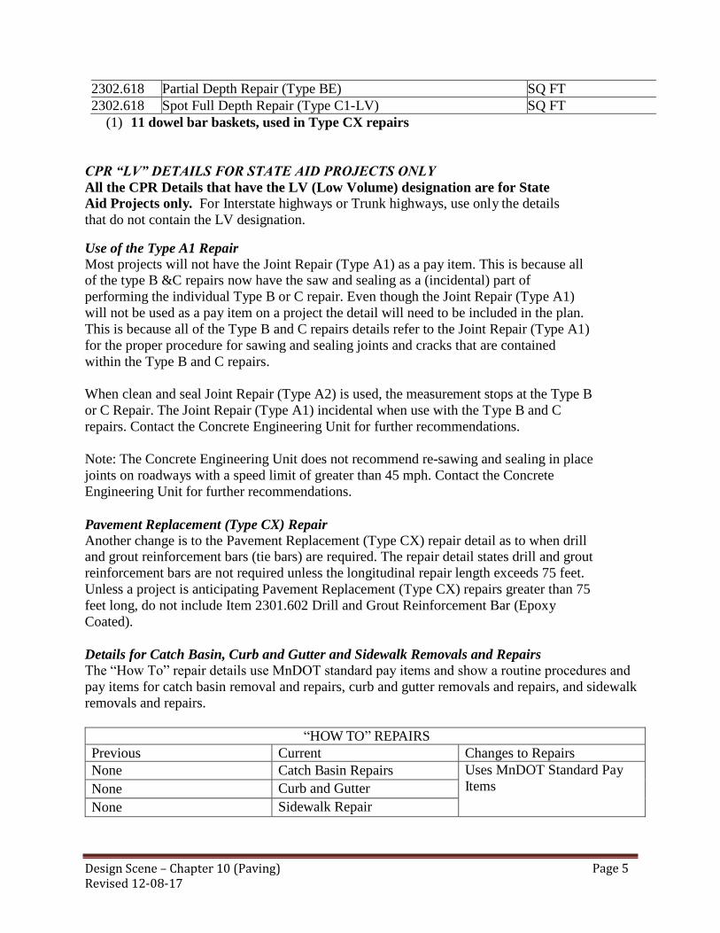
Design Scene – Chapter 10 (Paving) Revised 12-08-17
Page 5
2302.618
Partial Depth Repair (Type BE) SQ FT
2302.618 Spot Full Depth Repair (Type C1-LV) SQ FT
(1) 11 dowel bar baskets, used in Type CX repairs
CPR “LV” DETAILS FOR STATE AID PROJECTS ONLY
All the CPR Details that have the LV (Low Volume) designation are for State
Aid Projects only. For Interstate highways or Trunk highways, use only the details
that do not contain the LV designation. Use of the Type A1 Repair Most projects will not have the Joint Repair (Type A1) as a pay item. This is because all of the type B &C repairs now have the saw and sealing as a (incidental) part of
performing the individual Type B or C repair. Even though the Joint Repair (Type A1)
will not be used as a pay item on a project the detail will need to be included in the plan.
This is because all of the Type B and C repairs details refer to the Joint Repair (Type A1)
for the proper procedure for sawing and sealing joints and cracks that are contained
within the Type B and C repairs.
When clean and seal Joint Repair (Type A2) is used, the measurement stops at the Type B
or C Repair. The Joint Repair (Type A1) incidental when use with the Type B and C
repairs. Contact the Concrete Engineering Unit for further recommendations.
Note: The Concrete Engineering Unit does not recommend re-sawing and sealing in place
joints on roadways with a speed limit of greater than 45 mph. Contact the Concrete
Engineering Unit for further recommendations.
Pavement Replacement (Type CX) Repair Another change is to the Pavement Replacement (Type CX) repair detail as to when drill and grout reinforcement bars (tie bars) are required. The repair detail states drill and grout
reinforcement bars are not required unless the longitudinal repair length exceeds 75 feet.
Unless a project is anticipating Pavement Replacement (Type CX) repairs greater than 75
feet long, do not include Item 2301.602 Drill and Grout Reinforcement Bar (Epoxy
Coated).
Details for Catch Basin, Curb and Gutter and Sidewalk Removals and Repairs The “How To” repair details use MnDOT standard pay items and show a routine procedures and
pay items for catch basin removal and repairs, curb and gutter removals and repairs, and sidewalk
removals and repairs.
“HOW TO” REPAIRS
Previous Current Changes to Repairs
None Catch Basin Repairs Uses MnDOT Standard Pay
Items None Curb and Gutter
None Sidewalk Repair

Design Scene – Chapter 10 (Paving) Revised 12-08-17
Page 6
Time and Traffic Considerations Because of the ambient temperature requirements, consideration should be given to the time of
year the CPR project is to take place. If Table 2302-1 is to be used, do not schedule a CPR
project with an early start or will extend late into the construction season, after 10/15/XX.
These provisions do not cover anticipated minimum times to opening of less than 12 hours,
also known as ultra-high early concrete (UHE.) Ultra-high early concrete (UHE) is defined
as repair concrete that will have construction or general traffic place on the concrete repairs with
under 12 hours of cure time. Ultra-high early concrete projects require additional concrete
testing, a test pour, and other requirements that are not in the published 2302 special provisions.
When designing a project and the Engineer determines that the pavement repairs will
need to be opened to traffic in less than 12 hours – DO NOT use the standard CPR special
provisions. Contact the Concrete Engineering unit for the correct special provisions and
further recommendations on projects with anticipated opening times with less than 12
hours cure time.
For further clarifications or for CPR recommendations contact the Concrete Engineering
Unit.
CONCRETE PAVING PLAN JOINT LAYOUT SHEETS
The Concrete Engineering Unit recommends creating paving plan joint layout sheets. Remove
topography and other information not necessary for the actual concrete pavement construction.
The Concrete Engineering Unit also recommends including the longitudinal joint designations on
the Typical Sections if practical. If the Designer decides not to create separate paving plan joint
layout sheets, but does have specific joint layout desires, include a single joint layout sheet that is
typical of the project. Include the pavement lane widths, excluding curb and gutter that is placed
in a separate operation.
Contact the Concrete Engineering Unit with question regarding preparation and review of joint
layouts.
CONCRETE PAY ITEMS (Not Alternate Bid)
The following table should aid in selection of which pay items are needed whenever there is any
concrete pavement pay items except bridge approach panels and concrete pavement rehabilitation
on the job.
Method A: Pavement Constructed on Aggregate Base
Utilize Method A when, the longitudinal roadway profile has been established in the plan
and the concrete pavement is placed on a shaped & compacted aggregate base. Such as
new construction/grading projects in which the in place pavement is removed.
Method B: Pavement Placed on Bond Breakers
Utilize Method B when prior to the construction of the concrete pavement, a bond

Design Scene – Chapter 10 (Paving) Revised 12-08-17
Page 7
breaker layer is placed or a milled bituminous surface remains. For either case (bond
breaker or milled surface), the concrete pavement will likely have cross slope
corrections (variable cross-sectional concrete thickness) and a post letting revised
longitudinal profile. Because the final quantity will be revised, do not make pay item
2301.511 Structural Concrete a plan (P) quantity.
Pavement Reinforcement
Supplemental Pavement Reinforcement is placed at mid-depth of the concrete
pavement. Supplemental pavement reinforcement item is used when the concrete
pavement is constructed over excavated underground utilities (culverts, storm sewers,
water mains, etc.). Previously placed underground utilities usually do not require
Supplemental Pavement Reinforcement unless; settlement is an ongoing issue (a dip in
the roadway over an underground utility).
Reinforcement Bars shown on the Standard Plan Sheets are incidental: The Engineer
will not separately measure keyway bars (L2KT), tie bars (L1T), taper steel (gores< 6’
wide), and stopper bars (used at the discontinuation of a longitudinal joint).
Dowel Bars remain a pay item and are paid by the each.
Pay Item Selection for Concrete Paving Projects (Not Alternate Bid)
Item No. Description Unit Method A Method B
2301.502 Dowel Bar Each Maybe Maybe
2301.503 Dowelled Expansion Joints,
Design ___ linear foot Not likely Not likely
2301.503 Integrant Curb, Design ___ linear foot Maybe Maybe
2301.504 Concrete Pavement ___ in square yard Yes No
2301.504 Concrete Pavement ___ in High-Early square yard Maybe No
2301.504 Place Concrete Pavement ___ in square yard No Yes
2301.507 Structural Concrete cubic yard No Yes
2301.507 Structural Concrete High-Early cubic yard No Maybe
2301.508 Supplemental Pavement Reinforcement pound Maybe Maybe
DIAMOND GRINDING
A Boiler plate Special Provision (1717 Air, Land, and Water Pollution for Concrete Grinding) is
completed for this operation and must be included in the special provisions for BOTH 92302)
CPR and (2301) Concrete Paving projects. State law allows concrete grinding slurry to be placed
within MnDOT Right of Way, in accordance with Special Provision (1717 Air, Land, and Water
Pollution for Concrete Grinding) Special Provision 1717 outlines both areas were slurry can be
place and areas were slurry cannot be place with in MnDOT Right-of-Way. Special Provision
1717 requires Areas of Environmental Sensitivity (areas that require slurry collection and
disposal off the Right-of-Way) be identified on the plan set.

Design Scene – Chapter 10 (Paving) Revised 12-08-17
Page 8
The plans must show federally recognized tribal reservation boundaries. Identification of federally
recognized tribal reservation boundaries may be found on the following website:
http://mn.gov/indianaffairs/tribes.html.
All Areas of Environmental Sensitivity (AES) must be shown in the plans. Areas of
Environmental Sensitivity are as follows:
MnDNR Public Waters Inventory (PWI).
National Wetland Inventory (NWI).
Calcareous fens.
Permanent vegetation designated for preservation, such as areas adjacent to the right of way
identified as a ‘Site of Biodiversity Significance’ or ‘Native Plant Community’ by the DNR
Minnesota Biological Survey (MBS).
Prairie remnants, including but not limited to areas adjacent to Railroad Rights-of-way
Prairies.
Wooded areas with specimen trees.
Locations with Federal or State listed Threatened or Endangered plant species.
Locations with Federal or State listed Threatened or Endangered aquatic species.
Historic properties.
For identification of items 1- 5, the following web link will provide the needed information:
http://deli.dnr.state.mn.us/data_search.html
For identification of items 6-9 information and direction will be provided by the Office of
Environmental Stewardship (OES) staff through the project’s Early Notification Memo (ENM)
process.
In addition to the AES locations the following must also be identified on the plans:
Curb and gutter sections that convey storm water to catch basin inlets into a closed drainage
system (storm sewers).
Inlet structures that utilize a piping system to convey storm water directly into stormwater
treatment ponds or AES.
Bridge deck grinding.
Stormwater treatment ponds.
Infiltration/filtration basins.
For projects that offer little or no opportunities to deposit the slurry within a the project limits, as
identified in the CPR plan set, the grinding contractor will likely haul all the grinding slurry to a
pit/facility meeting the criteria specified in the Special Provision 1717,which will increase to unit
price.
HEADERS
The number of construction header joints is usually controlled by the contractor and, as
such, we should say that they are incidental. Also, when these headers are incidental, it is
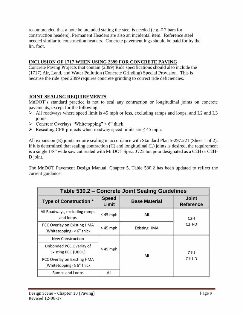
Design Scene – Chapter 10 (Paving) Revised 12-08-17
Page 9
recommended that a note be included stating the steel is needed (e.g. # 7 bars for
construction headers). Permanent Headers are also an incidental item. Reference steel
needed similar to construction headers. Concrete pavement lugs should be paid for by the
lin. foot.
INCLUSION OF 1717 WHEN USING 2399 FOR CONCRETE PAVING
Concrete Paving Projects that contain (2399) Ride specifications should also include the
(1717) Air, Land, and Water Pollution (Concrete Grinding) Special Provision. This is
because the ride spec 2399 requires concrete grinding to correct ride deficiencies.
JOINT SEALING REQUIREMENTS
MnDOT’s standard practice is not to seal any contraction or longitudinal joints on concrete
pavements, except for the following:
All roadways where speed limit is 45 mph or less, excluding ramps and loops, and L2 and L3
joints.
Concrete Overlays “Whitetopping” < 6” thick
Resealing CPR projects when roadway speed limits are ≤ 45 mph.
All expansion (E) joints require sealing in accordance with Standard Plan 5-297.221 (Sheet 1 of 2).
If it is determined that sealing contraction (C) and longitudinal (L) joints is desired, the requirement
is a single 1/8” wide saw cut sealed with MnDOT Spec. 3725 hot pour designated as a C2H or C2H-
D joint.
The MnDOT Pavement Design Manual, Chapter 5, Table 530.2 has been updated to reflect the
current guidance.
Table 530.2 – Concrete Joint Sealing Guidelines
Type of Construction * Speed
Limit Base Material
Joint
Reference
All Roadways, excluding ramps
and loops ≤ 45 mph All
C2H
C2H-D PCC Overlay on Existing HMA
(Whitetopping) < 6” thick > 45 mph Existing HMA
New Construction
> 45 mph
All C1U
C1U-D
Unbonded PCC Overlay of
Existing PCC (UBOL)
PCC Overlay on Existing HMA
(Whitetopping) ≥ 6” thick
Ramps and Loops All

Design Scene – Chapter 10 (Paving) Revised 12-08-17
Page 10
* For future concrete pavement rehabilitation (CPR) projects, follow the same recommended
practices as original construction. Contact the MnDOT Concrete Unit with questions.
Contact the Concrete Engineering Unit with any questions or concerns regarding the updated
guidance, or to discuss suitability of sealing joints on a specific project.
NON WEARING COURSE
Whenever non wearing course is referenced it should have a space between NON and WEARING
not a dash and not connected.
OVERLAY TRANSITION TAPERS
Currently, MnDOT does not have a policy or standard regarding the rate of transition tapers at the beginning and end of pavement overlays. As a result of this there is quite a variation in taper
rates used throughout the state, ranging from about 1:240 to 1:600. Experience in Minnesota
indicates that a transition taper of 1:400 results in an acceptable ride for high-speed roads. A
recent survey of other state DOT’s indicated that 1:400 is typical of taper rates used country-
wide.
In order to provide pavement overlay transitions that provide a smooth ride, yet are economical,
the rate of transition taper on pavement overlays should be determined from the following table.
DESIGN SPEED RATE OF TAPER 50 mph or greater
1:400
35 to 45 mph
1:300
30 mph or less
1:200
Prior to placement of an overlay, the in-place surface in each taper should be notched as shown
in the sketch below. Top of overlay Notch equal to the wearing course thickness (see table)
Top of existing roadway
QUALITY MANAGEMENT Please see chapter 7 for information regarding Quality Management and Quality Management
Special.

Design Scene – Chapter 10 (Paving) Revised 12-08-17
Page 11
RUMBLES IN CONCRETE
Sinusoidal rumbles should be used when placing rumble strips on concrete shoulders. These are
typically on the inside shoulders of a concrete roadway.
ROADWAY PROFILE FOR CONCRETE OVERLAYS
The Concrete Engineering Unit recommends establishing the roadway profile after placement and
compaction of the bond breaker layer/after completion of the bituminous milling. Contact the
Concrete Engineering Unit to discuss the options.
The Designer will need to select either MnDOT or Contractor Surveying language (2011) specific
to concrete overlays.
SUBRGADE PREPARATION
In the 2005 Spec Book it stated that…”Payment for subgrade preparation, as a separate item, will
be made only when the roadbed or other course being prepared was constructed under a previous
contract.”
The 2014 Materials Lab Supplemental Specifications for Construction book does not contain this
language. Therefore, If subgrade preparation is required on your project you either need to note it
as “Incidental” or use the pay item …2112 SUBGRADE PREPARTION.
The 2016 and 2018 Spec Book states, under 2105.5.E and 2106.5.E that subgrade preparation is
incidental unless there is a pay item for 2112 SUBGRADE PREPARATION.

Design Scene – Chapter 11 (Walls) Revised 08-03-15
Page 12
CHAPTER 11: WALLS
MODULAR BLOCK WALL (DRY CAST)
Rather than being pre-approved as systems, the components of Modular block walls (dry cast) are
pre-approved separately. The approved MBW components are located at:
http://www.dot.state.mn.us/products/walls/drycastwalls.html
The engineering design of MBWs is standardized and the standards are located at:
http://standardplans.dot.state.mn.us/StdPlan.aspx
There are several restrictions to MBWs located in the MnDOT Tech Memo No. 08-06-MRR-01,
“Use of Dry-Cast Segmental Masonry Retaining Wall Units”. Some of these restrictions are
summarized below:
1. No MBWs are allowed in locations where they will be directly supporting roadways or
bridge abutments as defined by a 0.5 H:1.0 V line extending up from the bottom back of the
reinforcement zone.
2. There will be no restrictions (beyond those listed above) for the location of walls less than or
equal to 4 ft in height (nominal height including terraces).
3. For MBWs only, the allowable placement locations for walls greater than 4 ft in height
(nominal dimension) are as follows:
Roadways with traffic volumes less than or equal to 5000 AADT - No restriction in
location.
Roadways with traffic volumes between 5000 and 20000 AADT - The face of block
of the walls must be located more than 20 ft beyond the outside shoulder edge or
gutter line.
Roadways with traffic volumes greater than or equal to 20000 AADT - The face of
block of the walls must be located greater than 30 ft beyond the outside shoulder
edge or gutter line.
4. For MBWs only, the maximum allowable nominal exposed wall height, including terraces,
will be 10 ft.
5. For MBWs only, all placement restrictions are measured from the front face of block.
The pay item for MBW’s is 2411.618 MODULAR BLOCK RETAINING WALL by SQ FT.
PREFABRICATED MODULAR BLOCK WALL (WET CAST)

Design Scene – Chapter 11 (Walls) Revised 08-03-15
Page 13
Prefabricated modular block walls (PMBWs) are systems which contain wet cast precast concrete
units, interlocking soil-filled reinforced concrete modules or bins or rock filled gabion baskets.
Modular block walls (MBWs) are systems which contain dry cast precast concrete units. Both wet
cast PMBWs and dry cast MBWs resist horizontal earth pressure by acting as gravity retaining
walls. Soil reinforcement can be added to wet cast PMBWs and dry cast MBWs to cause them to act
as hybrid systems. In these systems the reinforced soil mass and weight of the units are used to resist
the external horizontal earth pressure and other loads.
Dry cast MBWs have standards and technical memoranda that cover their design, while PMBWs are
complete prequalified engineered systems which consist of components such as block units, soil
reinforcement, connections, and geotextiles. A multidisciplinary team of MnDOT engineers
reviews each system before it is prequalified to bid on MnDOT projects. For PMBWs, MnDOT
divides the prequalification requirements into three phases:
Prefabricated Modular Block Wall (Wet Cast)
1- Phase I: Gravity PMBW (No soil reinforcement). The maximum exposed height of these
systems is 8 ft, where exposed height is defined as the distance from the finished ground line
at the top of the wall to the finished ground line at the base of the wall. Since this is a
gravity system with no redundancy, this wall type is not allowed to support a roadway. (See
Definition of Supporting Traffic: Gravity PMBWs below for the definition of supporting a
roadway)
2- Phase II: PMBW with soil reinforcement. The maximum exposed height of these systems is
10 ft. These are hybrid systems in which the reinforced soil mass and weight of the units are
used to resist the external horizontal earth pressure and other loads. Since soil reinforcement
is used, the units are typically shallower than in a gravity PMBW system. Properly
designed, these wall systems can be used to support an adjacent roadway.
3- Phase III: PMBW with soil reinforcement. The maximum exposed height of these systems is
18 ft. Like Phase II systems, these are hybrid systems in which the reinforced soil mass and
weight of the units are used to resist the external horizontal earth pressure and other loads.
Since soil reinforcement is used, this type of unit is typically shallower than in a gravity
PMBW system. The difference between Phase II and Phase III systems is that Phase III
systems require more scrutiny during the prequalification process. The application for
prequalification in a Phase III system requires a completed technical evaluation report from
the Highway Innovative Technology Evaluation Center (HITEC) or an independent review
by an equivalent MnDOT approved MSE wall system expert for compliance with AASHTO
requirements and a review by a multidisciplinary team of MnDOT engineers. Properly
designed, these wall systems can be used to support an adjacent roadway.
The MnDOT prequalified suppliers list (for all 3 phases) is located at:
http://www.dot.state.mn.us/products/walls/pmgbw.html

Design Scene – Chapter 11 (Walls) Revised 08-03-15
Page 14
Definition of Supporting Traffic: Gravity PMBWs
Gravity PMBWs are not allowed to support traffic. A vehicular roadway or parking lot shall not be
situated within a 1V:1H horizontal distance measured from the front face bottom corner of the
bottom block (see Figure 1). The horizontal distance shall be determined for each wall measured at
the highest portion of the wall. Since no vehicular live load is applied, a surcharge must be applied
to account for snow loads, future maintenance operations, or future regrading.
Figure 1 Definition of Supporting Traffic for a Gravity PMBW
Definition of Supporting Traffic: PMBWs with Soil Reinforcement
PMBWs with soil reinforcement are considered to support traffic if a vehicular roadway or parking
lot is located within a horizontal distance measured from the front face of the bottom block equal to
(Du + L + 0.5 RH), where:
Du = Depth of the Unit (assume 3’)
L = Length of Reinforcement (Minimum of 0.7 x RH or 8’)
RH = Design Height of PMBW with Soil Reinforcement
The horizontal distance shall be determined for each wall measured at the highest portion of the
wall. Due to grading, design, and visual quality issues between the edge of pavement or roadway
and the back of a wall, traffic may not be placed within a horizontal distance of 11’ (assumes 3’
block depth + 8’ behind back of wall) from the front face of the wall, regardless of height (See
Figure 2).

Design Scene – Chapter 11 (Walls) Revised 08-03-15
Page 15
Figure 2 Minimum Traffic Distance for a PMBW with Soil Reinforcement
PMBW Guidelines for Roadway Designers
The following are some of the key guidelines for roadway designers when using PMBWs.
1- Work with the geotechnical engineer to obtain a Foundation and Analysis Design
Recommendation (FADR) before the wall selection process. At a minimum the FADR
should consider the following:
a. Global stability should be addressed in the report.
b. Strength parameters, including the friction angles and cohesion (if applicable) of the
in-situ soils, should be listed.
c. Static and high groundwater levels should be listed.
d. Predicted total and differential settlement should be listed. Differential settlement
shall be less than 1/200 along the length of the wall and normal to the wall alignment.
2- PMBW’s (gravity or reinforced) should only be used on projects where the roadway
designer has verified that the ground water table is below the elevation of the proposed
leveling pad AND all drainage systems installed behind the wall can be day-lighted to a
ditch or subsurface drainage system. If these conditions cannot be met or verified by the
roadway designer, this type of wall system should not be specified. Design or installation of

Design Scene – Chapter 11 (Walls) Revised 08-03-15
Page 16
prefabricated modular block walls in “bath tub” conditions or in un-drained soils is
prohibited.
3- No drainage systems other than what is required for the wall and highway drainage shall be
placed within the reinforced soil zone. The wall design shall include the necessary details or
design modifications to accommodate the drainage system. The placement of the drainage
system shall occur only during construction backfilling of the wall.
4- PMBWs with soil reinforcement shall include a drainage system on top of the concrete
leveling pad at the interface of the reinforced and the retained soil (see Figure 3).
5- Only PMBW systems listed on the MnDOT prequalified supplier list at the letting date will
be allowed.
6- Check with the Bridge Office if there are structures or large signs supported by the wall.
7- State the prequalification phase(s) (I,II or III) required for the project.
8- Corners are limited to 90 degrees inside and outside corners. Minimum radius for PMBW is
15’.
9- No drilling or driving of posts (sign, guardrail, etc.) or other roadside hardware in the
reinforced zone shall occur after placement of the reinforced soil. If such roadside hardware
is required, the design and plans shall include details such as sleeves to accommodate it. If a
railing or fence post is placed on the top of the blocks, the designer needs to have a note on
the plan requiring the wall supplier to be prequalified for the railing placement.
10- Depending on PMBW wall height variations, sometimes it may be desirable to use both
gravity and reinforced wall types on the same wall. In these situations, gravity walls shall be
used to a maximum wall height of 8' exposed and reinforced walls used to a maximum
height of 18' exposed. The same pay item, 2411.618 PREFABRICATED MODULAR
BLOCK WALL, by SQ FT. shall be used for both gravity and reinforced PMBWs.
11- Decide on architectural details, including surface pattern and texture, joint layout and details,
and surface finish and color.

Design Scene – Chapter 11 (Walls) Revised 08-03-15
Page 17
Figure 3: PMBW with Soil Reinforcement Material Definitions/ Typical Cross Section

Design Scene – Chapter 11 (Walls) Revised 08-03-15
Page 18
Figure 4: Gravity PMBW Material Definitions/ Typical Cross Sections
12- Gravity PMBWs can have either a 2’ concrete leveling pad or a composite leveling pad
consisting of 6” min. of concrete and coarse filter aggregate. In either case, the bottom of the
leveling pad must be at least 4’ below the finished ground line at the bottom of the wall.
Gravity PMBWs with a concrete-only leveling pad shall include a drainage system on top of
the concrete leveling pad (see Figure 5). The drainage system shall consist of perforated pipe
per MnDOT 3245 wrapped with a type 1 geotextile per MnDOT 3733. The pipe shall be
placed such that water drains freely from the pipe, typically at a 1% grade with 3 foot
minimum radius bends. Provide outlets as required due to expected flow rate with a
maximum spacing of 150 feet. Outlet the drainage system through the slope in front of the
wall with a concrete headwall per MnDOT Standard Plate 3131 or into a drainage structure
(see Figure 3). The designer shall take into account the location of wall drainage systems in
the layout and step locations of wall leveling pads and ensure the wall drainage system is
compatible with the leveling pad step locations. The shop drawings for each wall shall
denote the location of the drainage system components, including the station of each outlet

Design Scene – Chapter 11 (Walls) Revised 08-03-15
Page 19
penetration through the wall and whether the flow is outletted through the slope in front of
the wall or into a drainage structure.
Figure 5 – Full depth concrete leveling pad detail
The composite leveling pad shall consist of a 6” min. thickness concrete slab over a 6” min.
thickness of compacted drainable coarse filter aggregate per MnDOT Spec 3149.2H. The
coarse filter aggregate shall be completely wrapped with a Type 1geotextile fabric per
MnDOT Spec 3733 (see Figure 6). The bottom of the leveling pad must extend at least 4’
below grade. Drains shall be required at the bottom of the coarse filter aggregate and
directly above the concrete.
Figure 6 - Composite leveling pad detail (gravity walls only)
The pay item for PMBW’s is 2411.618 PREFABRICATED MODULAR BLOCK WALL
by SQ FT
RETAINING WALLS

Design Scene – Chapter 11 (Walls) Revised 08-03-15
Page 20
The following is in the process of being prepared for possible inclusion into the RDM. The
information was deemed important so that it is incorporated in the Design Scene for designers
information.
Standard plans for cast-in-place retaining walls are included in the Standards Plans Manual or at the
following website… http://standardplans.dot.state.mn.us/StdPlan.aspx
on sheets 5-297.620 through 5-297.639 The plans include standard designs for wall heights up to 30
feet with three loading conditions and two types of foundations: spread or pile. The loading
conditions are:
1. Level Backfill
2. Level backfill with 2 ft. live load surcharge (roadway adjacent to top of wall)
3. 1:2 sloped backfill
These standard designs are in accordance with AASHTO LRFD Specifications using the design
parameters shown on Standard Plan sheet 5-297.639. A Foundations Report is prepared for each
specified wall project and contains a footing recommendation.
Alternate wall designs are non-standard designs consisting of either proprietary or special wall
designs.
Proprietary designed walls are provided by vendors from pre-qualified product lists that meet
project specifications. All mechanically stabilized earth (MSE) walls fall into this category
including prefabricated large wet-cast concrete modular block walls.
Mechanically stabilized earthen panel walls and prefabricated large wet-cast concrete modular block
should only be used on projects where the roadway designer has verified that the ground water table
is below the elevation of the proposed leveling pad AND that all drainage systems installed behind
the wall can be day lighted to a ditch or subsurface drainage system. If these conditions cannot be
met or verified by the roadway designer this type of wall system should not be specified (An
exception to this requirement may be granted for gabion basket walls by the Foundations Unit).
Design or installation of mechanically stabilized earth walls in “bath tub” conditions or in undrained
soils is prohibited.
Specially designed walls do not fall into the standard or proprietary wall categories. These include
cast-in-place cantilever walls taller than those shown on the standard plan sheets, steel sheet pile,
soil nail, soldier pile and anchored walls.
Design Responsibility The roadway designer has the responsibility to lead the plan development effort by coordinating the
wall type selection process. The designer shall collect from the offices listed below the aesthetic
requirements and the technical recommendations regarding the structural and foundation aspects of
the wall. All various wall types described later in this section should be considered in the selection
process so that the most cost-effective and appropriate wall is constructed.

Design Scene – Chapter 11 (Walls) Revised 08-03-15
Page 21
The road designer also has the responsibility to develop the plan, profile, cross sections and staging
of the retaining wall and to prepare the construction plans.
The Structural Wall Committee (SWC) is responsible for establishing guidelines for submittals and
for submittal review of new wall types used in MnDOT projects. The approved wall systems are
listed on MnDOT Approved Products website.
Standard cast-in-place wall designs which cover a wide range of situations are available in the the
Standard Plans Manual. These standard designs were developed by the Bridge Office and may be
used without a structural review. Alternate and non-standard designs, which include proprietary
walls and walls not covered by available standards, require a special design by the Bridge Office or
a consultant. It is the responsibility of the road designer to contact the Bridge Office to determine
whether the non-standard wall design is completed by the Bridge Office or by others and to
determine the timing and work effort involved.
The Foundations Unit is responsible for all geotechnical aspects of retaining walls and for preparing
a foundation report for all wall types suggested by the road designer. The Foundations Unit should
coordinate the subsurface investigation, perform laboratory analysis/testing, conduct a global and
compound stability analysis (if required) and provide recommendations for the in-situ soil design
parameters and foundation type. This responsibility is deferred to the District Soils Engineer for
walls less than 5 feet high.
The Office of Environmental Stewardship, Environmental Planning and Design Unit and the Bridge
Office Architecture Specialist, should be contacted regarding aesthetic and/or rustication treatments
for retaining walls.
Preparation of Bid Documents and Plans
Wall plans fall into three categories; standard design, special design, and proprietary
design. Currently, cast-in-place cantilever walls and dry cast concrete modular block walls have
standard plan sheets. Preparation of plans and bid documents for all walls excluding proprietary
walls should include complete details necessary for the construction of the walls using the standard
plan sheets and specifications in combination with project specific information shown on additional
sheets.
Special design walls include cast-in–place cantilever walls taller than those shown on the standard
sheets, steel sheet pile, soil nail, soldier pile and anchored walls. Preparation of plans for these
walls should include complete details necessary for the construction of the wall using project
specific details and any standards or special requirements that may apply.
Plans for proprietary design walls should include pertinent information necessary for location and
alignment including cross sections, plans, and profiles. Locations of drainage systems, utilities or
other features impacting the design or construction should also be shown. The balance of the details
necessary for construction shall be provided by the wall vendor via the contractor as described in the
Special Provisions.
Proprietary Designed walls
Design Scene – Chapter 11 (Walls) Revised 08-03-15
Page 22
Per MnDOT specifications, all proprietary designed walls will be selected from the MnDOT Pre-
qualified supplier lists, so it is not necessary to get a public interest finding for walls meeting the
specifications.
All proprietary wall designs shall contain the following geometric and project specific information:
1. List of acceptable wall types and/or systems for each wall on the project.
2. Drainage
Proprietary designed walls shall include a drainage system consisting of perforated pipe per
MnDOT 3245 wrapped with a type 1 geotextile per MnDOT 3733. The pipe shall be placed
such that water drains freely from the pipe, typically a 1% grade and 3 foot minimum radius
bends. Provide outlets as required due to expected flow rate with a maximum spacing of 150
feet. Outlet the drainage system through the slope in front of the wall with a concrete
headwall per MnDOT Standard Plate 3131 or into a drainage structure. The designer shall
take into account the location of wall drainage systems in the layout and step locations of
wall leveling pads and to ensure the wall drainage system is compatible with the leveling pad
step locations. The designer shall denote the location of the drainage system components,
including the station of each outlet penetration through the wall and whether the flow is
outletted through the slope in front of the wall or into a drainage structure.
3. Geometrics
a. Beginning and end of wall stations.
b. Top of wall profile.
c. Original and proposed ground line profiles in front of and behind the retaining wall. Profiles
shall show all existing and proposed infrastructure (e.g., utilities and other existing or
proposed structures) in the profile section.
d. Cross sections at relevant wall locations, usually at no more than 50 feet intervals. Cross
sections shall show temporary and permanent Right-Of-Way (ROW) easement limits and
existing utilities.
e. Plan view(s) of wall alignment showing ROW limits, existing and proposed utilities, etc.
f. Wall alignment geometric data shall be shown and tabulated (similar to roadway alignment
data).
g. Details of foundation, leveling pad, aesthetics, or other detailed wall requirements.
h. Details of wall appurtenances such as traffic barriers, moment slabs, coping, fencing,
drainage, or other obstructions including but not limited to the location and configurations of
signs and lighting including conduit locations and right-of-way limits.
i. Construction staging requirements, if applicable, including sequence of traffic control,
access, temporary construction, temporary fencing, temporary or permanent barrier, and
temporary and permanent drainage.
j. Elevation of highest permissible level for foundation construction.
k. Location, depth and extent of any unsuitable material to be removed and replaced. Details of
any required ground improvement.
l. Quantities table showing estimated wall area and quantity of appurtenances and traffic
barriers, together with notes identifying the assumptions made in estimating.
m. At abutments, elevations of bearing pads, location of bridge seat, skew angle and all
horizontal and vertical survey control data including clearance and details of abutments.

Design Scene – Chapter 11 (Walls) Revised 08-03-15
Page 23
n. At stream locations, extreme high water, normal water levels and estimated scour depth.
o. Grading material requirements adjacent to the wall, including details of any needed
perforated pipe drainage or any other drainage requirements.
4. Geotechnical information
A copy of the subsurface investigation report and specific design values for the following
parameters (where required)
a. Plan view of sampling, testing and boring locations across project site.
b. Subsurface profile across project site.
c. Boring logs.
d. All laboratory test data and results.
e. Engineering properties of the foundation soil, reinforced soil, and retained soil as appropriate
to ensure the proper long-term performance of the MSE wall structure.
f. Required soil modification.
g. Global and compound stability analysis.
h. Allowable and ultimate bearing pressure beneath the wall footing and the reinforced earth
mass.
i. Settlement analysis for the foundation soil beneath the wall and the reinforced earth mass.
j. Groundwater elevations, any free water conditions, anticipated high water conditions and
any required drainage schemes.
k. Recommendations concerning items that may be appropriate to ensure the proper long-term
performance of the wall structure.
l. Shear strength (drained and undrained for fine grained soils) of foundation soils.
m. Required shear strength and unit weight ranges of select backfill.
n. Shear strength of random fill or in-situ soil behind wall
5. General Structural and Geotechnical Design Requirements
The following are general design requirements for retaining walls that will be shown on the
drawings or addressed in the contract documents. Specific design requirements for each of the
wall types are discussed in the following sections
o. Design Life of the structure (example: permanent mechanically stabilized earth walls are
designed, for minimum corrosion service life of 100 years)
p. Driving force and resistance for overturning, sliding and stability of temporary construction
slopes. Analysis for global and compound stability is performed by Foundation Unit.
q. Ultimate and nominal foundation bearing pressure, minimum wall footing embedment depth
and maximum tolerable total and differential settlements.
r. Internal design requirements for mechanically stabilized earth wall products.
s. Magnitude, location and direction of external loads due to bridge, overhead signs and lights,
traffic surcharge and rapid ground water draw down or displacements and any other external
loads.
t. Limits and requirements for drainage features beneath, behind, or through retaining
structure.
v. Backfill requirements for both within and behind retaining structure.
w. Requirements for special facing panels, module finishes, colors, and/or protective coatings.
Governing sections of construction specifications.

Design Scene - Chapter 12 (Drainage) Revised 12-08-17
Page 1
CHAPTER 12: DRAINAGE
CHINOOK WINDS AND WINTER SNOWS
A combination which frequently results in hazardous winter conditions on shaded portions of roadways under bridges. Icing conditions are a danger in themselves, and they present further
hazards during corrective maintenance operations. Paradoxically, they melt away maintenance
funds. Potentially hazardous conditions and rising maintenance costs often can be prevented by
thoughtful design. Hydraulics Engineers, request that designers place catch basins in such a
manner so that runoff in gutters can be intercepted before it can flow under bridges to freeze in
those shaded areas. This is a relatively simple design concept which, if employed wherever
feasible, will not only reduce recurring maintenance cost, but may also prevent bodily harm and
property damage. All surface design features should be carefully evaluated to minimize or
prevent, where possible, the flow of water across pavement surfaces. This is especially important
in the case of water from winter thaws. For example, snow and ice accumulations on raised
islands thawing, and then freezing on the road surface, might be prevented by use of a drained,
depressed island.
CLASSES FOR REINFORCED CONCRETE ARCH PIPE
Class IIA is the only class available for pipe arches with a nominal span less than 73 inches. Class IIA is designed for 0’ to 8’ of cover. For pipe arch sizes 73 in. or greater, Class
IIA, IIIA and IVA are available. Refer to Standard Plate No. 3014 for further information.
CULVERT APRONS IN THE CLEAR ZONE
Several designers have shown confusion with when to use safety aprons and or grates. They should refer to Chapter 8 of the Road Design Manual for this information.
It is recommended that ALL entrance culverts have safety aprons and/or grates within the clear
zone.
CULVERT WORK Whenever you revise a portion of a culvert, such as a lining or a salvage/install apron. You need
to make sure that the aprons are up to current standards. If a safety apron and/or grate is needed
and the existing apron does not meet this then the designer must replace the apron to bring it up to
current standards.
DRAINAGE FLOW ARROWS
Plans should contain drainage flow arrows on the plan sheets indicating the direction of flow for culverts, bridges, ditches, ditch breaks, etc..

Design Scene - Chapter 12 (Drainage) Revised 12-08-17
Page 2
DRAINAGE STRUCTURES ON ALTERNATE BID PLANS When doing alternate bid plans the designer needs to pay attention to the drainage structures. How
they are handled may be different in a bituminous plan versus a concrete plan. There have been
some issues with the inlet pads not being accounted for on the alternate projects.
FINE FILTER AGGREGATE FOR SUBSURFACE DRAINS
Under the Spec 2502 in the 2016 and 2018 Spec Book it is not clear how fine filter aggregate is
being paid for. Therefore, whenever using 2502 pipe drain items you will need to note somewhere
in the plan that the fine filter aggregate is incidental.
GRATES
The type of grate used with a catch basin does affect the amount of runoff intercepted along a curb and gutter. The location of the catch basin, whether on a slope or at a low point, also should
be considered when choosing the type of grate to be used. The advantages and disadvantages of
some of MnDOT grates are as follows:
Grate Advantages Disadvantages
Standard Plate 4154
(vane type)
(Grate Casting 816)
1.
2.
Tends not to plug with
debris.
Intercept large flow
1. Has less capacity at low
Points than parallel grate
Std. Plate 4153.
3.
Depths on steep slopes with no flow across grate.
Bicycle safe when installed
placed in correct position.
Standard Plate 4152
1.
Bicycle safe
1. Tends to plug with debris
(vane type) (Grate Casting 814)
2.
Accommodates foot traffic Debris.
2. Water will tend to skip across grate with large with
large flow depths on Steep
slopes.
The above information indicates that the vane type grate (Standard Plate 4154-Grate Casting
816) should be used on grades. The parallel type grate (Standard Plate 4153 - Grate Casting
815) is recommended at low point except where bicycle traffic is expected. If the low point
structures may have bicycle traffic, the vane grate (816) is recommended.
See Design Scene Chapter 3 – “ADA SAFETY GRATES, CURB BOXES, and HELPER
STRUCTURES” for more information.
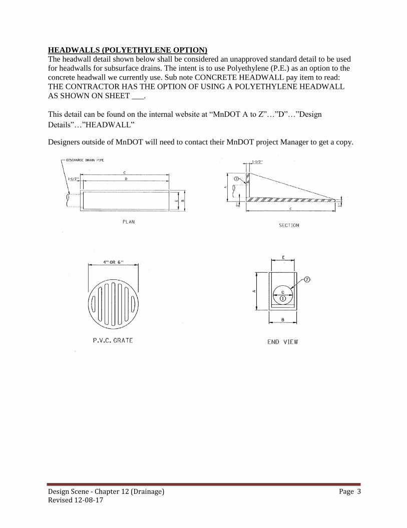
Design Scene - Chapter 12 (Drainage) Revised 12-08-17
Page 3
HEADWALLS (POLYETHYLENE OPTION)
The headwall detail shown below shall be considered an unapproved standard detail to be used for headwalls for subsurface drains. The intent is to use Polyethylene (P.E.) as an option to the
concrete headwall we currently use. Sub note CONCRETE HEADWALL pay item to read:
THE CONTRACTOR HAS THE OPTION OF USING A POLYETHYLENE HEADWALL
AS SHOWN ON SHEET ___.
This detail can be found on the internal website at “MnDOT A to Z”…”D”…”Design
Details”…”HEADWALL”
Designers outside of MnDOT will need to contact their MnDOT project Manager to get a copy.

Design Scene - Chapter 12 (Drainage) Revised 12-08-17
Page 4
INPLACE DRAINAGE STRUCTURES
On projects where inplace manholes or catch basins are likely to be either adjusted or reconstructed, the following additional information is necessary from survey crews.
Design or type of structure
Cone Type A, B or C.
Height of adjusting rings – if no rings, indicate this
Height of casting
This information is also necessary when the design requires connecting new drainage structures
to inplace structures. Please inform you District Surveys Engineer of these requirements.
Also, during review of supplemental agreements, we noticed several agreements had to be
processed due to the incorrect size of existing storm sewer pipes in the plan. A more careful
check, especially those pipes that require extensions, is in order.

Design Scene - Chapter 12 (Drainage) Revised 12-08-17
Page 5
PARALLEL PIPES AND APRONS IN THE MEDIAN Parallel pipes located in the median require safety aprons, must be grated, and the slope modified
to a 1:10. The only apron design that must be used is Apron and Grate Design 3128. Standard
Plate 3148 CANNOT be used for this application. If concrete pipe is used standard plate 3128
covers the connection to the concrete pipe. The plan must also include a design detail for the 1:10
apron.
These details can be found on the internal website at “MnDOT A to Z”…”D”…”Design
Details”…”SAFEAPRN1_10B” or “SAFEAPRN1_10SM”
Designers outside of MnDOT will need to contact their MnDOT project Manager to get a copy.
PIPE BEDDING The 2016 and 2018 Spec book does not reference the various bedding classes (e.g. B, C) but just
refers to it as bedding. Therefore, we can no longer call out the pipe bedding class in the plans, it
should just be referred to as “bedding”. The pipe bedding details could reference Spec 2451 for
bedding requirements.
PIPE GAUGES
Standard Plate 3041. This plate allows a lighter gauge metal pipe above 36 in. diameter than Standard Plate 3040. Therefore, it is better not to show any gauge within a plan
unless a heavier than standard gauge is required (lighter than standard are never used). When a
heavier gauge is called for, it should be sub noted as below:
2501.503 42” CAS PIPE CULVERT 10 GAUGE (1)
(1) A 10 gauge is required per Standard Plate 3040 or a 12 gauge per Standard Plate 3041.
NOTE: (1) above is assuming that the gauge requirements are based on fill conditions only. If a
heavier gauge is desired for velocity - durability reasons, note (1) above should state that
regardless of which plate is used, a 10 gauge pipe is required.

Design Scene - Chapter 12 (Drainage) Revised 12-08-17
Page 6
PIPE LINING There has been some confusion regarding pipe lining, hopefully this will clear it up...
Lining pipes must state the size of the pipe being lined….
2503.603 LINING SEWER PIPE__” by the LIN FT…grout is incidental unless otherwise
noted.
2507.503 LINING CULVERT PIPE (__”) by the LIN FT, when using this pay item they also
need to include either…
2519.507 CLSM LOW DENSITY by the CU YD or
2519.507 CLSM HIGH DENSITY by the CU YD or
If using cured in place pipe (CIPP) then pay for it as 2507.603 LINING CULVERT PIPE
(__”) SPECIAL by the LIN FT. Add a note stating it is Cured in Place Pipe (CIPP)
because sometimes it is special but not because it is CIPP. A special provision is required
for this and is being updated on a regular basis. Please contact the State Hydraulics
Engineer for this write-up.
PLASTIC PIPE OPTION FOR STORM SEWER AND CULVERTS
There has been some confusion with this article given the latest Technical Memorandum 17-5-B-
02 issued 4-25-2017.
How plastic pipe options has not changed as a result of this Technical Memorandum. Pay for
them as the existing/previous article states. The major change for this is that when listing options
the designer CAN now also include PP (polypropylene pipe).
When giving plastic pipe as an option the plan should include the detail from
Attachment D if using flexible pipe for storm sewer,
Attachment E (First detail) if giving flexible pipe as an option for centerline culvert.
Attachment E Treatment types if giving flexible pipe where treatments are needed.
The designer should use these details not ones they created.
Mn/DOT has agreed to include acceptable pipe materials within its construction plans. It has
been determined that plastic pipe should be used more uniformly statewide for storm sewer and
culverts if the plastic pipe design criteria are met. This is being provided in response to industry
concern that plastic pipe, although an approved material was not being included as a bid alternate.
Designers may continue to specify a particular product to be used when professional engineering
judgment determines that circumstances warrant. When this is the case the designer should keep
written documentation in the project file on why the option was not used.
Plastic pipe should be used in accordance with Technical memorandum No. 17-05-B-02.
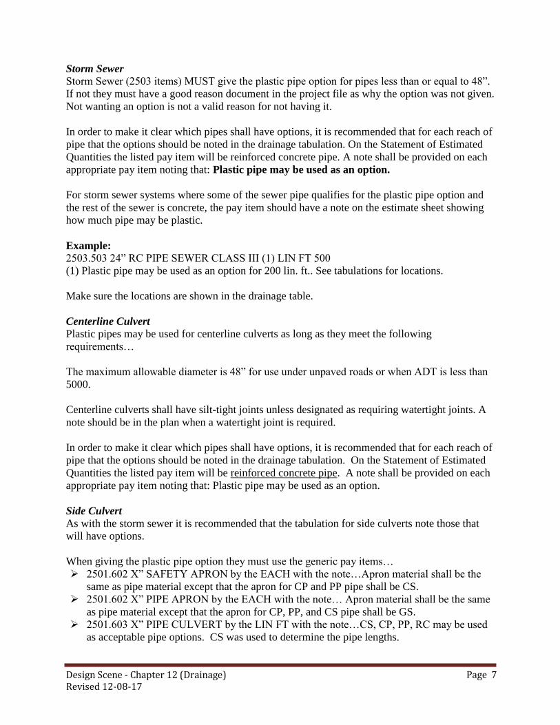
Design Scene - Chapter 12 (Drainage) Revised 12-08-17
Page 7
Storm Sewer
Storm Sewer (2503 items) MUST give the plastic pipe option for pipes less than or equal to 48”.
If not they must have a good reason document in the project file as why the option was not given.
Not wanting an option is not a valid reason for not having it.
In order to make it clear which pipes shall have options, it is recommended that for each reach of
pipe that the options should be noted in the drainage tabulation. On the Statement of Estimated
Quantities the listed pay item will be reinforced concrete pipe. A note shall be provided on each
appropriate pay item noting that: Plastic pipe may be used as an option.
For storm sewer systems where some of the sewer pipe qualifies for the plastic pipe option and
the rest of the sewer is concrete, the pay item should have a note on the estimate sheet showing
how much pipe may be plastic.
Example:
2503.503 24” RC PIPE SEWER CLASS III (1) LIN FT 500
(1) Plastic pipe may be used as an option for 200 lin. ft.. See tabulations for locations.
Make sure the locations are shown in the drainage table.
Centerline Culvert
Plastic pipes may be used for centerline culverts as long as they meet the following
requirements…
The maximum allowable diameter is 48” for use under unpaved roads or when ADT is less than
5000.
Centerline culverts shall have silt-tight joints unless designated as requiring watertight joints. A
note should be in the plan when a watertight joint is required.
In order to make it clear which pipes shall have options, it is recommended that for each reach of
pipe that the options should be noted in the drainage tabulation. On the Statement of Estimated
Quantities the listed pay item will be reinforced concrete pipe. A note shall be provided on each
appropriate pay item noting that: Plastic pipe may be used as an option.
Side Culvert
As with the storm sewer it is recommended that the tabulation for side culverts note those that
will have options.
When giving the plastic pipe option they must use the generic pay items…
2501.602 X” SAFETY APRON by the EACH with the note…Apron material shall be the
same as pipe material except that the apron for CP and PP pipe shall be CS.
2501.602 X” PIPE APRON by the EACH with the note… Apron material shall be the same
as pipe material except that the apron for CP, PP, and CS pipe shall be GS.
2501.603 X” PIPE CULVERT by the LIN FT with the note…CS, CP, PP, RC may be used
as acceptable pipe options. CS was used to determine the pipe lengths.

Design Scene - Chapter 12 (Drainage) Revised 12-08-17
Page 8
Other
Plastic pipe is dependent on soil interaction for support. Adequate compaction must be attainable
for the pipe to perform satisfactorily. Areas of high groundwater or unusual soil conditions may
not be suitable if compaction is not certain. Follow the design criteria in the Technical
Memorandum which provide guidance on acceptable pipe sizes, cover requirements, allowable
ADT for centerline culvert, and other considerations. Designers need to apply engineering
judgment in such situations and limit the types of pipe materials allowed if site conditions may
result in an unsuccessful installation.
STANDARD PLATE 3022
This standard plate is used for safety aprons up to and including 36 inches. Standard Plate 3022 shows two design options (No. 1 & No. 2). When using this plate the designer should indicate on the drainage tabulation which option was used to determine the length of pipes. STANDARD PLATE 4134 Standard plate 4134, Curb Box Casting for Catch Basin (for Design B Curbs), was created
specifically for use with 4” B curb. Some problems have occurred with this curb box. Input from
the districts and the Bridge Hydraulics Section indicate that breakage has been caused by
installation problems. Curb boxes are considered effective only at low-points and should normally
not be used at structure locations on-grade. Proper field installation of curb boxes is important, but
designers should avoid their use except at low-points. This is especially important when designing
for 4” curb and gutter.
This box does not fit on our standard structures; therefore, when using this you need to place it on
a structure with a 30” opening such as a Drainage Structure Design N or Drainage Structure
Design 4020 or SD with a modified cover with larger hole.
.
.

Design Scene – Chapter 13 (Turf Establishment & Erosion Control) Revised (12-08-17)
Page 1
CHAPTER 13: TURF ESTABLISHMENT and EROSION CONTROL
CULVERT END ENERGY STABILIZATION
All culvert outfall ends require some form of energy stabilization, and is critically important on
safety aprons. Not every culvert end needs riprap, and in some circumstances, the flared end is
sufficient. See Standard Plans detail for culvert end stabilization quantities.
EROSION CONTROL BLANKET PRODUCTS (RECP)
Spec 2016 and 2018 … Pay items for CATEGORY 3 and CATEGORY 4 EROSION CONTROL
BLANKETS have multiple options that fall under the same pay item. If these options are not
specified, the default will typically be a blanket with plastic netting and straw fill because this is
often the lowest-cost blanket. While this may meet the needs of the project, be aware that this is a
less expensive product and there may be disputes if a change is asked for in the field. Clarify the
expected options to avoid confusion.
Netting… use the suffix “P” (for plastic netting) or “N” (for natural netting) as part of the pay
item description. Plastic netting is more common and often less expensive. However, natural
netting may be desired or even required due to concerns about animal entanglement, permit
requirements, appearance, difficulty of mowing, or other reasons.
Fill Material…is not included in part of the pay item description however it should be identified
in a note either in the SEQ or Tabulation.
For example..
“Category 3N (Wood Fiber)” identifies category 3 blanket with natural netting and wood
fiber
“Category 3P (Straw)” means the blanket will have plastic netting and straw fill material.
Wood fiber may be preferred in concentrated flow conditions such as ditch grades. Wood
fiber may last longer than straw.
The same options exist for Category 4 blankets, with the exception that the “Straw” filler for
Category 4 blankets is actually a straw/coconut blend. Do not rely solely on the plan sheets or the special provisions to clarify these options—
include them on the SEQ and/or Tabulations to reduce confusion and disputes on projects.
For example it is recommended that it be shown in the plan as follows….
If you do not have a preference for the fill material then do not use note one and do not break it out
in the tab (e.g. straw or wood fiber…just one column instead of two).
TABSHT
NOITEM NO DESCRIPTION NOTES UNITS
TOTAL
EST
QUANT
E 15 2575.504 EROSION CONTROL BLANKETS CATETORY 3N ① SQ YD 400
E 15 2575.504 EROSION CONTROL BLANKETS CATETORY 3P ① SQ YD 300
① WOOD FIBER IS REQUIRED FOR SPECIFIC AREAS ON THE PLAN, SEE TAB FOR LOCATIONS.
STATEMENT OF ESTIMATED QUANTITIES

Design Scene – Chapter 13 (Turf Establishment & Erosion Control) Revised (12-08-17)
Page 2
EROSION CONTROL SUPERVISOR
Erosion Control Supervisor will be required on all MNDOT Projects when there are vegetation or
pervious surface disturbing activities or working in public waters. Method of payment for the
erosion control supervisor is highlighted in the following table:
EROSION CONTROL SUPERVISOR
Description of Project Method of Payment
Less than 1 acre land disturbance with minimal to moderate risk of
impacts to resource waters. Duration of project 1 construction season.
(examples include; projects more than 100 feet from public waters,
culvert extensions, ADA, Signalization )
Incidental
One (1) acre or more of land disturbance with minimal to moderate
risk of impacts to resource waters. Duration of project 1 construction
season.
(Examples include; landscape projects, mill and overlay projects, turn
lanes, etc.)
Incidental
Less than 1 acre land disturbance with high risk of Impacts to resource
waters. Duration of project 1 to two construction seasons (Examples
include culvert replacements in streams, work on river/stream banks
and shorelines, bridge work over public waters, etc.)
Lump Sum
One (1) acre or more of land disturbance with high risk of impacts to
resource waters. Duration of project 1 or more construction seasons.
(Examples include; culvert replacements in streams, work on
river/stream banks and shorelines, grading/surfacing, etc.)
Lump Sum
One (1) acre or more of land disturbance with low risk of impact to
resource waters. Duration of project 1 to two construction seasons.
(Examples include grading/surfacing in rural areas and no public water
crossings)
Incidental/lump sum
(Designers Discretion)
When the erosion control supervisor is incidental include in the construction notes the following:
Erosion control supervisor is required for this project and will be incidental. Also include a
standard boiler plate special provision (Special Provision (2573) Erosion Control Supervisor).
E
RT
LT
RT
LT
17+00 to 20+00 200
17+00 to 20+00 100
13+00 to 17+00 150
EROSION CONTROL
BLANKETS
CATEGORY 3N
(STRAW)
13+00 to 17+00 250
EROSION CONTROL BLANKETS
TABULATION TOTAL
EROSION CONTROL
BLANKETS
CATEGORY 3N
(WOOD FIBER)
EROSION CONTROL
BLANKETS
CATEGORY 3P
(STRAW)
EROSION CONTROL
BLANKETS
CATEGORY 3P
(WOOD FIBER)
STA TO STA LOC
SQ YD SQ YD SQ YD SQ YD
400 300

Design Scene – Chapter 13 (Turf Establishment & Erosion Control) Revised (12-08-17)
Page 3
MULCH MATERIAL TYPE 4 As stated in the 2016 Spec Book, Type 4 Mulch Material is paid for by the acre, but in the 2018
Spec Book it is paid by the square yard. This includes MULCH MATERIAL TYPE 1or 3 (you must
designate Type 3 by a footnote in SEQ if using seed mixes 3x-xxx in the plan).
NATIVE MIXES
MnDOT will be increasing the use of native species on the roadsides. The 2X-XXX series
(composed of primarily non-native species) will continue to be utilized on regularly mowed areas
such as in-slopes (e.g. top 8-15ft) and residential and commercial areas. The 3X-XXX series
(composed primarily of native species) were designed in part to protect and enhance natural
resources, promote biodiversity, display native vegetation, introduce travelers to the regional
physical or biological character of the native landscape, and enhance visual quality by using
vegetation to frame or screen views to and from the roadway corridor. The new District Vegetation
Establishment Memo’s will have recommended mixes for riparian areas, roadside ditches, and
backslopes. They may differ from district to district and within each district due to adjacent habitat,
ecological characteristics, or desired visual quality and aesthetics. Project designers will be given
options based on the contextual setting of the road segment. It will become more common to have
projects with both native mixes and non-native mixes. An example would be to have native mixes
(3X-XXX series) on the backslope and ditch bottom, while the inslope and/or median may be a non-
native mix (2X-XXX series).
The use of native seed mixes are often required to be utilized for mitigation due to impacts regulated
by other agencies, such as when a project requires a DNR Public Waters Permits. In fact, this is a
standard condition of the DNR General Permit to MnDOT for repair or bridges and culverts
(GP2004-0001). The DNR may also require that native vegetation be utilized when projects run
through or adjacent to DNR managed lands such as Wildlife Management Areas, Scientific &
Natural Areas, Public Access, State Parks, State Forests, etc. Native vegetation suitable to the local
habitat is also recommended when projects run through or adjacent to areas that include rare species,
in areas identified as a Site of Biodiversity Significance, or in an Area of Environmental Sensitivity
(AES). The DNR is not alone in these requirements. Use of native vegetation can come up by
request from adjacent landowners or from other regulatory compliance measures as well.
SEDIMENT CONTROL STANDARD PLAN SHEETS
Temporary Sediment control standard plan sheets are updated to reflect the 2016 Specifications for
Construction, division II 2573 specifications. Refer to the Standard Plans for Drainage and Erosion
Control. Only use the sheets that pertain to the project and associated pay items.
SITE MANAGEMENT PLAN (SMP)
Site management plan are areas designed to help the project engineer visualize and analyze the
actual work the contractor will perform when working in areas of environmental sensitivity and
other critical areas. Types of work include all center line culverts, all bridge types, all in-water or
over-water works, all dewatering, and engineered slopes (e.g. RSS walls). Tabulate and show these
SMP areas in the plan.
Design Scene – Chapter 13 (Turf Establishment & Erosion Control) Revised (12-08-17)
Page 4
STRAW MULCH MATERIALS
Mulch material Type 3 (certified grain straw) is recommended to limit the introduction of noxious
weed species and a reduction in the need for herbicides (often needed when noxious weeds are
introduced in other products). However, Type 3 mulch has a more finite supply than Type 1 (clean
straw/hay) and is best reserved for use where 3X-XXX series seed mixes (native mixes) are
proposed. Use the same type mulch for temporary and permanent use. Provide a 1.3 multiplier of
the permanent mulch for use as temporary and note that in the Tabulation sheets. Also increase the
disk anchor accordingly.
TURBIDITY BARRIER
Sediment control occurs by one of three methods: settling (traps), filtration (fabrics), and isolation
(barriers). A turbidity barrier is designed to isolate expected turbidity generating activities from the
receiving waters. As currently specified, a 3886 silt fence type turbidity barrier is a hybrid of a
flotation silt curtain, but placed like silt fence. It is for shallow, stagnant waters less than 2 feet
depth that have solid stable underlying soils.
VEGETATIVE COVER REQUIREMENTS
Be aware that the new MPCA NPDES Construction Stormwater General Permit (MN R 100001) has
a change from previous versions in the vegetative cover required prior to closing out the
permit. The previous permit conditions required 70% vegetative cover to be established, regardless
of vegetation types. The new permit now requires 70% of the expected cover to be established prior
to closeout. This small detail has a large impact on determining suitable permanent seed mix
options. MPCA has recognized that some permanent vegetation types, such as grasses that will
tolerate sandy soils aren’t intended, nor were ever expected, to achieve 70% cover. This is also true
of many of the native vegetation cover types in Minnesota. Rather than wait 3 or more years until
maturity, (or bolster seed amounts as is commonly done now), we can now close out the MPCA
permit when we reach 70% of the eventual expected cover at maturity.
Example: A project that utilizes of a permanent mix that is expected to reach 70% cover at maturity
can be ‘closed out’ when that mix achieves 50% cover (70% of 70%, which is about 50%). This
will reduce the focus on achieving 70% total cover for short term achievements, eliminate bolstering
seed mixes to achieve 70%, and re-focus long-term benefits of other vegetation types, such as native
vegetation options.
Table 3 from the 2014 seeding manual, with ‘expected final cover’ column added

Design Scene – Chapter 13 (Turf Establishment & Erosion Control) Revised (12-08-17)
Page 5
TYPE
NUMBER PLS
Rate NAME REPLACES
Expected
final Cover
of Target
Plant
Community*
CoverCrop
21-111 100
Oats Cover Crop MNDOT 110, BWSR
UT1 95%
21-112 100 Winter Wheat Cover Crop MNDOT 100 95%
21-113 110 Soil Building Cover Crop MNDOT 130 95%
Mid-Term Stabilization
22-111 30.5 Two-year Stabilization MNDOT 150 95%
22-112 40.0 Five-year Stabilization MNDOT 190 95%
Non-Native Grassland
25-121 61.0 Sandy General Roadside MNDOT 240 90%
25-131 220 Low Maintenance Turf MNDOT 260 95%
25-141 59 Mesic General Roadside MNDOT 250 95%
25-142 45 Agricultural Roadside MNDOT 280 95%
25-151 120 High Maintenance Turf MNDOT 270 100%
Mid-term Stabilization Native
32-241 38 Native Construction BWSR U12, BWSR U11 85%
Stormwater Facilities
33-261 35 Stormwater South and
West MNDOT 310 & 328 90%
33-262 44 Dry Swale / Pond BWSR W4 85%
33-361 35
Stormwater Northeast BWSR W7, MNDOT
310 & 328 90%
Wetland
34-171 5.3 Wetland Rehabilitation BWSR WT3 85%
34-181 5 Emergent Wetland BWSR W1 80%
34-261 31.5 Riparian South & West BWSR R1 85%
34-262 14.5
Wet Prairie BWSR W3, MNDOT
325 90%
34-271 12 Wet Meadow South &
West BWSR W2 90%
34-361 31.5 Riparian Northeast BWSR R1 85%
34-371 12.5 Wet Meadow Northeast BWSR W2N 90%
Native Grassland
35-221 36.5 Dry Prairie General MNDOT 330 75%
35-241 36.5 Mesic Prairie General MNDOT 350 85%
35-421 11 Dry Prairie Northwest BWSR U2 75%
35-441 11 Mesic Prairie Northwest BWSR U1 85%
35-521 12.5 Dry Prairie Southwest BWSR U4 75%
35-541 12 Mesic Prairie Southwest BWSR U3 85%
35-621 11
Dry Prairie Southeast BWSR U6 75%
Design Scene – Chapter 13 (Turf Establishment & Erosion Control) Revised (12-08-17)
Page 6
35-641 12 Mesic Prairie Southeast BWSR U5 85%
Woodland
36-211 34.5 Woodland Edge South &
West BWSR U7 70%
36-311 33.5 Woodland Edge
Northeast BWSR U13, BWSR U14 70%
36-411 35.5 Woodland Edge
Northwest 70%
36-711 35.5 Woodland Edge Central 70%
More information to aid in planning, design, and maintenance of roadside vegetation:
Information on planning your vegetation design, see the vegetation section of the Highway Project
Development Process (HPDP) at:
http://www.dot.state.mn.us/planning/hpdp/
Information on designing and maintaining permanent roadside vegetation can be found here:
http://www.dot.state.mn.us/roadsides/vegetation/index.html
Also refer to the MnDOT Seeding Manual (2014 edition):
http://www.dot.state.mn.us/environment/erosion/pdf/seedingmanual.pdf
MnDOT Seedmix and turf establishment recommendations (2014 edition):
http://www.dot.state.mn.us/environment/erosion/seedmixes.html
For additional help selecting appropriate seed mixes for your project; contact the Erosion Control &
Stormwater Management Unit or Roadside Vegetation Management Unit.
http://www.dot.state.mn.us/environment/contacts.html
WORK EXCLUSION DATES TO ALLOW FISH SPAWNING AND MIGRATION
Indicate in the plan all DNR Public Waters within 200 feet of a project area.
DNR and MPCA require stringent measures during fish protection
timeframes (commonly called Work Exclusion Dates). DNR Public Waters
permits will limit work in the water during fish spawning time frames (varies
by species and DNR region), and the MPCA Construction site NPDES
general permit requires all exposed soil areas that are within 200 feet of the
Public Water’s edge, and that drain to these waters must complete the
stabilization activities within 24 hours during this restriction period. It is
not prohibited, though if possible, projects should be staged to avoid
working within 200 feet of Public Waters during the Work Exclusion Dates.
However, in all cases, work within these areas should be carried through to
final stabilization, thus skipping the need for the added step of temporary
stabilization.

Design Scene – Chapter 14 (Guardrail and Barriers) Revised 12-08-17
Page 1
CHAPTER 14: GUARDRAIL and BARRIERS
If you have any questions regarding guardrail, end treatments and/or pay items included in your
plan, please contact the Project Design Services Unit or the Design Standards Engineer prior to
completing your plan. It is much easier having a plan come in with the correct information than try
to correct it later.
For information regarding Guardrail and Barriers check out the website at …
http://www.dot.state.mn.us/design/roadsidesafety/index.html
B8338 GUARDRAIL
► REMOVING DESIGN SPECIAL
When removing design special, pay for it as 2104.503 REMOVE GUARDRAIL – PLATE BEAM
by LIN FT and add the note: Includes Design Special.
Design Special can only be installed on the same structure it was salvaged from and only if it is up
to present standards. This would be paid for as…
2104.503 SALVAGE GUARDRAIL – PLATE BEAM by LIN FT, and
2554.503 INSTALL TRAFFIC BARRIER DESIGN B8338 by LIN FT.
Note that it is a design special for both cases.
When placing a new design special use 2554.503 TRAFFIC BARRIER DESIGN SPECIAL by
LIN FT. This includes the bridge connection 8318 so that does not need to be paid for separately.
Make sure you reference the standard plate 8318 in the standard plate table.
► GUARDRAIL END TREATMENTS
Guardrail must be in tension to work, this is true for both plate beam and cable. Therefore, it
MUST have tension on both ends either by an anchorage assembly, design special, and/or end
treatment. The designer needs to notice if both ends of the guardrail are addressed. So if there isn’t
an end treatment, is there an anchorage assembly or design special?
The following end treatments should be used on all projects using B8338 Guardrail, the plans must
state as a note on either the estimate quantities table or the tab sheet:
Tangent Terminal: Shall be SKT-350 or ET-PLUS
Flared Terminal: Shall be either SRT-350 or FLEAT-350
If you are specifying just one option it will require a Public Interest Finding (PIF).
There are details available on the server for the following end treatments, which should be placed
into the plans. These details are propriety end treatments and should not be modified or signed.

Design Scene – Chapter 14 (Guardrail and Barriers) Revised 12-08-17
Page 2
Tangent Terminal - (SKT-350 or ET-PLUS)
Flared Terminal - (SRT-350 and FLEAT-350)
Removing
When removing end treatments use the following items…
2104.502 REMOVE ENERGY ABSORBING TERMINAL by EACH, note what it is (e.g.
ET-2000, SKT-350, etc.)
2104.502 REMOVE TWISTED END TREATMENT by EACH, note if it includes the
removal of anchorage blocks.
2104.502 REMOVE ECCENTRIC LOADER BCT by EACH
2104.502 REMOVE SLOTTED RAIL TERMINAL by EACH
2104.502 REMOVE ANCHORAGE ASSEMBLY – PLATE BEAM by EACH
2104.502 REMOVE ANCHORAGE ASSEMBLY – CABLE by EACH
Salvaging & Install
Wood posts can NOT be replaced with steel posts on end treatments. If that is desired then it
would have to be a new system not an install.
When removing or salvaging an existing guardrail end treatment then use the following items….
2104.502 SALVAGE ANCHORAGE ASSEMBLY – CABLE by EACH
2104.502 SALVAGE ANCHORAGE ASSEMBLY – PLATE BEAM by EACH
2104.502 SALVAGE ENERGY ABSORBING TERMINAL by EACH. This is used on
existing treatments. Add a note to the SEQ or TAB stating what it is (e.g. 4=FLEAT 350 &
3=SKT 350).
2104.502 SALVAGE SLOTTED RAIL TERMINAL by EACH
2104.502 SALVAGE ECCENTRIC LOADER BCT by EACH, This can only be salvaged for
parts, it cannot be re-installed.
2554.602 INSTALL ANCHOR ASSEMBLY – 3 CABLE by EACH
2554.602 INSTALL ANCHOR ASSEMBLY – PLATE BEAM by EACH
2554.602 INSTALL ENERGY ABSORBING TERMINAL by EACH. This is used on
existing treatments. Add a note to the SEQ or TAB stating what it is (e.g. 4=FLEAT 350 &
3=SKT 350).
2554.602 INSTALL SLOTTED RAIL TERMINAL by EACH
If, however it is an instance where the contractor will be salvaging a guardrail end treatment and
reusing it on the project as a result of staging cross traffic. Then use the following items…
2104.502 SALVAGE TANGENT TERMINAL by EACH *
2104.502 SALVAGE FLARED TERMINAL by EACH **
2554.602 INSTALL TANGENT TERMINAL by EACH *

Design Scene – Chapter 14 (Guardrail and Barriers) Revised 12-08-17
Page 3
2554.602 INSTALL FLARED TERMINAL by EACH **
*Note shall be SKT-350 or ET-PLUS
** Note shall be either SRT-350 or FLEAT-350.
Include a detail in the plan for possible options.
When placing new end treatments then use the following items….
2554.502 ANCHORAGE ASSEMBLY – CABLE by EACH
2554.502ANCHORAGE ASSEMBLY –PLATE BEAM by EACH
2554.502 END TREATMENT - TANGENT TERMINAL by EACH (Include details in plan
and note that is shall be SKT-350 or ET-PLUS)
2554.502 END TREATMENT - FLARED TERMINAL by EACH (Include details in plan
and note that is shall be either SRT-350 or FLEAT-350 )
An EXCEPTION to this would be (FLARED TERMINAL ONLY with STEEL POSTS):
The SRT-350 with wood posts, is the only SRT terminal currently approved. The FLEAT-350 is
the only approved flared treatment that has steel posts, and is energy absorbing. So, if the District
wants to have an energy absorbing flared terminal with steel posts, then the following pay item
should be used:
2554.502 END TREATMENT - ENERGY ABSORBING TERMINAL by EACH, add note
to SEQ or tab: Shall be flared and have steel posts.
If this situation is used alone (no other end treatments) in your plan then Do NOT include the
detail in plan for a flared terminal. If you are using this item along with the End Treatment –
Flared Terminal pay item then the details for the flared terminals should be included in the plan.
► REMOVING GUARDRAIL PLATE BEAM – POSTS ONLY
When there is a run of plate beam guardrail with wood posts and the rail is in good condition, the
District may opt for salvaging the rail and replace the wood posts with steel posts, if this is the
case use the following items…
2104.502 REMOVE ANCHORAGE ASSEMBLY – PLATE BEAM by EACH (providing
there is one inplace)
2104.503 SALVAGE GUARDRAIL by LIN FT , add note to SEQ or tab: Includes the
removal of the wood posts.
2554.502 ANCHORAGE ASSEMBLY – PLATE BEAM by EACH (if required)
2554.603 INSTALL GUARDRAIL by LIN FT, add note to SEQ or tab: Includes the Furnish
and Install of steel posts.
► REMOVING GUARDRAIL PLATE BEAM – RAIL ONLY
When removing plate beam rail only (posts remain) and will not reuse the rail (this is used if the
rail was hit or in poor condition and the District has decided that the posts are in good condition
and would like to keep the post system), use the following items…
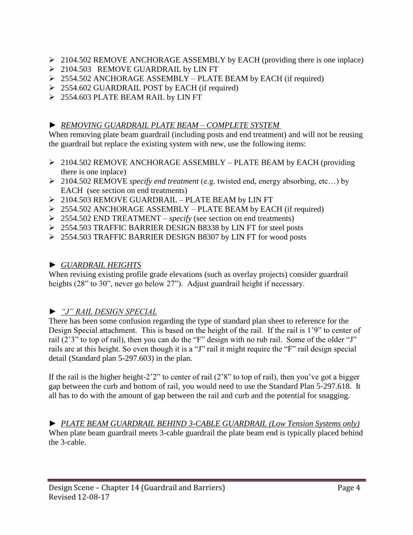
Design Scene – Chapter 14 (Guardrail and Barriers) Revised 12-08-17
Page 4
2104.502 REMOVE ANCHORAGE ASSEMBLY by EACH (providing there is one inplace)
2104.503 REMOVE GUARDRAIL by LIN FT
2554.502 ANCHORAGE ASSEMBLY – PLATE BEAM by EACH (if required)
2554.602 GUARDRAIL POST by EACH (if required)
2554.603 PLATE BEAM RAIL by LIN FT
► REMOVING GUARDRAIL PLATE BEAM – COMPLETE SYSTEM
When removing plate beam guardrail (including posts and end treatment) and will not be reusing
the guardrail but replace the existing system with new, use the following items:
2104.502 REMOVE ANCHORAGE ASSEMBLY – PLATE BEAM by EACH (providing
there is one inplace)
2104.502 REMOVE specify end treatment (e.g. twisted end, energy absorbing, etc…) by
EACH (see section on end treatments)
2104.503 REMOVE GUARDRAIL – PLATE BEAM by LIN FT
2554.502 ANCHORAGE ASSEMBLY – PLATE BEAM by EACH (if required)
2554.502 END TREATMENT – specify (see section on end treatments)
2554.503 TRAFFIC BARRIER DESIGN B8338 by LIN FT for steel posts
2554.503 TRAFFIC BARRIER DESIGN B8307 by LIN FT for wood posts
► GUARDRAIL HEIGHTS
When revising existing profile grade elevations (such as overlay projects) consider guardrail
heights (28” to 30”, never go below 27”). Adjust guardrail height if necessary.
► “J” RAIL DESIGN SPECIAL
There has been some confusion regarding the type of standard plan sheet to reference for the
Design Special attachment. This is based on the height of the rail. If the rail is 1’9” to center of
rail (2’3” to top of rail), then you can do the “F” design with no rub rail. Some of the older “J”
rails are at this height. So even though it is a “J” rail it might require the “F” rail design special
detail (Standard plan 5-297.603) in the plan.
If the rail is the higher height-2’2” to center of rail (2’8” to top of rail), then you’ve got a bigger
gap between the curb and bottom of rail, you would need to use the Standard Plan 5-297.618. It
all has to do with the amount of gap between the rail and curb and the potential for snagging.
► PLATE BEAM GUARDRAIL BEHIND 3-CABLE GUARDRAIL (Low Tension Systems only)
When plate beam guardrail meets 3-cable guardrail the plate beam end is typically placed behind
the 3-cable.
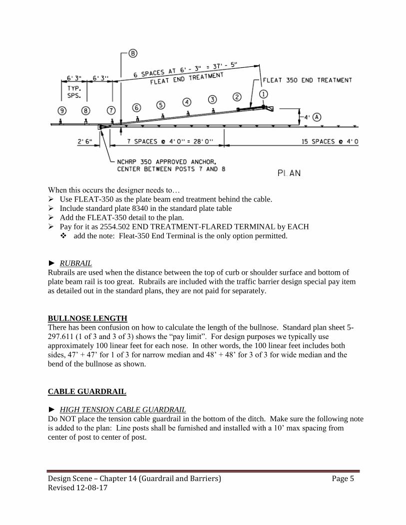
Design Scene – Chapter 14 (Guardrail and Barriers) Revised 12-08-17
Page 5
When this occurs the designer needs to…
Use FLEAT-350 as the plate beam end treatment behind the cable.
Include standard plate 8340 in the standard plate table
Add the FLEAT-350 detail to the plan.
Pay for it as 2554.502 END TREATMENT-FLARED TERMINAL by EACH
add the note: Fleat-350 End Terminal is the only option permitted.
► RUBRAIL
Rubrails are used when the distance between the top of curb or shoulder surface and bottom of
plate beam rail is too great. Rubrails are included with the traffic barrier design special pay item
as detailed out in the standard plans, they are not paid for separately.
BULLNOSE LENGTH
There has been confusion on how to calculate the length of the bullnose. Standard plan sheet 5-
297.611 (1 of 3 and 3 of 3) shows the “pay limit”. For design purposes we typically use
approximately 100 linear feet for each nose. In other words, the 100 linear feet includes both
sides, 47’ + 47’ for 1 of 3 for narrow median and 48’ + 48’ for 3 of 3 for wide median and the
bend of the bullnose as shown.
CABLE GUARDRAIL
► HIGH TENSION CABLE GUARDRAIL
Do NOT place the tension cable guardrail in the bottom of the ditch. Make sure the following note
is added to the plan: Line posts shall be furnished and installed with a 10’ max spacing from
center of post to center of post.

Design Scene – Chapter 14 (Guardrail and Barriers) Revised 12-08-17
Page 6
There has been some problems with the weld not being done properly in the plans and in the field.
Make sure that the detail in the plan shows the weld as shown below.
The following information is part of the High Tension Cable Barrier (HTCB) standards package.
All designers should read the HTCB Technical Memorandum No. 15-08-TS-04 before doing any
HTCB final design. In addition, we suggest that you reference the following information related
to HTCB in your plan as needed.
Standard Plan 5-297.688
Standard Plate for HTCB/Line Post Foundation/Concrete Design 8342
Standard Plate for HTCB/Line Post Foundation/Steel Design 8343
Construction notes:
Consider the following or similar construction notes for use on HTCB projects, if not already
covered elsewhere within your project:
All drainage inlets within 200 feet of any disturbed soil in the median shall be
Provided with appropriate inlet protection prior to disturbance. Inlet protection
Incidental unless otherwise specified in the contract.
All material removed and not reused on this project shall become the property of the contractor
and be disposed of outside MnDOT Right of Way in accordance with Spec. 2106.
Salvage and installation of culvert marker posts are incidental.

Design Scene – Chapter 14 (Guardrail and Barriers) Revised 12-08-17
Page 7
Any required grading for HTCB shall be done before guardrail posts are set.
Roads shall be kept clean of sediment. Use a street sweeper with pick-up type, non-dust generating
power broom as often as necessary to keep roads visibly clean within 24 hours of activity that
generates sediment tracking or before opening the affected lane to traffic, whichever comes first.
All street sweeping work, including street sweeper, shall be incidental.
Post foundations shall be flush with the ground line posts shall be placed plumb.
For all construction activities within designated noxious and invasive weed infested areas as
shown in the plan, see special provisions.
Any required mowing for High Tension Cable Barrier (HTCB) construction is incidental.
► SALVAGE AND INSTALL 3-CABLE GUARDRAIL
On the rare occasions when you want to salvage 3-cable guardrail (Low Tension Systems Only)
and replace the wood posts. It should be paid for as…
2104.503 SALVAGE GUARDRAIL – CABLE by LIN FT, add note to SEQ or tab: Includes
the removal of the wood posts.
2554.603 INSTALL 3-CABLE GUARDRAIL by LIN add note to SEQ or tab: Includes the
Furnish and Install of steel posts.
CONCRETE END POST
The One-Line Bridge Rail End Post as shown on Standard Plan .609 & .619 has been modified to
remove specific structural and reinforcing details regarding the end post. The primary intent of
these standards is to show the guardrail transition and connection to flat faced structures.
Designers will need to work with the Bridge Office to develop specific end post details and
reinforcing on a “case-by-case” basis for all projects that require a new end post. The Office of
Project Management and Technical Support is working with the Midwest Roadside Safety Facility
(State Pooled Fund) to design and test a new “stand alone” end post in accordance with current
crash test requirements (MASH).
GUARDRAIL – POST SEAT
This is used when the guardrail post cannot go as deep as typically required such as over culverts.
This is paid for as 2554.602 GUARDRAIL POST SEAT by EACH
The designer needs to determine if they are using wood posts or steel posts. If they are using
wood posts then Standard Plate 8316 needs to be referenced in the standard plate table. If they are
using steel posts then they need to include a detail in the plan.

Design Scene – Chapter 14 (Guardrail and Barriers) Revised 12-08-17
Page 8
The TYPE 31 guardrail allows for a longer gap between posts (see Standard Plan 5-297.696) so a
post seat may not be needed if using TYPE 31 guardrail.
GUARDRAIL ATTACHMENT TO BARRIER
When attaching guardrail to concrete sloped barrier you need to take into account the connection
to the barrier. The detail below is an example of one such detail you would need to add to the
plan….
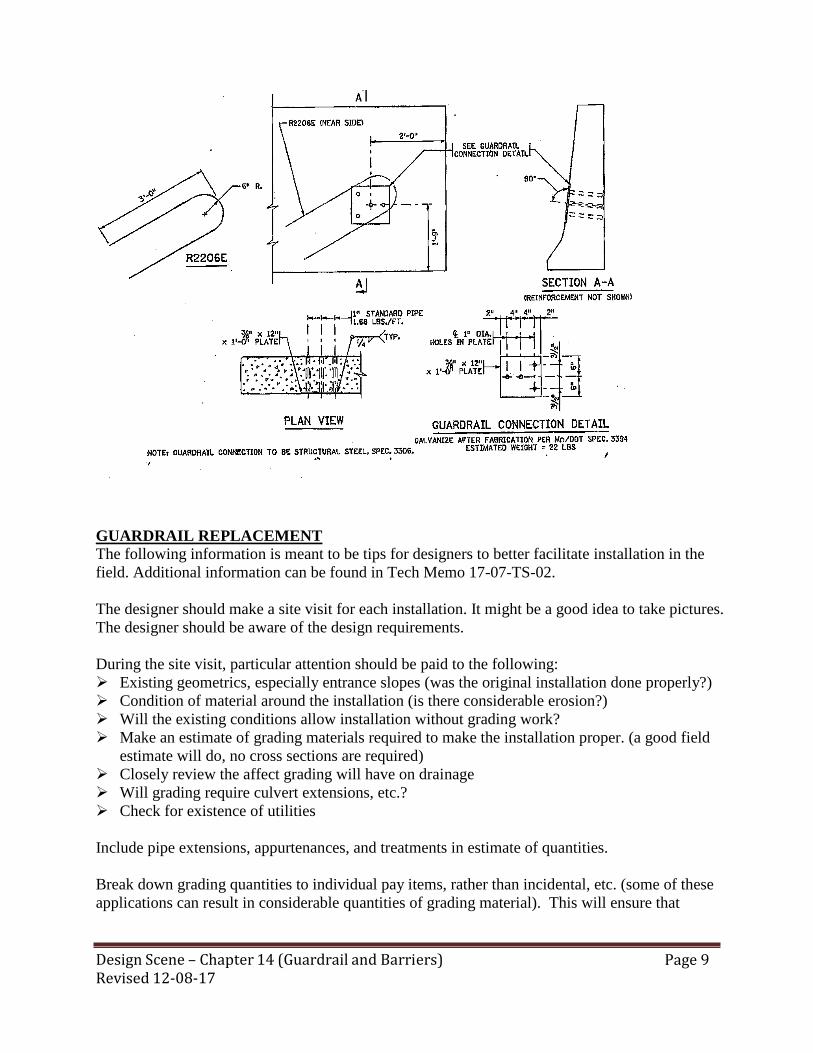
Design Scene – Chapter 14 (Guardrail and Barriers) Revised 12-08-17
Page 9
GUARDRAIL REPLACEMENT
The following information is meant to be tips for designers to better facilitate installation in the
field. Additional information can be found in Tech Memo 17-07-TS-02.
The designer should make a site visit for each installation. It might be a good idea to take pictures.
The designer should be aware of the design requirements.
During the site visit, particular attention should be paid to the following:
Existing geometrics, especially entrance slopes (was the original installation done properly?)
Condition of material around the installation (is there considerable erosion?)
Will the existing conditions allow installation without grading work?
Make an estimate of grading materials required to make the installation proper. (a good field
estimate will do, no cross sections are required)
Closely review the affect grading will have on drainage
Will grading require culvert extensions, etc.?
Check for existence of utilities
Include pipe extensions, appurtenances, and treatments in estimate of quantities.
Break down grading quantities to individual pay items, rather than incidental, etc. (some of these
applications can result in considerable quantities of grading material). This will ensure that
Design Scene – Chapter 14 (Guardrail and Barriers) Revised 12-08-17
Page 10
bidders are actually including this in their bids. It will relieve our project people from paying
premium prices for later contract adjustments.
IMPACT ATTENUATOR BARRELS
The Engineering Cost Data and Estimating Unit is responsible for determining reasonable prices
for supplemental agreement to construction projects. They alerted us to the fact that our past
practice has been to have a pay item for these barrel attenuators as an assembly, perhaps ten (10)
barrels comprising an installation (assembly).
If a second or third installation was required on the project, with a different number of barrels, we
could have 2 or 3 pay items. Also, if these installations are used for traffic control, the contract
reads that the contractor would replace any units at his expense. This is difficult for a contractor to
bid. Also we don’t want to pay for a whole system (10 barrels) if only a couple barrels need
replacing.
We will use impact attenuator barrels, (each). If additional barrels may be needed for replacement,
include a quantity for this and sub note the item on the estimate sheet. The cost of each barrel has
been coming out the same, regardless of the amount of sand/salt required. If a paved area is
required, it should be allowed for separately. The attenuator should be shown in the plans per past
practice, the number of barrels, spacing and weight of sand/salt shown.
IMPACT ATTENUATORS
In order to avoid external conflicts and maintain consistency within MnDOT, we will be changing
how we call out temporary and permanent impact attenuators on our traffic control plans.
We will be specifying whether they are TL3s or TL2s (test levels) instead of posted speed limits.
All Temporary Impact Attenuators that are to be placed on roads with the speeds of 50 mph or
greater will now be TL3 and those that are 45 mph or less shall be TL2. These will be noted on
our Pay Item Tabulation sheets like we have been doing. If the project requires both TL3 and TL2
attenuation, then they should be labeled on the plan sheets for clarification.
The plan should also contain a note stating if it is a temporary or permanent installation.
Examples: Same test level for all…

Design Scene – Chapter 14 (Guardrail and Barriers) Revised 12-08-17
Page 11
No need to label attenuators as they are all the same.
Example: Different test levels and temporary situation…
TRAFFIC TABULATION TC
DESCRIPTION UNIT TOTAL
PORTABLE PRECAST CONCRETE BARRIER DESIGN 8337 LIN FT 400
PORTABLE PRECAST CONCRETE BARRIER DESIGN 8337-ANCHORED LIN FT 792
IMPACT ATTENUATOR ① ASSEMBLY 4
TRAFFIC CONTROL LUMP SUM 1
MEDIAN BARRIER DELINEATOR ② EACH 40
REMOVABLE PREFORM PAVEMENT MARKING TAPE ③ LIN FT 5798
REMOVABLE PREFROMED PLASTIC MASK (BLACK) LIN FT 3470
① TL3, TEMPORARY
② 20 WHITE, 20 YELLOW, ALL ONE WAY
③ 3052 LIN FT OF 4" SOLID LINE WHITE, 2746 LIN FT OF 4" SOLID LINE YELLOW
TRAFFIC TABULATION TC
DESCRIPTION UNIT TOTAL
PORTABLE PRECAST CONCRETE BARRIER DESIGN 8337 LIN FT 400
PORTABLE PRECAST CONCRETE BARRIER DESIGN 8337-ANCHORED LIN FT 792
IMPACT ATTENUATOR ① ASSEMBLY 4
TRAFFIC CONTROL LUMP SUM 1
MEDIAN BARRIER DELINEATOR ② EACH 40
REMOVABLE PREFORM PAVEMENT MARKING TAPE ③ LIN FT 5798
REMOVABLE PREFROMED PLASTIC MASK (BLACK) LIN FT 3470
① 2-TL2 and 2-TL3, TEMPORARY
② 20 WHITE, 20 YELLOW, ALL ONE WAY
③ 3052 LIN FT OF 4" SOLID LINE WHITE, 2746 LIN FT OF 4" SOLID LINE YELLOW

Design Scene – Chapter 14 (Guardrail and Barriers) Revised 12-08-17
Page 12
Need to label all attenuators as to what level they are.
Example: Different test levels and permanent situation, you need to label as different attenuators
both on the table and in the plan view (see example above)…
PORTABLE PRECAST CONCRETE BARRIER
PPCB, (Type F), Standard Plate No. 8337 is for temporary usage only. It is not designed to be used
for a permanent barrier.
The Type F PPCB is required on many bridge construction sites and their immediate approaches
(normally, (120 ft.) adjacent to the bridge end) when the PPCB is designated as the means of
protecting the construction site. The Type F barrier will also be required along deep drop-offs
immediately adjacent to lanes used to carry traffic. See the MnMUTCD Table 6F-5 for more
information. Type F PPCB is required for major maintenance work on bridges, which will take a
considerable length of time and if a positive barrier is needed.
TRAFFIC TABULATION TC
DESCRIPTION UNIT TOTAL
PORTABLE PRECAST CONCRETE BARRIER DESIGN 8337 LIN FT 400
IMPACT ATTENUATOR ① ASSEMBLY 2
IMPACT ATTENUATOR NO 1 ② ASSEMBLY 2
TRAFFIC CONTROL LUMP SUM 1
MEDIAN BARRIER DELINEATOR ③ EACH 40
① TL-3 PERMANENT
② TL-2 PERMANENT
③ 20 WHITE, 20 YELLOW, ALL ONE WAY

Design Scene – Chapter 14 (Guardrail and Barriers) Revised 12-08-17
Page 13
Adequate flare (desirably about 1:10) or end protection, such as a crash cushion, to prevent impact
with exposed barrier ends must continue to be provided.
SHORT RADIUS GUARDRAIL
Whenever the guardrail includes a short radius around an entrance, driveway, or side road it will
require a special short radius detail. Only wood posts may be used for this installation, NO
STEEL POSTS and NO TYPE 31.
For TYPE 31 connection see article in this chapter under “TYPE 31
GUARDRAIL…CONNECTING TO SHORT RADIUS” for more information.
The detail is considered an unapproved standard detail and shows the use of wood posts. This
would require the use of item 2554.503 TRAFFIC BARRIER DESIGN A8307 or 2554.503
TRAFFIC BARRIER DESIGN B8307 by the LIN FT.
It can be found internally at….
http://ihub/designsupport/standards/design.html
For those outside of MnDOT please contact your project manager to get a copy.

Design Scene – Chapter 14 (Guardrail and Barriers) Revised 12-08-17
Page 14
STIFFENED GUARDRAIL
When nested rail and/or half or quarter post spacing is required use the standard pay item for
guardrail and add a note to the SEQ or tab: Item includes additional posts and/or nested rail from
Station XX+XXX to Station XX+XXX.
When stiffening guardrail, use the following guidance when location the additional posts (Nesting
is not an option for TYPE 31 guardrail).
Half post spacing (posts every 3’-1.5”)
Begin half post spacing 12.5’ before hazard
End half post spacing – 12.5’ past hazard

Design Scene – Chapter 14 (Guardrail and Barriers) Revised 12-08-17
Page 15
Quarter spacing (posts every 1’- 6.75”)
Start half post spacing 25’ before hazard
Start quarter post spacing 12.5’ before hazard
End quarter post spacing 12.5’ past hazard
End half post spacing 25’ past hazard
Ending Guardrail - How far to take the guardrail beyond the hazard when shielding is not required
in the opposite traffic direction? There is currently no statewide consensus on this. The guidance
is different for 8338 vs. Type 31. For the interim we would recommend that 12’-6” be used as a
minimum for type 8338, and that 16’-2” be used for Type 31 (12’-6” + 3’-8”).
T-BARRIER BRIDGE CONN DES 8318
The T-Barrier Bridge Connection is used when connecting guardrail to a bridge rail or concrete
structure. It is included in the pay item for Traffic Barrier Design Special or AGT and should not
be paid for separately in those cases.
If there is guardrail on the downstream end of a bridge and it is not a design special attachment
then the pay item 2554.602 T-BARRIER BRIDGE CONN DES 8318 by EACH should be
included in the tab and SEQ.
In both cases the standard plate table should reference 8318.

Design Scene – Chapter 14 (Guardrail and Barriers) Revised 12-08-17
Page 16
TYPE 31 VS B8338 GUARDRAIL
With the new Tech Memo #17-07-TS--2 there has been some confusion on when you have to use
the TYPE 31 guardrail and when you can still use the B8338 when working on the existing
guardrail.
If it is a preservation project and no bridge work is being done and the existing guardrail is in good
condition (per tech memo) then the B8338 guardrail may remain as is.
If the preservation project extends the life of the surface more than 10 years, or increases the
height of the surface such that the existing guardrail height will be less than 27” the guardrail
should be upgraded to meet the current MASH standard.
If there is a proposed project that will replace the existing guardrail within 10 years then the
B8338 guardrail may be used in the interim as long as it was up to standards.
TYPE 31 GUARDRAIL
There has been much confusion regarding the design/use of the TYPE 31 guardrail. Hopefully the
following will help to alleviate some of that confusion.
► REMOVE APPROACH GUARDRAIL TRANSITION (AGT)
When removing AGT pay for it as…
2104.503 REMOVE GUARDRAIL – PLATE BEAM by LIN FT and add the note: Includes
AGT.
► GUARDRAIL END TREATMENTS
Guardrail must be in tension to work, this is true for both plate beam and cable. Therefore, it
MUST have tension on both ends either by an anchorage assembly, design special, and/or end
treatment. The designer needs to notice if both ends of the guardrail are addressed. So if there isn’t
an end treatment, is there an anchorage assembly or design special?
TYPE 31 End Terminals
Tangent Terminals…The preferred MnDOT terminal is the tangent terminal. MnDOT
now has two design details and associated approvals on the APL web page and both need
to be listed in the plan. If you only choose one of the terminals it will require a project
specific PIF. These terminals are MASH tested terminals.
Flared terminal…MnDOT does not have an approved flared terminal for TYPE 31. If a
flared terminal is preferred, the FLEAT-MGS and SRT-350 31 are NCHRP 350 approved
end terminals for TYPE 31 guardrail.
There are details available on the server for the following end treatments, which should be
placed into the plans. These details are propriety end treatments and should not be
modified or signed. These details are located in Projectwise Design Detail Locations. If
outside of MnDOT you will need to contact the MnDOT project manager to obtain the
details.
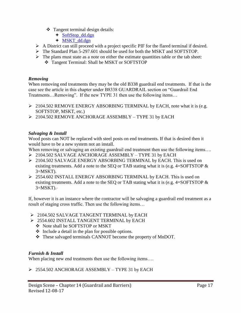
Design Scene – Chapter 14 (Guardrail and Barriers) Revised 12-08-17
Page 17
Tangent terminal design details:
SoftStop_dd.dgn
MSKT_dd.dgn
A District can still proceed with a project specific PIF for the flared terminal if desired.
The Standard Plan 5-297.601 should be used for both the MSKT and SOFTSTOP.
The plans must state as a note on either the estimate quantities table or the tab sheet:
Tangent Terminal: Shall be MSKT or SOFTSTOP
Removing
When removing end treatments they may be the old B338 guardrail end treatments. If that is the
case see the article in this chapter under B8338 GUARDRAIL section on “Guardrail End
Treatments…Removing”. If the new TYPE 31 then use the following items…
2104.502 REMOVE ENERGY ABSORBING TERMINAL by EACH, note what it is (e.g.
SOFTSTOP, MSKT, etc.)
2104.502 REMOVE ANCHORAGE ASSEMBLY – TYPE 31 by EACH
Salvaging & Install
Wood posts can NOT be replaced with steel posts on end treatments. If that is desired then it
would have to be a new system not an install.
When removing or salvaging an existing guardrail end treatment then use the following items….
2104.502 SALVAGE ANCHORAGE ASSEMBLY – TYPE 31 by EACH
2104.502 SALVAGE ENERGY ABSORBING TERMINAL by EACH. This is used on
existing treatments. Add a note to the SEQ or TAB stating what it is (e.g. 4=SOFTSTOP &
3=MSKT).
2554.602 INSTALL ENERGY ABSORBING TERMINAL by EACH. This is used on
existing treatments. Add a note to the SEQ or TAB stating what it is (e.g. 4=SOFTSTOP &
3=MSKT).
If, however it is an instance where the contractor will be salvaging a guardrail end treatment as a
result of staging cross traffic. Then use the following items…
2104.502 SALVAGE TANGENT TERMINAL by EACH
2554.602 INSTALL TANGENT TERMINAL by EACH
Note shall be SOFTSTOP or MSKT
Include a detail in the plan for possible options.
These salvaged terminals CANNOT become the property of MnDOT.
Furnish & Install
When placing new end treatments then use the following items….
2554.502 ANCHORAGE ASSEMBLY – TYPE 31 by EACH
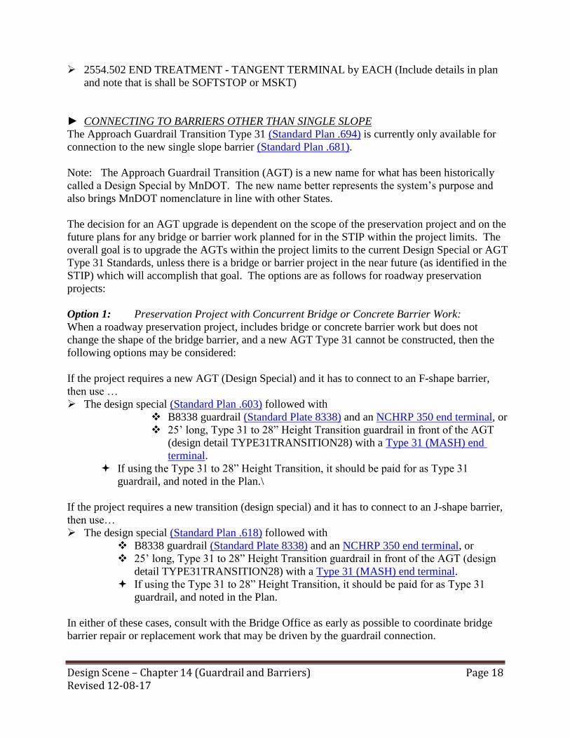
Design Scene – Chapter 14 (Guardrail and Barriers) Revised 12-08-17
Page 18
2554.502 END TREATMENT - TANGENT TERMINAL by EACH (Include details in plan
and note that is shall be SOFTSTOP or MSKT)
► CONNECTING TO BARRIERS OTHER THAN SINGLE SLOPE
The Approach Guardrail Transition Type 31 (Standard Plan .694) is currently only available for
connection to the new single slope barrier (Standard Plan .681).
Note: The Approach Guardrail Transition (AGT) is a new name for what has been historically
called a Design Special by MnDOT. The new name better represents the system’s purpose and
also brings MnDOT nomenclature in line with other States.
The decision for an AGT upgrade is dependent on the scope of the preservation project and on the
future plans for any bridge or barrier work planned for in the STIP within the project limits. The
overall goal is to upgrade the AGTs within the project limits to the current Design Special or AGT
Type 31 Standards, unless there is a bridge or barrier project in the near future (as identified in the
STIP) which will accomplish that goal. The options are as follows for roadway preservation
projects:
Option 1: Preservation Project with Concurrent Bridge or Concrete Barrier Work:
When a roadway preservation project, includes bridge or concrete barrier work but does not
change the shape of the bridge barrier, and a new AGT Type 31 cannot be constructed, then the
following options may be considered:
If the project requires a new AGT (Design Special) and it has to connect to an F-shape barrier,
then use …
The design special (Standard Plan .603) followed with
B8338 guardrail (Standard Plate 8338) and an NCHRP 350 end terminal, or
25’ long, Type 31 to 28” Height Transition guardrail in front of the AGT
(design detail TYPE31TRANSITION28) with a Type 31 (MASH) end
terminal.
If using the Type 31 to 28” Height Transition, it should be paid for as Type 31
guardrail, and noted in the Plan.\
If the project requires a new transition (design special) and it has to connect to an J-shape barrier,
then use…
The design special (Standard Plan .618) followed with
B8338 guardrail (Standard Plate 8338) and an NCHRP 350 end terminal, or
25’ long, Type 31 to 28” Height Transition guardrail in front of the AGT (design
detail TYPE31TRANSITION28) with a Type 31 (MASH) end terminal.
If using the Type 31 to 28” Height Transition, it should be paid for as Type 31
guardrail, and noted in the Plan.
In either of these cases, consult with the Bridge Office as early as possible to coordinate bridge
barrier repair or replacement work that may be driven by the guardrail connection.

Design Scene – Chapter 14 (Guardrail and Barriers) Revised 12-08-17
Page 19
Additionally, bridge and roadway designers will need to coordinate for guardrail connections to
any other bridge barrier type.
Option 2: Preservation Project with Non-Concurrent Bridge or Concrete Barrier Work:
When a roadway preservation project includes an existing bridge or concrete connection within the
projects limit, but does not include bridge or concrete barrier work, then the following guidance
will apply:
If there is a separate bridge (or barrier) project programmed in the near future (as identified in the
STIP) concerning the connection (AGT) point in question, then the guardrail can be reconnected
to the end post or bridge rail with the original design standard in place at the time of its
construction. This option can be used if the connection system is fully inspected and that it’s
found to be in an acceptable condition.
If there is not a bridge (or barrier) project programmed in the STIP, or if the system elements are
in disrepair, then the Bridge Office will need to be consulted early on in the project scoping
process to investigate alternative design variations.
► CONNECTING TO BULLNOSE
When connecting the bullnose to the TYPE 31 guardrail use the thrie beam bullnose transition to
Traffic Barrier Type 31 design detail (BULLNOSE TO TYPE 31). The 6’3” transition section
(between posts 10 and 11) are paid for as TYPE 31 guardrail. The plan will also need to include
the Standard Plan sheet 5-297.695.
► CONNECTING TO SHORT RADIUS
Designers can only attach Type 31 to the short radius after the vertical transition at position #1, as
indicated on the drawing below (where the curved section ends, on the main roadway side of the
short radius detail).

Design Scene – Chapter 14 (Guardrail and Barriers) Revised 12-08-17
Page 20
► TYPE 31 END TREATMENT SHOWN IN PLAN VIEW
There has been confusion on how to show this in the plan as the two end treatments (SOFTSTOP
& MSKT) are of different lengths. In the past we would show the stationing to the end of the end
treatment but that is not the case for the Type 31 guardrail with tangent terminals.
In the plan view show a + station where the Type 31 guardrail ends and the end treatment begins.
This may not necessarily be the length of need as a portion of the length of need is covered in the
end treatment pay item (approximately 34’- 4.5”). It is desirable to show the end treatment with a
different icon. For example below the TYPE 31 ends at 122+71 which is where the end treatment
begins.
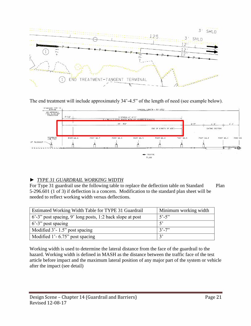
Design Scene – Chapter 14 (Guardrail and Barriers) Revised 12-08-17
Page 21
The end treatment will include approximately 34’-4.5” of the length of need (see example below).
► TYPE 31 GUARDRAIL WORKING WIDTH
For Type 31 guardrail use the following table to replace the deflection table on Standard Plan
5-296.601 (1 of 3) if deflection is a concern. Modification to the standard plan sheet will be
needed to reflect working width versus deflections.
Working width is used to determine the lateral distance from the face of the guardrail to the
hazard. Working width is defined in MASH as the distance between the traffic face of the test
article before impact and the maximum lateral position of any major part of the system or vehicle
after the impact (see detail)
Estimated Working Width Table for TYPE 31 Guardrail Minimum working width
6’-3” post spacing, 9’ long posts, 1:2 back slope at post 5’-5”
6’-3” post spacing 5’
Modified 3’- 1.5” post spacing 3’-7”
Modified 1’- 6.75” post spacing 3’

Design Scene – Chapter 14 (Guardrail and Barriers) Revised 12-08-17
Page 22
.
Design Scene – Chapter 15 (Fencing) Revised 10-30-17
Page 1
CHAPTER 15: FENCING
CHAIN LINK FENCE PAY ITEMS
When placing new chain link fence the METAL BRACE ASSEMBLIES are included in the cost of
the chain link fence unless a separate pay item is included in the SEQ.
However, the ELECTRICAL GROUND is always paid for separately. Be sure to include a pay item
for this in the SEQ.
CHAIN LINK FENCE TOP RAIL Whenever you are doing a project and you have chain link fence in the clear zone you should check
that the top rail is cable and not a steel pole. There has been a case were the pole has been known to
pierce a motorist. If you need to replace the top rail post with cable use pay item 2557.603
REPAIR FENCE by the LIN FT.
FENCE LOCATION See the Road Design Manual Figure 11-9.06A for diagrams of where to place fencing.
SNOW FENCING Blowing and drifting snow for most Minnesotans that phrase conjures up images of windblown
landscapes where roadways disappear, weather forecasters warn of life threatening conditions, and
highway heroes drive big orange trucks. On an average winter Minnesota taxpayers spend 100
million dollars annually on snow and ice control. MnDOT alone typically spends 41 million dollars
annually on snow and ice control.
Blowing and drifting snow is a transportation efficiency and safety concern. The effects have
impact on Minnesota’s economy as well as it’s public safety. Within MnDOT a snow control
steering committee was established to assess MnDOT’s role and internal expectations and advocate
the tools available to solve the blowing and drifting snow problem. What are the tools available for
solving the blowing and drifting snow problem?
The tools available include living snow fences, structural snow fencing, raising the grade of the
roadway, and flattening the backslopes along the roadway. Each one of these choices needs to be
balanced among personal, social, economic, and environmental values in order to select the best
solution.
A survey of county and state snow plow operators revealed that there are 1,000 mi. of problem
roadway, 550 mi. on the county highway system and 450 mi. on the state trunk highway system that
require retrofitting to solve the blowing and drifting snow problem. Retrofitting a problem section
of roadway after the design and construction of the roadway is completed presents many challenges.

Design Scene – Chapter 15 (Fencing) Revised 10-30-17
Page 2
Those challenges deal largely with the logistics having to go back, a second time, to the adjacent
landowners and acquire a property right to implement a snow control practice. Also, traffic flow is
enhanced for the traveling public when we solve the blowing and drifting snow problem along an
entire corridor.
The first step in solving snow deposition problems is to identify sections along the roadways that the
highway maintenance crews know are subjected to blowing and drifting snow. Snowplow operators
are also helpful because they are familiar with what types of problems are typically encountered on
a given section of roadway, such as upwind drifting, downwind drifting, poor visibility, or slush and
ice buildup on the road surface.
More information regarding snow fences can be found at…
www.dot.state.mn.us/environment/livingsnowfence/index.html
Design Scene – Chapter 16 (Traffic) Revised 12-08-17
Page 1
CHAPTER 16: TRAFFIC
ADVANCE WARNING SIGN SPACING The Advance Warning Sign Spacing for 0-30 mph has been reduced from 300 feet to 100
feet. This is more in line with the Federal MUTCD and accounts for more limited space in urban
type jobs where the speed limit is 30 or less.
CENTERLINE MARKINGS When paying for the double centerline yellow markings do not pay for them as two 4” solid line
white but rather use the pay item…
2016 Spec…2582.502 4” DOUBLE SOLID LINE –material by LIN FT
2018 Spec…2582.503 4” DOUBLE SOLID LINE – material by LIN FT
INTERIM PAVEMENT MARKINGS – ITEM 2580 There has been confusion regarding the use of this pay item and the quantities to be included. A
group has been reviewing the use of interim markings and several problems have been identified.
This pay item should only be used for same day pavement markings to be placed on bituminous
lifts and milled surfaces. Striping for detours or full striping of the project for suspensions should
be paid for under pavement marking (2582) pay items. (Normally paint).
Interim markings do not include edge lines and the length of the skip will be 5 ft. with a 45 ft. gap.
Quantities must include centerline marking for each lift including any milled surfaces. For two
lane, two way roads, quantities for the no passing zones need to be included. These quantities are
kept on record in the District Traffic Offices. When being paid for by the linear foot, the plan
needs to indicate how many lifts were estimated, the amount of solid yellow line, yellow broken
line (skip) and white broken line (skip).
If the interim markings are being paid for by the lump sum this information is not included in the
plan but will be in the Projectwise restricted file folder.
In either situation, the plan must contain the detail for the interim pavement markings.
INTERIM STRIPING TYPICAL
The interim striping typical can go in either the Traffic control section or the permanent pavement
marking section. It should only be in one section and must be the typical as shown on the striping
typical website. Make sure that the pay item is included in the Statement of Estimated Quantity.

Design Scene – Chapter 16 (Traffic) Revised 12-08-17
Page 2
MULTI COMP VS EPOXY
The pay item for Epoxy has changed. MnDOT has maintained a Qualified Products List for Epoxy
pavement markings; however, many of the products on this list are not ‘true epoxies’, one is a modified
urethane and others are modified epoxies. In addition, there are other pavement marking materials for
which a separate QPL was maintained (such as Polyurea). OTST decided to combine these into a Multi-
Component list.
The new 2018 spec book has changed the 3590 specification to Multi-Component Liquid Pavement
Markings and the pay item had to change as well.
Thus, when using the 2018 spec book, do not use EPOXY as the pay item – use MULTI COMP instead.
ONE DIRECTION LARGE ARROW The Type III barricade with a One-Direction Large Arrow at the end of the merging taper and
another identical assembly at the beginning of the taper (if a Flashing Arrow Board was not used)
has essentially been what Minnesota has been using for lane closures since Appendix B was
published.
However, there was no language in TTC (Temporary Traffic Control) chapter of the MN
MUTCD that allowed this use. The One-Direction Large Arrow is governed by language in
Warning Signs Chapter 2C (2C.12) that limits its use to delineating a change in horizontal
alignment for curves. Language was drafted for consideration by the Minnesota Committee on
Uniform Traffic Control Devices, but it was found to not be in compliance with the Federal
MUTCD.
Per a recent clarification from the FHWA, it cannot be used for merging tapers, though it will still
be used for shifting tapers. Therefore, for all projects submitted for the January 26, 2018
letting or later must following the new layout as described below.
Due to this clarification, the Field Manual Committee has developed new layout, instead of the
One Direction Large Arrow on the Type III barricade at the end of the taper, a LANE CLOSED
(black on White) sign will be used (required when speed limit is 45 mph or greater). If the
Flashing Arrow Board is not used (it is required when speed limit is 45 mph or greater), a
MERGE with Arrow sign will be placed at the beginning of the taper.

Design Scene – Chapter 16 (Traffic) Revised 12-08-17
Page 3
PREVIOUS METHOD-
NO LONGER ALLOWED NEW METHOD
PAVEMENT MARKING TYPICALS
The Pavement Marking Typicals for projects follow a general style and format. The reference
files are available in PDF and DGN formats to be imported in the pavement marking plans project
border. They can be found at….
http://www.dot.state.mn.us/trafficeng/pavement/typicaldetail/index.html
The designer should be aware that when adding some of these typicals in the .DGN file it may
look as though there is some overwriting occurring. It will self-correct when loaded into
ProjectWise with MnDOT fonts. This will also self-correct when printed with MnDOT print cues
so do not be concerned about it.
When the pavement marking typicals are placed on a sheet with a signature block, the signature is
affirming the use of a specific pavement marking typical which follows MnDOT’s Traffic
Engineering Manual. The signature is not intended to imply that the Designer designed that
specific pavement marking typical.
Design Notes
The Designer notes should be removed from the typicals prior to being placed in the plan. The
designer notes and asterisk are on the “CAPT BLK” level. If they turn off that level all of that
should disappear.

Design Scene – Chapter 16 (Traffic) Revised 12-08-17
Page 4
If revising the typical based on an option in the designer notes such as using a 6” marking instead
of a 4” marking, a modification date and initial is not required. As this is allowed by MnDOT’s
Traffic Engineering Manual, this is not considered a modification and the revision can be made
without following the modification guidelines below.
Modifying Typicals
Most of the typicals are used in the plans as is, but on occasion there is a need to change or modify
a typical. The designer is allowed to make changes if allowed by the Minnesota Manual on
Uniform Traffic Control Devises. If a typical is modified in a way that is not proved in the
designer notes, follow the process below. If a typical contains information not associated with
your project, it is optional for designers to cross out the undesired details/information, do NOT
delete the undesired details/information from the typical.
Fill in the modified date and designer initial in the bottom corner of the typical.
Identify the changes made to the typicals
Label the changes using Italicized text and
Add a note to the typical above the PUBLISHED DATE: *DENOTES
MODIFICATION FROM STANDARD TYPICAL
Use the MicroStation custom line style StdsPlnMod to place a double line
(thick/thin) box around the text to highlight/identify the modification(s).
See example below…

Design Scene – Chapter 16 (Traffic) Revised 12-08-17
Page 5

Design Scene – Chapter 16 (Traffic) Revised 12-08-17
Page 6
PAVEMENT MESSAGES
Pavement messages are now paid for by the square foot. Individual messages (placing and
removing) should be listed in a tab. The following chart shows square areas for both removal of
messages, which includes a larger area around the marking, and installation, which only includes
the area of material installed. The chart can be found at…
http://www.dot.state.mn.us/trafficeng/pavement/typicaldetail/index.html
The reason that the removal areas are larger than the placement areas is because the removal is a
rectangular area.
It is easier for the contractor to grind out a rectangle than the shape.
If only the shape is removed, that removed shape may still be seen at night or in wet
conditions.

Design Scene – Chapter 16 (Traffic) Revised 12-08-17
Page 7
RADIUS CORNERS ON TYPE D SIGNS
Currently, there is a standard note that is placed on the Type D Sign Panel Layouts in the Signing
Plan. It states: “Corners of the sign panels extending beyond the border shall not be trimmed.”
The MNMUTCD allows for corners of sign panels to be trimmed. Please remove the above note
from all future plans for Type D signs.
It is important to note that by removing the note in the construction signing plan, it does not mean
that all MnDOT Type D signs are required to have the corners trimmed. It simply means that if
Type D signs are manufactured with the corners trimmed MnDOT will accept them.
RAISED PAVEMENT MARKERS TEMPORARY
When including temporary raised pavement markers in the plan, show only one pay item. “Raised
Pavement Markers Temporary” - and add footnote to the item indicating how many are one-way,
two-way, and what color. We have a specification to attach to the proposal that only includes this
pay item. (There is very little difference in cost for the different types.)
REMOVABLE PAVEMENT MESSAGES
The various message items 2581.602 PAVEMENT MESSAGE (_____) REMOVABLE POLY
PREFORM by the EACH have been changed to one item 2581.618 REMOVABLE
PREFORMED PAVEMENT MESSAGE TAPE by the SQ FT to match the permanent message
items.
RUMBLE STRIPES
Any Wet Reflective pavement marking needs to be recessed somehow. This is due to the fact that
the Wet Reflective markings utilize larger sized reflective media that will typically be scraped off
in the winter months by plows – leading to little-to-no retroreflectivity after some snow plow
operations. As a reminder, only liquid Wet Reflective pavement markings can be placed in a
rumble.
This can become even more confusing when placed in a rumble. When a Wet Reflective marking
is placed in a sinusoidal rumble (which is installed fully below the pavement surface) or placed in
a centerline area that is recessed by installing a chip seal only in the travel lanes, it is already
recesses and does NOT need to be ground in further. Therefore, the pay item for these pavement
markings should just be (WR) not Ground In (WR).
The rectangular corrugated rumble is made by grinding out corrugations every 7 inches out of the
pavement, which leaves the space in between the corrugations alone. If a Wet Reflective
pavement marking is placed on a rectangular corrugated rumble, then the reflective media between
the rumbles will be scraped off. Therefore, it is recommended that these Wet Reflective pavement
markings also be ground in…Ground In (WR).
Design Scene – Chapter 16 (Traffic) Revised 12-08-17
Page 8
ALTERNATE PEDESTRIAN ROUTE (APR)
A wide range of pedestrians can be expected at work sites, including the young, elderly, and
people with disabilities such as hearing, visual, or mobility. These pedestrians need a clearly
delineated and usable travel path.
If the TTC zone affects the movement of pedestrians, adequate pedestrian access and walkways
shall be provided. If the TTC zone affects an accessible and detectable pedestrian facility, the
accessibility and detectability shall be maintained along the alternate pedestrian route. Layouts are
available in the Minnesota Temporary Traffic Control Field Manual and Traffic Control Templates
are available on MnDOT’s Temporary Traffic Control Plan Template Sheets website – at
http://www.dot.state.mn.us/trafficeng/workzone/ttctemplates.html .
Consideration should be made to separate pedestrian movements from both work site activity and
motor vehicle traffic.
It is strongly encouraged to pay for this as…
2563.601 ALTERNATE PEDESTRIAN ROUTE by the LUMP SUM.
However, the ADA Office recommends making APR on mill and overlay projects incidental
unless there are multiple curb line changes which require removal of large areas of pavement.
When APR is not practical pinch the staging timelines so that pedestrian facilities are interrupted
for as little time as possible.
TRAFFIC CONTROL TABULATION
Traffic control items that are included with the lump sum should not show quantities on the
tabulation. This information will be supplied in the current tabulated or listed format via a stand
alone document to the Cost Estimating Engineer and the Project Design Services the Projectwise
restricted file foder only, at the time of project submittal. The Preliminary Estimate and Data Base
file (*.mdb) will be located in the specific projects ProjectWise location (a right protected folder),
with AD group name of “DxEstimates” and a Folder name of “Estimates_Restricted” which
restricts access for anyone except newly established AD group (Ex. Design Engineer, Lead
Designer & District Cost Estimating Engineer).
Quantities can only be given in the plan for the items which are being paid for separately.
However, the items which are paid for separately (not part of the lump sum) should be shown as a
tabulation for traffic control and noted as being paid for separately. Items such as, but not limited
to …
2533 PORTABLE PRECAST CONRETE BARRIER DES 8337
2554 IMPACT ATTENUATOR BARRELS
2554 IMPACT ATTENUATOR
2563 PORTABLE CHANGEABLE MESSAGE SIGN
2563 RAISED PAVEMENT MARKER TEMPORARY
2563 TUBE DELINEATOR
2582 TEMPORARY STRIPING

Design Scene – Chapter 16 (Traffic) Revised 12-08-17
Page 9
WET REFLECTIVE MARKINGS
There has been a request to have specific pay items for the wet reflective pay items so that they
can track where these items are used and to obtain historical price data on them.
Therefore, when the plan contains wet reflective pay items the following should be used on the
Statement of Estimated Quantities….
Wet reflective items are required to be recessed per MnDOT Standard Specifications and
MnDOT’s Traffic Engineering Manual.

CHAPTER 17: CROSS SECTIONS
CROSS SECTION/UTILITIES A reminder that when your plan design requires that utilities be shown on the cross sections you need to also show the existing and new R/W. These requirements are stated in the Utilities
manual which can be found at….
www.dot.state.mn.us … MnDOT A to Z…U…Utility Relocation…In the chapter for “Utility
coordination process” click on the link for the “Utility Accommodation and Coordination
Manual”
EARTHWORK ON CROSS SECTIONS Just some miscellaneous comments on cross section development.
If it is easier to computer plot cross sections with a one inch square grid, it is acceptable. It
would be helpful to name an elevation noted in the sketch, such as a ditch elevation.
Another general comment on cross sections. Generally it is better if earthwork quantities are
shown on the cross sections. This provides a general check on the quantities.
Design Scene – Chapter 17 (Cross Section) Page 1 Revised 08-03-15

Design Scene – Chapter 18 (General Notes and Miscellaneous) Page 11 Revised 12-08-17
CHAPTER 18: GENERAL NOTES and MISCELLANEOUS
ADDENDUM SIGNATURE BLOCK A signature block is required on a plan sheet that is added or revised by an addendum. When a
new plan sheet is added to the plan by addendum, the sheet shall be numbered with “A”, “B”,
“C” etc. (e.g. Sheet No. 63A of 63). Revised plan sheets: When a plan sheet is deleted and a
revised plan sheet substituted by an addendum, the revised sheet shall be numbered with a “R”
(e.g. Sheet No. 62R of 62).
CHANGING PROJECT SCOPE Projects are usually reviewed in the preliminary design stage for effects on historical or
archaeological properties. If the project design has been modified since that review such that
project limits or areas of construction have been expanded, the project should be submitted for
re-review. Contact you District Preliminary Design Engineer at least several months in advance
of the letting date in order to avoid last minute problems, which could delay the letting.
Designers need to check that the work and limits outlined on the plan match the STIP. The STIP
may be updated periodically throughout the course of the year for project additions,
advancements, changes in scope, cost, and other types of changes. These changes are
accomplished either by a Formal STIP Amendment or an Administrative STIP Modification.
Every effort should be made to keep Formal STIP Amendments and Administrative STIP
Modifications to a minimum.
For guidance on the type of amendment and the process please check out the STIP Guidance
website at….
http://www.dot.state.mn.us/planning/program/pdf/stip/stip_amendment_guidance_eff_04-15-
15.pdf
CONTRACTORS CROSSING OF RAILROADS The following article was written by the Railroad Negotiations Section to provide additional
guidance to designers for contractors crossing of railroad tracks.
“The designer should review the need for a contractor to cross the railroad tracks. This
information must be passed on to the Railroad Administration Office in order that agreements or
other arrangements can be made. Please note that the agreement process can take three to six
months. When proper notice is not provided, lettings can be delayed.”
When a highway contractor works on railroad property, such as where bridge construction would
involve equipment working on or crossing railroad property, the contractor cannot trespass on
railroad property or any other private property without meeting some special requirements.
It is the designer’s responsibility to determine whether or not the contractor will be required to
work on railroad property - (which is outside the right-of-way) and to notify the Land

Design Scene – Chapter 18 (General Notes and Miscellaneous) Page 12 Revised 12-08-17
Management and Administration Office of the potential problem so that agreements, if
necessary, can be executed prior to bid letting.
DEFINITION OF INSTALL
There has been some confusion recently on the definition of “Install”. Whenever the word
“install” (or variation thereof) is used it implies that the materials are being supplied (or are from
salvaged items). If this is the case then using the word “install” by itself is correct.
If however, the materials are not being supplied (or are not from salvaged items) then one of the
following words (and/or their variation) should be used…. place, construct, furnish & install.
DESIGN EXCEPTIONS
A design exception occurs when a highway project design includes geometric design elements
that fail to satisfy criteria set forth as policy by MnDOT and/or the Federal Highway
Administration (FHWA). Failure of the design to meet the standard for any of the 13 Critical
Design Elements requires approval of a formal design exception.
It is expected that …
There will be early coordination
The design exception does not duly degrade the safety and operational performance of the
roadway
The compatibility with the adjacent roadway segments will be maintained
The design exception will exercise good design practice and engineering judgment. The Design Exception submittal package should be sent to the C.O. Geometrics Unit for approval by the
State Design Engineer. It should include, but not be limited to…
A general description of the project background
An evaluation of the design exception
An explanation of justification
Review and approval from…
The State Bridge Engineer for bridge related projects
The FHWA on Full Federal Oversight Projects
This taken into consideration when determining approval of a design exception include, but are
not limited to…
Consideration of Safety and Operations
Consideration of Crash History and Roadway Character
Cost to Attain Full Standard and Impact on Environmental Features
Degree of Reduction
Impact on other Standards
Mitigation

Design Scene – Chapter 18 (General Notes and Miscellaneous) Page 13 Revised 12-08-17
A rule of thumb for successful design exception justification is that two conditions are
successfully asserted:
No reasonable, feasible, and practical solution to provide standard values, OR non-standard
value is advantageous in some ways and results in an overall superior design.
Use of non-standard values for the elements in question will not be expected to unduly
degrade the safety or operational performance of the proposed facility.
Cost by itself is NOT a good justification.
Remember to keep design exception information with the design file.
DISADVANTAGED BUSINESS ENTERPRISES AND TARGETED GROUP BUSINESS All State funded Construction Contracts have Veterans Preference and Veterans Goals.
For further information regarding these requirements, please contact Mn/DOT’s Office of Civil
Rights.
DRAFTING STANDARDS There are complaints that some plans are sent in with white out and/or stick up material on the
originals. These materials cause problems with our reproduction procedures and plans
processing. The use of these materials should not be used on the originals that are sent to the
Central Office.
In order to produce a copy, which when scanned, would be at the highest possible clarity and
resolution, the designer should keep in mind the following requirements for good reproduction.
Uniformity
Large open lettering
High density of drafted lines
4 Good contrast
A general resource for drafting standards to use/adhere to would be…
MnDOT CADD Data Standards (PDF) http://www.dot.state.mn.us/caes/files/pdf/mndot-
caddstandardsdocumentation.pdf
Text Sizing on page 12-13 for English based on Annotation Scaling in 11X 17
output. (Annotation scaling of 1:20 equates to 1” = 20’)
1. MnDOT CADD Data Standards (resource files)…
http://www.dot.state.mn.us/caes/files/zip/mndot-caddstandards.zip
External partners that do not have MicroStation/GEOPAK may download Bentley View
Compressed Bentley MicroStation and Bentley GEOPAK resources
GEOPAK drafting databases contain information on text labels for size/scale. May
require Bentley GEOPAK software to open/read.
MnDOT.DDB = Design drafting standards for GEOPAK automated drafting
tools.

Design Scene – Chapter 18 (General Notes and Miscellaneous) Page 14 Revised 12-08-17
MNDOT.SMD = Surveys/Mapping drafting standards for GEOPAK Automated
drafting tools
RWTEXT.LSF = Right of Ways Labeling Style file ( font an size preset)
MicroStation
Fonts – Mondotfont.rsc contains the fonts approved for use in MnDOT files
Cell Libraries – some contain text labels that are built to MnDOT standard when
placed correctly.
A large percentage of our plans do have these qualities, but improvement is needed in the
remainder. Many plans have been coming in with extremely small print that is almost
unreadable.
There has also been some issues with the line weights being too light. When this is the case the
lines do NOT show up when scanned. Make sure that the line weights are dark enough for
scanning/copying.
GRAMMAR TIPS
There has been some confusion regarding which words to use in which cases. Therefore, I will attempt
to explain this…
affect versus effect
What’s the difference between affect and effect? Well the majority of the time (English is such a funny
language), you use affect as a verb and effect as a noun. Affect can be thought of as something that was
an influencing action, while effect is known as the result.
The bridge replacement on Highway 59 near Plummer has affected motorists for three months with its
detour.
Verb (conveys an action or occurrence): Affected motorists describes the action of what happened.
The bridge replacement on Highway 59 near Plummer has had an effect on motorists for three months
with its detour.
Noun (person, place, thing or idea/concept/experience) - Effect on motorists describes the
idea/concept/experience of what happened.
So what are those rare instances in which affect can be a noun and effect is a verb? Well, when the
influencing nature of affect is an abstract concept it turns into a noun. As in, "Motorists displayed a
happy affect after the bridge replacement on Highway 59." Conversely, effect can be a verb when it’s
used as an action, like "to bring about." "MnDOT hoped to effect change with the bridge replacement on
Highway 59."
i.e. versus e.g.
These two abbreviations are commonly misused by writers and typically folks tend to use i.e. when e.g
would be more appropriate, how can you remember the difference?
Design Scene – Chapter 18 (General Notes and Miscellaneous) Page 15 Revised 12-08-17
Well first it helps to define them; i.e. is Latin for id est, which means "that is" and is used to further
explain something. E.g. is short for exempli gratia, which means "for example," and is used when you
are giving an example to help illustrate your point. An easy way to remember the difference is to
visualize that i.e. means "in essence" and e.g. stands for eg zample (example).
I need fifty-two folding protractors (i.e., like the ones we bought last year).
Insert literary elements (e.g., alliteration, similes, metaphors) to make your writing more interesting.
To further define the differences think of it this way. Use i.e. (in essence) to specifically clarify what
you’re actually talking about: MnDOT received extra funding (i.e., Corridors of Commerce) to improve
safety along the Highway 2 corridor and intersections.
On the other hand, e.g. allows you to introduce a few examples to help emphasize your point, but it isn’t
a finite list of all possibilities. It’s just a few examples: MnDOT receives extra funding (e.g., HSIP,
CIMS) to improve safety along corridors and intersections.
assure versus ensure
These two words both mean to make a person sure, and when they are used in situations to
indicate the inevitability of an outcome they can be interchangeable. The subtle differences
between these two words comes from how they indicate or describe that inevitable outcome.
Assure is used as an influencing statement and can be defined as more of a concept “I can assure
you, you’ll be safe.” while Ensure implies actual physical steps “I have ensured your safety by
doing A, B, and C.”
HEADS UP Just a reminder. When designing around or close to an airport, remember that we should be
considering vertical clearances. Some things to keep in mind while in the design process should
be vertical curves, lighting heights and signing heights.
INCIDENTAL WORK VS. INCLUDED IN WORK Because of conditions unique to a project, a pay item may include work that is not described by
the standard specifications. Designers must anticipate these conditions and provide for them in
the plans with a note. Additional work might be considered included in the cost of an existing
pay item and can be provided for with a note if the scope of the work is directly related to an
existing pay item, and is short in duration or low in cost.
"Directly related" to an existing pay item generally means either the work is performed on that
item or is a direct result of the work on that item.
"Low in cost" frequently is assumed to mean less than $1000.
For example, if the plans require a new sewer pipe to be tied into an existing pipe, the cost of
tying in the pipe could be considered incidental

Design Scene – Chapter 18 (General Notes and Miscellaneous) Page 16 Revised 12-08-17
When bidding, a contractor must be made aware of pay items involving incidental work so that
the bid price for the item can be adjusted to compensate for the additional cost. Therefore, it is
desirable to include all notes for incidental work in the footnotes of the Statement of Estimated
Quantities.
Work for which no direct payment is to be made is included for payment in one of two ways:
1. If the Method of Measurement or Basis of Payment defined in the Standard
Specifications for Construction for the pay item describes the work as included, the work is
included in a specific pay item. Then a note is written as a footnote to the Statement of Estimated
Quantities for the pay item that describes the work, so it can be estimated accurately, and uses
the word “included or includes.” For example, the placement of a 45˚ elbow with the
construction of an 18 in. CS Pipe Culvert is included for payment as illustrated by the next
Statement of Estimated Quantities and the note provided as a footnote to that tabulation.
The Method of Measurement of the pipe length defined by the Specifications for the pay
item 2501.503 __" CS PIPE CULVERT includes the length of the elbow. Therefore, the elbow
is included in the specific pay item 18” CS PIPE CULVERT," but the contractor needs to know
the dimensions of the elbow in order to prepare a bid.
2. If the work is not described as included by the Method of Measurement or Basis of Payment
defined in the Standard Specifications for a pay item, the work may be made incidental. Then a
note is written as a footnote to the Statement of Estimated Quantities for the pay item that
describes the work, so it can be estimated accurately, and uses the words “this shall be
considered incidental.” Or just “incidental” For example: the removal of a bulkhead from an
existing pipe sewer and the connection of a 30 in. RC Pipe sewer to the existing pipe is included
for payment by placing a note as a footnote to the statement of Estimated Quantities:
ITEM DESCRIPTION UNIT QUANTITY
2104.502 REMOVE PIPE APRONS EACH 78
2104.502 REMOVE STAIRS EACH 2
2104.503 REMOVE PIPE CULVERTS LIN FT 432
2104.503 SALVAGE SPRINKLER SYSTEM LIN FT 325
2104.503 SALVAGE CHAIN LINK FENCE LIN FT 765
2501.503 18" CS PIPE CULVERT ① LIN FT 256
2503.503 30" RC PIPE SEWER LIN FT 13
① Length of pipe includes 45 degree elbow.
STATEMENT OF ESTIMATED QUANTITIES

Design Scene – Chapter 18 (General Notes and Miscellaneous) Page 17 Revised 12-08-17
The removal of the bulkhead and the connection to the inplace pipe is not described in
either the Method of Measurement or in the Basis of Payment for the pay item 2503.503 __" RC
PIPE SEWER.
Another example of indicating Incidental work this way on the Statement of Estimated
Quantities is a small amount of work directly caused by completing other work that is a pay item,
such as the replacement of a few trees and shrubs disturbed only by the salvaging of a sprinkler
system (a pay item).
ITEM DESCRIPTION UNIT QUANTITY
2104.502 REMOVE PIPE APRONS EACH 78
2104.502 REMOVE STAIRS EACH 2
2104.503 REMOVE PIPE CULVERTS LIN FT 432
2104.503 SALVAGE SPRINKLER SYSTEM LIN FT 325
2104.503 SALVAGE CHAIN LINK FENCE LIN FT 765
2501.503 18" CS PIPE CULVERT ① LIN FT 256
2503.503 30" RC PIPE SEWER ② LIN FT 13
① Length of pipe includes 45 degree elbow.
②
STATEMENT OF ESTIMATED QUANTITIES
Removal of inplace bulkhead and connecting pipe to
inplace pipe shall be incidental.
ITEM DESCRIPTION UNIT QUANTITY
2104.502 REMOVE PIPE APRONS EACH 78
2104.502 REMOVE STAIRS EACH 2
2104.503 REMOVE PIPE CULVERTS LIN FT 432
2104.503 SALVAGE SPRINKLER SYSTEM ③ LIN FT 325
2104.503 SALVAGE CHAIN LINK FENCE LIN FT 765
2501.503 18" CS PIPE CULVERT ① LIN FT 256
2503.503 30" RC PIPE SEWER ② LIN FT 13
① Length of pipe includes 45 degree elbow.
②
③
STATEMENT OF ESTIMATED QUANTITIES
Removal of inplace bulkhead and connecting pipe to
inplace pipe shall be incidental.
At Bridge Office Center (13100 CROCKER BLVD). Trees
and shrubs which are removed shall be replaced with
equal size and type (incidental).

Design Scene – Chapter 18 (General Notes and Miscellaneous) Page 18 Revised 12-08-17
LOCAL FEDERAL AID ON MnDOT LET PROJECTS
When a construction project is identified in the STIP for Federal Funding, MnDOT encourages
local agencies to obtain Federal Dollars to help fund their share of eligible cooperative
construction project costs through the ATP (Area Transportation Partnership) process.
Information on the ATP process can be found in the STIP (State Transportation Improvement
Program) Guidance at the following link:
http://www.dot.state.mn.us/planning/program/stip.html
The ATP solicits for projects that are eligible for federal funding. The resulting project lists are
reviewed and integrated into the Area Transportation Improvement Program which is then sent
to MnDOT’s Office Capital Programs and Performance Measures to be included in the STIP.
The final STIP is forwarded to the Federal Highway Administration/Federal Transit
Administration for approval.
The federal aid dollars that have been approved for local use through the ATP process must be
included in the STIP as a separate line item listing both the federal aid and local funds to be used
on the project.
For cooperative construction projects, an agreement and “Schedule I” will be prepared to identify
the total local liability, which includes both the federal aid funds and the local funds. The local
agency will be invoiced for the local share of the project and MnDOT will collect the federal
share from the federal government on behalf of the local unit of government.
In the unlikely event that federal aid became unavailable for the local portion of the cooperative
construction project; the local unit of government would be responsible for the total local cost
liability.
If the State makes changes in the contract construction which affects the local cost portion of
construction, the State will inform the local officials of any proposed addenda, change orders and
supplemental agreements to the construction contract and any associated local cost changes.
If the local unit of government requests additional work or changes to the work and the State
determines that the requested additional work or plan changes are necessary or desirable, the
State perform the additional work or plan changes and bill the locals for the additional costs
associated with the change.
At completion of the contract and with the determination of final costs, the State will prepare a
Final “Schedule I” which will identify the total final local obligation, which includes the local
and local federal aid cost shares.
LUMP SUM ITEMS The term, "lump sum," when used as a unit of measurement for payment, means complete
payment for that item of work as described by the contract. A description of the work to be paid
for as a “lump sum” is included in the plans so that contractors bidding on the project will know
exactly what work and materials are included in the pay item. These “lump sum” items usually

Design Scene – Chapter 18 (General Notes and Miscellaneous) Page 19 Revised 12-08-17
include work items that are used on many projects. Either a bill of materials has been developed
for them (such as standardized traffic control or traffic control interconnection systems) or they
are routine work items that do not vary significantly from project to project (such as maintenance
or restoration of haul roads).
Clear definition in the plan of what is expected in each case contributes to harmony and better
results at less cost during construction. More accurate estimates are promoted as well. If the
estimated quantity of an item is such that it cannot be determined at the design stage an item and
quantity should be set up in the estimate and proposal to establish a contract bid price. However,
there is no good substitute for careful research and determination of reasonably accurate
quantities. Pursuing this a bit further - occasionally a plan provides for direct payment for certain
items yet advises bidders that certain like items of unknown quantity required to be furnished by
the contractor as included in one thing or another will not be measured for payment. This can
only be disadvantageous to the state. The bidder must again include a sufficient sum somewhere
in his proposal to cover the costs of the unknown quantity to protect themselves and then still
demand direct payment of the engineer. How can direct payment be justified for the known
quantity but not for the unknown. Better to provide that the unknown quantities will be paid for
at the appropriate contract price. Gives estimators a break, too. The preceding cases are even
more confusing when the extent of the unknown quantities is subject to “as direct (or ordered) by
the engineer.”
MUNICIPAL AGREEMENTS FOR STATE-LET PROJECTS A municipal agreement (or cooperative construction agreement) is prepared in advance of the
advertisement for a letting. In order to meet the letting and award date, the agreement submittal
must be turned in to the Municipal Agreements Unit preferably 12 to 14 weeks prior to letting,
and no later than 9 weeks. This timeline is essential so that the local agency can have sufficient
time to approve the agreement at their council or board meeting, and to allow Contract
Management and Department of Administration time to approve and execute the agreement prior
to the award of the construction contract.
A Complete agreement submittal consists of the agreement submittal checklist, estimated
quantities and estimate for the local participation (or computations that summarize the lump sum
amount for the agreement), the maintenance responsibilities for the local government listed in the
checklist, sufficient plan sheets depicting this information; such as layouts, tabs, construction
details etc., the plan title sheet, and a summary of any correspondence or computations
identifying the costs. The Project manager is responsible for coordinating with other functional
areas regarding cost shares and maintenances for all elements of the project. If more than one
agency is a party to the agreement, increase the local execution time according to the city
council/county board meeting dates.
The agreement may consist of a schedule “I”, a lump sum on bids, a lump sum, a composite
percentage, or a combination of any of these.

Design Scene – Chapter 18 (General Notes and Miscellaneous) Page 20 Revised 12-08-17
NON-MnDOT LET PROJECTS
When a project is NOT being let by MnDOT but is within MnDOT Right-of-Way and/or using
MnDOT funds it requires MnDOT approval. These plans need to follow MnDOT safety
guidelines, be clear how items are being paid for, and be consistent with MnDOT let plans.
NPDES PERMIT APPLICATION
When filling out the NPDES permit applications be sure to list ALL the SP numbers in the
application. There have been some situations in the past where an SP number has been left off
the application. When this happens it could result in the contractor having to perform extra
paperwork and obtain additional permits to cover the missing SP numbers.
This typically happens when a project becomes tied to another project late in the process. Make
sure that when your projects are tied that the permits get updated with the additional SP numbers
to avoid complications later in the process.
PLAN REDUCTION REPORT (PHASE 1) A task force was formed to recommend ways to reduce the complexity and size of construction
plans using Metro’s Wakota project as a pilot. The task force was made up of several functional
areas. There was also a sub-group made up of many functional areas including several
consultants and contractors. Plan content information has also been gathered through a survey of
contractors this past spring (2001). This information will be compiled this summer (2001) and
place in a design scene fall of 2001. It was determined that Mn/DOT would not only use these
recommendations on Wakota but implement several of them as an option to designers statewide.
These are recommendations only and are not required on projects. It is up to the individual
districts to determine which recommendations to use on each project.
The following are elements of the plan that were discussed for reduction or elimination and the
consensus the task force reached about each issue.
Drainage
Implement the idea of providing drainage tabulations and drainage profiles generated directly
through GeoPak Drainage instead of hand/CADD drawn.
Concrete Pavement
It was decided to simplify the concrete paving plan rather than eliminate it all together due to
potential contractor bidding issues. The following are items to reduce plan preparation time.
Quantities should be tabulated
Plan expansion joints such as E-1, E2-1, E4-1 and all contraction and longitudinal joints do
not need to be tabulated or paid for because these are considered incidental.
Payment for joints should be limited to the following expansion joints E1D-2, E2D-2, E3D-3,
E4D-1 and E8H.
Lane width column on tabulation is not necessary.

Design Scene – Chapter 18 (General Notes and Miscellaneous) Page 21 Revised 12-08-17
Should provide joint layout detail for non-standard areas. Not necessary to provide joint
layout sheets for standard joint layouts.
Reduce the number of station to station splits in the tabulations. Sections may be combined
into larger groupings (e.g. ramp A, ramp B, mainline between interchanges, etc.).
For further information see Design Scene Chapter 10.
Typical Sections
Typical sections are getting too complicated and too numerous. There should be close
coordination between the designers and the materials office in an effort to reduce the number of
typical sections. The following are items to help reduce the number of typical sections.
Use insets as a form of showing depths and to show them only once.
Use variable sections for minor geometric changes.
Fewer pavement sections.
Permanent Turf Establishment
The number of various permanent turf establishments combined with the detail provided in the
plans has been determined not to be necessary. The following are items to help reduce plan
preparation time.
There will be an effort from the Office of Environmental Services to reduce the number of
seed mixtures to 2 or 3 and to simplify the turf establishment within projects.
Permanent turf establishment tabulations will not be required.
Plan sheets will still be required. The plan sheets should provide totals of quantities on each
sheet.
Any application rates not shown in the spec. book should be shown either on the estimate,
soil and construction notes or tabulation sheet within the plan.
10% should be added to each quantity for field adjustments and overruns.
Cross Sections
Every effort should be made to reduce the number of cross sections. This can be done by
increasing the intervals between sections where there are minimal changes in geometrics and
quantity calculations are not affected. In most cases, 100 foot (30 m) spacing should be
considered as the minimum distance between sections for plan information. Other sections may
be necessary for design, but need not be included in the plan except to portray complex grading
situations.
General Layout
It was determined that the general layout is not necessary. Caution should be used when
eliminating these sheets. The general layout is still a good way of showing the overall picture of
the project and can be helpful on complicated projects.
Superelevation Diagrams
It was determined that superelevation diagrams were no longer necessary. Superelevations do
need to be shown in the plan. The preferred way is to show the superelevations in plan view on
the drainage sheets.

Design Scene – Chapter 18 (General Notes and Miscellaneous) Page 22 Revised 12-08-17
Striping Plan
Effort should be made to minimize striping shown in the plans. Standard striping sheets can be
used to cover most striping situations in the plan. Plan views would only be necessary on non-
standard situations.
Right of Way
Right of Way should be shown on construction plan sheets and cross section sheets only.
The following items were discussed. However, for various reasons, it was determined these plan
sections would be retained in their current format:
1. Alphanumeric sheet numbering – this will be tried as a pilot.
2. Standardized erosion control sheets.
3. Reduce cross section details.
4. Reference standard plan sheets – like we do with standard plates.
5. Simplify earthwork.
6. Eliminate staging detail.
7. Eliminate traffic control associated with staging.
Plan Reduction Report (Phase 2)
There has been a thorough study of bridge and roadway construction plan content requirements
in an effort to reduce the time it takes to develop plans and the sheets included in the plans. URS
consultants were hired to do the study, which was part of an ongoing effort to streamline
program delivery processes. An earlier related study for the I-494 & TH 61 Wakota Bridge
Project (Phase 1) was completed in April, 2001 and led to this in-depth analysis.
The time and sheet savings will only occur if the accepted recommendations are actually
implemented by designers! Please make sure all the appropriate people on your staff are made
aware of the information in this summary or see the complete report. Some of the accepted
recommendations require good judgment as to when they do or do not make sense on a given
plan (e.g., will there be too much “clutter”?). We expect more streamlined plan sets will be the
end result!
The following is a summary of the Matrix that was in the full report.
Title Sheet
Use of alphanumeric numbering system is acceptable.
Estimated Quantities
Automate the process for statement of estimated quantities generation, incorporating data into
Trans*port.
Typical Sections
No changes should be made in the typical section component content of the plan set preparation
at this time, however, the number of typical sections should be minimized. There should be

Design Scene – Chapter 18 (General Notes and Miscellaneous) Page 23 Revised 12-08-17
close coordination between the designers and the materials office in an effort to reduce the
number of typical sections. The following are items to help reduce the number of typical
sections. Use insets as a form for showing depths and to show them only once. Use variable
sections for minor geometric changes. Fewer pavement sections.
Proposed Utilities Information requested by Local Agencies Tabulation and Plan
Utilities for the local agencies to be constructed with the Mn/DOT contract. Information should
be displayed with the drainage plans if plan sheet clutter is not a problem. No changes should be
made in the proposed utility tabulation component of the plan set preparation at this time.
Staging Plans/Traffic Control Plans
Decisions should be on a project-by-project basis regarding the degree of detail in its traffic
control and construction staging plans. Combining the traffic control and staging layouts on the
plan sheets should also be considered.
Bypass Plan
Show the bypass plan for complex projects. Combine the bypass plans with the staging and
traffic control plans for simple projects where applicable and sheets will not become too
cluttered.
Inplace Topography
Combine the inplace topography, inplace utilities, inplace drainage, or removals together into
one plan section where applicable and sheets will not become too cluttered.
Removal Plan
Combine the inplace utility and drainage plans, inplace topography plans, and the removal plans
where applicable and sheets will not become too cluttered.
Construction Plans
No changes should be made in the construction plan component of the plan set preparation for
complex projects at this time. For simple projects construction plan content may be modified by
combining other plan sections with the construction plans where applicable and sheets will not
become too cluttered.
Concrete Paving Plan and Details
Show construction plan details for non-standard concrete paving joints. Remove incidental items
from the tabulation. Reduce the number of station to station splits by separating the roadway
into areas (e.g. Ramps, mainline, etc.)
Bituminous Paving Plans and Details
Eliminate the bituminous paving plan and details by presenting the information in the typical
sections, construction plans, or construction details.
Superelevation Plans
Present the superelevation information in plan view and combine the superelevation plans with
the drainage plans where applicable and sheets will not become too cluttered.

Design Scene – Chapter 18 (General Notes and Miscellaneous) Page 24 Revised 12-08-17
Drainage Plan, Profile and Tabulation
Combine the drainage profiles with the drainage tabulation sheets. Maintain the drainage plan as
a separate sheet and include information such as superelevation, turf establishment and erosion
control. Do not redraw the GEOPAK drainage profiles for cosmetic purposes only. Eliminate
redundant information between the drainage plans, profiles, and tabulations. Drainage profiles
should be provided with the tabulation sheets. Also there was no need, besides cosmetics, to
redraw drainage profiles from GEOPAK (stick figures). Erosion control information must be
provided separately to meet NPDES requirements.
Water Resources Notes
Combine the water resources notes with the drainage details.
Impact Attenuator Plan and Details
Show impact attenuator locations on the construction or staging and traffic control plans where
applicable and sheets will not become too cluttered. Details are to be inserted as standard plans.
Traffic Barrier Plans and Details
Combine the traffic barrier plans with the construction plans where applicable and sheets will not
become too cluttered. Details are to be inserted as standard plans or tabulated as standard plates.
Fencing Plans
Include the fencing plan on the construction plan where applicable and sheets will not become
too cluttered.
Striping Plans
Combine the signing and striping plan sheets except in those instances where it clearly will result
in a cluttered plan set
Cross Section Matchline Layout
Remove the cross section matchline layout from the plan set unless the complexity of the project
warrants the inclusion of the sheet.
Cross Sections
Display cross sections at 100 foot (30 meter) increments with supplemental cross sections in critical
areas. Utilize software (GEOPAK) to automate drawing of inplace and proposed utilities and drainage
on the cross sections.
PLAN SHEET SIGNATURES
Each sheet in the plan must be signed with the exception of the cross sections, proprietary items,
standard plan sheets, and a select few other sheets.
The design engineers’ signature must include his/her printed name and date of the signature as
required by the Minnesota Board of Architecture, Engineering, Land Surveying, Landscape
Architecture, Geoscience and Interior Design (AELSLAGID). See MN Statute 326.12 Subd. 3 for
signature requirements.

Design Scene – Chapter 18 (General Notes and Miscellaneous) Page 25 Revised 12-08-17
When the sheets are revised the signature date should be revised to reflect the date it was signed, not
the original plan signature date.
An example can be found at http://mn.gov/aelslagid/stampinfo.html
PROCESS A PLANS (RX MAINTENANCE TYPE PLANS) There seems to be some confusion regarding Process “A” plans. Hopefully the following will
help to clear some of that up.
Generally State funded projects
No utilities involvement
All Right of Way requirements have been met (non-encroachment certificates.)
No new Right of Way required
No cost share agreements required
No permits required (except NPDES)
Three week advertising period
8½" x 11" plans preferred
Typically 20 pay items or less
50 plan sheets or less
State Pre-letting, Land Management, and State Design Engineer's signature not required.
The designer's signature is the only required signature on the Title Sheet.
It would be very helpful if entire plan was submitted in vellum paper.
Plan appearance should resemble how Process B plans appear. Please refer to
implementation plan.
If possible have a design squad review the plan prior to its submittal for processing.
PROPRIETARY ITEMS IN PLANS As you are aware, proprietary items are those items where a specific supplier or part is sited in the
plan. In the past this was allowed if three manufacturers or suppliers were listed. That has now been
changed to 2 known manufacturers or suppliers.
Whenever a proprietary item is specified, the Project Manager is to write a request for certification
request to the State Design Engineer requesting Certification or a PIF for proprietary items stating
why it is in the public interest to use that brand name item. It is very difficult for us in the Central
Office to know why a proprietary item must be used. We therefore request that when designers
specify a proprietary item, they prepare a memo indicating why this product was chosen. Reasons
may be to match an existing system or design constraints.
Send the memo to the Special Provisions Engineer as soon as possible. The Special Provisions
Engineer will work with the FHWA on the Public Interest Finding (PIF). For questions regarding
the appropriate request (PIF or Certification) please contact the Special Provisions Engineer.

Design Scene – Chapter 18 (General Notes and Miscellaneous) Page 26 Revised 12-08-17
ROAD DESIGN PLANS FINAL CHECKLIST The following checklist was created to help designers when they produce their plans to ensure
they don’t miss anything….
ROAD DESIGN
FINAL PLANS CHECKLIST S.P. ________________________________________________________ DATE: __________
LOCATION: __________________________________________________________________
E-DESIGN REVIEW
Correspondence
Design Study Report
Design Layout
Soils Recommendations
All Agreements
Funding Reports
ALL SHEETS
AELSLAGID Board Signature Block
Prime SP Number
State Aid Number
Total Sheet Number agrees with Index
Warning: Natural Gas Pipe Line (if
applicable)
TITLE SHEET
Beginning/End of Project(s)
All SP/SAP numbers, including State
Aid
Length Block for Each SP number
Length of Project Based on __
Roadway
Equations
Scales
County
Township and Range
Gravel Pits & Pit Data (optional)
Design Designation
Project Location Map
Signature Block (Correct Signatures)
Governing Spec. Note
Federal Project No. (Funding)
Work Description
Sheet Index
Exceptions
Bridge Numbers (on mainline)
North Arrow
State Aid No.
Legislative Route No.
Reference Points
Index Map

Design Scene – Chapter 18 (General Notes and Miscellaneous) Page 27 Revised 12-08-17
GENERAL LAYOUT SHEETS
Signal Systems
Beginning/End of Project
Beginning/End of Exceptions
Beginning/End Construction
Traffic Counts
Legend
Equations
Turn Lanes (optional)
Road Labels
Reference Points
North Arrow
Cities & Corporate Limits
All Bridge Numbers
Gravel & Borrow Pits (optional)
Stockpile Sites
Ponds
Railroad Crossings
Temporary Bypasses/Connections
ESTIMATE SHEETS
Item No. against TRNS*PRT list
Use correct item according to Spec
Book and Special Provisions
Coordinate Special Provisions & Plan
Pay Items
Check Footnotes for Applicability
Quantities & Pay items against
Tabulations, Typicals, and Plan sheets
Cost Splits, Funding Notes.
Plan Quantity Items (P)
Tabulation Letter & Sheet Numbers
Plastic Pipe tab (if applicable) or Notes
Check notes against tabulations (not in
both places)
Special & Modified items need Cross
Reference note to detail or construction
note if not covered by Special
Provisions.
Items with option footnoted, if
necessary with applicable notes
STANDARD PLATE TABULATION
Most recent Plate
Plates referenced in plan
Check Footnotes for Applicability
SOILS & CONSTRUCTION NOTES
Complete and Consistent
Tack Coat note
TABULATED QUANTITIES
Surfacing Tabulations
Earthwork Tabulations
2105
2106
Clearing and Grubbing Tabulations
Erosion Control Tabulations
Turf Establishment Tabulations
Removals
Guardrail
Miscellaneous Tabulations
Other ______________________

Design Scene – Chapter 18 (General Notes and Miscellaneous) Page 28 Revised 12-08-17
TYPICAL SECTIONS
Check against MDR
All Stationing is Covered
Check notes for applicability
Ditch Depths & Slopes
Soils Note
Subcut & Subgrade Treatments
Shoulder Typicals
Swamp Treatments
Turn Lanes
Future Lanes
Check for Minor Misc. Typicals
Bituminous Mix Designations
consistent with Pay Items
Proposed Minimum Slope Dressing
Dimensions to P.I.
Profile Grade Locations
Muck, Rock, Excavation, Structure, etc.
Horizontal Dimensions
Label Centerlines
Pavement Cross Slopes & Units
Temporary Construction Typicals
Bypass Typicals
STANDARD PLAN SHEETS & DETAIL SHEETS
Check Pay Items for Appropriate Details Needed
Note Incidental Work/Items Which Applies to Special/Mod
Makes sure latest versions are used
Sign & Show Modifications of Modified Standard Plan Sheets
PLAN SHEETS
Topography
Alignments (shown & labeled)
Begin/End Project
Begin/End Construction
Begin/End Exception (Required on
Construction Sheets)
Removals
Equations (required on Construction
Sheets)
North Arrow
Bar Scale (NO numeric scales)
Borrow Pits, Stockpile Areas
Right of Way, Land Lines, Easements
& “B” Points Coordinates
Tapers, Roadway Dimensions
Traffic Barrier (shown & labeled)
Drainage Arrows
Temporary Conditions
Ditch Blocks
Culverts & Direction of Flow
Road & Entrance Radii
Utilities
Wetlands (Identify by Type)
Road Designations
Road Intersection Data (Stations &
Label)
Horizontal Control Notes
Noxious Weeds
Wetlands
Area of Environmental Sensitivity

Design Scene – Chapter 18 (General Notes and Miscellaneous) Page 29 Revised 12-08-17
PROFILE SHEETS
Rock Excavation
Equations
Check Grade Against Cross-Sections
Check Subcuts, Swamp Depths Against
Cross-Sections
Check Vertical Curves
Bridges & Approach Treatments
Vertical Control Note (1st Sheet)
Bench marks
High/Low Points
Vertical Curve Data
Run Profile Grades & Check Gradients
Culverts with Inlets/Outlets
Subcuts & Subgrade Treatments with
Depths
Road Profiles & Entrances
Profile Grade Top of Whatever
Buried Utility Crossings (Power, Tele.,
Toll Cables, etc.)
Swamp Excavation Areas (CU YD &
Treatment No___)
Check Special Ditches against
Plan Sheets
Profile Sheets
Cross-Sections
PUBLIC UTILITIES SHEETS
Check tab against plan view
Show utility ownership
Transmission/distribution lines
Power poles
Existing/proposed sewer
Existing/proposed watermain
Bridges & Approach Treatments
Vertical Curve Data
Run Profile Grades & Check Gradients
Culverts with Inlets/Outlets
Buried Utility Crossings (Power, Tele.,
Toll Cables, etc.)
Swamp Excavation Areas (CU YD &
Treatment No___)
DRAINAGE SHEETS (Use on Estimated Quantities Sheet-Plan must stand on these
quantities)
Check Design Computations
Check Drainage Against
Estimate Sheets
Plan Sheets
Profile Sheets
Cross-Sections
Culvert Treatments
Pipe Sewer Backfill
Casting Assembly Schedule
Flumes
Pipe Tie Note
Plastic Pipe (Options & Details)
Check Storm Sewer Computations
Check Storm Sewer Against
Estimate Sheets
Plan Sheets
Profile Sheets
Cross-Sections

Design Scene – Chapter 18 (General Notes and Miscellaneous) Page 30 Revised 12-08-17
CROSS-SECTION SHEETS
Equations
Excavation Computed to This Line
Slopes
Entrances
EXC, EMB, CL, Stamping
Grid elevations & Distances
Right of Way & Easements
Earthwork Quantities for Culvert, Ditch
Blocks, Entrances
Balance & Quantity between Sections
Utilities
Label Regions, Survey & Const.
Centerline (1st Sheet)
Matchlines
Check Earthwork Tabulations Against
Tabulation Sheets
Edge of Wetlands
General Notes (1st Sheet)
Begin/End SP & Construction
Show Bldgs, Foundations, Inplace
Drainage
OTHER (Sections prepared by other functional groups)
Tabulations
Notes
Details
Plan Sheets

Design Scene – Chapter 18 (General Notes and Miscellaneous) Revised 12-08-17
Page 31
Revised 11-22-17
ROADWAY LABELS When labeling trunk highways within a plan (tabulations, plan views, etc.) be sure to use the
precursor “TH” not “I” or “MN” or “US”. This is the standard way we label our trunk highways in
all MnDOT plans.
STATE AID PROJECT NUMBERS
In the State Aid Manual dated May 2015, Chapter 5.4 Plans and Proposals Section II.A.2 states
…Show all SP and SAP numbers in the lower right corner of all sheets… therefore, when you have
a state aid number on your plan make sure that it is included in the bottom right corner of EVERY
sheet.
The designer should also be sure to use the correct precursor for this project number. For state aid
projects that are using federal funds be sure to use SP (SP = State Aid Project with federal funds). If
no federal funds are being used then the project should start with SAP (State Aid Project). When
either of these is being used the title sheet should include the signature block(s) for state aid as
well.
FOR STATE AID PLANS
__________________________________________________________ 20_______ DISTRICT STATE AID ENGINEER: REVIEWED FOR
COMPLIANCE WITH STATE AID RULES/POLICY
__________________________________________________________ 20_______ APPROVED FOR STATE AID FUNDING: STATE AID ENGINEER
FOR LOCAL AGENCY SOLICITED FEDERAL AID PLANS
__________________________________________________________ 20_______ DISTRICT STATE AID ENGINEER: REVIEWED FOR
COMPLIANCE WITH STATE AID AND/OR FEDERAL AID RULES/POLICY (*)
_________________________________________________________ 20_______ APPROVED FOR STATE AID AND/OR FEDERAL AID FUNDING: STATE AID ENGINEER (*)
(*) This portion will be modified when State Aid and/or Federal Aid funds are used for part
of the local match. For plans that contain both Federal Aid and State Aid funding, use the required
Federal Aid signatures shown above.
State Aid project numbers consist of 3 sets of 3 numbers (###-###-###) adding leading zeros as
necessary.
The first set of number relates to the Agency Number (e.g. city, county, other). These can be found
at MnDOT A to Z, “State Aid (WWW)” …

Design Scene – Chapter 18 (General Notes and Miscellaneous) Revised 12-08-17
Page 32
”Project Delivery”….”Project Number Format Guidance”
“CSAH”…”County Numbers by District”
“MSAS”….”Municipal Information List & Maps”…choose the option you want.
The second set of numbers relates to the route/system number. The third set of numbers relate to
the project number assigned for the previous six numbers (e.g. next project on the list).
For example a project using state funds only on MSAS 132 in St. Cloud would read something
like….SAP 162-132-004.
SUPPLEMENTAL AGREEMENTS A review of the recent listings of supplemental agreements reveals that a fair number of them could
possibly have been avoided if the designers would have given additional consideration of possible
field conflicts when the roadway and roadway structures are under construction. It is difficult under
the design stage to consider all of the problems that construction may encounter when the designer
is under pressure to get the “plan out”. However it is also difficult and costly for the construction
engineer and contractor to negotiate an agreement to re-design parts of the project when it is under
construction. If time permits it would be beneficial if the plan was reviewed by the construction
engineer before it is completed.
Examples of some of the problems:
Conflicts with utilities - storm sewers intercepting underground utilities. This is a common
occurrence.
Borrow item for select granular material behind a retaining wall was inadvertently left out.
Topsoil borrow item missing. This happens in municipal areas where topsoil is scarce within the
project limits.
During construction there was unanticipated encounters with building foundations, floors, septic
tanks, etc. This usually happens in municipal areas. An item such as excavation special could
possibly have been considered.
There seems to be excessive use of removable tape for traffic control. This material is expensive
and the designers should be aware of its utilization.
TRACKING CHANGES TO SPECIAL PROVISIONS Because of problems in the field of modifications to the Special Provisions by both contractors and
field personnel, we will now start identifying those changes in the proposals.
When preparing and submitting draft special provisions please follow the following process:
Start by downloading the most current SP 2016 or SP2018. The Special Provisions Unit will not be
accepting provisions copied from prior spec books unless no current alternative exists and the
specification has been brought into conformance with the current spec year.

Design Scene – Chapter 18 (General Notes and Miscellaneous) Revised 12-08-17
Page 33
(A) If you want to use a C.O. SP 2016 or C.O. SP 2018 write-up of an item but WILL NOT be
making any changes within the write-up, then do the following:
Show Section Name and number
Example:
S-X (1910) FUEL ESCALATION CLAUSE
SP2018-50
Just show the Section Name and Number. When you leave the SP2016 or SP2018-Number intact,
this will indicate to the Special Provisions Unit that you have not changed the section and want the
most current write-up.
(B) If you want to use a C.O. SP 2016 or C.O. SP 2018 write-up, but WILL be making changes
within the write-up, then do the following prior to sending us your file:
Show Section Name and SP 2016 or SP 2018 number, followed by "modified".
Example:
S-X (1910) FUEL ESCALATION CLAUSE
SP2018-50 - MODIFIED
Show entire special provision, including your revisions. Make it as easy as possible for the Special
Provisions Unit to recognize your changes. Highlight changes to the provisions in yellow so they
are easily identified. In addition, select the paragraph and add a right border where the
modifications were made as shown below.
If you DO NOT show the sections as “modified”, the Special Provision Unit will most likely
assume you want the current section from the SP 2018. So, you may not get what you want.