design & simulation of an alpha type stirling...
TRANSCRIPT

Design & Simulation of an Alpha Type Stirling EngineDesign & Simulation of an Alpha Type Stirling EngineDesign & Simulation of an Alpha Type Stirling EngineDesign & Simulation of an Alpha Type Stirling EngineDesign & Simulation of an Alpha Type Stirling EngineDesign & Simulation of an Alpha Type Stirling EngineDesign & Simulation of an Alpha Type Stirling EngineDesign & Simulation of an Alpha Type Stirling Engine
Accomplished by:Accomplished by:Accomplished by:Accomplished by:
Md. Reaz Mohiuddin (Student # 0210022)Md. Reaz Mohiuddin (Student # 0210022)Md. Reaz Mohiuddin (Student # 0210022)Md. Reaz Mohiuddin (Student # 0210022)Md. Reaz Mohiuddin (Student # 0210022)Md. Reaz Mohiuddin (Student # 0210022)Md. Reaz Mohiuddin (Student # 0210022)Md. Reaz Mohiuddin (Student # 0210022)
Nusair Mohammed Ibn Hasan (Student # 0210049)Nusair Mohammed Ibn Hasan (Student # 0210049)Nusair Mohammed Ibn Hasan (Student # 0210049)Nusair Mohammed Ibn Hasan (Student # 0210049)Nusair Mohammed Ibn Hasan (Student # 0210049)Nusair Mohammed Ibn Hasan (Student # 0210049)Nusair Mohammed Ibn Hasan (Student # 0210049)Nusair Mohammed Ibn Hasan (Student # 0210049)
Under the Supervision ofUnder the Supervision ofUnder the Supervision ofUnder the Supervision of
Dr. Md. EhsanDr. Md. EhsanDr. Md. EhsanDr. Md. EhsanDr. Md. EhsanDr. Md. EhsanDr. Md. EhsanDr. Md. EhsanProfessor, Department of Mechanical EngineeringProfessor, Department of Mechanical EngineeringProfessor, Department of Mechanical EngineeringProfessor, Department of Mechanical Engineering
Bangladesh University of Engineering and Technology (BUET)Bangladesh University of Engineering and Technology (BUET)Bangladesh University of Engineering and Technology (BUET)Bangladesh University of Engineering and Technology (BUET)
ME 400: Project & ThesisME 400: Project & ThesisME 400: Project & ThesisME 400: Project & ThesisME 400: Project & ThesisME 400: Project & ThesisME 400: Project & ThesisME 400: Project & Thesis

Stirling CycleStirling CycleStirling CycleStirling Cycle
Reverend Dr. Robert Stirling (Patented in 1816)Reverend Dr. Robert Stirling (Patented in 1816)Reverend Dr. Robert Stirling (Patented in 1816)Reverend Dr. Robert Stirling (Patented in 1816)
Thermodynamic Processes Thermodynamic Processes Thermodynamic Processes Thermodynamic Processes ––––
� Isothermal ExpansionIsothermal ExpansionIsothermal ExpansionIsothermal Expansion
� Isochoric DisplacementIsochoric DisplacementIsochoric DisplacementIsochoric Displacement
� Isothermal CompressionIsothermal CompressionIsothermal CompressionIsothermal Compression
� Isochoric DisplacementIsochoric DisplacementIsochoric DisplacementIsochoric Displacement
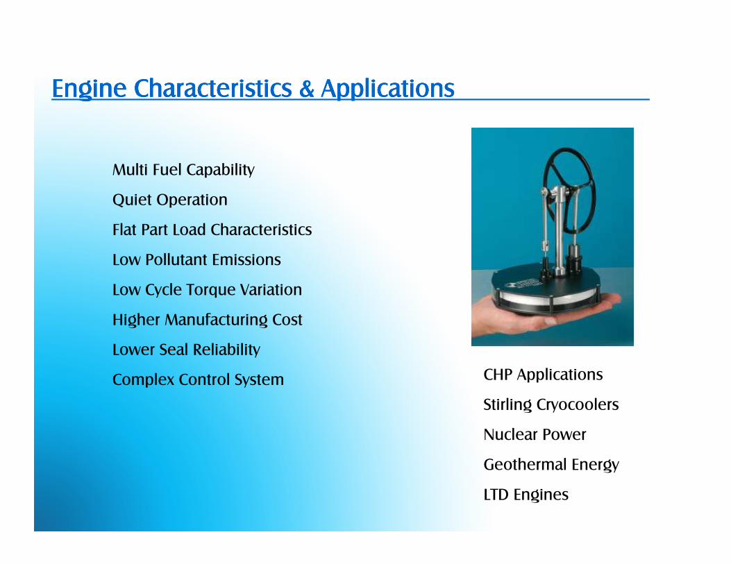
Engine Characteristics & ApplicationsEngine Characteristics & ApplicationsEngine Characteristics & ApplicationsEngine Characteristics & Applications
Multi Fuel Capability
Quiet Operation
Flat Part Load Characteristics
Low Pollutant Emissions
Low Cycle Torque Variation
Higher Manufacturing Cost
Lower Seal Reliability
Complex Control System CHP Applications
Stirling Cryocoolers
Nuclear Power
Geothermal Energy
LTD Engines

ClassificationClassificationClassificationClassification
� Alpha Type Alpha Type Alpha Type Alpha Type � Gamma TypeGamma TypeGamma TypeGamma Type� Beta TypeBeta TypeBeta TypeBeta Type
α configuration β configuration

Design CriteriaDesign CriteriaDesign CriteriaDesign Criteria
Design Working Temperatures: Design Working Temperatures: Design Working Temperatures: Design Working Temperatures: TTTTh h h h 150150150150ooooC TC TC TC Tcccc 25252525ooooCCCC
ηcarnotcarnotcarnotcarnot 30 %30 %30 %30 %
Design Heat Input:Design Heat Input:Design Heat Input:Design Heat Input: 200W200W200W200W Power Output (Indicated): 60WPower Output (Indicated): 60WPower Output (Indicated): 60WPower Output (Indicated): 60W
� Material LimitationsMaterial LimitationsMaterial LimitationsMaterial Limitations � Machining LimitationsMachining LimitationsMachining LimitationsMachining Limitations
� Inadequate Design Info.Inadequate Design Info.Inadequate Design Info.Inadequate Design Info. � Unavailability of Ready Made PartsUnavailability of Ready Made PartsUnavailability of Ready Made PartsUnavailability of Ready Made Parts

Initial ExperimentationInitial ExperimentationInitial ExperimentationInitial Experimentation
Experimentation VideoExperimentation VideoExperimentation VideoExperimentation Video

Alpha Type Stirling EngineAlpha Type Stirling EngineAlpha Type Stirling EngineAlpha Type Stirling Engine
1
2
3
4

Mathematical Modeling Mathematical Modeling Mathematical Modeling Mathematical Modeling
� First OrderFirst OrderFirst OrderFirst Order
� Second OrderSecond OrderSecond OrderSecond Order
� Third OrderThird OrderThird OrderThird Order
� IsothermalIsothermalIsothermalIsothermal
� AdiabaticAdiabaticAdiabaticAdiabatic

Ideal Gas Equation: PV = mRTIdeal Gas Equation: PV = mRTIdeal Gas Equation: PV = mRTIdeal Gas Equation: PV = mRT Working Fluid: airWorking Fluid: airWorking Fluid: airWorking Fluid: air
Initial Pressurization: noneInitial Pressurization: noneInitial Pressurization: noneInitial Pressurization: none Total System Mass: ConstantTotal System Mass: ConstantTotal System Mass: ConstantTotal System Mass: Constant
Piston Motion: sinusoidalPiston Motion: sinusoidalPiston Motion: sinusoidalPiston Motion: sinusoidal Regenerator Temp: TRegenerator Temp: TRegenerator Temp: TRegenerator Temp: Thhhh
Mathematical Modeling (contd.) Mathematical Modeling (contd.) Mathematical Modeling (contd.) Mathematical Modeling (contd.)
At t = 0:At t = 0:At t = 0:At t = 0: M = P (M = P (M = P (M = P (VVVVhhhh / T/ T/ T/ Thhhh + + + + VVVVtttt / / / / TTTTrrrr + + + + VVVVrrrr / / / / TTTTrrrr + + + + VVVVcccc / T/ T/ T/ Tcccc) / R) / R) / R) / R
System Pressure:System Pressure:System Pressure:System Pressure:P = MR / (P = MR / (P = MR / (P = MR / (VVVVhhhh / T/ T/ T/ Thhhh + + + + VVVVtttt / / / / TTTTrrrr + + + + VVVVrrrr / / / / TTTTrrrr + + + + VVVVcccc / T/ T/ T/ Tcccc))))

Computer SimulationComputer SimulationComputer SimulationComputer Simulation
� SIMULINK ModelSIMULINK ModelSIMULINK ModelSIMULINK Model
� Masked SystemMasked SystemMasked SystemMasked System
� Time DependencyTime DependencyTime DependencyTime Dependency
� Conversion of Conversion of Conversion of Conversion of θ to tto tto tto t

Computer Simulation (contd.)Computer Simulation (contd.)Computer Simulation (contd.)Computer Simulation (contd.)
� Basic User InterfaceBasic User InterfaceBasic User InterfaceBasic User Interface
� Dimensional VariablesDimensional VariablesDimensional VariablesDimensional Variables
� System InitializationSystem InitializationSystem InitializationSystem Initialization

Computer Simulation (contd.)Computer Simulation (contd.)Computer Simulation (contd.)Computer Simulation (contd.)

Fabrication StageFabrication StageFabrication StageFabrication Stage
Hot End:Hot End:Hot End:Hot End:
� Cylinder with inner grooveCylinder with inner grooveCylinder with inner grooveCylinder with inner groove
� Dead Volume for HeatingDead Volume for HeatingDead Volume for HeatingDead Volume for Heating
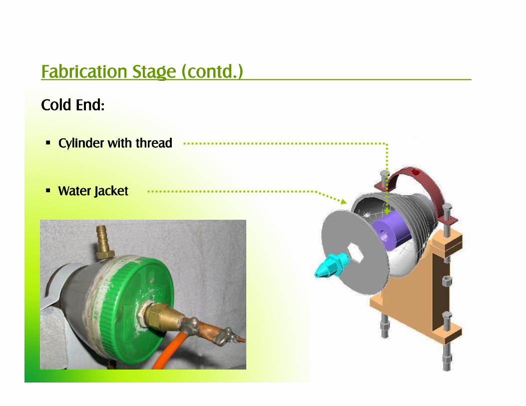
Fabrication Stage (contd.)Fabrication Stage (contd.)Fabrication Stage (contd.)Fabrication Stage (contd.)
Cold End:Cold End:Cold End:Cold End:
� Cylinder with threadCylinder with threadCylinder with threadCylinder with thread
� Water JacketWater JacketWater JacketWater Jacket

Fabrication Stage (contd.)Fabrication Stage (contd.)Fabrication Stage (contd.)Fabrication Stage (contd.)
Piston & Connecting Rod:Piston & Connecting Rod:Piston & Connecting Rod:Piston & Connecting Rod:

Fabrication Stage (contd.)Fabrication Stage (contd.)Fabrication Stage (contd.)Fabrication Stage (contd.)
Crank & Flywheel:Crank & Flywheel:Crank & Flywheel:Crank & Flywheel:
� Generates Sinusoidal Piston MotionGenerates Sinusoidal Piston MotionGenerates Sinusoidal Piston MotionGenerates Sinusoidal Piston Motion � 90909090oooo Phase AnglePhase AnglePhase AnglePhase Angle

Result AnalysisResult AnalysisResult AnalysisResult Analysis
Plot : variation of system pressure with time (crank angle) and hot end temperature
1.05
1.15
1.25
1.35
1.45
1.55
1.65
0 0.2 0.4 0.6 0.8 1 1.2 1.4 1.6 1.8 2
time (sec)
pre
ssu
re (
bar)
150 C 100 C 75 C

Result Analysis (contd.)Result Analysis (contd.)Result Analysis (contd.)Result Analysis (contd.)
Plot : variation of system pressure with time (crank angle) and cold end temperature
1.05
1.15
1.25
1.35
1.45
1.55
1.65
0 0.2 0.4 0.6 0.8 1 1.2 1.4 1.6 1.8 2
time (sec)
pre
ssu
re (
bar)
20 C 25 C 30 C

Result Analysis (contd.)Result Analysis (contd.)Result Analysis (contd.)Result Analysis (contd.)
Plot : hot end PV diagram @ different hot end temperatures
1.05
1.15
1.25
1.35
1.45
1.55
1.65
2.50E-05 3.00E-05 3.50E-05 4.00E-05 4.50E-05 5.00E-05 5.50E-05 6.00E-05 6.50E-05
volume (m3)
pre
ssu
re (
bar)
150 C 100 C 75 C
Plot : cold end PV diagram @ different hot end temperatures
1.05
1.15
1.25
1.35
1.45
1.55
1.65
5.00E-06 1.00E-05 1.50E-05 2.00E-05 2.50E-05
time (sec)
pre
ssu
re (
bar)
150 C 100 C 75 C
Hot End PHot End PHot End PHot End P----V DiagramV DiagramV DiagramV Diagram Cold End PCold End PCold End PCold End P----V DiagramV DiagramV DiagramV Diagram

Result Analysis (contd.)Result Analysis (contd.)Result Analysis (contd.)Result Analysis (contd.)
Plot 12.7: hot end PV diagram using fixed step solver
1.05
1.15
1.25
1.35
1.45
1.55
1.65
2.50E-05 3.00E-05 3.50E-05 4.00E-05 4.50E-05 5.00E-05 5.50E-05 6.00E-05 6.50E-05
volume (m3)
pre
ssu
re (
ba
r)
Plot 12.8: hot end PV diagram using variable step solver
1.05
1.15
1.25
1.35
1.45
1.55
1.65
2.50E-05 3.00E-05 3.50E-05 4.00E-05 4.50E-05 5.00E-05 5.50E-05 6.00E-05 6.50E-05
volume (m3)
pre
ssu
re (
ba
r)
Effect of SIMULINK Solver Effect of SIMULINK Solver Effect of SIMULINK Solver Effect of SIMULINK Solver ----
ODE3 Solver with Fixed StepODE3 Solver with Fixed StepODE3 Solver with Fixed StepODE3 Solver with Fixed Step ODE3 Solver with Variable StepODE3 Solver with Variable StepODE3 Solver with Variable StepODE3 Solver with Variable Step

Fundamental StudyFundamental StudyFundamental StudyFundamental Study
Incorporating PI and TIIncorporating PI and TIIncorporating PI and TIIncorporating PI and TI –
Pressure GaugePressure GaugePressure GaugePressure Gauge Thermocouple ReadThermocouple ReadThermocouple ReadThermocouple Read----OutOutOutOut

Case Case Case Case –––– 1:1:1:1: the hot piston is moved manually keeping the cold piston fixed
Case Case Case Case –––– 2:2:2:2: the cold piston is moved manually keeping the hot piston fixed
Plot : variation of system pressure with time (crank angle) without cold end motion
1
1.05
1.1
1.15
1.2
1.25
1.3
1.35
1.4
0 0.05 0.1 0.15 0.2 0.25 0.3 0.35 0.4 0.45 0.5
time (sec)
pre
ssu
re (
bar)
theoretical experimental
Plot 12.6: variation of system pressure with time (crank angle) without hot end motion
1
1.05
1.1
1.15
1.2
1.25
0 0.05 0.1 0.15 0.2 0.25 0.3 0.35 0.4 0.45 0.5
time (sec)
pre
ssu
re (
bar)
theoretical experimental
Case Case Case Case ---- 1111 Case Case Case Case ---- 2222
Fundamental StudyFundamental StudyFundamental StudyFundamental Study

ConclusionConclusionConclusionConclusion

RecommendationRecommendationRecommendationRecommendation
� Incorporation of Quick Heating Arrangement Incorporation of Quick Heating Arrangement Incorporation of Quick Heating Arrangement Incorporation of Quick Heating Arrangement
� Redesigning the Flywheel Redesigning the Flywheel Redesigning the Flywheel Redesigning the Flywheel
� Reduction in Dead Volume Reduction in Dead Volume Reduction in Dead Volume Reduction in Dead Volume
� Incorporation of a Regenerator Incorporation of a Regenerator Incorporation of a Regenerator Incorporation of a Regenerator
� Initial Pressurization Initial Pressurization Initial Pressurization Initial Pressurization
� Working Gas Working Gas Working Gas Working Gas

Thank YouThank YouThank YouThank You