design specification for pillpal medical...
TRANSCRIPT

Dr. Andrew Rawicz School of Engineering Science 8888 University Drive Simon Fraser University Burnaby, British Columbia V5A 1S6
Re: ENSC 440, Design Specification for a medical dispensary and reminder device
Dear Dr. Rawicz
The attached document is the Design Specification for the for the PillPal medical dispenser. The
following document highlights and justifies the implementation of all priority one functions listed in the
Functional Specification document. Our design targets the senior audience, who often are required to
adhere to complex medical regimens, and is primarily intended for a home environment. The goal is
have the PillPal become a common product in all homes and to be used by patients of all ages.
The Design Specification shall demonstrate the low level design of the PillPal medical dispenser. An in
depth analysis explains and justifies our choice in component selection and implementation techniques.
To thoroughly justify our design, the specifications are divided into hardware and software
implementation. The hardware section will explain the overall design and integration of each module
followed by an in depth analysis of each component. By doing so, the reasoning for each component is
defined and justified. Similarly, the Software section is explained thoroughly by breaking down the code
into different modules. Each module will explain and demonstrate the necessary functions required for
the PillPal to function as a coherent and safe medical dispenser.
Our diverse team of 4 senior computing and electronics engineers are dedicated to the development of
this device. Please feel free to contact us at [email protected] or [email protected] with questions or comments
regarding our enclosed documentation or our product.
Sincerely,
Izaak Lee CEO Capsule Corp

ii | P a g e
Design Specification for PillPal
Medical Dispenser
Izaak Lee;Charanpreet Parmar;Gurinder Dhaliwal;Clark Hsieh
March 14, 2013
Revision 1.0

iii | P a g e
In this day and age, it has become a common routine for many to take pills or tablets for various
reasons. Many will take pills to boost immune systems and some will require pills in a fight against
diseases. Whatever it may be, Capsule Corp is determined to create and design a product which will
adhere to various pill regimens. The design specifications of this document provides an in depth analysis
on the PillPal’s design. We first begin with a high level overview of the actual system. Then we will break
it down into its individual modules. The section after the individual modules discuss more detail about
each individual component and hardware chosen and their related design decisions.
The designs presented in this document focus mainly on completing the requirements to create a proof-
of-concept with core functionality as outlined as priority 1 in the functional specifications. As such, some
design concepts may be subject to change for the prototype and production models depending on
further testing and User Acceptance Tests.
To assist everyday medication consumers, the PillPal is designed to provide autonomous pill dispensing,
scheduling and notifying. The pill dispenser is a mechanical device with an intuitive GUI for users to
customize personalized schedules and remind settings. Thus, this document will highlight on the
following designs:
Hardware:
Label Reader: The mechanical mechanism which rotates pill bottles as a camera captures images.
The image is captured with a webcam through a Raspberry Pi which controls an Arduino
microcontroller.
Pill Allocator: The electrical DC motor that selects the correct container by rotating the pill
containers to store the pills. The motors are controlled via the Arduino microcontroller which
follows the commands provided by the Raspberry Pi.
Pill Dispenser: The linear motor is capable of picking up individual pills and dispensing them into
the correct bin given user inputs. The technique of picking up pills is done through a vacuum.
The Arduino is responsible for switching a relay to power the vacuum.
Software:
GUI: An interactive touch screen display allowing users to customize their scheduling and
emergency contacts. It also allows users to manually select settings such as WiFi, brightness, and
alarms.
Arduino: The microcontroller which governs the movement of all motors. It is also responsible
for reading inputs from sensors to ensure all items are aligned and medication is dispensed.
This document will further elaborate on the functional specifications and provides justification to our
method of choice.

iv | P a g e
Executive Summary ...................................................................................................................................... iii
Table of Contents ......................................................................................................................................... iv
Glossary of Terms........................................................................................................................................ vii
List of Figures ............................................................................................................................................... ix
List of Tables ................................................................................................................................................ xi
Equation List ................................................................................................................................................ xii
1 Introduction .......................................................................................................................................... 1
1.1 Scope ............................................................................................................................................. 1
1.2 Intended Audience ........................................................................................................................ 1
2 Hardware Overview .............................................................................................................................. 1
2.1 Pill Bottle Label Reader ................................................................................................................. 2
2.2 Pill Allocator .................................................................................................................................. 5
2.3 Pill Dispenser ................................................................................................................................. 9
2.4 Parts Description ......................................................................................................................... 10
2.4.1 Photomicrosensor (Transmissive) ....................................................................................... 10
2.4.2 TE - Relay (PB1660-ND) ....................................................................................................... 12
2.4.3 Shift Register (SN54HC595) ................................................................................................. 13
2.4.4 J-FET-Input Operational Amplifiers (TL082) ........................................................................ 14
2.4.5 Electrical Power supply ....................................................................................................... 17
2.4.6 Motor Power ....................................................................................................................... 17
2.4.7 Back EMF ............................................................................................................................. 18
2.4.8 Servo motor ........................................................................................................................ 18
2.4.9 Stepper Motor (42BYG011-25) ........................................................................................... 19
2.4.10 Stepper Motor Controller ................................................................................................... 21
2.4.11 Linear Motor ....................................................................................................................... 23
2.4.12 Camera ................................................................................................................................ 23
2.4.13 USB HUB .............................................................................................................................. 24
2.4.14 Touch Screen ....................................................................................................................... 24
2.4.15 Microcontroller ................................................................................................................... 25
2.4.16 Raspberry Pi ........................................................................................................................ 26

v | P a g e
2.4.17 Uninterruptible Power Supply ............................................................................................ 29
2.4.18 Finger Scanner ..................................................................................................................... 30
2.4.19 Gears ................................................................................................................................... 31
2.4.20 Plexi Glass (Poly (methyl methacrylate)) ............................................................................ 33
2.4.21 H-Bridge .............................................................................................................................. 34
2.4.22 Power Switch....................................................................................................................... 35
2.4.23 Speakers .............................................................................................................................. 36
3 Software .............................................................................................................................................. 36
3.1 General Software Requirements ................................................................................................ 36
3.2 Software Overview ...................................................................................................................... 37
3.3 Graphical User Interface ............................................................................................................. 38
3.3.1 Load Menu .......................................................................................................................... 40
3.3.2 Dispensing menu ................................................................................................................. 42
3.3.3 Calendar .............................................................................................................................. 42
3.3.4 Settings ................................................................................................................................ 43
3.4 Scheduler .................................................................................................................................... 45
3.5 Image Processing/OCR ................................................................................................................ 47
3.6 Data Storage ................................................................................................................................ 47
3.7 SMTP ........................................................................................................................................... 47
3.8 Arduino Software ........................................................................................................................ 48
3.8.1 ADC ...................................................................................................................................... 49
3.8.2 PWM.................................................................................................................................... 49
3.8.3 Interrupts ............................................................................................................................ 50
3.8.4 UART .................................................................................................................................... 51
3.8.5 Servo ................................................................................................................................... 52
3.8.6 Shift Register ....................................................................................................................... 52
3.8.7 General IO Pins .................................................................................................................... 52
3.8.8 Stepper Motor Driver .......................................................................................................... 53
3.8.9 H-Bridge .............................................................................................................................. 53
3.8.10 Arduino Coding ................................................................................................................... 56
4 Test Plan .............................................................................................................................................. 66
4.1 GUI Unit Testing .......................................................................................................................... 66
vi | P a g e
4.1.1 Navigation Testing .............................................................................................................. 66
4.1.2 Home Menu Testing ............................................................................................................ 66
4.1.3 Pill Loading Testing .............................................................................................................. 66
4.1.4 Pill Dispensing Testing ......................................................................................................... 67
4.1.5 Calendar Testing ................................................................................................................. 67
4.1.6 WiFi Settings Testing ........................................................................................................... 67
4.1.7 Brightness Settings Testing ................................................................................................. 68
4.1.8 Alarms Settings Testing ....................................................................................................... 68
4.1.9 Outside Alerts Settings Testing ........................................................................................... 69
4.1.10 User Settings Testing ........................................................................................................... 69
4.1.11 Alarm System Testing .......................................................................................................... 70
4.1.12 Outside Alerts System Testing ............................................................................................ 70
4.2 VAM module ............................................................................................................................... 70
4.2.1 Suction test ......................................................................................................................... 70
4.2.2 Pill Container Seeking Test .................................................................................................. 71
4.2.3 Pill Container Selection Test ............................................................................................... 71
4.2.4 VAM Sliding Test ................................................................................................................. 71
4.3 Label Reader ............................................................................................................................... 72
4.3.1 Pill bottle Rotation .............................................................................................................. 72
4.3.2 Picture taking ability ........................................................................................................... 72
4.4 Pill Dispenser ............................................................................................................................... 73
4.4.1 Pill Count Test ..................................................................................................................... 73
4.4.2 Dispenser Cup Test: ............................................................................................................ 73
5 Finances .............................................................................................................................................. 74
6 Conclusion ........................................................................................................................................... 75
7 References .......................................................................................................................................... 75
8 Appendix – Hardware Test Checklist .................................................................................................. 78
9 Appendix – Software Test Checklist .................................................................................................... 81

vii | P a g e
ADC - Analog to Digital Converter ARM -Acorn RISC Machine (Now referred to as ARM) ATX - Advanced Technology eXtended BJT - Bipolar Junction Transistor C-MOS - Complementary Metal Oxide Semiconductor DC - Direct Current DIP - Dual Inline Package DSP - Digital Signal Processing EEPROM - Electrically Erasable Programmable Read-Only Memory EMF - Electro-Magnetic Field FET - Field effect Transistor FPS - Frames Per Second GPU - Graphic Processing Unit GUI - Graphic User Interface HD - High Definition HDMI - High Definition Multimedia Interface HP - Hewlett Packard I/O - Input/Output IC - Integrated Circuit J-FET - Junction gate Field Effect Transistor JPEG - Joint Photographic Experts Group LCD - Liquid Crystal Display LED - Light Emitted Diode LED - Light Emitting Diode Li-ion - Lithium ion LK (register clock), and the SER LVDS - Low-voltage differential signaling MCU - Microcontroller Unit MP - Megapixels NC - Normally Closed NO - Normally Open OC - outer diameter of gear bore if flanged OCR - Optical Character Recognition OD - Outer diameter of the whole gear Op-Amp - Operational Amplifier PC - Personal Computer PD - Pitch diameter of the gear PWM - Pulse Width Modulation RAM - Random Access Memory RGB - Red, Green, Blue RISC - Reduced Instruction set Computing SATA - Serial ATA SMTP - Simple Mail Transfer Protocol SoC - System on Chip SPC - Smart pill container

viii | P a g e
SPI - Serial Peripheral Interface SRAM - Static Random-Access Memory SRCLK - Shift Register clock SSID - Service Set Identifier TCP - Transmission Control Protocol TFT - Thin Film Transistor TTL - Transistor Transistor Logic UCV - USB Video Class UK - United Kingdom UPS - Uninterruptable Power Supply USART - Universal Synchronous/Asynchronous Receiver/ Transmitter USB - Universal Serial Bus V4L - Video4Linux VAM - Vacuum Arm Manipulator VDC - Direct Current Voltage WiFi - Wireless Fidelity (802.11 IEEE standard) XML - Extensible Markup Language

ix | P a g e
Figure 1 - Orthographic view of label reader design and camera placement .............................................. 3
Figure 2 - Orthographic view of label reader pill bottle rotating mechanism .............................................. 4
Figure 3 - Label reader pill roller gearing ...................................................................................................... 5
Figure 4 - Top view and side view of the Smart Pill Container (SPC) ............................................................ 6
Figure 5 - Servo to main shaft of SPC gearing ............................................................................................... 7
Figure 6 - The vacuum arm manipulator (VAM) and photomicrosensor alignment to SPC ......................... 8
Figure 7 - Pill Dispenser cross section view ................................................................................................ 10
Figure 8 – Cross sectional view of the photomicroscensor from Digikey ................................................... 11
Figure 9 – Internal Circuit diagram of the photomicrosensor .................................................................... 12
Figure 10 – Phyiscal construction of the photomicrosensor ...................................................................... 12
Figure 11 – Orthogal view of the 10A relay ................................................................................................ 13
Figure 12 – High level overview of relay design to power motor (10Ω symbol) ........................................ 13
Figure 13 – Pin layout of the SN54HC595 Shift Register Chip. ................................................................... 14
Figure 14 - DIP Shift Register Chip .............................................................................................................. 14
Figure 15 - Schmitt trigger design for pill detection ................................................................................... 15
Figure 16- Non-inverting Op-amp design for Speakers .............................................................................. 16
Figure 17 – Pin layout of J-FET op-amp [6] ................................................................................................. 16
Figure 18 – Input pin information regarding current biasing and current offset of J-FET .......................... 16
Figure 19 – input current biasing and current offset of the TL0741 op-amp ............................................. 17
Figure 20 – General brushed motor design [9] ........................................................................................... 18
Figure 21 – View of Sparkfun Stepper motor ............................................................................................. 20
Figure 22 – Step by step explaination of how stepper motor control works ............................................. 21
Figure 23 – Stepper motor driver ............................................................................................................... 22
Figure 24 – Pin layout and operation data of the Stepper motor Controller ............................................. 22
Figure 25 - Front view of HP3110 Camera .................................................................................................. 23
Figure 26 – D-Link USB Hub for USB communication and power ............................................................... 24
Figure 27 - Raspberry Capacitive Touch screen .......................................................................................... 25
Figure 28 – Arduino Uno module device .................................................................................................... 26
Figure 29 - Raspberry Pi Module ................................................................................................................. 27
Figure 30 - Raspberry Pi Model B, peripheral layout .................................................................................. 28
Figure 31 - Uninterruptable Power Supply (not implemented in prototype) ............................................. 30
Figure 32 – Demonstration of the Finger Print reader ............................................................................... 31
Figure 33 – Measurement of typical gears used in the PillPal [22] ............................................................ 32
Figure 34 – Demonstration of outter diameter and pitch diameter .......................................................... 32
Figure 35 – The chemical bond of Plexi Glass [23] ...................................................................................... 33
Figure 36 – Example Sheet of Plexi Glass [25] ............................................................................................ 34
Figure 37 - Example H-Bridge Circuit .......................................................................................................... 35
Figure 38 – Image of the on off module ..................................................................................................... 36
Figure 39 - Qt feature overview .................................................................................................................. 38
x | P a g e
Figure 40 - Qt keyboard design ................................................................................................................... 39
Figure 41 - The PillPal home screen ............................................................................................................ 40
Figure 42 - Pill loading flow chart ............................................................................................................... 41
Figure 43 - PillPal calendar page ................................................................................................................. 42
Figure 44 - User setting flow chart .............................................................................................................. 44
Figure 45 – Scheduler flow chart ................................................................................................................ 46
Figure 46 - Arduino Uno Pin Overview........................................................................................................ 49
Figure 47 - Pill Detector .............................................................................................................................. 50
Figure 48 - Dispensing Cup and Photomicrosensor .................................................................................... 53
Figure 49 - Wiring Diagram Overview for Arduino ..................................................................................... 55
Figure 50 - Schematic Diagram Overview for Arduino ............................................................................... 56
Figure 51 - Arduino Boot up flow chart ...................................................................................................... 60
Figure 52 - Arduino Main Loop flow chart .................................................................................................. 61
Figure 53 - Arduino Finger Print Reader flow chart .................................................................................... 62
Figure 54 - Arduino Label reader flow chart ............................................................................................... 63
Figure 55 - Arduino Smart Pill Container flow chart ................................................................................... 64
Figure 56 - Arduino Vacuum Arm Manipulator flow chart ......................................................................... 65

xi | P a g e
Table 1 - Photomicrosensor truth table ........................................................................................................ 8
Table 2 - Power supply output pins ............................................................................................................ 17
Table 3 - Priority list of component during power outage ......................................................................... 29
Table 4 - Advantage and Disadvantage table for Qt Platform .................................................................... 37
Table 5 - Truth table for H-Bridge ............................................................................................................... 54
Table 6 - UART Framing bits ........................................................................................................................ 57
Table 7 – Commands to be decoded for Arduino ....................................................................................... 58
Table 8 - Financial Summary ....................................................................................................................... 74

xii | P a g e
Equation 1 ................................................................................................................................................... 18
Equation 2 ................................................................................................................................................... 18
Equation 3 ................................................................................................................................................... 19
Equation 4 ................................................................................................................................................... 19
Equation 5 ................................................................................................................................................... 19
Equation 6 ................................................................................................................................................... 19
Equation 7 ................................................................................................................................................... 19
Equation 8 ................................................................................................................................................... 30

Design Specification for PillPal Medical Dispenser Introduction
1 | P a g e
The PillPal is a pill dispensing machine capable of generating schedules for multiple patients, dispense
drugs automatically, and have multiple techniques to remind users that it is time for their medication.
By using this product, patients are now reminded periodically by the machine through the technology
available around them. Reminders such as emails, online calendars, text messages, and phone calls are
available through this product. Of course, the simple alarm is still available. The design of the PillPal is
divided into the hardware and software sections, this document is written to justify our design choices.
Based on the functional specification document, this design specification highlights and details the
implementation of functions related to the PillPal. The information provided will justify the design
techniques implemented and will further provide detailed information regarding mechanical parts and
software interface. It should be noted that the design specification will not fulfill all functions
highlighted in the functional specification document.
The design specification document is created to guide and provide detailed information for Capsule Corp
engineers. This document will detail all components and modules to demonstrate how each feature is
implemented.
The document will also highlight the features on each component to further justify our component
choices.
This section shall provide the list of components used and highlight all relevant technical details about
each component. Breaking the hardware into modular sections we can describe the project as
1. Label Reader
2. Pill Allocator
3. Pill Dispenser
These individual modules above together work in unity to deliver medications to patients in a safe and
timely manner. The goal of the PillPal is to be a device that is as simple and intuitive as possible while
performing all the necessary actions flawlessly. As such, the label reader is designed to automatically
read and record the medical labels on pill bottles. Utilizing a 12V, 2 phase stepper motor to rotate the
pill bottle and a 5.7 megapixel HP camera to capture images the label reader is capable of producing a
flat image from a curved surface. The images are stitched together using our own personal code. Once

Design Specification for PillPal Medical Dispenser Hardware Overview
2 | P a g e
stitched, PillPal will create a schedule based on the image created. Using optical character recognition
(OCR) technology, we can determine and pinpoint key words which will create a schedule for our
patients. To do the image processing and scheduling a Raspberry Pi computer is used. The Raspberry Pi
is a credit card size computer using an ARM processor. Released last year in the UK, the Raspberry Pi is a
low cost, powerful computer. Complete with audio and full 1080p HD video outputs, the Raspberry Pi is
the heart of our device.
Connected to the Raspberry Pi is a touch screen for user interaction. The stitched image is displayed on
a 10.1” touch screen. The Raspberry Pi interfaces with the touch screen using a special connector for the
Raspberry Pi designed by Chalk Electronics. The touch screen is connected through the LVDS cable into
the LVDS-HDMI assembled converter which outputs HDMI and USB into the Raspberry Pi. The specially
designed assembly kit allows us to install the device through plug-n-play method, treating touching the
screen as mouse clicks, thus no driver development is required. The screen prompts users to make
changes or customize the generated medication schedule. Once the schedule and medications are
confirmed, the pills are automatically stored into a designated container designed by Capsule Corps. A
total of 8 different pills may be stored in the PillPal, each container sits on an angle to ensure all
medications are able to be picked up by the VAM. The size of each container is designed to fit the largest
over the counter pill containers available. From research, Capsule Corp understands that largest pill
bottles reach up to 60 Drams. [1] The overall system is rotated by a servo motor capable of producing
13kg/cm of torque. The Metal Gear Digital Servo Motor will provide the power and precision required to
ensure the correct pills are delivered. To further ensure the correct pills are taken, photomicrosensors
are placed to detect container numbers. A series of 4 sensors are used to provide a binary code to the
Arduino Uno. The pills are stored until a patient requires the medication.
Once the patients acquire pills, he or she must verify his or her identity using the fingerprint reader. The
servo then rotates the designated container to the VAM (Vacuum Arm Manipulator) and the pills are
picked out individually by using a DC vacuum. The vacuum arm is operated by a linear motor. The motor
moves a hose in a linear motion, picking up pills in the container as it enters. Once retracted, the pill is
dropped into the dispensing mechanism. The dispensing mechanism is used to ensure that the correct
number of pills are dispensed to prevent overdosing and underdosing. The switch for the dispensing
mechanism is another simple servo motor which toggles to release the pill. The PillPal is designed to
have redundant checks and reminders to ensure the pills are delivered to the correct patients in the
most efficient manners.
To further highlight the PillPal design, in depth examination of each module followed by specifications of
hardware components are listed below.
This section will outline our design choices for the pill bottle reader and will reference sections in this
documentation for more detailed look into the components we have chosen. Figure 1 is a CAD drawing
of the label reader highlighting the placement of the camera and the dimension of the enclosure.

Design Specification for PillPal Medical Dispenser Hardware Overview
3 | P a g e
Figure 1 - Orthographic view of label reader design and camera placement
The main function of the bottle label reader is to automate the process of which to read the data from
the prescriptions labels themselves. The pill bottle reader is made up of rollers, a motor, gears, and the
physical compartment to hold everything together. Figure 2 provides an orthographic view of the bottle
rolling module. To rotate the pill bottles, a stepper motor and gears are used.
Webcam
Front
Top

Design Specification for PillPal Medical Dispenser Hardware Overview
4 | P a g e
Figure 2 - Orthographic view of label reader pill bottle rotating mechanism
We chose the particular gear ratio with consideration to three constraints.
1) availability and pricing
2) Physical dimensions of the compartment of which it will be placed
3) relative size between the different gears
Due to the physical constraints of our label reader’s compartment’s design, 4-8 centimeter of space is
available to place our gears. We chose to transfer motion via an intermediary gear because of the size
constraint of the motor itself and the ability to support a bigger diameter gear based on the dimensions
of the enclosure. We chose the simple design of the spur gear type due to the simplicity and the
abundant availability of it. For compactness, other designs for gear configuration can be considered to
minimize the physical footprint, increase rigidity, and precision.
Geared Roller
Gear Box
Stepper Motor Front
Top

Design Specification for PillPal Medical Dispenser Hardware Overview
5 | P a g e
The rollers are placed 20 mm (0.787402 inches) apart to allow enough room for the camera to capture
images but enough to hold the pill bottles back and allow for rotation. Standard pill bottles and vials
range from 0.875 inch to 1.8125 inch diameter.
The camera placement is 4 cm below the location of the pill bottle. This location gives us flexibility for
adjustable focus as well as sufficient distance for lighting to avoid blooming in our pictures. We will be
controlling the motors and with the Arduino Uno and the camera with the Raspberry Pi. For quick
prototyping purposes, items will be bread boarded first before spending vast amount of time working
and cost with custom designed boards with our microcontrollers. Figure 3 demonstrates the gearing to
be used in the proof of concept design.
Figure 3 - Label reader pill roller gearing
The pill allocator contains two modules, one is the dispensing arm, we call, and VAM (vacuum arm
manipulator) and the other are the storage compartments called the SPC (smart pill container).

Design Specification for PillPal Medical Dispenser Hardware Overview
6 | P a g e
Figure 4 - Top view and side view of the Smart Pill Container (SPC)
The SPC compartments are built from plastic tubes measuring 6cm in height with a diameter of 6cm.
These containers are situated on a dome shaped elevation; this designed angle is 30 degrees and is
implemented such that the pills will always fall to the lower portion of the SPC. This ensures that pills
are not stuck and that the VAM is able to pick pills from the same location every time. Beneath the
dome is a 3 ⅙” metal rod connected to the servo motor through a couple of gears. The gears are chosen
to allow the servo motor to deliver maximum torque and precision to the SPC. The ratio from the end
effect is small due to the low ratio between gears from the servo motor to the metal shaft. Because of
the gears, the motor is displaced 26mm away from the metal shaft.
Servo Motor Gear Box
Shaft

Design Specification for PillPal Medical Dispenser Hardware Overview
7 | P a g e
Figure 5 - Servo to main shaft of SPC gearing
To determine the position of each pill container, each container is fitted with sensor tripping wires to
trip 4 photomicrosensor. By placing specific number of wires, a binary code is used to determine which
container is in line with the VAM.

Design Specification for PillPal Medical Dispenser Hardware Overview
8 | P a g e
Figure 6 - The vacuum arm manipulator (VAM) and photomicrosensor alignment to SPC
Table 1 - Photomicrosensor truth table
Sensor Not Lined Up 1 2 3 4 5 6 7 8
s(0) 0 0 0 0 0 0 0 0 1
s(1) 0 0 0 0 1 1 1 1 0
s(2) 0 0 1 1 0 0 1 1 0
s(3) 0 1 0 1 0 1 0 1 0
Through this method of feedback, the Arduino is capable of determining the position of the SPC at all
time. An alternative to this is to use short range infrared sensors paired with a barcode of sort. However,
Vacuum Tube
Vacuum
Photomicrosensor
Linearized Motor

Design Specification for PillPal Medical Dispenser Hardware Overview
9 | P a g e
we felt this method, although not as compact and elegant as using the infrared sensors, would be easier
to construct and debug since the barcode reader requires some external circuitry to be built whereas
the photomicrosensors are designed to work out of the box. Another solution was to simply use a
stepper motor and a few gears to track the SPC, but this could cause drastic errors due to the motor
slipping or not turning as far as thought. Therefore, we chose to use the photomicrosensors due to its
ease of use and repeatability factors.
To pick up the pills, the prototype PillPal utilizes a DC motor to generate vacuum to lift up the pills. The
DC motor is a 7.6V, 7 amp generator placed at the bottom of the PillPal. We managed to find an
appropriate vacuum by taking apart and slightly modifying a handheld vacuum intended for cleaning.
Although there are standalone vacuum solutions available, we found that they tended to be far more
costly than we intended for a proof of concept of the PillPal. In our final product design we chose a
powerful specialized vacuum made by Thompson, a renowned vacuum/ compressor pump maker. It has
an AC motor, capable of more power, and can produce a flow rate maximum 13 LPM (liters per minute)
to a lower 3.8 LPM when sustaining maximum vacuum pressure.
A rubberized hose is attached to the connected to the vacuum and fastened to a linear motor placed 5
cm above the SPC. The linear motor moves the hose in and out of the SPC to pick up pills. Running off
12VDC rails, the linear motor travels at 200mm/sec, delivering pills at a quick pace.
The two main contributing factors to the ability of the vacuum to pick up an object is the force
generated by the difference and of pressure created by the vacuum, and the air flow rate at which the
vacuum displaces air. From trial and error with various vacuums, we successfully managed to roughly
spec out a viable vacuum solution.
The Pill Dispenser is where the pills fall and are finally dispensed for the patients. This crucial module is
the last line of defense to ensure the correct patient is taking the correct drugs. When the VAM picks up
the pill, it is dropped into a funnel and into a tunnel where a laser checks to make sure a pill is picked up
and only a single pill is dropped into this compartment. A 5mW laser diode [2] is used in conjunction
with a photodiode that is placed at the bottom of the funnel. This ensures that the pill will pass through
it no matter the angle the pill has been dropped and it can be counted correctly.

Design Specification for PillPal Medical Dispenser Hardware Overview
10 | P a g e
Figure 7 - Pill Dispenser cross section view
When the pill lands on the switch plate, the Arduino will wait until it is sure no more pills will drop. It will
then compare the number of pills expected versus the actual detected before finally dispensing. A final
check put in place is to check if the dispensing cup is waiting for the medication to be dispensed using a
fifth photomicrosensor. Once everything is confirmed, the switch plate rotates and drops the drug into a
dispense cup. When the cup is removed the sensor will send information to the Arduino informing the
Raspberry Pi the cup is missing and we assume the user has consumed the pills. However, if the user
does not confirm within a set time, the switch plate will dispense the pills in a side bin for storage. This
bin is used to hold pill that are not consumed or missed to avoid double doses for patients.
Model: EE-SX3070
Pill Selector

Design Specification for PillPal Medical Dispenser Hardware Overview
11 | P a g e
This electronics device is a sensor that we used to detect the position of the pill containers. The
photomicrosensor uses a LED to send continuous light waves to a receiver with built in amplifier. By
connecting to C-MOS and TTL (transistor-Transistor Logic) devices a high or low trigger can be created
for detection. Because the LED is always turned on, the photomicrosensors have a built in temperature
compensation circuit. The common uses of this device are for the detection of passing objects or for
positioning applications. Another physical component called the “” dog”” will pass through between the
photomicrosensor and be optically detected and produce an electrical signal. The physical dimensions
are shown below in Figure 8. [3]
Figure 8 – Cross sectional view of the photomicroscensor from Digikey
We chose this device for its flexible voltage operations at 4.5 all the way to 16 volts. We will be
operating this electrical device at 5V for convenience and low current consumption of 1.7 mA. These
devices are relatively low price and are very practical for our application for the degree of accuracy and
reliability in our product. This device is also contactless, thus will not fail due to mechanical failure or
other wear and tear.
The sensor receives an analog input and produces a digital output through a Schmitt trigger which is
built in the enclosure. Figure 9 provides the internal circuit of the photomicrosensor while Figure 10
shows the structure of the sensor.

Design Specification for PillPal Medical Dispenser Hardware Overview
12 | P a g e
Figure 9 – Internal Circuit diagram of the photomicrosensor
Figure 10 – Phyiscal construction of the photomicrosensor
The relay is a standardized single pole single throw power device. It has two terminals that that will
close a contact to drive high current devices with the establishment of a magnetic field with the usage of
some current. It is capable of handling 30VDC and 10A. This device cannot be directly connected to a C-
MOS output device as it requires at least 70mA, which normal I/O pins are unable to support. The other
“output” terminals on the relay are labeled NO (normally open) or NC (normally closed), denoting the
standard state of those pins when no current flows. Shown below are the mechanical dimensions of the
relay device.

Design Specification for PillPal Medical Dispenser Hardware Overview
13 | P a g e
Figure 11 – Orthogal view of the 10A relay
In our design we are utilizing the relay to drive higher power devices with the help of a standard BJT
configured as a simple switch. The diode seen in the configuration is acting as a flyback device, so when
the relay is switched off the current from the collapsing magnetic field of a motor or inductive load can
have a path to flow and dissipate.
Figure 12 – High level overview of relay design to power motor (10Ω symbol)
The shift register is a device that uses a cascade of flip flops and can take in serial data and provide
parallel outputs (SIPO). The SN54HC595 shift register is an 8bit storage register requiring a minimum of

Design Specification for PillPal Medical Dispenser Hardware Overview
14 | P a g e
3 control pins in order to assert 8 output pins. Commonly, a shift register is used to expand the number
of pins for a micro controller while utilizing only a little bit of head room. [4] The chip itself allow 2 more
pins for master clear, to clear data in all the registers, as well as a output enable, which places the
output pins either in a high output impedance state or asserts the stored data bits. The chip is able to
achieve a fast speed with only 13 nanoseconds in the propagation delay of each serial data clocking
speed. The chip also requires only 5V operation voltage, which we readily have available for and the
input current draw is exceptionally low at only 1 microamp.
Figure 13 – Pin layout of the SN54HC595 Shift Register Chip.
We chose this chip, the DIP16, (dual inline package) for its abundance availability in the electronics
community and its well-balanced set of functional specifications. This chip will be used as output control
for the Arduino to control the included devices in the PillPal.
Figure 14 - DIP Shift Register Chip
The J-FET (junction field effect transistors) operational amplifiers are used in a few locations throughout
the device. The operational amplifier is used in the circuit for the photo-diode in our laser module to

Design Specification for PillPal Medical Dispenser Hardware Overview
15 | P a g e
detect the acquisition of the pill. Also, the op-amps are used in a Schmitt trigger design to set threshold
levels for the photo-diode output. Figure 15 demonstrates the use of op-amps in a Schmitt trigger
design. [5]
Figure 15 - Schmitt trigger design for pill detection
Lastly, the op-amps will be used in a simple voltage amplifier for our speakers. Figure 16 highlights our
voltage amplifier design.

Design Specification for PillPal Medical Dispenser Hardware Overview
16 | P a g e
Figure 16- Non-inverting Op-amp design for Speakers
The output of this signal will be fed to the Arduino. We chose J-Fets in our design is due to the lower
input current draw, in pico-amps instead of nano-amps.
Figure 17 – Pin layout of J-FET op-amp [6]
Figure 18 – Input pin information regarding current biasing and current offset of J-FET

Design Specification for PillPal Medical Dispenser Hardware Overview
17 | P a g e
Figure 19 – input current biasing and current offset of the TL0741 op-amp
The TL082A comes in a variety of packaging, but the one chosen is the 8 pin DIP (dual inline package).
There are many operational amplifiers to choose from, this specific amplifier was chosen for the very
high input impedance and very high slew rate of 13 V/us. The J-FET op-amp also have a wide common/
differential mode operating Voltage range when compared to a standard operational amplifier 741
which was designed in the 70’s.
To provide power to all the electrical components, a Dell power supply is use to supply power. The Dell
NPS-275BB B is a 275W power supply with single ATX, P4 and SATA connector. The ATX connector is a 24
pin connect producing three main output, +3.3VDC, +5VDC, and +12VDC. A table below summarizes all
the outputs and maximum current draw per each pin.
Table 2 - Power supply output pins
Output +5VFP -12V +12V +5V +3.3V
Max Load 1A 0.5A 12A 17A 3A
The $45.00 power supply provides chosen contains a high range of output voltages and allows for high
current draw. This is optimal for our motors and Raspberry Pi computer as they all run on 5 V or 12 V
rails.
The design of PillPal requires a total of 35 motors. Each motor is designated to complete a single task.
There are 3 types of different motors in total, 1 stepper motor, 2 servo motors and 2 normal DC motors.
The basic difference between stepper and servo motors is the physical characteristics of the motor and
how it is controlled. Typically stepper motors is wounded in such a way that the motors create steps.
These steps are created using magnetic fields. [7] The number of steps present allows for higher
precision. These steps allow the motor to know the exact position at all times, compared to a servo
motor, a servo motor utilizes an internal or external encoder to determine where the motor is positions.
Because a servo motor does not use steps, it is able to produce much more torque and speed. [8] One of
the DC motors is used for the linear motor, using a belt to create linear movement from the motors
rotation. The other DC is used to create the vacuum by simply rotating very fast. The three different
motors are selected to perform specific task catered to the strengths of the motors.

Design Specification for PillPal Medical Dispenser Hardware Overview
18 | P a g e
Figure 20 – General brushed motor design [9]
Back EMF (electromotive force) is the voltage generated or the electromagnetic force generated by a
spinning motor that is established in the opposite direction of the input voltage. This is due to Lenz’s law
of electromagnetism thus the magnetic field generated is directly related to the voltage and the number
of turns of wire in the armature. The generated back EMF will oppose the input voltage thus defining the
final max rotational speed of the motor itself.
The servo motor simply rotates the pill holders so that pills can be reached by other modules. Our servo
motor is purchased for the amount of torque it is capable of producing on 7.2VDC. At 7.2VDC the motor
is able to produce 13kg cm of torque. Using Equation 1 we are able to find the force required to move
our SPC. [10]
Equation 1
Where is the torque and where is the single point vector relative to the fulcrum, and F is the force
acting on the single point. We can calculate the force required to move the pill holder when it is at
maximum capacity. By utilizing the cross products definition, we can change Equation 1 to Equation 2
Equation 2
where is 90, thus the equation is further reduced to Equation 3.

Design Specification for PillPal Medical Dispenser Hardware Overview
19 | P a g e
Equation 3
given the torque from the datasheet and the radius of our arm, the required force to move our pill
container is determined to be roughly 1 N.
Most servos are only capable of rotating 180 degrees, thus 2 servos are typically required to reach full
360 degree rotation. Unlike most servo motors, the Metal Gear Digital Servo is able to rotate 360
degrees. Because of this feature, a single servo is sufficient. However, with 2 servos the speed can
significantly increase but the price follows. With the Metal Gear servo, a maximum 0.84sec / 360
degrees is obtained. This speed shall swiftly provide pills to medical patients.
The stepper motor is a precision motor which is accurate to +- 0.1 degree per 360 degrees rotation. We
chose the stepper motor for the precision required to take accurate picture with the label reader. This
step is crucial in obtaining perfect images. To do so, we use a stepper motor purchased at Sparkfun
Electronics. The motor has a stepping angle of 1.8 degrees and is powered using 12VDC. The current
rating is 0.33A. [11] The fully loaded pills bottles do not carry a significant load and the 2.3kg cm torque
is more than sufficient to rotate a bottle on its side.
Assuming the pill bottle weighs , radius and stepper has holding torque of .23NM the formula for Torque of a cylinder is stated in Equation 4
Equation 4
Where is the moment of inertia, which is represented as
Equation 5
And is the angular acceleration
Equation 6
Substituting Equation 5 and Equation 6 into Equation 4, torque is now redefined as Equation 7
Equation 7
Inserting our know values, under the assumption that the speed it goes at is
, we get

Design Specification for PillPal Medical Dispenser Hardware Overview
20 | P a g e
( )( )( )
so according to the math we have more than enough torque from our stepper to rotate a pill bottle as
expected from such a light bottle.
Figure 21 – View of Sparkfun Stepper motor

Design Specification for PillPal Medical Dispenser Hardware Overview
21 | P a g e
Figure 22 – Step by step explaination of how stepper motor control works
Since the stepper motor is designed for two pole, four pin layout, we chose the EasyDriver Stepper
Motor Driver from Sparkfun to driven our motor. This stepper motor driver uses the A3967SLB chip
made by Allegro, which is capable of driving a device at 30V +- 750 mA. The driver chip can operates at a
3.0V to 5.5V logic level and has thermal shutdown capability for safety reasons. It has a built in H- bridge
which is regulated by PWM (pulse width modulation) and is designed to work at a variety of step sizes:
full, half, quarter, and eight-step mode. These fine adjustments give up better control over the actual
mechanical movements of our device. [12]

Design Specification for PillPal Medical Dispenser Hardware Overview
22 | P a g e
Figure 23 – Stepper motor driver
Figure 24 – Pin layout and operation data of the Stepper motor Controller
As we can see from the data sheet provided by the driver chip, the voltage supplied, the current
capabilities, and the degree of accuracy is more than sufficient for our purpose on the label reader to
operate the mechanisms to rotate the pill bottles. We chose this product due to its popularity, as it is
currently the version 4.4 which means most bugs and issues are ironed out and performance maximized.
The support for this driver chip is very broad as it is one of the more commonly used driver chip by
Arduino users and designers.

Design Specification for PillPal Medical Dispenser Hardware Overview
23 | P a g e
The linear motor is used to control our vacuum tube. The tube will reach into the pill containers via
linear motion and pick pills up. As mentioned above, the linear motor module is actually a standard
brush motor that drives a belt causing a trolley to move in a linear motion. Unlike, the stepper motor or
our servo motor, there is no mechanical or electrical encoder to tell the motor where the position of the
trolley is located. Instead, a linear potentiometer is placed and a reading must be taken in order for the
Uno to know where the trolley is currently located. There is a single 1k ohm potentiometer and 4 viable
pins to read from, by continuously reading the center tap voltage of a constant known voltage across
the potentiometer when the motor is in motion, we can determine the location of the linear motor
effector and control it as necessary.
As mentioned above, the motor offers very low torque but is able to travel at 200mm/sec. [13] Since the
motor is not carrying much weight, a high torque motor is not required.
The label reader utilizes the camera to take multiple images of the circular pill bottle. By taking multiple
images, the Raspberry Pi will stitch the images creating a flat image. Utilizing the HP camera 3110’s
720p, and 5.7 Megapixel still picture resolutions, the images are taken with extreme clarity. The camera
also supports autofocus feature which assists in the image clarity. The camera cost $11.99 retail and
provides us with excess features including 30 FPS video resolution.
Figure 25 - Front view of HP3110 Camera
The HP camera is powered through USB 2.0, and sends data via the same cable. The data is compressed
via the built in JPEG and YUY image encoder located inside the camera housing. For this reason, the JPEG
images require decompression before it may be processed further using standard RGB (Red, Green,
Blue) pixel values. [14]

Design Specification for PillPal Medical Dispenser Hardware Overview
24 | P a g e
The camera is also chosen because it is UCV compliant and is able to communicate to the Raspberry Pi
via V4L (Video4Linux) without any additional drivers. Using V4L, we are able to adjust the focus settings,
which is critical for taking clear macro shots of the pill bottle’s label. The main reason for choosing this
device is for its low retail price and wide range of functions.
The PillPal utilizes many USB powered devices. The Raspberry Pi only has two lower power output USB
ports, thus a USB hub was purchased to power our many USB powered devices. The D-Link H7BL 7 Port
USB 2.0 Hub contains 7 downstream USB 2.0 ports along with a single upstream port. Currently, the USB
hub is used to power the Raspberry Pi, Arduino Uno microcontroller, the USB touch screen and the USB
camera.
Figure 26 – D-Link USB Hub for USB communication and power
The USB hub requires a 5VDC power supply and draws up to 3.0A peak. Each USB port supplies 0.5A for
charging and current draw, however, The D-Link hub provides a feature for a Fast Charge Mode for two
specified ports. This allows two ports to draw up to 1.2A instead of the conventional 0.5A. [15]
The device measures 100 x 57 x 23mm (LxWxH) weighing 85g. The compact device was selected for its
size and compatibility with the Raspberry Pi. The extra ports will be left as it can be used for future
upgrades or for changes which require USB ports.

Design Specification for PillPal Medical Dispenser Hardware Overview
25 | P a g e
To offer interaction with the PillPal, a multipoint capacitive touchscreen is added. The LCD LED backlight
touch panel employs a Silicon Thin Film Transistor (TFT) to allow for the 3.35mm total thickness. The
10.1 inch TFT-LCD screen provides a 1280x800 resolution with a maximum luminance of 400cd/m^2.
The touch screen provides an auto brightness feature to save power, by using a built in ambient light
sensor, the brightness of the screen adjusts to the brightness of its surroundings. [16] A manual mode is
also offered. Because of the maximum luminance value, it is not suggested to use in direct sunlight.
Figure 27 - Raspberry Capacitive Touch screen
The touch screen is purchased from a company named Chalk Electronics. The $134.99 purchase comes
complete with HDMI-LVDS converter board which regulated voltages for LCD and power the Raspberry
Pi. The converter board contains a PIC controller which does LVDS to HDMI / USB control for us. [17]
Though expensive, the purchase of the touch screen complete with the controller has save us an
immense amount of time. By simply plugging an HDMI and USB cable into the touch screen and
Raspberry Pi, connection is automatically detected and works immediately.
To control all motors and sensors in the PillPal, the Arduino Uno was chosen. The Arduino Uno utilizes
an ATmega328 chip to complete and fetch instruction provided by the Raspberry Pi. The Atmega328
chip provides 6 PWM channels, 6-channel 10-bit ADC, programmable USART and programmable
Master/Slave SPI Serial Interface. This chip also has 20 programmable I/O lines. [18] [19] The choice of
the Arduino Uno over other Arduinos came down to the size and the already attached female pins. The
larger size of the Uno allows for clean wiring, this reason alone is why the Uno was purchased over other
Arduinos.

Design Specification for PillPal Medical Dispenser Hardware Overview
26 | P a g e
Figure 28 – Arduino Uno module device
2.4.15.1 Power
The Arduino Uno is operates at 5VDC and requires a 6-20VDC input. The stated inputs are maximum and
minimum limits the Uno may produce hazards at the maximum voltages and unstable values at the
minimum input voltage. Therefore, 7-12VDC is the recommended voltages to run the Arduino Uno.
Given these ranges, the power supply provides 12VDC and is capable of producing enough power for the
Uno. However, the Uno can also be power by USB. When powered by USB, we do not need to worry
about overheating or unstable voltages. The USB circuitry implemented by Arduino allows the USB to
create a stable system. However, the USB may limit current depending on the amount of I/O ports
utilized at once. The Uno I/O ports provide a maximum of 40mA.
The USB 2.0 connection provides 5VDC for the Uno, connecting the USB to the USB hub’s high power
port; a maximum 1.2A can be delivered to the Uno.
2.4.15.2 Memory
The Atmega328 Chipset has 32kB of memory, also has 1kB of EERPOM and 2kB of SRAM.
In the end, one module controls the entire operation, the Raspberry Pi. The Raspberry Pi currently has
three models, Model B rev. 1 and Model B rev. 2. We will be using the latest model, Model B rev 2. The
Raspberry Pi is a small single board computer developed by the Raspberry Pi Foundation. Developed in
the UK, the Raspberry Pi measures 85.60mm x 56mm x 21mm, this credit card size computer was
purchased for $35.00 and contains all the features of a standard PC today.

Design Specification for PillPal Medical Dispenser Hardware Overview
27 | P a g e
Figure 29 - Raspberry Pi Module
The design of the Raspberry Pi is an embedded SoC design. Using the Broadcom BCM2835 layout,
included in the chip is an ARM1176JZF-S 700 MHz processor, VideoCore IV GPU and 512MB of RAM. This
SoC design allows the Raspberry Pi to remain small while having all the necessary components.
2.4.16.1 SoC
The SoC (System on Chip) is an integrated circuit designed by Broadcom and given the part number
BCM2835 which contains the CPU, GPU, DSP, SDRAM and single USB port. The processor for the
Raspberry Pi is the ARM11 chipset. The ARM processors are a specialized CPU architecture used to do
Reduced Instruction Set Computer (RISC). Currently the ARM11 architecture design is used in many cell
phones and now is used in the Raspberry Pi for its processing power and low cost design.

Design Specification for PillPal Medical Dispenser Hardware Overview
28 | P a g e
Figure 30 - Raspberry Pi Model B, peripheral layout
The GPU is designed Broadcom and branded as the VideoCore IV. VideoCore is a low power mobile
multimedia processor architecture. The GPU chip is flexible and efficient enough to decode as well as
encode multiple multimedia codecs in software while maintaining low power. The VideoCore IV is able
to support 1080p resolution and support faster 2D and 3D graphics at very low power. The Raspberry Pi
is capable of producing composite RCA (PAL and NTSC) and HDMI outputs.
Lastly, the Raspberry Pi has 512 MB of RAM shared with the GPU. Depending on the application, the
amount of RAM shared with the GPU can be changed to suit our operation. Currently, The RAM is
required to run the Linux Debian wheezy operating system. With the recommended RAM value at
256MB, the Raspberry Pi exceeds the recommended value.
To drive the Raspberry Pi, 5VDC micro USB is required. However, using a power supply with more than
5VDC will also be sufficient. The Raspberry Pi will draw up to 1A of current during peak operations.
Overall, the Raspberry Pi is an inexpensive computer capable of producing video, audio, bluetooth, and
WIFI while utilizing the Linux operating system.

Design Specification for PillPal Medical Dispenser Hardware Overview
29 | P a g e
Understanding that medication can be life or death of some patients, it is important that a backup
battery to be installed in case of blackouts. It should be first noted that the UPS system is not installed as
part of this project as it is intended for the production model of the PillPal and not the proof-of-concept.
It is a concept we understand to be extremely important. For that reason all calculations are completed
and are to be implemented when final product is developed. To choose our UPS system we determine
the current consumptions of all our modules. Below is a list of components and their priorities in
blackout situation. The priorities are set depending on the amount of time the module is required to be
on and the importance of the operation a module must perform. For example, the Raspberry Pi must be
on at all times and performs the more important task of scheduling and instructing. Thus, we set the
priority as high.
For example, the servo motors perform very important actions; however it is only turned on only when
it is called upon. Also, the motor is only on for a few second, thus we set the priority to medium.
Other equipment such as a Vacuum may not be on at all times, but the amount of power used by the
vacuum is large, thus we must consider it as a high priority module.
Table 3 - Priority list of component during power outage
Components mA/h Priority
Raspberry Pi 1A @5V High
Arduino 780mA @5V High
Stepper Motor (Label reader) 1A @12V Low
Servo Motor (Pill Allocator) 400mA @5V Medium
Camera (Label Reader) 500mA Low
Linear Motor (VAM) 700mA (max) 300mA(typ.) @12V Medium
Servo Motor (Pill Dispenser) 400mA @5V Medium
Touch screen 3A @5V Medium
Finger Scanner 120mA @ 5V Medium
Optical interrupter (photomicrosensor) 380mA @ 5V (All on) High
Pill detector 300mA @ 5 V High
Vacuum 7A @7.75V High

Design Specification for PillPal Medical Dispenser Hardware Overview
30 | P a g e
USB hub 3A @5V High
The low priority level items are expected to not be turned on when there is a black out. This will save
power and prevent usage of extra power during critical times.
To determine what type of batteries to use, the total power consumption of PillPal is calculated. To find
the power consumption, wattage is calculated using equation;
( ) Equation 8
Once we determine the wattage of each module, the summation determines the overall power usage at
an instantaneous moment. From a 10Wh uninterruptible power supply it is possible to sustain for this
instantaneous power consumptions for 6 minutes. We do not expect every module to be operating at
full power consumption, we estimate a 35% usage when averaging overall power consumption.
Figure 31 - Uninterruptable Power Supply (not implemented in prototype)
In British Columbia, the average black out time is about 2.25 hours thus our goal is to select a UPS that
can last 3 hours long. Thus, we selected is a 12 V Li-ion battery pack rated at 7400 mAh. [20] Assume our
device needs to dispense twice in the 2 hours blackout, the backup battery shall last about 5 hours. So
we are determined to place a backup battery pack in the future final design, the prototype will work
without a UPS.
The finger scanner is a safety feature implemented to differentiate between users of the PillPal. Before
the pills are dropped into the cup, the finger scanner will be the last line of defense to make sure the
correct medication is going to the correct patient. If the correct patient scans their finger, only then will

Design Specification for PillPal Medical Dispenser Hardware Overview
31 | P a g e
their medication be dispensed. The finger scanner will also be used as a means to control user sign-in
and ensure a user cannot modify another user’s settings and/or schedule.
Figure 32 – Demonstration of the Finger Print reader
The fingerprint sensor from Adafruits is small device which reads fingerprints by taking images and
processing the images through a DSP chip. The images are taken via a 14 by 18 mm windowed area and
it takes less than one second to complete the scan. The device requires a supply voltage from 3.6-
6.0VDC and will draw up to 150mA. It communicates via UART with the Arduino Uno, at the baud rate of
57600. [21] The image processing performance has a 0.001% false acceptance rate which results to one
error in 100 000 scans. The false rejection rate is roughly 1%, but this will not be an issue as the user can
rescan within two seconds to gain access. The module also has a built in password for security reasons
when utilizing this fingerprint scanner, and is required to be transmitted when establishing a connection
to it via UART. This device also has built in flash to store the scanned credentials and the device
password in case of power outages and other unforeseeable power related issues.
To provide movement to our mechanical devices, motors attached with gears are used in the design.
The gears are for transferring mechanical circular motion from one end to another and provide methods
to reduce the sideways shear force on the linear axle of the motors. Mounting a device directly onto the
shaft of a motor stresses the motor with shear forces not related to the rotation, so to avoid this issue
we need to use gears. When using gears in tandem, they are capable of producing a mechanical
advantage, thus deciding on gear sizes is crucial. The sizing of the gears is relative, with a smaller gear to
a bigger gear we have the ability to produce higher resolution final motion utilizing more motor turns.

Design Specification for PillPal Medical Dispenser Hardware Overview
32 | P a g e
The gears used in this design vary in sizes of bores and diameters. We decide to use 32 pitch gears for
our design for simplicity. To accommodate different bore sizing for a number different geared
mechanisms, we had to be very selective in the gears themselves.
Figure 33 – Measurement of typical gears used in the PillPal [22]
OD: outer diameter of the whole gear
PD: pitch diameter of the gear
F: thickness of the gear
OC: outer diameter of gear bore if flanged
D: protruding flanged gear size
There are two places we used gears:
One place is the label reader used to turn the pill bottles for reading the labels.
The other is the servo motor used to turn the pill holders.
The servo required a special made gear that fits directly onto the servo motor shaft.
Figure 34 – Demonstration of outter diameter and pitch diameter
Utilizing gear ratios the table below demonstrates the mechanical advantage achieved.
Teeth Ratio
(Motor Target)
Mechanical Advantage

Design Specification for PillPal Medical Dispenser Hardware Overview
33 | P a g e
Label Reader 24:44 Capable of fine movements
Higher Torque
Servo motor 20:38:27 Capable of fine movements
Higher Torque
Middle gear act as extension to connect outer gears
The Plexi Glass is the material chosen for the final enclosure of the PillPal proof of concept. We chose
this material for its relative strength, cheap cost, is non-conductive and easy to work with properties. It
also does not contain harmful bispheno-A that are usually found in other polycarbonates. Plexi glass
itself has a high degree of clarity and was chosen to give a view into our prototype without sacrificing
the weight by using a glass enclosure. It has the chemical composition molecular formula of (C5O2H8)n.
Figure 35 demonstrates the chemical bond of Plexi glass.
Figure 35 – The chemical bond of Plexi Glass [23]
Plexi glass has a density of 1.17 - 1.20 g/cm^3 significantly less than glass (2.4-2.8g/cm3), but still have
good mechanical strength and chemical stability in our environment making it light weight. [24] Our
material has a thickness of 0.118” which is roughly 3 mm. We chose this thickness because it was thick
enough for good rigidity in our components while still maintaining the workability with our available
tools. The acrylic panels are cut using a scoring knife to create a deep cut in the plastic and snap it along
its score line.

Design Specification for PillPal Medical Dispenser Hardware Overview
34 | P a g e
Figure 36 – Example Sheet of Plexi Glass [25]
To control the linear motor, an H-Bridge circuit is required. The H-Bridge circuit is designed to allow
motors to be driven in two different directions. By changing the voltage across the motor terminals, we
can cause the DC motors to run forwards and backwards. A simple circuit is illustrated below in Figure
37. The H-bridge requires two different power supplies, a 5VDC is require to supplied the chip as a
reference for the digital logic and the other power supply is require to power the motor. In our case, we
require 12 V to power the motor.

Design Specification for PillPal Medical Dispenser Hardware Overview
35 | P a g e
Figure 37 - Example H-Bridge Circuit
To do the H-bridge switching, an IC chip is purchased. The TI SN754410 is designed to be to a quadruple
high current high-H driver. The IC chip is able to drive currents up to 1A at voltages from 4.5 to 36VDC.
[26] Because the linear motor is a small and only requires up to a maximum of 800mA, the SN754410 is
capable of handling the current.
The H-bridge is also capable of switching current at a rate between 400-800ns. The maximum switching
speed of the linear motor is 5ms, thus we are sure that the switching speed of the H-bridge is sufficient
at handling the linear motor.
To turn on the entire device, we have fitted a rocker switch for power. The switch is capable of switching
110 VAC at 16 amps. The device is placed on the back side of PillPal and requires a cut out of
12.00x31.5mm. The switch is the main power/ emergency shutoff switch during the prototyping phase.

Design Specification for PillPal Medical Dispenser Software
36 | P a g e
Figure 38 – Image of the on off module
In the final design, the power switch will be relocated such that it will also cut off the UPS in case of an
emergency.
The PillPal will use audible notifications in order to alert users which are nearby that it is time to take
their medication. In order to implement this, we are using the 3.5mm audio jack on the Raspberry Pi and
connecting it to a speaker driver. In order to ensure that the speaker is loud enough, there will also be
an amplification stage for the audio signal before being the signal is fed to the driver. The speaker driver
we are using is 0.25 W with a resistance of 8 Ohms. The maximum sound level we have recorded for it is
90 dB. The amplifier will use a simple operational amplifier using a non-inverting amplification setup.
Since we are only using one speaker driver, the Left and Right channel’s from the Raspberry Pi need to
be summed together prior to amplification.
C++ will be the programming language used to develop the GUI, scheduling, and image
processing software
The Qt framework will be the chosen API for the GUI and scheduling
Python and Bash scripts will be used to control external modules through the user interface
The XML format will be the means of data storage/access

Design Specification for PillPal Medical Dispenser Software
37 | P a g e
Our software consists of two main components: the GUI and image processing/OCR software. Each of
these components will work together to create the full software system for our product.
We will be using the Qt framework and C++ to create our GUI and overall scheduling system. Our
engineering team has decided to use C++ as our primary language as we have the most experience and
expertise in it. C++ is simple to use and comes with extensive libraries. The main downfall of
conventional C++ programming is that it is difficult to develop GUIs. But that disadvantage is turned into
an advantage when combining C++ with Qt.
“Qt is a full development framework with tools designed to streamline the creation of applications and
user interfaces for desktop, embedded and mobile platforms”. [27] Qt is cross platform framework
which means that software developed on one platform such as Windows will also work on all other
platforms such as Raspbian Linux in our case. We will be using Qt to develop software that will run on
the Raspberry Pi and will also communicate with outside modules such as the touch screen and Arduino
microcontroller. Qt allows us to use an extensive and easy to use API with maximum feature set and
support. “Qt uses standard C++ but makes extensive use of a special code generator (called the Meta
Object Compiler, or moc) together with several macros to enrich the language”. [28] Qt allows us to
create software easily and efficiently and ensures compatibility with the Raspberry Pi. Table 4 below
shows us the advantages and disadvantages of using Qt compared to other platforms such as generic
C++ and .NET development. As can be seen from the table below, many of the disadvantages are due to
memory and disk requirements which can be disregarded since we are running on the Raspberry Pi and
not a typical microcontroller.
Table 4 - Advantage and Disadvantage table for Qt Platform
Advantages Disadvantages It is cross-platform and uses system resources to
draw windows, controls, etc.
Open source so it comes with a large community and support
Extensive libraries and macros that abstract many functions and low level design
Comes with a very functional IDE that can be used on many platforms/operating systems
Excellent API design
Easier to create GUIs
The size of apps developed in Qt are large
Need a large amount of disk space for compilation
Not as many 3rd party widget libraries
Not as many testing solutions

Design Specification for PillPal Medical Dispenser Software
38 | P a g e
Figure 39 - Qt feature overview
We will also be developing Python and Bash scripts to control modules external to the GUI such as the
wireless module of the Rapberry Pi. We will use C++ code from the GUI software to execute the scripts
and display returned information in the GUI. Python and Bash will be used based on the situation, but
more or less will be used in equal amounts. Python is a very easy to learn scripting language and allows
our team to ramp up quickly. Python will be used in creating and parsing text files to retrieve
information in external module communication. Bash will be used to run external applications and
commands that are exclusive to the Raspberry Pi Linux terminal.
The GUI is the primary control interface for our system. It provides the high level abstraction of all of the
functionalities of our system. The GUI is fully designed in C++ and the Qt framework. The GUI displays all
relevant information and provides access to all functions to the user in a clear and easy manner. The
responsibilities of the GUI include but are not limited to:
Displaying and managing all scheduling information
Ability to access low level features such as pill loading and pill dispensing
Displaying and managing user information
Allowing the user to customize user information, scheduling, hardware settings such as
brightness and volume, and emergency alert information
The GUI displayed in this document is for proof-of-concept and is designed from the engineering team’s
perspective of the intended audience. Therefore it is subject to change and all necessary changes will be

Design Specification for PillPal Medical Dispenser Software
39 | P a g e
made as we get closer to the User Acceptance Test and get more feedback from potential users. These
changes will be made available in the prototype and production versions of our product.
The GUI is designed for a touch screen and thus provides an alternative to a mouse and keyboard. The
functions of a mouse will be used by touching the screen where it could be “clicked”. For the keyboard
alternative our engineering team has used 3rd party open source software to implement a virtual on-
screen keyboard. [29] This virtual keyboard is the primary method of user data input besides touch
clicking. Figure 40 below illustrates the virtual keyboard. Whenever a user touches an editable field in
the GUI a separate menu displaying the virtual keyboard is displayed. The user can enter information
just like any regular keyboard and when he is satisfied he clicks the “Done” button to hide the keyboard.
Figure 40 - Qt keyboard design
The key entry point of our GUI is the home menu as displayed in Figure 41. From this menu the user can
access the main functions of our product. Every menu in the GUI also displays a taskbar at the top that
displays the current date and time, current user, and WiFi connectivity information. All menus aside
from the home menu also include a menu bar that displays the name of the current menu as well as
“back” and “home” buttons to navigate between menus. The home screen also displays general details
of the next scheduled pill as well as the option to view further details by pressing it on the touch screen.

Design Specification for PillPal Medical Dispenser Software
40 | P a g e
Figure 41 - The PillPal home screen
The home menu provides access to the four main submenus: Load Menu, Dispense Menu Calendar, and
Settings.
The load menu is responsible for all the user interaction and control to load the pills and read the
medical label. The user will be first prompted with a confirmation screen to ensure loading does not
take place in case the load menu button was mispressed. Once the user has confirmed, the loading
process can begin. The GUI software runs C++ code to send instructions to the Arduino microcontroller
through USB using the Arduino’s UART chip to control the motors. It also runs C++ code to control and
take pictures with the webcam, stitching all the images together, and execute Tesseract OCR software to
convert the image into a text file. The software will then parse the resultant text file to retrieve
necessary information and display it to the user. The user then has an option to modify information that
may have been incorrectly translated by the OCR software. Once user has confirmed the information he
has the option to select what time to take the pills with accordance to the information listed on the
medical label. When the user has selected the times and pressed the “Finish” button, the prescription
information is stored in the schedule through in an XML file and the user is returned to the home
screen. The flowchart below in Figure 42 illustrates this process.

Design Specification for PillPal Medical Dispenser Software
41 | P a g e
Figure 42 - Pill loading flow chart

Design Specification for PillPal Medical Dispenser Software
42 | P a g e
The dispense menu is responsible for allowing the user to signal the product to dispense the scheduled
pill. The user is first prompted with a confirmation screen that displays the scheduled pill to be
dispensed and details such as the number of pills and whether to take it with food so that the user is
sure he is dispensing the right pills. On confirmation the GUI runs C++ code through USB to send
instructions to the Arduino microcontroller to control the motors to dispense the pills. Once the pills
have been dispensed the user is returned to the home screen.
This menu displays the detailed pill schedule in a calendar view. As can be seen in Figure 43, this menu
contains a monthly calendar, a list of times, a list of prescriptions, and the details of the chosen
prescription. The user is able to select a date on the monthly calendar, which results in the prescription
times to be displayed in a list. Selecting one of the times in turn lists the prescriptions to be taken at that
time in another list. Finally, selecting a prescription allows the right information pane to display details
of the prescription such as prescription number, doctor name, dosage, and whether to take the pill with
food.
Figure 43 - PillPal calendar page

Design Specification for PillPal Medical Dispenser Software
43 | P a g e
The settings menu contains all customizable information of the user settings and system settings which
include:
1. Wifi Settings: Displays all wireless access points within range and its respective encryption by
running a Python script that returns the SSID and encryption of all wireless access points that
are accessible from the Raspberry Pi. The user will then be able to select a wireless access point
and enter a password. Once the password is entered a Bash script is run to connect to the
wireless module of the Raspberry Pi and confirmation is displayed in the taskbar.
2. User Settings: Displays all the user options obtained from the XML file. User is able to sign in,
add a new user, delete a user, edit a user, and view prescription information. The flowchart in
Figure # shows the steps in detail.
3. Brightness: Displays an adjustable slider that controls the brightness of the touch screen
through a Bash script. The value will be stored in an XML file.
4. Alarms: Allows the user to choose between three different alarms (more can be added for the
prototype and production versions). The user is also able to change the volume through an
adjustable slider which controls the operating system volume through a Bash script. These
settings will be stored in an XML file. The user is also able to preview the alarm.
5. Outside Alerts: Allows the user to enter emergency contact information such as the name,
email, and phone of the contact as well as the option to choose whether to send an email, text,
or call as well as when to send an emergency alert. All these settings are stored in an XML file.
6. Power Saving: Allows the user to toggle between turning on/off power saving. Power Saving
turns off modules that are idle as long as they don’t conflict with the scheduling.
7. Help: Displays the help contents for the product. Not available in the proof-of-concept but will
be available for the prototype and production version.
8. About: Displays copyright and company information.

Design Specification for PillPal Medical Dispenser Software
44 | P a g e
Figure 44 - User setting flow chart

Design Specification for PillPal Medical Dispenser Software
45 | P a g e
The scheduling software will be used by the GUI to keep track of pill scheduling for each user. Our team
of engineers has designed the scheduling software to ensure that the user is able to customize the time
to take their pills as long as it fits within requirements, eg. if the requirement is take a pill 3 times a day
the user has the option to choose a time in the morning, afternoon, and evening that suits them.
Another key point in the design is to ensure that the user is reminded to take the pill so at the specified
time to take the pill an alarm is sounded. This alarm keeps playing until an emergency alert needs to be
sent according to the information given by the user. Also to ensure that there is not an issue with
unused pills staying in the machine for too long, unused pills will be automatically dispensed into a
garbage section after a an allotted time. The flowchart in Figure 45 below illustrates the scheduler:

Design Specification for PillPal Medical Dispenser Software
46 | P a g e
Figure 45 – Scheduler flow chart

Design Specification for PillPal Medical Dispenser Software
47 | P a g e
The image processing component of our software is responsible for using multiple images taken from
the webcam to form a single image of the medical label that can be converted to text using OCR
software. The image processing software will be written in C++. It will create anchor points in each
image and try to match anchor points in adjacent images. Once matched we can ensure that the images
are to be concatenated, the matching anchor points are then concatenated to form a single image. This
process is repeated until there is only one image.
To retrieve the text from the stitched image of the medical label we are using an open-source OCR
software named Tesseract. Tesseract was originally developed at Hewlett-Packard labs and is now open-
source and sponsored by Google. It is one of the most accurate OCR software available. [30] Tesseract
uses a complex algorithm which first uses adaptive thresholding to convert the image to a binary image.
It then does text line finding by approximating baselines by quadratic splines. Finally it uses polygon
approximation to match with its dictionary to find the matching letter. [31]
The software needs to store data for user information, system settings, and the calendar. We need a
storage medium that is compact, easily transferred, and has structure. Taking these constraints under
consideration, our engineers decided to use the XML format.
“XML is a markup language that defines a set of rules for encoding documents in a format that is both
human-readable and machine-readable. [32] XML allows the storage of textual data as well as data
structures. “XML was created to structure, store, and transport information”. [33]
To utilize XML files in our software development we will make use of the “QDomElement” library of the
Qt framework. The QDomElement provides high-level functions to read and write data to XML files in a
specified format. This provides us the benefit of storing and accessing data structures such as
dictionaries efficiently.
To provide email reminders for our patients, Simple Mail Transfer Protocol (SMTP) is implemented into
the Raspberry Pi. The SMTP is an Internet standard for emailing using the internet. This protocol
communicates using Transmission Control Protocol (TCP) port 25. Utilizing open SMTP code, it is
possible to send emails and text messages.
The open source code found is called libcurl; it is a multiprotocol file transfer library
(http://curl.haxx.se/libcurl/). In the multi-protocol file transfer library is the SMTP. The code requires
specific defines to be set in the code. Like generic email, the message or email must be directed to
someone and from someone. It is also possible to carbon copy to multiple patients.

Design Specification for PillPal Medical Dispenser Software
48 | P a g e
#define FROM "<[email protected]>" #define TO "<[email protected]>" #define CC "<[email protected]>" Example Code
Using the predefined functions, the SMTP begins by contacting the SMTP server, which in our case was
the GMX server. Following we must enabling the Secure Sockets Layer and Transport Layer Security.
Once complete, the PillPal has established a full connection to the SMTP server through a secure
network.
The code then prompts the login of the PillPal followed by the password. Once logged in, the PillPal then
begins the process of sending emails or messages to correct recipients. The recipients and sender is
already defined earlier above and filled into the correct locations. To write the email, a predetermined
messaged is fed into a buffer and uploaded as a message for all. The message is checked for its size to
ensure a message is being sent and is uploaded to the server. Once uploaded, the message is sent and is
immediately checked for errors. If failed, a prompt will appear and inform the device. Otherwise, the
message is assumed to be sent correctly. To complete the task, the terminal to the SMTP server is closed
and all recipients are removed from the “TO” list.
This will complete the sending of emails and messages to the patients for reminders to take their
medications or it can be used to send messages to care takers or loved ones.
In order to control the various motors and sensors in our design, we chose to have the Raspberry Pi send
commands to a microcontroller. The primary reason for doing so is because of the lack of protection for
the IO pins on the Pi itself and we felt that it would be much safer to offload these tasks to an external
microcontroller. An external microcontroller would be much easier and cheaper to replace and
reprogram if anything went wrong with the control circuits and thus provides an extra layer of
protection for the Pi. There were many options to choose from, but in the end we chose to go with an
Arduino Uno. Although the Arduino is much more expensive than competitors such as TI’s MSP430,
there is a great deal more support and available libraries to use for Arduino. For example, the necessary
libraries for the fingerprint reader, stepper motor, and servo motor already exist for the Arduino which
allows us to focus our time and effort elsewhere. We feel this benefit justifies the additional cost.
In addition to providing an added level of protection between the hardware and Raspberry Pi, the
Arduino Uno has certain functionality that the Raspberry Pi is lacking. In particular, the Uno comes with
built in special-purpose features such as dedicated hardware for ADC, PWM, and externally interruptible
IO pins. Although it is possible to get an external ADC, code libraries to run PWM, and polling input pins
for an interrupt, the fact these features are built into the Uno provides a tremendous benefit. An
overview of all these pins can be seen in Figure 46 below.

Design Specification for PillPal Medical Dispenser Software
49 | P a g e
Figure 46 - Arduino Uno Pin Overview
The Arduino Uno is paired with a 6-channel, 10-bit ADC. The corresponding pins are labeled A0-A5 and
are essentially just digital pins connected to the ADC. The ADC is necessary to get feedback from the
linear motor for its current position by reading the analog voltage from the wiper of the linear motor
and digitizing it. This will allow for precision control on the linear motor, which we require for our
purposes.
The Arduino is capable of driving up to 6 PWM channels. The PWM signal will also be used for the linear
motor in order to control the speed of the motor via an H-bridge chip, which also controls the direction
of the motor. The PWM signal controls the speed of the motor by varying the ratio between the ON and
OFF time for the motor over a set Period. Having a higher ON to period time ratio, or duty cycle as it is
commonly referred, translates into higher average energy provided to the motor, which then translates
into a higher overall speed for the motor. The Arduino physically controls the PWM signals by essentially
having special registers, which are tied to the clock signals within the Arduino through various counters
and clock dividers, toggle the 6 associated Arduino Pins according to the values set in the special control

Design Specification for PillPal Medical Dispenser Software
50 | P a g e
registers. By having the hardware setup in this way, the PWM pins can effectively be toggled in parallel
to the MCU’s regular calculations without needing to interrupt current operations taking place making
the process extremely efficient.
The interrupt pins will be used for counting and checking the number of pills dispensed by the VAM and
for checking if the VAM has reached its maximum extension length. Interrupts work by triggering on
special conditions for internal and external signals and register of the microcontroller. An interrupt can
be triggered on a rising edge of a signal or register, the falling edge of a signal or register, or a certain
threshold of a register. These events and triggers occur in parallel with the regular CPU cycle so the
microcontroller will not have to dedicate any additional resources to track these events, just enable the
interrupt flags for the events desired. Once the event is triggered, the microcontroller will halt whatever
it is currently doing and perform the interrupt’s subroutine before resuming normal operation.
Interrupts themselves are typically set to be uninterruptible to insure there are no sporadic errors while
running them. This allows the microcontroller to handle these events in real time and removes the need
to poll to check if an interrupt event condition is met, effectively freeing the MCU to perform other tasks
in the meantime.
The Arduino only has two external interrupts which we will be using in order to keep track of the
number of pills dispensed by the VAM via the pill counter and the other will be to check for if the VAM
has reached its maximum extension length. The pill counter works by connecting a photodiode to a
Schmitt trigger. The photodiode will count the number of pills by having a laser shooting light energy
into it and then triggering the Schmitt trigger whenever a light blocks the laser. The Arduino will then
use the output of the Schmitt trigger to have an external interrupt trigger on the falling edge of the
Schmitt triggers output in order to count the number of objects dropped between the laser and the
photodiode. Since the time between when the vacuum releases the pill and when it begins dropping can
vary greatly depending on the pills weight, size, and shape, we felt that it would be appropriate to use
an external interrupt as opposed to polling the Schmitt triggers output to reduce the number of
calculations required by the Arduino and to allow us to count the pills in real-time. An approximation of
the device can be seen below in Figure 47.
Figure 47 - Pill Detector
Photodiode
Laser

Design Specification for PillPal Medical Dispenser Software
51 | P a g e
The second interruptible pin will be used for a push button attached to the end of the VAM. This will be
used to detect when the end of the VAM makes contact with either the end of the pill container or with
a pill in order to alert the VAM to stop and begin retracting. We chose to also use an interrupt for this
because over extension of the VAM may either damage the pills or the VAM itself so it is critical to stop
the VAM from extending at the correct time.
The communication between the Raspberry Pi and the Arduino is done using a serial connection. On the
Arduino’s end, this translates to transceiving serial data through digital pins 0 and 1, which are the
dedicated serial pins in the Arduino Architecture. [34] For the Raspberry Pi, the Arduino will simply be
connected a USB port on the USB Hub and will show up as serial device within the Linux operating
system under /dev/ttySX, where X is the enumerated device ID number. There are also dedicated IO pins
for UART communication on the Raspberry Pi, but for simplicity we chose to use the USB port since it
would also provide power for the Arduino. The actual communication between the two microcontrollers
will be done via UART. The Arduino has a built-in, pre-programmed, Atmel microcontroller to transfer
data between the Arduino and a host machine, in this case the Pi. From personal experience and
preference, we have chosen to use the default baud rate of 9600.
The UART implementation in the Arduino Uno utilizes a 64 byte long input and output buffer with 8 byte
character framing with no parity bit. During transmission the data bits are framed in a byte sized chunk
and framed with a start (logic low) and end (logic high). As mentioned earlier the baud rate we use
between the Arduino and the Pi is 9600. Baud rate means the symbols per second transmission speed.
This means we are transmitting at 9.6 kilobits per second. A device will read from this buffer frequently
as there is a hardware interrupt to signal the device to read from the buffer to prevent overflow. The
operating speed of the AtMega328 is 16 MHz, meaning each instruction only takes about 86.8
microseconds and we expect to receive a character as quick as every 1.04 milliseconds, which means
roughly 5 milliseconds to overflow the buffer. The operating speed of the microcontroller should be
sufficiently fast to prevent buffer overflow which results in new arriving data bits to be discarded.
In addition to the serial connection between the serial connection between the Arduino and the
Raspberry Pi, the Arduino has another serial connection between itself and the Adafruit Fingerprint
Reader. Again using a UART connection, this time with a baud rate of 57600. In the previous case with
the Raspberry Pi and the Arduino there was actual hardware dedicated to the UART connection for
digital pin 0 and 1. For the fingerprint reader, the UART is incorporated via a software library for Arduino
to extend this functionality to the other digital pins on the Arduino completely through software. The
drawback for this is that the Arduino’s processor needs to dedicate itself to monitoring the serial
connection so it is only capable of reading data from one software serial connection at a time. The
hardware UART can transceive data at any time as new data received is simply placed into a small data
buffer and is thus not limited by how busy the Arduino is at any given time, only by space available in
the buffer.

Design Specification for PillPal Medical Dispenser Software
52 | P a g e
One of the more basics of the Arduino we will use is the Servo library. In order to provide control of the
servo motors, a special signal is used. The servo has a microcontroller embedded into it that will read in
the signal, in this case a simple pulse width of a varying time length, and then use that signal to turn. The
servo will then decode that pulse width into a certain value on its internal potentiometer that needs to
be achieved. For one of the servo’s we use, this translates into an angle between -90 and 90 degrees.
For the other, the potentiometer is removed and there is no limit for how the servo can turn. These are
referred to as continuous rotation servos and provide continuous rotation in either direction at very
high torque. The previously mentioned are normal servo motors which have limits placed on the
amount the internal gears can turn and use a potentiometer as feedback for its current angular position.
We utilize the shift register to expand the Arduino Uno’s output capacity. We are currently using it to
control the illuminator LED, two stepper motor driver control pins, relay control circuit, and two H-
bridge control pins. We are utilizing only three control pins to control the shift register: SRCLK (shift
register clock), RCLK (register clock), and the SER (serial input). Using only SER and SRCLK pins we first
allow data to shift in while holding the current value steady on the 8 output pins. After all the data are
written in, we then toggle RCLK and use the rising edge to latch the values from the shift registers in
output registers.
The rest of the functionality we use on the Arduino uses the remaining available pins as simple logical
inputs and outputs. The optical-interrupter IC, for example, provides a simple digital HIGH or LOW value
based off of whether or not the optical signal is interrupted. Using this functionality, we have tagged
each pill container with a binary value between 1 and 8 (0001 and 1000) in order to use four optical
interrupters to track which container is lined up with the VAM currently. They are connected directly to
the Arduino as they have an internal Schmitt trigger to toggle between digital HIGH and LOW. They will
read 0000 when there is nothing lined up and a value between 0001 and 1000 when one of the 8
containers is aligned. This removes the need for calibration on boot at the cost of a few more IO pins on
the Arduino. We also use a fifth optical interrupter to check if there is a cup placed for pills to be
dispensed in, as seen in Figure 48. Since we were limited on the number of external interrupt pins
available on the Arduino, we will be polling continuously while the containers are being rotated until the
correct container is aligned. Although not ideal, there is not much of waste for the Arduino’s resources
since the only other task the Arduino will be performing is providing a turn signal to the continuous
motion servo connected to the dispensing unit’s main shaft and most of the work for this is already
offloaded to the servo as is so overall performance should not be an issue. As already mentioned
previously, another IO pin is used for the pill counter which functions similarly to a larger optical
interrupter

Design Specification for PillPal Medical Dispenser Software
53 | P a g e
Figure 48 - Dispensing Cup and Photomicrosensor
The stepper motor driver requires two power rails, 12 V for the motor itself and 5 V for the control logic
and other circuitry on the PCB. We control the motor indirectly, using the driver chip (A3967 by Allegro)
controlled by the Arduino Uno microcontroller. Four pins connect the two poles of the stepper motor,
one to control the direction, one to sleep the device for lower power consumption, and one more to
command the stepping action of the motor itself. The driver recommends a 50% duty cycle stepping
control line at least 2 microsecond cycles, which is 500 kHz. We utilize simple functions from well
supported Arduino libraries to send our command signals to maintain a higher level control over our
devices without spending time to work on details and timing sequences which may complicate our
prototyping.
The driver chip allows control for a variety of step sizing, but we will simplify our code and design by
forcing the driver to operate only at the 1/8th stepping.
The H-bridge is controlled by three pins, two directional pins and an enable pin. The directional pins
work by having one set to HIGH and the other set to LOW. Having both HIGH or both LOW will
effectively sets the voltage across the motor to be zero since both output pins will be the same. When
they one is set to HIGH and one to LOW, there is a potential difference across the motor which allows
current to flow through it. The H Bridge by design allows letting current flow in either direction. In our
case, having pin 1A set to HIGH and 2A set to LOW, the motor will spin clockwise while having 1A LOW
and 2A HIGH causes the motor to spin counterclockwise. All the different cases for the H-Bridge are
summarized in Table 5 below. In order to control the speed of the motor, we toggle the enable pin with
a PWM signal with the Arduino since pulling enable LOW causes the motor to coast while making it
HIGH makes it go in its intended direction. Coupled with the feedback from the sliding potentiometer
Photomicrosensor
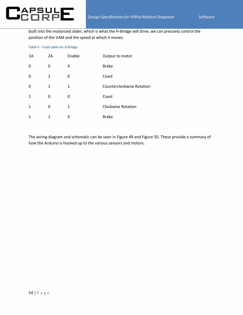
Design Specification for PillPal Medical Dispenser Software
54 | P a g e
built into the motorized slider, which is what the H-Bridge will drive, we can precisely control the
position of the VAM and the speed at which it moves.
Table 5 - Truth table for H-Bridge
1A 2A Enable Output to motor
0 0 X Brake
0 1 0 Coast
0 1 1 Counterclockwise Rotation
1 0 0 Coast
1 0 1 Clockwise Rotation
1 1 X Brake
The wiring diagram and schematic can be seen in Figure 49 and Figure 50. These provide a summary of
how the Arduino is hooked up to the various sensors and motors.

Design Specification for PillPal Medical Dispenser Software
55 | P a g e
Figure 49 - Wiring Diagram Overview for Arduino

Design Specification for PillPal Medical Dispenser Software
56 | P a g e
Figure 50 - Schematic Diagram Overview for Arduino
The Arduino code itself is broken up into two sections. There is the setup() function, which is run once
during the Arduino’s boot-up, and then there is the main loop(), which is simply a continuous loop the
Arduino will continuously run through, as is typically the case in most embedded systems. This is very
useful for us to handle errors from power loss and improper shut downs. Using the setup() function, we
can ensure that all mechanical components are set to their zero positions, for example the VAM is
retracted, the VAM is aligned with a compartment, and the garbage pill selector is in the correct position
to wait for pills, before resuming normal operation in the loop(). This ensures that the mechanical
systems are ready to go when needed and will greatly increase the repeatability for these systems.

Design Specification for PillPal Medical Dispenser Software
57 | P a g e
The boot up sequence is only one of the ways we intend to ensure that the mechanical components will
function safely for the user as well as ensuring that there will be no mechanical failures. While running
in normal operation mode, we intend to ensure only one component is used at a time. That means when
the Raspberry Pi needs to interact with the VAM, the SPC, or the Fingerprint reader, the Arduino will
purely focus on that task. We do this by putting in a hardware mutex of sorts so that the Arduino can
only access one piece of hardware at a time until the hardware is done being used and is in a safe
operating state. This is particularly important for interactions between the VAM and the SPC since if the
SPC begins to rotate while the VAM is extended, the VAM could be critically damaged and thus we need
to ensure such a situation does not arise. Also, since the Fingerprint uses a software serial connection to
fetch and send data, the Arduino needs to constantly monitor the transmitting and receiving pins in
order to transceive the data correctly. Because of these possible errors, the simplest solution is to simply
have the Arduino perform one task to completion, or until the user sends a cancel command, before
moving onto the next set of instructions.
In order for the Raspberry Pi to communicate efficiently with the Arduino using the Arduino, we need to
carefully predefine how the data exchanged will be formatted. Since the UART will exchange byte sized
messages, we will limit the size of each command to 8-bits to keep things simple so there will be no
need to handle exchanging multi-byte messages. With this in mind, tasks can be divided into tasks
related to the VAM, the SPC, the Label Reader, the Fingerprint Reader, or general querying and error
passing. Having 4 main categories for commands, we feel it is appropriate to have a 2-bit header to
identify the type of commands given and using the remaining 6-bits to specify the exact command and
associated parameters required. This will make it easier to debug since each message can be easily
broken down into two parts to identify commands quickly, and this makes it easier to modularize the
Arduino code for testing and implementation purposes. The message design can be seen below Table 6.
Table 6 - UART Framing bits
Type Header Body
Bit Number 7 6 5 4 3 2 1 0
This allows us to have up to 4 types of commands with 64 different commands each.
As of now, we have broken tasks up as follows:

Design Specification for PillPal Medical Dispenser Software
58 | P a g e
Table 7 – Commands to be decoded for Arduino
TASK Required Functionality
General Debugging information for task (Verbose or Brief information for everything)
Cancel Commands and Verification where applicable
Query for Arduino busy (time’s out when busy)
VAM Grab Pill
o Return Pill grabbed at VAM extension length Y
o Return fail code if Pill Counter does not detect Pill after 3 tries
o Return no pills detected (VAM reaches maximum extension length and
is unable to pick up any pills)
Check number of pills remaining
o Return length VAM extends to estimate remaining pills
SPC Go to Bottle X in direction Z
o Return Confirmation/Failure (echo Bottle number on success)
Go to nearest Container in Direction Z
o Return Bottle number Y reached
Label Reader Rotate Bottle X amount in direction Z
o Return Success/Failure when attempt is complete
Fingerprint
Reader
Send check status command
o Return whether or not Fingerprint reader is detected and password
verification has passed
Return status of Fingerprint reader
o Return if Fingerprint reader is detected and password verification is
successful
Enrolment command with accompanying fingerprint slot number
o Return Ready command when reader is ready for fingerprint
o Return Success when Fingerprint detected, snapshot taken, and
fingerprint needs to be removed
o Return when Fingerprint check is required for verification and
completion of enrollment
Send command to check fingerprint
o Return ID number for fingerprint that is detected and confidence value
o Return Failure codes according to failure type
Send clear all memory command for first time boot to clear enrolled
fingerprints

Design Specification for PillPal Medical Dispenser Software
59 | P a g e
The following figures give a high level overview of the Arduino code: Figure 51, Figure 52, Figure 53,
Figure 54, Figure 55, and Figure 56 .

Design Specification for PillPal Medical Dispenser Software
60 | P a g e
Figure 51 - Arduino Boot up flow chart

Design Specification for PillPal Medical Dispenser Software
61 | P a g e
Figure 52 - Arduino Main Loop flow chart

Design Specification for PillPal Medical Dispenser Software
62 | P a g e
Figure 53 - Arduino Finger Print Reader flow chart

Design Specification for PillPal Medical Dispenser Software
63 | P a g e
Figure 54 - Arduino Label reader flow chart
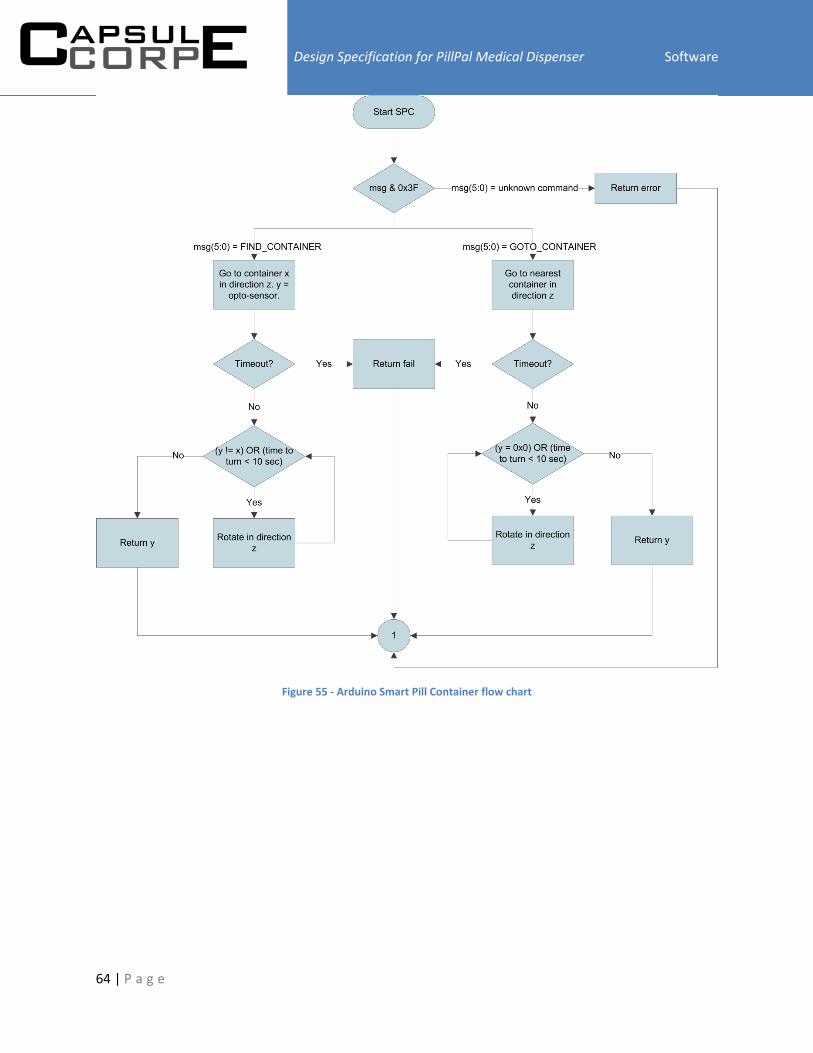
Design Specification for PillPal Medical Dispenser Software
64 | P a g e
Figure 55 - Arduino Smart Pill Container flow chart

Design Specification for PillPal Medical Dispenser Software
65 | P a g e
Figure 56 - Arduino Vacuum Arm Manipulator flow chart
Design Specification for PillPal Medical Dispenser Test Plan
66 | P a g e
Task: Test the ability to navigate through each menu of the GUI using the “back”, “home”, and
“Finish”/”Done” buttons Test Steps:
1. Go through each menu and press the back button
2. Go through each menu and press the home button
3. In appropriate menus press the finish/done button
Expected Result: Pressing the back button should take you to the previous menu. Pressing the home
button should take you to the home menu. Pressing the finish/done button should take you to the main
previous menu.
Task: Test the functionality of the buttons on the home menu Test Steps:
1. Press each button on the home screen
Expected Result: Each button takes the user to its appropriate menu. The general details of the next
scheduled pill are displayed on the home screen and pressing it takes the user to the calendar with
further details of the pill given.
Task: Test the ability to go through the steps to load pills and edit prescription information Test Steps:
1. From the home menu press the “Load Pills” button
2. In the subsequent menu press the “Start” button and wait for the system to load the pills
3. Once the pills are loaded verify prescription information read from the medical label
4. Edit information and press the “Next” button
5. Add the times to take the pills and press the “Finish” button
Expected Results: Pressing the “Load Pills” button should take the user to a confirmation screen.
Pressing “Start” in the confirmation screen should start the process of loading the pills and reading the
medical label. Once that is done all relevant information read from the medical label is displayed in
editable fields. User is able to edit each field through the virtual keyboard. When the user presses the

Design Specification for PillPal Medical Dispenser Test Plan
67 | P a g e
“Next” button a menu with the option to select time for each number of pills to be taken in a day is
displayed. The user is able to edit the times. When the user presses “Finish” he is taken to the home
screen and all the pill information is stored in the schedule and viewable through the calendar and user
settings menus.
Task: Test the ability to go through steps to dispense the pills Test Steps:
1. From the home menu press the “Dispense Pills” button
2. In the subsequent menu press the “Dispense” button and wait for the system to dispense the
pills
3.
Expected Result: Pressing the “Dispense Pills” button should take the user to a confirmation screen. This
confirmation screen should display the name of the pill to be taken, the dosage, as well as other
information such as whether to take it with food. Pressing “Dispense” in the confirmation screen should
start the process of dispensing the pills. Once the pills have been dispensed the user is taken to the
home menu.
Task: Test the functionality of the calendar and the schedule Test Steps:
1. From the home menu press the “Calendar” button
2. In the subsequent menu press on one of the dates shown in the monthly calendar
3. In the list of times select a time
4. In the list of prescriptions select a prescription
Expected Result: Pressing the “Calendar” button should take the user to the calendar menu. This menu
should contain a monthly calendar, a list of times, a list of prescriptions, and a details pane. Pressing
each date on the calendar should display a list of times that pills are scheduled for on that day. Pressing
each scheduled time should display a list of prescriptions that are scheduled to be taken at that time.
Pressing each prescription should display all its relevant details such as prescription number, prescribing
doctor name, date of prescription, dosage, quantity of pills, strength, and whether to take it with food
on the details pane.
Task: Test the functionality of the WiFi connectivity and settings Test Steps:
Design Specification for PillPal Medical Dispenser Test Plan
68 | P a g e
1. From the home menu press the “Settings” button
2. In the subsequent menu press the “WiFi Settings” button
3. Choose an access point to connect to from the list
4. Press the “Connect” button
5. If access point requires a password, enter the password and again press the “Connect” button in
the subsequent menu
Expected Result: Pressing the “Settings” button should take the user to the settings menu that displays
all the user and system settings. Pressing the “WiFi Settings” button should take the user to the WiFi
settings menu. A list of access points with range and the type of encryption is displayed. Selecting an
access point and pressing the “Connect” button should automatically connect to the access point and
update the status on the taskbar if no password is required. Otherwise it takes the user to a prompt
screen that asks the user to enter the password and then press “Connect”. The taskbar should update
depending on whether the connection was successful or not. WiFi information is saved so device
automatically connects next time it boots.
Task: Test the functionality of the brightness settings Test Steps:
1. From the home menu press the “Settings” button
2. In the subsequent menu press the “Brightness” button
3. Move the slider to adjust the brightness
Expected Result: Pressing the “Settings” button should take the user to the settings menu that displays
all the user and system settings. Pressing the “Brightness” button should take the user to the brightness
menu. Moving the slider should adjust the brightness of the touch screen accordingly. The position of
the slider should be saved automatically and be in the same position if leaving and reentering the
brightness menu.
Task: Test the functionality of the alarms settings Test Steps:
1. From the home menu press the “Settings” button
2. In the subsequent menu press the “Alarms” button
3. Choose an alarm from the drop down menu
4. Move the slider to adjust the volume
5. Press the “Preview” button
Expected Result: Pressing the “Settings” button should take the user to the settings menu that displays
all the user and system settings. Pressing the “Alarms” button should take the user to the alarms menu.

Design Specification for PillPal Medical Dispenser Test Plan
69 | P a g e
Moving the slider should adjust the volume of the operating system accordingly. Once “Preview” is
pressed the chosen alarm should play at the chosen volume. The chosen alarm and position of the slider
should be saved automatically and be in the same position if leaving and reentering the alarms menu.
Task: Test the functionality of the outside alerts settings Test Steps:
1. From the home menu press the “Settings” button
2. In the subsequent menu press the “Outside Alerts” button
3. Edit all relevant information about the emergency contact and when and how to contact them
Expected Result: Pressing the “Settings” button should take the user to the settings menu that displays
all the user and system settings. Pressing the “Outside Alerts” button should take the user to the outside
alerts menu. All fields should be editable. Virtual keyboard is displayed when trying to edit fields. All
information is saved automatically.
Task: Test the functionality of the user settings Test Steps:
1. From the home menu press the “Settings” button
2. In the subsequent menu press the “User Settings” button
3. From the list of users choose a user that is the current user
4. Press the “Edit” button and edit all the user information
5. Go back to the user settings menu and press the “View Prescriptions” button and modify times
to take the pill
6. Go back to the user settings menu and press the “New” button
7. Enter a username and press the “Next” button
8. Enter user information
9. Go back to the user settings menu and press the “Delete” button
10. Choose a user that is not the current user
11. Press the “Sign In” button
Expected Result: Pressing the “Settings” button should take the user to the settings menu that displays
all the user and system settings. Pressing the “User Settings” button should take the user to the user
settings menu. The current user should be displayed in the taskbar. All buttons should be enabled when
choosing the current user. Pressing the “Edit” button should take the user to a menu that has text fields
to enter user information that activate the virtual keyboard when pressed. Pressing the “View
Prescriptions” button shows a list of all prescriptions that the user has and selecting a prescription
shows details in a details pane. The user also has the ability to modify times to take the pills. Pressing

Design Specification for PillPal Medical Dispenser Test Plan
70 | P a g e
the “New” button takes the user to a menu with an editable text field to enter a username through the
virtual keyboard. Pressing “Next” in this screen takes the user to the same menu as when pressing the
“Edit” button. Pressing the “Delete” button deletes the user and the user that is the default user is
automatically assigned as the current user. Choosing a user that is not the current user disables all
buttons except the “New” and “Sign In” button. Pressing the “Sign In” button makes the selected user
the current user. The taskbar and calendar are updated with the newly signed-in user’s username and
schedule. All user information in each menu should automatically be saved. The list under “User
Settings” is updated for any new/deleted users. Cannot add user with same username.
Task: Test the functionality of the alarms to notify user to dispense pills Test Steps:
1. Have a pill loaded into the device and scheduled
2. Wait for the scheduled time to occur
3. Go to the dispense menu and press “Dispense”
Expected Result: When the scheduled time arrives the user selected alarm should start ringing. The
alarm should keep ringing until the given time to send an emergency delay. Going to the dispense menu
and pressing “Dispense” should turn off the alarm.
Task: Test the functionality of the alarms to notify emergency contacts Test Steps:
1. Have a pill loaded into the device and scheduled
2. Wait for the scheduled time to occur
3. Wait until the user specified emergency delay time
Expected Result: When the scheduled time arrives the user selected alarm should start ringing. The
alarm should keep ringing until the given time to send an emergency delay. After the specified
emergency delay time by the user, and emergency alert should be sent to the user specified emergency
contact through the user specified medium.
Task: Test that the Vacuum turns on when required for VAM.
Test Steps:
1. Tell VAM to pick up pill smallest pill

Design Specification for PillPal Medical Dispenser Test Plan
71 | P a g e
2. Tell VAM to pick biggest pill
3. Tell VAM to pick heaviest pill
4. Test different orientation of the pill.
Expected results: PillPal should pick up and release the different sized pills in all different orientation.
Task: Test that will ensure that the VAM can detect Pill containers
Test Steps:
1. Misalign SPC
2. Tell VAM to go to nearest pill container in direction 1
3. Misalign SPC
4. Tell VAM to go to nearest pill container in direct 2
Expected Results: VAM will rotate in direction 1 until the first pill container is aligned . Then it will rotate
in direction 2 and find the adjacent pill container in opposite direction,
Task: Test that will check that the VAM is capable of selecting correct Pill Container
Test Steps:
1. Tell VAM to align SPC
2. Tell VAM to go the container in opposite side going clockwise
3. Tell VAM to return to original container going counter clockwise
4. Tell VAM to return to opposite container going counterclockwise
Expected Results: SPC will rotate 180 degrees clockwise, then 180 degrees counterclockwise and then
another 180 degrees counter clockwise, stopping briefly when VAM is aligned with two of the
containers.
Task: Ensure VAM extends and retracts correctly and at the desired distance.
Test Steps:
1. Use serial commands to get the Arduino to operate the sliding mechanism.
2. Send commands to move the VAM to different distances and measure the outcome.
3. Get VAM to try and get pill from empty container

Design Specification for PillPal Medical Dispenser Test Plan
72 | P a g e
4. Get VAM to try and get pill from full container
Expected Results: We expect the VAM to move to precise distance markers as it has a potentiometer
feedback and the code controlling the VAM should be able to compensate for any deviations.
In first case, VAM will fully extend and then retract once it hits bottom of container. In second case,
VAM will extend slightly before beginning to retract once it detects container is full.
Task: Ensure the pill bottle rotates as the stepper rotates
Test Steps:
1. Instruct Arduino to send the stepper motor command via serial commands.
2. Start with ⅛ steps size with small number of steps at a slow speed.
3. Increase the number of steps taken.
4. Increase the speed of stepping.
Expected Results: We should be able to rotate the pill bottles using rubber wheel at a slow speed and
small step sizes. We want to be able to maintain accuracy but also rotate the bottle at a reasonable
speed. Thus we shall test and obtain the fastest speed of rotation before it fails to rotate the pill bottle
as expected.
Task: To ensure the quality of the pictures taken.
Test Steps:
1. Connect Arduino to the PC directly and use the serial port to send commands to the Arduino.
2. Turn the Illumination LED light on, to ensure proper and even lighting situation.
3. Instruct the Arduino to focus properly.
4. Instruct the Camera to take the picture.
Expected Results: We expect good picture quality with proper lighting, taken at a 90 degree angle. We
do not want the picture to be skewed as it will affect our results in stitching multiple images together
and OCR.

Design Specification for PillPal Medical Dispenser Test Plan
73 | P a g e
Task: Test that the Pill counter will detect when more than one pill is dropped
Test Steps:
1. Disconnect Vacuum
2. Get PillPal to fetch one pill from somewhere
3. When VAM retracts, dump two pills into funnel for dispenser
Expected Result: Pill Dispenser will dump both pills into Garbage Bin
Task: Test that the dispenser will not dispense pills when dispensing cup is missing
Test Steps:
1. Remove dispensing Cup
2. Tell PillPal to fetch a pill
Expected Result: Pill Dispenser will dump fetched pill(s) into into Garbage bin after slight delay.
Raspberry Pi will receive “Dispensing Cup Missing Error”

Design Specification for PillPal Medical Dispenser Finances
74 | P a g e
A summary of our finances, including expedited shipping time to speed up development time can be
seen in Table 8 - Financial Summary
Table 8 - Financial Summary
Hardware Cost Tax and Shipping
HomeDepot-Building Mics plexi $45.90 $5.51
HomeDepot - Acrylic Sheet $37.06 $4.45
SPD-SI GEARS x6 $16.93 $23.91
Stepper $41.35 $4.96
Vacuum ( for prototyping) $25.00 $3.00
$166.24 $41.83 Sub Total
$208.07 Total
Electronics and MCU & Pi Miscs Cost Tax and Shipping
Digi-KEY - Sensors and Miscs $51.24 $16.91
Servo-City 0 Servo Gears - Mounting
$50.06 $61.08
SDHC 8GB- C10 $6.99 $0.84
WI-FI N USB $9.99 $1.20
Finger Print Reader+ PI $114.90 $13.35
Spark Fun - Stepper, Drivers, Miscs $66.54 $46.34
Coaxil Power DC cable $2.10 $6.25
OSEPP Uno R3 Plus $29.95 $3.59
TouchScreen 10" LCD LVDS-PI $128.49 $55.00
HP 3100 Webcam 720p $9.99 $1.65
Belkin Hub 7 Port USB 2.0 $24.99 $3.00
$495.24 $209.21 Sub Total
$704.45 Total
$912.52 Final Total

Design Specification for PillPal Medical Dispenser Conclusion
75 | P a g e
The design specification is written to highlight and give specific dimensions for the design and making of
PillPal. Based on the functional specification documentation, the design specification will serve as a
guideline when implementing all functional requirements. With the provided clear and concise
information we are expected to complete a working proof-of-concept by the April 22nd, 2013.
[1] ClarkeContainer, "Products - Pharmacy - Bottles and Viles," [Online]. Available:
http://www.clarkecontainer.com/products-pharmacy.asp. [Accessed 07 March 2013].
[2] API Technologies, "Plastic Photodiode Packages with Leads," Advance Photonix Inc., California.
[3] Omron, "Photomicrosensor-EE-SX3070," Omron.
[4] Texas Instruments, "SN54HC595 8-bit Shift Register," Texas Instruments, Dallas, 2004.
[5] CircuitLab Inc., "Circuit Lab - An Online Circuit Simulator," 2013. [Online]. Available:
https://www.circuitlab.com/. [Accessed 05 March 2013].
[6] Texas Instruments, "TL081 JFET-input Operational Amplifiers," Texas Instruments, Dallas, 2004.
[7] Advanace Micro Control, "AMCI Tech Tutorial," 2012. [Online]. Available:
http://amci.com/tutorials/tutorials-stepper-vs-servo.asp. [Accessed 02 03 2013].
[8] Woodweb, "servo vs stepper motors," 2013. [Online]. Available:
http://www.woodweb.com/knowledge_base/Servo_vs_stepper_motors.html. [Accessed 02 03
2013].
[9] "Roboticera," BlogSpot, [Online]. Available: http://roboticera.blogspot.ca/2007/08/lets-start-by-
looking-at-overall-plan.html. [Accessed 05 March 2013].
[10] Leo-Sales, "Metal-Gear Digital Servo," Leo-Sales, Vancouver.

Design Specification for PillPal Medical Dispenser References
76 | P a g e
[11] AllegroMicrosystems, "A3967 Motor Driver," Allegro MicroSystems, Worecester, 2007.
[12] SparkFun Electronics, "EasyDriver Stepper Motor Driver," 2012. [Online]. Available:
https://www.sparkfun.com/products/10267. [Accessed 07 March 2013].
[13] Top-Up Industry Corp, "100mm Motor Slide with Potentiometers," Top-Up Industry Corp, 2008.
[14] HP, "HP HD-3110 Webcam Troubleshooting - Drivers and Support," HP, [Online]. Available:
http://h10025.www1.hp.com/ewfrf/wc/document?docname=c02571562&tmp_task=prodinfoCate
gory&cc=us&dlc=en&lc=en&product=4172475. [Accessed 09 March 2013].
[15] Dlink Systems, "7-Port USB 2.0 Hub," Dlink Systems, 2011.
[16] LG Corp, "LP101WX1 - Liquid Crystal Display," LG Corp.
[17] Chalkboard Electronics, "Chalkboard Electronics," 2012. [Online]. Available: http://www.chalk-
elec.com/. [Accessed 17 02 2013].
[18] Arduino, "Arduino," [Online]. Available: http://www.arduino.cc/. [Accessed 01 03 2013].
[19] Arduino, "SoftwareSerial," Arduino, [Online]. Available: http://arduino.cc/en/Tutorial/HomePage.
[Accessed 10 March 2013].
[20] AA Portable Power Corp, "Powerizer- Li-Ion Battery," 2013. [Online]. Available:
http://www.batteryspace.com/polymerli-ionbattery148v5ah74wh7arate.aspx. [Accessed 07 March
2013].
[21] l. ada, "Github," 12 2012. [Online]. Available: https://github.com/adafruit/Adafruit-Fingerprint-
Sensor-Library. [Accessed 27 02 2013].
[22] SDP/SI, Molded Spur Gear - DataSheet, SDP/SI.
[23] Wikipedia, "Poly(methyl methacrylate)," 25 March 2012. [Online]. Available:
http://en.wikipedia.org/wiki/Poly(methyl_methacrylate). [Accessed 07 March 2013].
[24] G. Elert, "Density of Glass," 2004. [Online]. Available:
http://hypertextbook.com/facts/2004/ShayeStorm.shtml. [Accessed 7 March 2013].
[25] HomeDepot, "Clear Acrylic Sheet," [Online]. Available: http://www.homedepot.ca/product/clear-
acrylic-sheet-118-inch-x-36-inch-x-72-inch/924845. [Accessed 07 March 2013].
[26] Texas Instruments, "SN754410 Quadruple Half-H Driver," Texas Instruments, Dallas, 1995.

Design Specification for PillPal Medical Dispenser References
77 | P a g e
[27] Digia, "Product - Digia Plc," 2013. [Online]. Available: http://qt.digia.com/product/. [Accessed 12
March 2013].
[28] Wikipedia, "Qt (framework) - Wikipedia, the free encyclopedia," December 2012. [Online].
Available: http://en.wikipedia.org/wiki/Qt_(framework). [Accessed 12 March 2013].
[29] G. Romano, "VirtualKeyboard - QtApps.org," 27 March 2012. [Online]. Available: http://qt-
apps.org/content/show.php/VirtualKeyboard?content=107388. [Accessed 1 March 2013].
[30] Google, "tesseract-ocr - An OCR Engine that was developed at HP Labs between 1985 and 1995...
and now at Google.," [Online]. Available: http://code.google.com/p/tesseract-ocr/. [Accessed 11
March 2013].
[31] R. Smith, "Tesseract OCR Engine," Google Inc, Mountain View, 2007.
[32] Wikipedia, "XML - Wikipedia, the free encyclopedia," 9 March 2013. [Online]. Available:
http://en.wikipedia.org/wiki/XML. [Accessed 14 March 2013].
[33] Refsnes Data, "XML Introduction - What is XML?," 2013. [Online]. Available:
http://www.w3schools.com/xml/xml_whatis.asp. [Accessed 12 March 2013].
[34] Wikipedia, "Universal Asynchroous receiver/transmitter," 13 February 2013. [Online]. Available:
http://en.wikipedia.org/wiki/Uart. [Accessed 10 March 2013].
[35] KylesConverters, "Convert Inches of Mercury to Bars," KylesConverters, [Online]. Available:
http://www.kylesconverter.com/pressure/inches-of-mercury-to-bars. [Accessed 10 March 2013].

Design Specification for PillPal Medical DispenserAppendix – Hardware Test Checklist
78 | P a g e
Hardware
1. Electrical and Mechanical
Power Supply Rails are
within 10%: 12V, 5V, 3V:
Yes ____ No ____
Power Cord is
detachable:
Yes ____ No ____
Speaker is able to
achieve 90 dB:
Yes ____ No ____
Motors are secure and
operate without
significant vibration:
Yes ____ No ____
Rotational devices are
secure and rotate freely
without resistance:
Yes ____ No ____
Noise levels are below
60 dB:
Yes ____ No ____
Laser is secure and does
not pose a threat to the
user:
Yes ____ No ____
VAM is able to pick up a
single pill at a time:
Yes ____ No ____
VAM is able to drop the
pill precisely 99% of the
time:
Yes ____ No ____
Stepper Motor
dispensing safety
stopping mechanism is
able to accurately
discard or dispense the
desired medication:
Yes ____ No ____
Laser Sensor is able to
trigger on object sliding
Yes ____ No ____
Comments:

Design Specification for PillPal Medical DispenserAppendix – Hardware Test Checklist
79 | P a g e
by:
Power supply can supply
sufficient current to run
all the motors:
Yes ____ No ____
Devices do not restart
or fail when the vacuum
motor starts and stop:
Yes ____ No ____
VAM is able to have
feedback about the
relative position:
Yes ____ No ____
VAM is able to detect
when it touches objects
when it is extending:
Yes ____ No ____
Pills empty completely
into our storage
container:
Yes ____ No ____
Each storage containers
are uniquely and
accurately identified by
our Photo micro sensor:
Yes ____ No ____
2. Arduino Controls
Able to clearly display
its current control state
back to the Pi.
Yes ____ No ____
Able to control stepper
motor via the
EasyDriver.
Yes ____ No ____
Can accurately send
commands to the
stepper.
Yes ____ No ____
Arduino have fast
executing main loop
code and interrupt code
without missing external
hardware interrupt
Yes ____ No ____
Comments:

Design Specification for PillPal Medical DispenserAppendix – Hardware Test Checklist
80 | P a g e
signals.
Able to communicate
with the fingerprint
scanner and
authenticate users.
Yes ____ No ____
Can successfully control
both servo motors and
obtain accuracy and
repeatability.
Yes ____ No ____

Design Specification for PillPal Medical DispenserAppendix – Software Test Checklist
81 | P a g e
Software
3. GUI
Taskbar shown in every
menu:
Yes ____ No ____
Taskbar displays current
date and time:
Yes ____ No ____
Taskbar displays
username of current
user:
Yes ____ No ____
Taskbar displays WiFi
connectivity status:
Yes ____ No ____
All menus navigable
aside from
waiting/progress
menus?
Yes ____ No ____
All editable fields such
as text edits display on-
screen virtual keyboard
when pressed:
Yes ____ No ____
All editable fields can be
modified by what the
user types on the virtual
keyboard:
Yes ____ No ____
Virtual keyboard maps
buttons to text
correctly:
Yes ____ No ____
Home menu displays
next scheduled pill:
Yes ____ No ____
Home menu buttons
have icons:
Yes ____ No ____
Ask for confirmation Yes ____ No ____
Comments:

Design Specification for PillPal Medical DispenserAppendix – Software Test Checklist
82 | P a g e
before loading pills:
Ask for confirmation
before dispensing pills:
Yes ____ No ____
Show details of pill to
dispense in dispensing
confirmation:
Yes ____ No ____
Waiting/progress menus
displayed when
Raspberry Pi is
communicating with the
Arduino:
Yes ____ No ____
Displays the schedule in
a monthly calendar:
Yes ____ No ____
Able to view times and
prescriptions in each
time for a particular day
chosen in the monthly
calendar:
Yes ____ No ____
Displays OCR results in
editable fields:
Yes ____ No ____
Allows user to edit OCR
results:
Yes ____ No ____
Displays nearby access
points in WiFi settings:
Yes ____ No ____
Displays prompts to
enter passwords when
and where applicable:
Yes ____ No ____
Displays lists of users: Yes ____ No ____
Displays menus for user
settings/control:
Yes ____ No ____
Displays user’s
prescriptions as read-
only:
Yes ____ No ____

Design Specification for PillPal Medical DispenserAppendix – Software Test Checklist
83 | P a g e
Displays menus for
system settings:
Yes ____ No ____
Displays “About”
information:
Yes ____ No ____
4. Raspberry Pi to Arduino communication
Arduino can echo what
Raspberry Pi sends:
Yes ____ No ____
Raspberry Pi can signal
Arduino to start loading
pills:
Yes ____ No ____
Raspberry Pi can signal
Arduino to start
dispensing pills:
Yes ____ No ____
Comments:
5. User Settings
Can create a user: Yes ____ No ____
Cannot create a user
with duplicate
usernames:
Yes ____ No ____
Can only edit signed-in
user:
Yes ____ No ____
Can only view
prescriptions of signed-
in user:
Yes ____ No ____
Can sign into another
user:
Yes ____ No ____
Signing in requires
authentication through
fingerprint reader:
Yes ____ No ____
Default user
automatically signed in
at system bootup:
Yes ____ No ____
Can only delete signed-
in user:
Yes ____ No ____
Comments:

Design Specification for PillPal Medical DispenserAppendix – Software Test Checklist
84 | P a g e
Deleting default user
automatically assigns
another user as default
arbitrarily:
Yes ____ No ____
Raspberry Pi can signal
Arduino to start
dispensing pills:
Yes ____ No ____
6. Schedule
Software determines
how many days to take
the pill based on
prescription date,
dosage, number of pills,
and how many to take
per day (frequency):
Yes ____ No ____
User able to specify pill
times for each pill when
loading:
Yes ____ No ____
Pill times are modifiable
after loading:
Yes ____ No ____
Able to take multiple
pills of multiple
prescriptions on the
same day and time:
Yes ____ No ____
Cannot schedule
duplicate prescriptions
if date ranges overlap:
Yes ____ No ____
Prescriptions removed
from schedule once
they are finished:
Yes ____ No ____
Comments:
7. System Settings
Adjust brightness of
screen:
Yes ____ No ____
Adjust volume of
Raspberry Pi OS:
Yes ____ No ____
Comments:
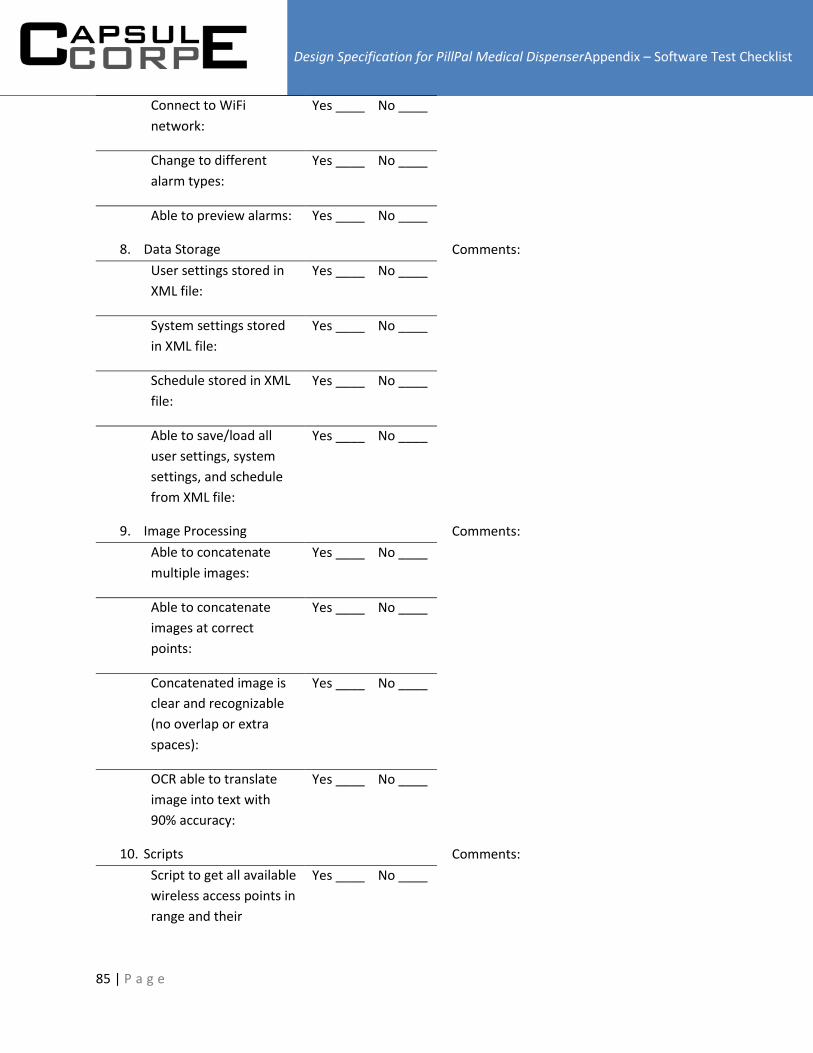
Design Specification for PillPal Medical DispenserAppendix – Software Test Checklist
85 | P a g e
Connect to WiFi
network:
Yes ____ No ____
Change to different
alarm types:
Yes ____ No ____
Able to preview alarms: Yes ____ No ____
8. Data Storage
User settings stored in
XML file:
Yes ____ No ____
System settings stored
in XML file:
Yes ____ No ____
Schedule stored in XML
file:
Yes ____ No ____
Able to save/load all
user settings, system
settings, and schedule
from XML file:
Yes ____ No ____
Comments:
9. Image Processing
Able to concatenate
multiple images:
Yes ____ No ____
Able to concatenate
images at correct
points:
Yes ____ No ____
Concatenated image is
clear and recognizable
(no overlap or extra
spaces):
Yes ____ No ____
OCR able to translate
image into text with
90% accuracy:
Yes ____ No ____
Comments:
10. Scripts
Script to get all available
wireless access points in
range and their
Yes ____ No ____
Comments:

Design Specification for PillPal Medical DispenserAppendix – Software Test Checklist
86 | P a g e
encryption settings:
Script to connect to
wireless access point
with password:
Yes ____ No ____
Script to control touch
screen brightness:
Yes ____ No ____
Script to adjust
Raspberry Pi OS volume:
Yes ____ No ____