design standards ysm appendix section v. division 15 hvac
TRANSCRIPT
DESIGN STANDARDS
YSM APPENDIX
Section V. Division 15 HVAC
January 20, 2010
Yale University – School Of Medicine Facilities Construction & Renovation
2
DIVISION 15: HVAC INDEX
15058 MOTORS
15059 STARTERS
15060 DRIVES
15083 PIPE FITING AND VALVE INSULATION
15084 DUCT INSULATION (EXTERNAL)
15112 VALVES
15113 STRAINERS
15114 SUCTION DIFFUSERS
15127 PRESSURE GAUGES, THERMOMETERS AND TEST PLUGS
15181 PIPING AND FITTINGS
15182 STEAM PRESSURE REDUCING VALVES
15185 CENTRIFUGAL PUMPS
15186 DUPLEX CONDENSATE PUMP SET
15187 STEAM TRAPS
15189 CHEMICAL TREATMENT
15211 CONTROL AIR PIPING POLICY
15630 AIR COOLED WATER CHILLERS
15725 CENTRAL STATION AIR HANDLING UNITS
15726 BUILT-UP AIR HANDLER
15727 AIR HANDLING UNITS WITH COILS
15735 SELF-CONTAINED THROUGH-WALL AIR CONDITIONING UNITS
15738 SPLIT SYSTEM DIRECT EXPANSION AIR CONDITIONING
15745 CONSOLE HEAT PUMP
15746 CEILING-MOUNTED HEAT PUMP
15752 HUMIDIFIERS
15762 HOT WATER (STEAM) CABINET HEATERS
15762 AIR-COOLED CONDENSER
15763 FAN COIL UNITS
15766 (HOT WATER) (STEAM) UNIT HEATERS
15766 ELECTRIC UNIT HEATERS
15767 ELECTRIC CABINET HEATERS
15815 DUCTWORK AND AIR DISTRIBUTION EQUIPMENT
15835 BELTED VENT SET
15836 HIGH-PLUME DILUTION FANS
15837 CENTRIFUGAL FANS
15838 CENTRIFUGAL FANS FOR ROOF CENTRAL EXHAUST
TO ACCESS SECTION CLICK ON TITLE IN INDEX
3
15839 INLINE CENTRIFUGAL FANS
15840 VARIABLE VOLUME TERMINAL UNITS (HOSPITAL GRADE)
15841 LABORATORY AIR TERMINAL UNITS
15855 DIFFUSERS, REGISTERS AND GRILLES
15861 FILTERS MEDIUM EFFICIENCY, THROW AWAY TYPE
15862 CHARCOAL FILTERS FOR RADIOACTIVE APPLICATIONS
15866 FILTERS HIGH EFFICIENCY, THROW AWAY TYPE
15867 HIGH EFFICIENCY PARTICULATE AIR (HEPA) FILTER ASSEMBLIES
15868 BAG FILTERS FOR MEDICAL AND OTHER SPECIAL FACILITIES
15910 AUTOMATIC CONTROL, LOW LEAK DAMPERS
15950 TESTING, ADJUSTING AND BALANCING
16620 VARIABLE FREQUENCY DRIVES
17300 LABORATORY FUME HOOD FACE VELOCITY MONITOR

4
DIVISION 15 – HVAC

5
A. Unless otherwise specified, motors shall be NEMA Design B, constant speed, self-ventilated squirrel cage induction. Motors shall have 1.15 service factor unless totally enclosed. Motors shall have Class B insulation unless indicated otherwise. Motors shall be warranted by the manufacturer for a minimum period of 2 years
1. Motors under ½ HP, shall be designed for 120 V, 60 Hz, single phase, unless otherwise specified.
2. Motors ½ HP and over shall be as required in schedules.
B. Non-fractional HP Motors
1. Motors shall be totally enclosed-fan cooled (TEFC), and have inverter spike resistant (ISR) magnet wire. Open, drip proof motors included as part of package equipment will be acceptable if protected from moisture and dust infiltration as part of the package equipment assembly.
2. Motors shall have water tight shaft seals (field replaceable) and condensation drains, or weep holes.
3. Motor bearings for fan and compressor applications shall be belted load rated.
4. Grease fittings shall be provided for all non-sealed bearings.
5. Provide motors with oversized conduit box.
6. Motors 3HP and above shall have Class F insulation and cast iron frames and end plates.
7. Motors 20HP and larger shall have multiple lifting points incorporated in the casing to allow direct lifting to support mounting the motor base in the horizontal or vertical plain with the motor axis remaining horizontal.
8. For HVAC applications except steam condensate return, motor synchronous speed shall be 1,800 rpm. For steam condensate return pump applications 3,500 RPM may be used if required to meet YSM standard return pressure of 40 psig.
C. Motors for use with variable frequency drives (VFD's) shall be "inverter-duty" or "drive duty" motors, compatible with the drive to which it is connected. Use of the motor with a VFD shall not adversely affect the operation, useful life, or warranty of the motor.
1. Motors shall have Class F or H insulation.
2. Motor windings shall be spike resistant to withstand 1,600 peak volts.
3. The drive and motor shall be engineered to avoid the occurrence of shaft currents. Line reactors shall be employed (on all three legs of power feed between the drive and the motor) in lieu of shaft grounding.
4. Motors used with VFD shall have a minimum three (3) year warranty.
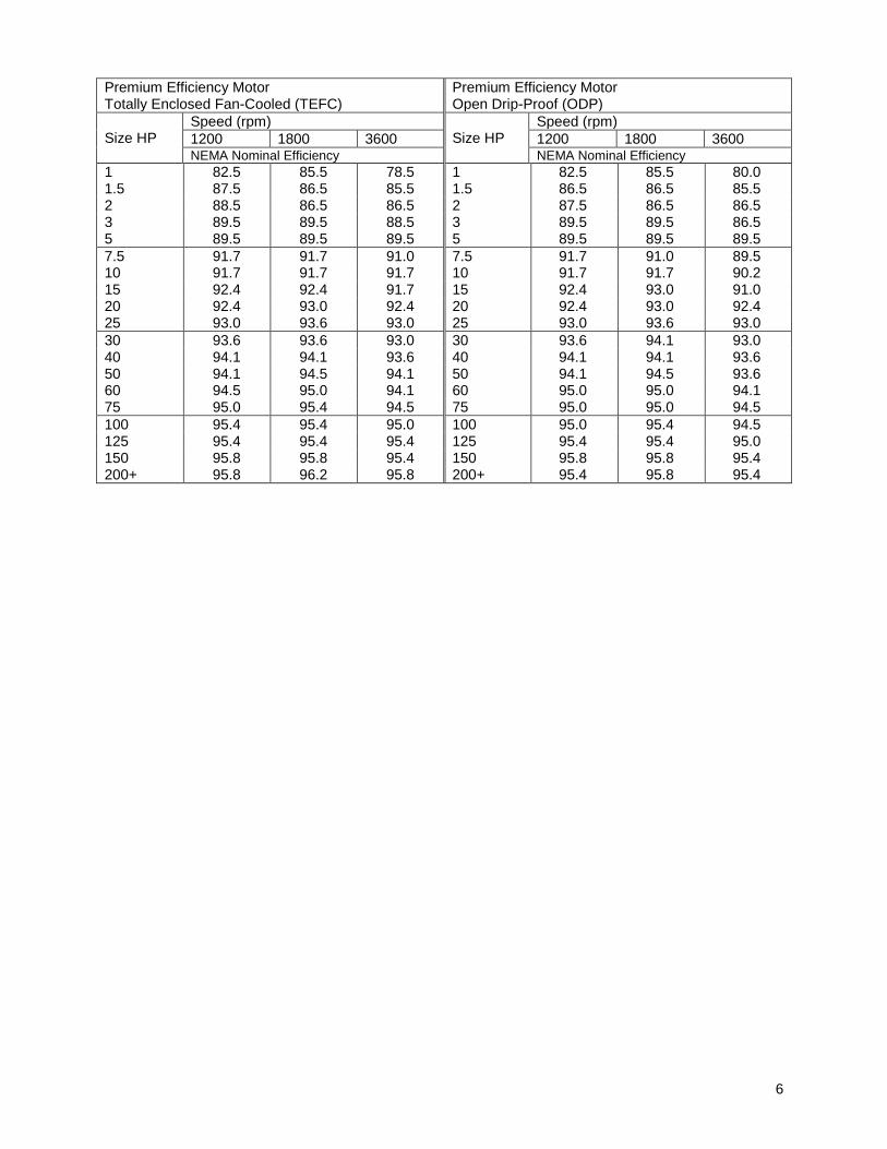
D. All motors shall be high or premium efficiency type. They shall conform to NEMA Standard MG-1-12.53a and shall have their efficiencies determined in accordance with IEEE Standard 112 Method B. The NEMA nominal efficiency shall be listed on the motor nameplate. Minimum nominal efficiencies shall be as follows:
6
Premium Efficiency Motor Totally Enclosed Fan-Cooled (TEFC)
Premium Efficiency Motor Open Drip-Proof (ODP)
Size HP Speed (rpm)
Size HP Speed (rpm)
1200 1800 3600 1200 1800 3600 NEMA Nominal Efficiency NEMA Nominal Efficiency
1 82.5 85.5 78.5 1 82.5 85.5 80.0 1.5 87.5 86.5 85.5 1.5 86.5 86.5 85.5 2 88.5 86.5 86.5 2 87.5 86.5 86.5 3 89.5 89.5 88.5 3 89.5 89.5 86.5 5 89.5 89.5 89.5 5 89.5 89.5 89.5
7.5 91.7 91.7 91.0 7.5 91.7 91.0 89.5 10 91.7 91.7 91.7 10 91.7 91.7 90.2 15 92.4 92.4 91.7 15 92.4 93.0 91.0 20 92.4 93.0 92.4 20 92.4 93.0 92.4 25 93.0 93.6 93.0 25 93.0 93.6 93.0
30 93.6 93.6 93.0 30 93.6 94.1 93.0 40 94.1 94.1 93.6 40 94.1 94.1 93.6 50 94.1 94.5 94.1 50 94.1 94.5 93.6 60 94.5 95.0 94.1 60 95.0 95.0 94.1 75 95.0 95.4 94.5 75 95.0 95.0 94.5
100 95.4 95.4 95.0 100 95.0 95.4 94.5 125 95.4 95.4 95.4 125 95.4 95.4 95.0 150 95.8 95.8 95.4 150 95.8 95.8 95.4 200+ 95.8 96.2 95.8 200+ 95.4 95.8 95.4

7
A. Starters that require interlocks or remote control shall be magnetic with HAND-OFF- AUTOMATIC switch (fast-slow-off-auto for two speed motors) in cover. Provide magnetic starters as necessary, with auxiliary contacts, buttons and switches in required configurations. Starters shall be by single manufacturer: Square D; G.E.; Westinghouse, Furnace, Allen Bradley and Cutler Hammer.
1. Each 3-phase, 60 Hz motor shall be provided with magnetic starter with either ON-OFF push button or hand-off-automatic switch. Also, lockable disconnects (for lock-out and tag-out).
2. Other motors shall be provided with a manual starter with ON-OFF switch. Also lockable disconnects (for lock-out and tag-out).
3. Control relay for each starter shall be for operation on 120 V, single phase, and transformer of sufficient capacity within starter case shall be furnished for this purpose.
4. Provide inverse time limit overload and under voltage protection in each leg and with pilot lights. Provide red and green On-Off pilot lights.
5. Provide starters for two-speed motors with deceleration relay.
6. Furnish for all single speed motors, 25 hp and above, 95% power factor correction capacitors. Capacitors shall be in NEMA enclosure of the same rating as the motor's starter.
8
A. Drives for belted motors shall be flame retardant and by Allis-Chalmers, Browning or Woods V-belt drives with adjustable motor sheave.
B. Sheaves shall be balanced statically and dynamically.
C. Fume hood exhaust drives shall be 2 groove (2 belt) minimum.
D. Belts shall be type AX or BX.
9
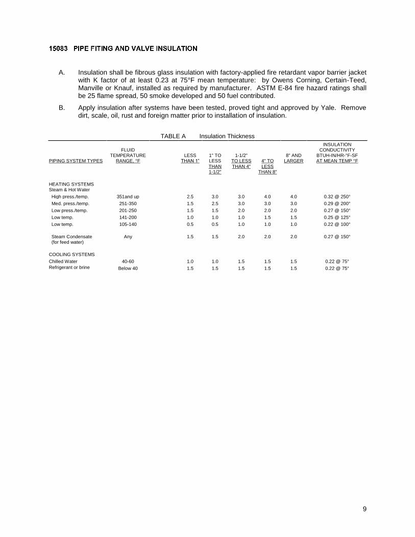
A. Insulation shall be fibrous glass insulation with factory-applied fire retardant vapor barrier jacket with K factor of at least 0.23 at 75°F mean temperature: by Owens Corning, Certain-Teed, Manville or Knauf, installed as required by manufacturer. ASTM E-84 fire hazard ratings shall be 25 flame spread, 50 smoke developed and 50 fuel contributed.
B. Apply insulation after systems have been tested, proved tight and approved by Yale. Remove dirt, scale, oil, rust and foreign matter prior to installation of insulation.
TABLE A Insulation Thickness PIPING SYSTEM TYPES
FLUID TEMPERATURE
RANGE, °F
LESS THAN 1”
1" TO LESS
THAN 1-1/2"
1-1/2" TO LESS
THAN 4"
4" TO
LESS THAN 8"
8" AND LARGER
INSULATION
CONDUCTIVITY BTUH-IN/HR-°F-SF AT MEAN TEMP °F
HEATING SYSTEMS Steam & Hot Water
High press./temp.
351and up
2.5
3.0
3.0
4.0
4.0
0.32 @ 250°
Med. press./temp.
251-350
1.5
2.5
3.0
3.0
3.0
0.29 @ 200°
Low press./temp.
201-250
1.5
1.5
2.0
2.0
2.0
0.27 @ 150°
Low temp.
141-200
1.0
1.0
1.0
1.5
1.5
0.25 @ 125°
Low temp.
105-140
0.5
0.5
1.0
1.0
1.0
0.22 @ 100°
Steam Condensate (for feed water)
Any
1.5
1.5
2.0
2.0
2.0
0.27 @ 150°
COOLING SYSTEMS
Chilled Water
40-60
1.0
1.0
1.5
1.5
1.5
0.22 @ 75°
Refrigerant or brine
Below 40
1.5
1.5
1.5
1.5
1.5
0.22 @ 75°

10
A. General
1. Insulation shall be Certain-Teed, Knauf, Manville or Owens Corning. Install insulation, mastics, adhesives, coatings, covers, weather-protection and other work exactly as required by manufacturer's recommendations. Materials shall meet requirements of Adhesive and Sealant Council Standards and SMACNA.
2. ASTM E-84 minimum fire hazard ratings shall be 25 flame spread, 50 fuel contributed and 50 smoke developed.
3. Insulation shall be continuous through wall and ceiling openings and in sleeves.
4. Transmission rates of vapor barriers shall not exceed 0.02 perms.
5. Kitchen exhaust duct shall be insulated with 2 hr. wrap by Thermal Ceramics, Unifrax Fyrewrap, 3M or equal and per NFPA and local code and fire dept. requirements.
B. Concealed Rectangular, Flat Oval and Circular Ductwork
1. Insulate supply and fresh air ducts and plena in concealed spaces and return duct not in ceiling plenum with at least 1-1/2" thick fibrous glass duct wrap, with foil-kraft flame resistant vapor barrier.
2. Insulation density shall be 3/4 lb/cf and maximum K-factor shall be 0.30 at 75°F mean temperature.
C. Exposed Rectangular Ductwork
1. Insulate exposed supply, return and fresh air ducts and exposed plena with 1" thick, semi-rigid fibrous glass boards with factory-applied fire retardant foil-reinforced kraft vapor barrier facing.
2. Insulation density shall be 3 lb./cf with maximum K-factor of 0.23 at 75°F mean temperature.
D. Exposed Round and Flat Oval Ductwork
1. Exposed supply and fresh air ducts and exposed plena, which are located in mechanical and electrical rooms, storage rooms, unoccupied areas, unconditioned areas and/or as indicated on plans, shall be insulated with at least 1-1/2" fibrous glass ductwrap with foil-kraft flame resistant vapor barrier.
2. Insulation density shall be 3/4 lb/cf and maximum K-factor shall be 0.30 at 75°F mean temperature.
E. Outdoor Round Duct External Insulation and Waterproofing
1. Provide 3" thick fibrous glass duct wrap with foil-kraft flame- resistant vapor barrier.
2. Insulation density shall be 3/4 lb/cf and maximum K-factor shall be 0.30 at 75°F mean temperature.
3. Terminate vapor barrier and extend insulation at standoff brackets.
4. Provide aluminum jacket with 2" lapped joints on round ductwork. Secure with bands at circumferential laps and at 12" intervals. Orient longitudinal laps to shed water. Fill transverse joints and longitudinal seams with weather-proof coating. Seal joints with weatherproof coating where vapor barrier abuts uninsulated surface. Factory-fabricated longitudinal Pittsburgh Z-joint with bands that seal transverse joints and hold jacket in place may be used.
F. Outdoor Duct Round or Rectangular External Rubber Sheet Insulation and Waterproofing

11
1. Provide 2" thickness of flexible unicellular elastomeric foam rubber sheet insulation by Armstrong (Armaflex), Manville, Owens Corning or Halstead-Nomaco (insultube), with maximum K-factor of 0.27. Install as recommended by manufacturer.
2. Insulate standing seams with same thickness as duct.
3. Adhere insulation to duct and seal butt joints with full coverage of Armstrong 520 or approved equal adhesive.
4. Apply two coats of approved vinyl lacquer coating over woven glass yarn mesh adhered to insulation surface with Insulcolor or approved equal lagging adhesive.
5. Apply aluminum jacket per E-4 specification.
12
A. Valves on steam, steam condensate, condenser water, chilled water, hot water, glycol and fuel oil services shall be as shown on tables.
B. Valves shall have name of manufacturer and guaranteed working pressure cast or stamped on bodies. Valves of similar type shall be by single manufacturer. Provide chain operators for valves 3" and larger and that are 7 feet and higher above floor. Gaskets and packings shall not contain asbestos.
C. Ratings shall include ANSI Class Rating and hole pattern for flanges.
D. Butterfly Valves: Provide lug style butterfly valves shown in tables. Provide balancing stop on at least one valve per equipment connection and as necessary for balancing services. When manufacturer requires, valves must be installed in proper direction for shutoff and dead end service.
1. General Service valves shall be Ductile iron body, threaded-lug with resilient EPDM seats, stainless steel disc and 416 stainless stem, by Jamesbury, DeZurik, or Milwaukee.
2. Valves 6" and larger shall have gear operator.
3. Valves smaller than 6" shall have seven-position lever.
4. If valves are used for fuel oil, provide reinforced teflon seats and 316 stainless disks.
E. Ball Valves: For water service provide full port 2 piece ball valves with reinforced teflon seats, seals, bearings, stainless steel ball and packing. For fuel oil service, provide full port 3 piece ball valves with reinforced teflon seats, seals, bearings, stainless steel ball and packing. Valves on insulated piping shall have 2" extended stems. All ball valves shall have locking handles to allow servicing and removal of equipment. Valves shall be by Apollo only.
F. Globe Valves: Provide globe valves as shown in table by Lunkenheimer or Milwaukee. All packing shall be non-asbestos type.
G. Plug Valves: Provide plug valves with 70% port opening shown in tables for balancing. Valves shall be by DeZurik, Carol Test or Kyro Test. Provide gear operator with memory indicator.
H. Check Valves: Provide check valves shown in tables by Stockham, and Apollo.
I. Spring Loaded Relief Valves: Reliefs shall be brass with external lever, ASME-approved. For water reliefs pipe discharge to indirect drain. Pipe chiller refrigerant and steam relief devices through building envelope.
J. Gate Valves: Provide gate valves shown in tables by Milwaukee or Lunkenheimer. All packing shall be non-asbestos type.
1. In general, valves shall have OS&Y rising stems to indicate position. For restricted clearances valves shall have non-rising stems. Contractor shall submit where each type is used.
K. Calibrated Balancing Valves: Provide calibrated balancing valves. Acceptable manufacturers shall be: Armstrong or Bell and Gossett. Valves shall be rated for operating pressures.
1. Valves shall be bronze body/brass ball construction with glass and carbon filled TFE seat rings. Valves shall have differential pressure readout ports across valve seat area. Readout ports shall be fitted with internal EPT inserts and check valves. Valves shall have memory stop to allow valve to be closed for service, then reopened to setpoint without disturbing balancing position.
L. Vacuum Breaker: Provide vacuum breakers as shown in tables. Vacuum breaker shall be installed in the horizontal position, flow arrow pointed towards the coil and of same size as connected pipe. Mount vacuum breaker above co -drop after vacuum breaker. Inlet to vacuum breaker shall be piped so that it does not allow discharge from a faulty vacuum breaker to spray on someone or electrical or wet-sensitive
13
equipment. Suggested piping to turn towards pieces of equipment it's serving. Breaker shall be Stockham Figure B-320T 415.
14
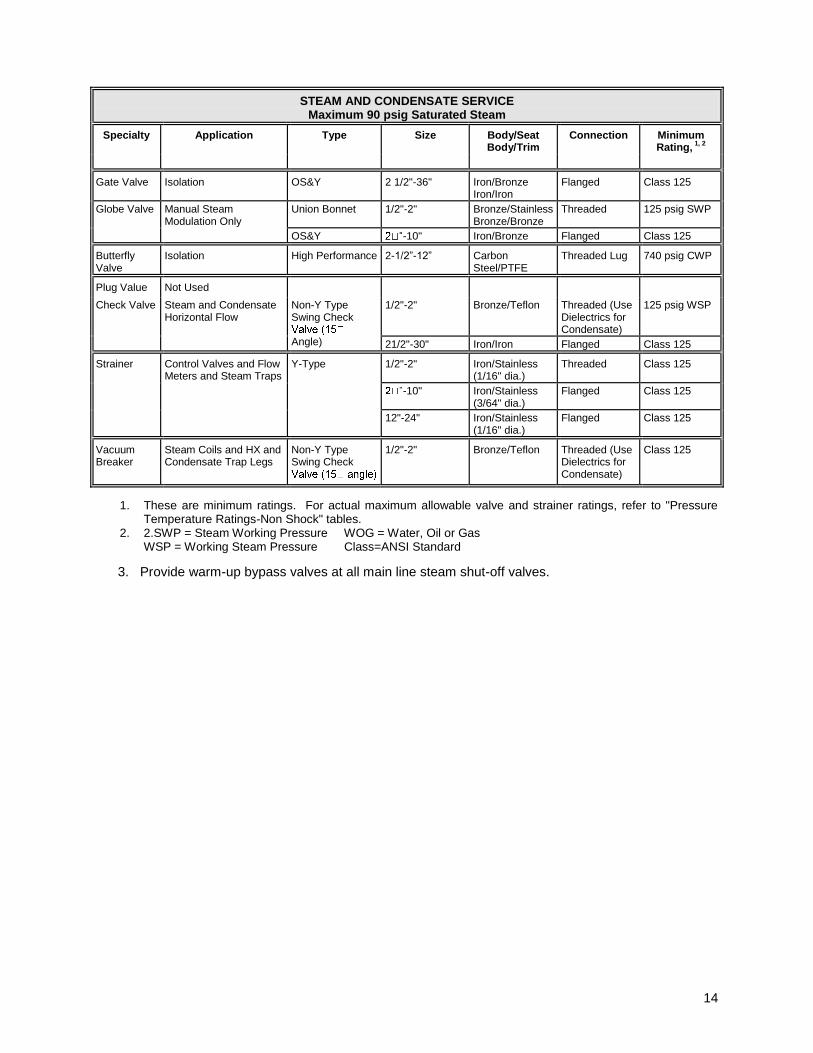
STEAM AND CONDENSATE SERVICE Maximum 90 psig Saturated Steam
Specialty
Application
Type
Size
Body/Seat Body/Trim
Connection
Minimum Rating,
1, 2
Gate Valve
Isolation
OS&Y
2 1/2"-36"
Iron/Bronze Iron/Iron
Flanged
Class 125
Globe Valve
Manual Steam Modulation Only
Union Bonnet
1/2"-2"
Bronze/Stainless Bronze/Bronze
Threaded
125 psig SWP
OS&Y
-10"
Iron/Bronze
Flanged
Class 125
Butterfly Valve
Isolation
High Performance
2-1/2”-12”
Carbon Steel/PTFE
Threaded Lug
740 psig CWP
Plug Value
Not Used
Check Valve
Steam and Condensate Horizontal Flow
Non-Y Type Swing Check
Angle)
1/2"-2"
Bronze/Teflon
Threaded (Use Dielectrics for Condensate)
125 psig WSP
21/2"-30"
Iron/Iron
Flanged
Class 125
Strainer
Control Valves and Flow Meters and Steam Traps
Y-Type
1/2"-2"
Iron/Stainless (1/16" dia.)
Threaded
Class 125
-10"
Iron/Stainless (3/64" dia.)
Flanged
Class 125
12"-24"
Iron/Stainless (1/16" dia.)
Flanged
Class 125
Vacuum Breaker
Steam Coils and HX and Condensate Trap Legs
Non-Y Type Swing Check
1/2"-2"
Bronze/Teflon
Threaded (Use Dielectrics for Condensate)
Class 125
1. These are minimum ratings. For actual maximum allowable valve and strainer ratings, refer to "Pressure Temperature Ratings-Non Shock" tables.
2. 2.SWP = Steam Working Pressure WOG = Water, Oil or Gas WSP = Working Steam Pressure Class=ANSI Standard
3. Provide warm-up bypass valves at all main line steam shut-off valves.

15
STEAM AND CONDENSATE SERVICE Maximum 200 psig Saturated Steam
Specialty
Application
Type
Size
Body/Seat Body/Trim
Connection
Minimum Rating
1, 2
Gate Valve
Isolation
OS&Y
2 1/2"-36"
Iron/Bronze Iron/Iron
Flanged
Class 250
Globe Valve
Manual Steam Modulation Only
Union Bonnet
1/2"-2"
Bronze/Stainless Bronze/Bronze
Threaded
250 psig SWP
OS&Y
2 1/2"-10"
Iron/Bronze
Flanged
Class 250
Butterfly Valve
Isolation
High Performance
2-1/2”-12”
Carbon Steel/PTFE
Threaded Lug
740 psig CWP
Plug Value
Not Used
Check Valve
Steam and Condensate Horizontal Flow
Non-Y Type Swing
Angle)
1/2"-2"
Bronze/Teflon
Threaded (Use Dielectrics for Condensate)
250 psig WSP
2 1/2"-30"
Iron/Iron
Flanged
Class 250
Strainer
Control Valves and Flow Meters and Steam Traps
Y-Type
1/2"-2"
Iron/Stainless (1/16" dia.)
Threaded
Class 250
21/2"-10"
Iron/Stainless (3/64" dia.)
Flanged
Class 250
12"-24"
Iron/Stainless (1/16" dia.)
Flanged
Class 250
Vacuum Breaker
Steam Coils and HX and Condensate Trap Legs
Non-Y Type Swing
angle)
1/2"-2"
Bronze/Teflon
Threaded (Use Dielectrics for Condensate)
Class 250
1. These are minimum ratings. For actual maximum allowable valve and strainer ratings, refer to "Pressure
Temperature Ratings-Non Shock" tables. 2. SWP=Steam Working Pressure WOG=Water, Oil or Gas
WSP = Working Steam Pressure Class=ANSI Standard
3. Provide warm-up bypass valve at all main line shut-off valves
16
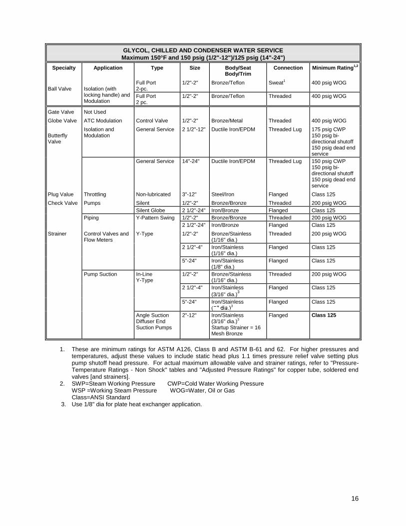
GLYCOL, CHILLED AND CONDENSER WATER SERVICE
Maximum 150 F and 150 psig (1/2"-12")/125 psig (14"-24")
Specialty
Application
Type
Size
Body/Seat Body/Trim
Connection
Minimum Rating
1,2
Ball Valve
Isolation (with locking handle) and Modulation
Full Port 2-pc.
1/2"-2"
Bronze/Teflon
Sweat
1
400 psig WOG
Full Port 2 pc.
1/2"-2"
Bronze/Teflon
Threaded
400 psig WOG
Gate Valve
Not Used
Globe Valve
ATC Modulation
Control Valve
1/2"-2"
Bronze/Metal
Threaded
400 psig WOG
Butterfly Valve
Isolation and Modulation
General Service
2 1/2"-12"
Ductile Iron/EPDM
Threaded Lug
175 psig CWP 150 psig bi-directional shutoff 150 psig dead end service
General Service
14"-24"
Ductile Iron/EPDM
Threaded Lug
150 psig CWP 150 psig bi-directional shutoff 150 psig dead end service
Plug Value
Throttling
Non-lubricated
3"-12"
Steel/Iron
Flanged
Class 125
Check Valve
Pumps
Silent
1/2"-2"
Bronze/Bronze
Threaded
200 psig WOG
Silent Globe 2 1/2"-24"
Iron/Bronze
Flanged
Class 125
Piping Y-Pattern Swing
1/2"-2"
Bronze/Bronze
Threaded
200 psig WOG
2 1/2"-24" Iron/Bronze
Flanged
Class 125
Strainer
Control Valves and Flow Meters
Y-Type
1/2"-2"
Bronze/Stainless (1/16" dia.)
Threaded
200 psig WOG
2 1/2"-4"
Iron/Stainless (1/16" dia.)
Flanged
Class 125
5"-24"
Iron/Stainless (1/8" dia.)
Flanged
Class 125
Pump Suction
In-Line Y-Type
1/2"-2"
Bronze/Stainless (1/16" dia.)
Threaded
200 psig WOG
2 1/2"-4"
Iron/Stainless
(3/16" dia.)3
Flanged
Class 125
5"-24"
Iron/Stainless
3
Flanged
Class 125
Angle Suction Diffuser End Suction Pumps
2"-12"
Iron/Stainless (3/16" dia.)
3
Startup Strainer = 16 Mesh Bronze
Flanged
Class 125
1. These are minimum ratings for ASTM A126, Class B and ASTM B-61 and 62. For higher pressures and temperatures, adjust these values to include static head plus 1.1 times pressure relief valve setting plus pump shutoff head pressure. For actual maximum allowable valve and strainer ratings, refer to "Pressure-Temperature Ratings - Non Shock" tables and "Adjusted Pressure Ratings" for copper tube, soldered end valves [and strainers].
2. SWP=Steam Working Pressure CWP=Cold Water Working Pressure WSP =Working Steam Pressure WOG=Water, Oil or Gas Class=ANSI Standard
3. Use 1/8" dia for plate heat exchanger application.
17
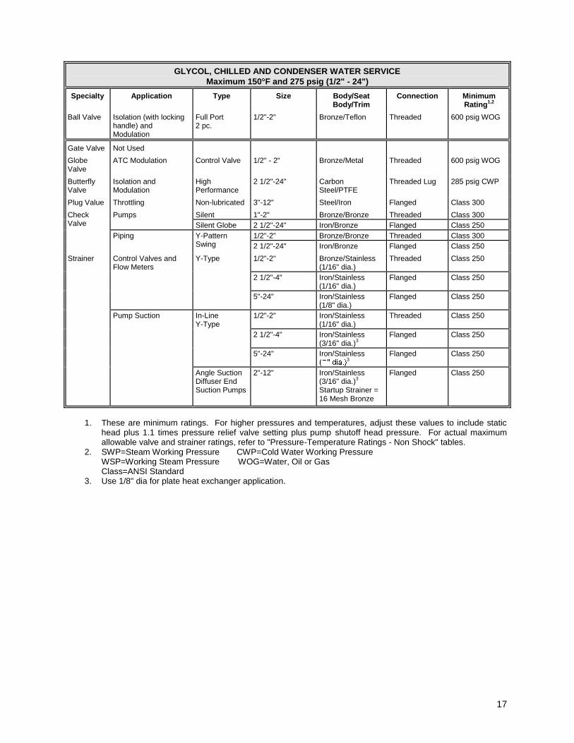
GLYCOL, CHILLED AND CONDENSER WATER SERVICE
Maximum 150 F and 275 psig (1/2" - 24") Specialty
Application
Type
Size
Body/Seat Body/Trim
Connection
Minimum Rating
1,2
Ball Valve
Isolation (with locking handle) and Modulation
Full Port 2 pc.
1/2"-2"
Bronze/Teflon
Threaded
600 psig WOG
Gate Valve
Not Used
Globe Valve
ATC Modulation
Control Valve
1/2" - 2"
Bronze/Metal
Threaded
600 psig WOG
Butterfly Valve
Isolation and Modulation
High Performance
2 1/2"-24"
Carbon Steel/PTFE
Threaded Lug
285 psig CWP
Plug Value
Throttling
Non-lubricated
3"-12"
Steel/Iron
Flanged
Class 300
Check Valve
Pumps
Silent
1"-2"
Bronze/Bronze
Threaded
Class 300
Silent Globe 2 1/2"-24"
Iron/Bronze
Flanged
Class 250
Piping Y-Pattern Swing
1/2"-2"
Bronze/Bronze
Threaded
Class 300
2 1/2"-24" Iron/Bronze
Flanged
Class 250
Strainer
Control Valves and Flow Meters
Y-Type
1/2"-2"
Bronze/Stainless (1/16" dia.)
Threaded
Class 250
2 1/2"-4"
Iron/Stainless (1/16" dia.)
Flanged
Class 250
5"-24"
Iron/Stainless (1/8" dia.)
Flanged
Class 250
Pump Suction
In-Line Y-Type
1/2"-2"
Iron/Stainless (1/16" dia.)
Threaded
Class 250
2 1/2"-4"
Iron/Stainless (3/16" dia.)
3
Flanged
Class 250
5"-24"
Iron/Stainless
3
Flanged
Class 250
Angle Suction Diffuser End Suction Pumps
2"-12"
Iron/Stainless (3/16" dia.)
3
Startup Strainer = 16 Mesh Bronze
Flanged
Class 250
1. These are minimum ratings. For higher pressures and temperatures, adjust these values to include static
head plus 1.1 times pressure relief valve setting plus pump shutoff head pressure. For actual maximum allowable valve and strainer ratings, refer to "Pressure-Temperature Ratings - Non Shock" tables.
2. SWP=Steam Working Pressure CWP=Cold Water Working Pressure WSP=Working Steam Pressure WOG=Water, Oil or Gas Class=ANSI Standard
3. Use 1/8" dia for plate heat exchanger application.

18
HOT WATER SERVICE Maximum 250°F and 175 psig (1/2"-12")/125 psig (14"-24")
Specialty
Application
Type
Size
Body/Seat, Body/Trim
Connection
Minimum Rating1,2
Ball Valve
Isolation (with locking handle) and Modulation
Full Port 2-pc.
1/2"-2"
Bronze/Teflon
Sweat
1
400 psig WOG
Full Port 2 pc.
1/2"-2"
Bronze/Teflon
Threaded
400 psig WOG
Gate Valve
Not Used
Globe Valve
ATC Modulation
Control Valve
1/2"-2"
Bronze/Metal
Threaded
400 psig WOG
Butterfly Valve
Isolation and Modulation
General Service
2 1/2"-12"
Ductile Iron/EPDM
Threaded Lug
200 psig CWP 200 psig bi-directional shutoff 200 psig dead end service
14"-24"
Ductile Iron/EPDM
Threaded Lug
150 psig CWP 150 psig bi-directional shutoff 150 psig dead end service
Plug Value
Throttling
Non-lubricated
3"-12"
Steel/Iron
Flanged
Class 125
Check Valve
Pumps
Silent
1/2"-2"
Bronze/Bronze
Threaded
200 psig WOG
Silent Globe
2 1/2"-24"
Iron/Bronze
Flanged
Class 125
Piping
Y-Pattern Swing
1/2"-2"
Bronze/Bronze
Threaded
200 psig WOG
2 1/2"-24"
Iron/Bronze
Flanged
Class 125
Strainer
Control Valves and Flow Meters
Y-Type
1/2"-2"
Bronze/Stainless (1/16" dia.)
Threaded
200 psig WOG
2 1/2"-4"
Iron/Stainless (1/16" dia.)
Flanged
Class 125
5"-24"
Iron/Stainless (1/8" dia.)
Flanged
Class 125
Pump Suction
In-Line Y-Type
1/2"-2"
Bronze/Stainless (1/16" dia.)
Threaded
200 psig WOG
2 1/2"-4"
Iron/Stainless (3/16" dia.)
3
Flanged
Class 125
5"-24"
Iron/Stainless (1/4" dia.)
3
Flanged
Class 125
Angle Suction Diffuser End Suction Pumps
2"-12"
Iron/Stainless (3/16" dia.)
3
Startup Strainer = 16 Mesh Bronze
Flanged
Class 125
1. These are minimum ratings for ASTM A126, Class B and ASTM B-61 and 62. For higher pressures and temperatures,
adjust these values to include static head plus 1.1 times pressure relief valve setting plus pump shutoff head pressure. For actual maximum allowable valve and strainer ratings, refer to "Pressure-Temperature Ratings - Non Shock" tables and "Adjusted Pressure Ratings" for copper tube, soldered end valves [and strainers].
2. SWP=Steam Working Pressure CWP=Cold Water Working Pressure WSP=Working Steam Pressure WOG=Water, Oil or Gas Class=ANSI Standard
3. Use 1/8" dia for plate heat exchanger application.
19
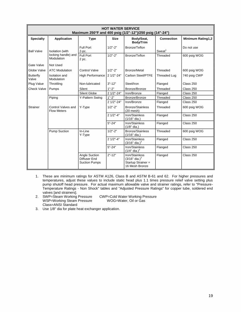
HOT WATER SERVICE Maximum 250°F and 400 psig (1/2"-12")/250 psig (14"-24")
Specialty
Application
Type
Size
Body/Seat, Body/Trim
Connection
Minimum Rating1,2
Ball Valve
Isolation (with locking handle) and Modulation
Full Port 2-pc.
1/2"-2"
Bronze/Teflon
Sweat
1
Do not use
Full Port 2 pc.
1/2"-2"
Bronze/Teflon
Threaded
600 psig WOG
Gate Valve
Not Used
Globe Valve
ATC Modulation
Control Valve
1/2"-2"
Bronze/Metal
Threaded
600 psig WOG
Butterfly Valve
Isolation and Modulation
High Performance
2 1/2"-24"
Carbon Steel/PTFE
Threaded Lug
740 psig CWP
Plug Value
Throttling
Non-lubricated
3"-12"
Steel/Iron
Flanged
Class 250
Check Valve
Pumps
Silent
1"-2"
Bronze/Bronze
Threaded
Class 250
Silent Globe 2 1/2"-24"
Iron/Bronze
Flanged
Class 250
Piping Y-Pattern Swing
1"-2"
Bronze/Bronze
Threaded
Class 250
2 1/2"-24" Iron/Bronze
Flanged
Class 250
Strainer
Control Valves and Flow Meters
Y-Type
1/2"-2"
Bronze/Stainless (20 mesh)
Threaded
600 psig WOG
2 1/2"-4"
Iron/Stainless (1/16" dia.)
Flanged
Class 250
5"-24"
Iron/Stainless (1/8" dia.)
Flanged
Class 250
Pump Suction
In-Line Y-Type
1/2"-2"
Bronze/Stainless (1/16" dia.)
Threaded
600 psig WOG
2 1/2"-4"
Iron/Stainless (3/16" dia.)
3
Flanged
Class 250
5"-24"
Iron/Stainless (1/4" dia.)
3
Flanged
Class 250
Angle Suction Diffuser End Suction Pumps
2"-12"
Iron/Stainless (3/16" dia.)
3
Startup Strainer = 16 Mesh Bronze
Flanged
Class 250
1. These are minimum ratings for ASTM A126, Class B and ASTM B-61 and 62. For higher pressures and
temperatures, adjust these values to include static head plus 1.1 times pressure relief valve setting plus pump shutoff head pressure. For actual maximum allowable valve and strainer ratings, refer to "Pressure-Temperature Ratings - Non Shock" tables and "Adjusted Pressure Ratings" for copper tube, soldered end valves [and strainers].
2. SWP=Steam Working Pressure CWP=Cold Water Working Pressure WSP=Working Steam Pressure WOG=Water, Oil or Gas Class=ANSI Standard
3. Use 1/8" dia for plate heat exchanger application.
20
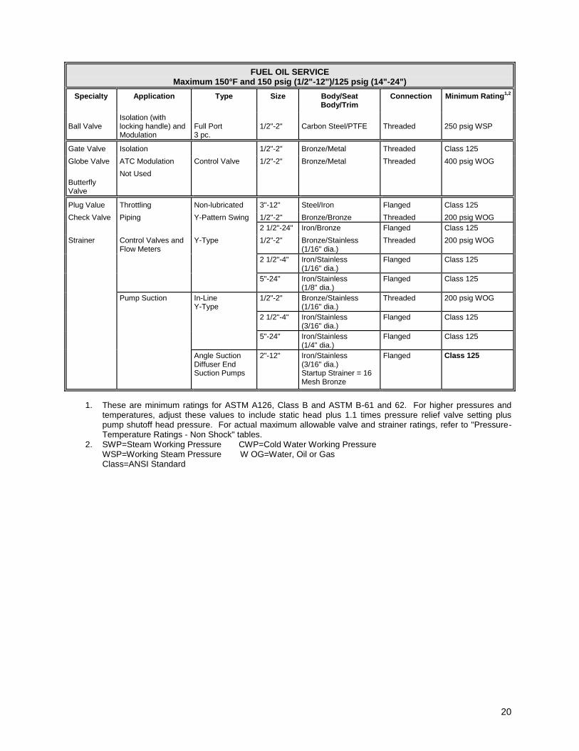
FUEL OIL SERVICE Maximum 150°F and 150 psig (1/2"-12")/125 psig (14"-24")
Specialty
Application
Type
Size
Body/Seat Body/Trim
Connection
Minimum Rating
1,2
Ball Valve
Isolation (with locking handle) and Modulation
Full Port 3 pc.
1/2"-2"
Carbon Steel/PTFE
Threaded
250 psig WSP
Gate Valve
Isolation
1/2"-2"
Bronze/Metal
Threaded
Class 125
Globe Valve
ATC Modulation
Control Valve
1/2"-2"
Bronze/Metal
Threaded
400 psig WOG
Butterfly Valve
Not Used
Plug Value
Throttling
Non-lubricated
3"-12"
Steel/Iron
Flanged
Class 125
Check Valve
Piping
Y-Pattern Swing
1/2"-2"
Bronze/Bronze
Threaded
200 psig WOG
2 1/2"-24" Iron/Bronze
Flanged
Class 125
Strainer
Control Valves and Flow Meters
Y-Type
1/2"-2"
Bronze/Stainless (1/16" dia.)
Threaded
200 psig WOG
2 1/2"-4"
Iron/Stainless (1/16" dia.)
Flanged
Class 125
5"-24"
Iron/Stainless (1/8" dia.)
Flanged
Class 125
Pump Suction
In-Line Y-Type
1/2"-2"
Bronze/Stainless (1/16" dia.)
Threaded
200 psig WOG
2 1/2"-4"
Iron/Stainless (3/16" dia.)
Flanged
Class 125
5"-24"
Iron/Stainless (1/4" dia.)
Flanged
Class 125
Angle Suction Diffuser End Suction Pumps
2"-12"
Iron/Stainless (3/16" dia.) Startup Strainer = 16 Mesh Bronze
Flanged
Class 125
1. These are minimum ratings for ASTM A126, Class B and ASTM B-61 and 62. For higher pressures and temperatures, adjust these values to include static head plus 1.1 times pressure relief valve setting plus pump shutoff head pressure. For actual maximum allowable valve and strainer ratings, refer to "Pressure-Temperature Ratings - Non Shock" tables.
2. SWP=Steam Working Pressure CWP=Cold Water Working Pressure WSP=Working Steam Pressure W OG=Water, Oil or Gas Class=ANSI Standard
21
A. For water service, strainers shall be full size of entering pipe size and have a maximum clean pressure drop of one psid (for steam condensate 1/4 psid). Strainers shall be per tables by Sarco, Mueller, Watts or Armstrong.
B. Pump start up strainer screens shall be used for cleaning and removed afterwards.
C. Provide blow-off valve on each strainer. Blow-off shall be piped to closet drain, where practical and possible.
22
A. Suction diffuser/strainers shall have 200 psi cast iron body and stainless steel sleeve with 5/32" perforations. Units shall include flanged connections, removable gasketed cover and straightening vanes units shall be Bell & Gossett or Armstrong.
B. Provide 16 mesh start-up strainer.
C. Provide blow-off tapping on bottom of unit.
D. Provide full size inlet and outlet.

23
A. Provide bronze Bourdon tube pressure gauges where shown on Drawings and where specified, by U.S. Gauge, Trerice, or Ashcroft, accurate to +1%.
B. Gauges shall have white faces with black-filled engraved lettering. Gauge bodies shall be set in phenolic cases. Provide syphons and shut-off cocks.
C. Gauges shall be easily accessible and easily read. Gauges readable from floor at less than five feet shall have 4-1/2" dials. Other gauges shall have 6" dials. Gauges graduations shall meet limit requirements of normal operation. Gauge shall indicate at mid-scale.
D. Provide separable well V-case thermometers by U.S. Gauge, Trerice, or Ashcroft where shown on Drawings and where specified. Thermometers shall have 9" scale and white face with black-filled engraved letters. Thermometers shall be angular or straight stemmed, as conditions necessitate. Thermometer wells shall be bronze and shall be installed so as to ensure minimum restriction of water flow in pipe.
E. Combination Temperature Pressure Test Plugs
1. Provide, where shown on details, combination pressure temperature test plugs by Peterson Equipment Company "Petes Plug" or Sisco, Inc. "P/T Plugs".
2. Plug shall be 1/4" or 1/2" NPT, constructed of solid brass with a Nordel valve core
1000 psig.
3. Provide extension fitting for each plug suitable for use with 2" maximum pipe insulation.

24
A. General
1. Pipe materials and fitting materials shall be as indicated in Schedule of Pipe and Fitting Materials. Provide dielectric fittings to connect different piping materials.
2. Steel piping 2-1/2" and larger shall be welded; 2" and smaller shall be screwed. Steel piping shall be seamless or electric-resistance welded ASTM A53, Grade B
3. Type L ASTM B88 copper may be used in lieu of threaded steel for hot water , chilled water and condenser water piping 2” and smaller.
4. Use Schedule 80 for welded piping and fittings 2" and smaller.
B. Schedule of Pipe and Fitting Materials
Service
Pipe Material
Weight
For Type of
Joints
Fitting
Material
Pressure Rating psi
swp. or Weight Chilled/hot water
Steel
Schedule 40
Screwed
Iron
Malleable
150
Chilled/hot water
Type L Copper
Soldered
Copper
150
Chilled/hot water
Steel
Schedule 40
Welded
Steel
Schedule 40
Condenser water
Steel
Schedule 40
Screwed
Iron
Malleable
150
Condenser water
Steel
Schedule 40
Welded
Steel
Schedule 40
Heating hot water
Steel
Schedule 40
Screwed
Iron
Malleable
150
Heating hot water
Steel
Schedule 40
Welded
Steel
Schedule 40
Fuel Oil inside bldg.
Steel
Schedule 40
Screwed
Iron
Malleable
150
Fuel Oil underground*
Steel
Schedule 80
Welded
Steel
Schedule 40
Condensate drain
Copper Type L
Soldered
Copper
125
Cold water
Copper Type L
Soldered Copper
Wrought
125
Vents
Galvanized
Steel Schedule 40
Screwed
Iron
Malleable
150
Refrigerant
Copper
Type ACR
Brazed Copper
Wrought
200
Steam (HP)
Steel
Schedule 80
Screwed
Iron
Malleable
300
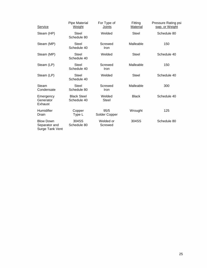
25
Service
Pipe Material
Weight
For Type of
Joints
Fitting
Material
Pressure Rating psi
swp. or Weight Steam (HP)
Steel
Schedule 80
Welded
Steel
Schedule 80
Steam (MP)
Steel
Schedule 40
Screwed
Iron
Malleable
150
Steam (MP)
Steel
Schedule 40
Welded
Steel
Schedule 40
Steam (LP)
Steel
Schedule 40
Screwed
Iron
Malleable
150
Steam (LP)
Steel
Schedule 40
Welded
Steel
Schedule 40
Steam Condensate
Steel
Schedule 80
Screwed
Iron
Malleable
300
Emergency Generator Exhaust
Black Steel Schedule 40
Welded
Steel
Black
Schedule 40
Humidifier Drain
Copper Type L
95/5
Solder Copper
Wrought
125
Blow Down Separator and Surge Tank Vent
304SS
Schedule 80
Welded or Screwed
304SS
Schedule 80

26
A. Provide steam pressure reducing valves shown on Drawings, complying with pressure ranges, capacities and application arrangement. Valves shall be by Leslie only, air actuated type unless approved otherwise by Owner when there is no pneumatic air source available.
B. Valves shall be single-seat, pilot or diaphragm-operated, and shall have cast iron bodies and approved stainless steel seats and trimmings.
C. Valve parts shall be accessible for service without removal from line.
D. Provide three valve bypasses of capacity and range shown on Drawings. Each pressure reducing valve shall be provided with T-type strainer and blow-down valve on strainer.
E. All safety relief valves shall be piped to atmosphere whenever possible. Where safety relief valves cannot be reasonably piped to atmosphere, review the use of automatic safety shut-off valves with YSM.
F. Control air provided to PRVs by a dedicated air compressor (not from ATC compressed air system) must be clean, dry air with a dewpoint less than 15 degrees F when reduced to control operating pressure.

27
A. General Requirements
1. Provide, where shown on drawings, centrifugal pumps, of capacities types and configurations shown on schedules. Acceptable manufacturers shall be Armstrong or Bell and Gossett only.
2. Provide cyclone type abrasive separators to provide clean water flush to seals for all pumps on open systems, and all pumps over 3 HP on closed systems requiring flush. Separator materials and pressure ratings shall be suitable for intended class of service and maximum working pressure of the pump. Provide sheet metal guard to protect separator tubing from damage - do not use poly tubing for separator. Provide shut off cocks with manual valved bypass line to allow separator to be removed for cleaning while seals continue to be flushed.
B. Pump Types and Materials of Construction
1. General:
a. For all types of pumps listed below, bearing frame and pump internals shall be serviceable without disturbing motor or connected piping.
2. Double Suction Split Case Pumps:
a. Double suction pumps shall have horizontally or vertically split casings. Materials of construction shall be for a bronze fitted pump including cast iron casings, bronze shaft sleeves, alloy steel shafts and bronze, enclosed double suction impeller. Provide regreasable ball bearings, casing wear rings, drains and vents, coupling guards and steel baseplate. Stainless steel shaft with no sleeve may be
3. End Suction Pumps
a. End suction pumps shall be based mounted, horizontally coupled with vertically split cases. Materials of construction shall be for a bronze fitted pump including cast iron casings, bronze shaft sleeves, alloy steel shafts and bronze enclosed impellers. Provide regreasable or permanently lubricated ball bearings, casing wear rings, drains and vents, coupling guards and steel baseplate.
4. In Line Pumps
a. In Line pumps shall have bronze fitted construction, including cast iron casings, bronze or copper shaft sleeves, alloy steel shafts and bronze impellers. Bearings shall be either be sleeve type or regreasable ball bearings. Provide casing wear rings, drain and vent connections and flexible coupling or direct drive connection between pump and motor. If the scheduled pump includes ball bearings and a direct drive motor to impeller connection, the submitted pump shall not have sleeve bearings or a flexible coupling between pump and motor. Domestic water applications shall be bronze construction.
5. Circulating Booster Pumps
a. Circulator booster pumps shall be cast iron or bronze body, stainless steel shaft sleeves, stainless steel shafts, glass filled noryl impellers, direct couple motor and permanently lubricated sealed ball bearings.

28
A. Provide 212° F, 2 feet NPSH duplex condensate pump set by ITT Domestic only, as shown on Drawings. Pump set shall consist of:
1. receiver,
2. inlet strainer,
3. water pumps,
4. float switches, and
5. controls and accessories.
B. Provide and wire controls as follows in NEMA 2 panel with hinged door and grounding lug:
1. two combination magnetic starters with three overload relays apiece, with circuit breakers and panel cover interlock;
2. electrical alternator;
3. hand-off-automatic switches with the ability to separately shut off power to and individually lock out each pump.
4. momentary contact test pushbutton;
5. numbered wiring terminal strip;
6. fusible control circuit transformer for each circuit; and,
7. removable mounting plate.
8. Alarm bell.
C. Pump control circuits shall be separate. Alternator shall change pump operating sequence automatically after each cycle and cause simultaneous pump operation upon peak load. Back up pump shall operate automatically upon failure of lead pump or control.
D. All vents from receivers shall be piped to atmosphere.
29
A. Provide traps by Nickolson Armstrong, Gestra or Sarco.
B. Continuous float and thermostatic traps shall have stainless steel floats, bronze fittings and integral thermostatic air bypasses. Bodies and covers shall be of stainless steel or cast iron. Working parts of each trap shall be accessible by removing cover without necessitating disconnection from pipe. All traps to have test tee with valve. Bypasses will not be installed around any trap assembly.
C. Inverted bucket traps shall be cast iron with stainless steel bucket and heat treated chrome steel valve and seat.
D. Thermostatic traps shall have brass bodies and caps with natural brass finish. Bellows, valve head and renewable valve seat shall be stainless steel.
30
1.1 CLOSED LOOP WATER SYSTEMS
A. Provide treatment systems and service for primary closed loop water systems. Do not operate systems without water treatment. Water treatment chemicals shall be by Barclay, Dearborn, Olin or Mogul. Pump and chemical drums shall be by the manufacturers of the chemicals or Liquid Metronics. Dearborn and Liquid Metronics model numbers are used to establish standards of quality.
B. Provide piping necessary for complete systems.
C. Water treatment shall include feeding devices necessary to feed chemical solution into piping system and bring chemical properties of water to within manufacturer's recommended operating limits, in order to minimize corrosion and reduce build-up of slime or other contaminants.
D. Furnish and install a coupon rack capable of accepting six coupons in each chemically treated system. The chemical treatment contractor shall make recommendations as to the use of coupons and shall include the furnishing and analysis of the coupons/system (steel and copper) each month.
E. Closed loop systems (chilled water and heating hot water) shall have water treatment consisting of Dearborn Model Type AV By-Pass Shot Feeder, to feed chemical solution into each piping system. Provide five gallon bypass feeder for systems equal to or less than 1,000 gpm of system flow. Provide ten gallon bypass feeder for systems over 1,000 gpm of system flow. Chemicals shall be Dearborn B-524 (Nitride Corrosion Inhibitor) to maintain control limits at 800-1000 parts per million of sodium nitrite).
F. Make-up glycol/water system for mechanical systems shall consist of:
1. 50 gallon PVC or polyethylene drum with molded fiberglass cover and1” ID copper tubing connection. Drum shall be used to premix glycol/water solution. Provide tapping for level sensor.
2. Two _____ gpm, 120 volt chemical metering pump. Pump shall be capable of varying output by control of stroke and speed. Control shall be by pressure sensor.
3. Provide _____% [by volume] [propylene/ethylene] glycol/water mixture to provide freeze
protection down to _____ F (burst protection to _____ F). Provide inhibitors to level recommended by manufacturer. Glycol shall be Dow Chemical or equivalent by Union Carbide. Use of automotive type anti-freeze is not acceptable.
4. Provide packaged pressure controller panel and associated switches including low level switch. System shall automatically feed glycol solution into piping system as needed.
5. Effluent from glycol system shall meet all applicable codes and regulations.
G. Water treatment for open condenser water system shall consist of:
1. Equipment
a. Provide one Hydac Modu-Max Control System, or equal by Uniloc, Lakewood or Great Lakes consisting of:
1) Control box enclosure, NEMA 12 cabinet, 20 amperes 115V with internal circuit breakers.
2) PH-TDS Conductivity Monitor and Control Module.
3) Flow-through type probe assembly with flow control shut-off; pressurized, prepiped and mounted.
4) Digital display read-out for conductivity and PH controller.
5) Electric contacting water meter.
6) Water meter totalizer.
31
7) Solenoid bleed valve, suitable for outdoor environment.
8) Counter timer control module for inhibitor feed.
9) Biocide programmable module - dual pumps.
10) Containment tank for chemical tanks and drums.
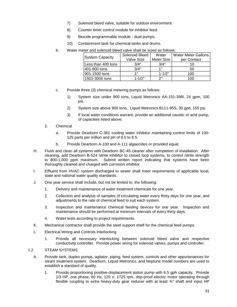
b. Water meter and solenoid bleed valve shall be sized as follows:
System Capacity Solenoid Bleed
Valve Size Water
Meter Size Water Meter Gallons
per Contact
Less than 400 tons 3/4" 3/4" 10
401-900 tons 3/4" 1" 50
901-1500 tons 1" 1-1/2" 100
1501-3000 tons 1-1/2" 2" 100
c. Provide three (3) chemical metering pumps as follows:
1) System size under 900 tons, Liquid Metronics AA-151-398I, 24 gpm, 100 psi.
2) System size above 900 tons, Liquid Metronics B111-95S, 30 gpd, 150 psi.
3) If local water conditions warrant, provide an additional caustic or acid pump, of capacities listed above.
2. Chemical
a. Provide Dearborn C-381 cooling water inhibitor maintaining control limits of 100-125 parts per million and pH of 8.0 to 8.5.
b. Provide Dearborn A-100 and A-111 algaecides or provided equal.
H. Flush and clean all systems with Dearborn BC-45 cleaner after completion of installation. After cleaning, add Dearborn B-524 nitrite inhibitor to closed loop systems, to control nitrite strength to 800-1,000 ppm maximum. Submit written report indicating that systems have been thoroughly cleaned and charged with corrosion inhibitor.
I. Effluent from HVAC system discharged to sewer shall meet requirements of applicable local, state and national water quality standards.
J. One year service shall include, but not be limited to, the following:
1. Delivery and maintenance of water treatment chemicals for one year.
2. Collection and analysis of samples of circulating water every thirty days for one year, and adjustments to the rate of chemical feed to suit each system.
3. Inspection and maintenance chemical feeding devices for one year. Inspection and maintenance should be performed at minimum intervals of every thirty days.
4. Water tests according to project requirements.
K. Mechanical contractor shall provide the steel support shelf for the chemical feed pumps.
L. Electrical Wiring and Controls Interlocking
1. Provide all necessary interlocking between solenoid bleed valve and respective conductivity controller. Provide power wiring for solenoid valves, pumps and controller.
1.2 STEAM SYSTEMS
A. Provide tank, duplex pumps, agitator, piping, feed system, controls and other appurtenances for steam treatment system. Dearborn, Liquid Metronics, and Neptune model numbers are used to establish a standard of quality.
1. Provide proportioning positive-displacement piston pump with 6.5 gph capacity. Provide 1/3 HP, one phase, 60 Hz, 120 V, 1725 rpm, drip-proof electric motor operating through flexible coupling to extra heavy-duty gear reducer with at least ¾" shaft and input HP
32
rating that exceeds motor rating. Piston cross-head shall be bearing bronze and connecting rod bearing shall be uniball with grease fittings. Pump packing shall be spring-loaded and shall be set at factory. Stroke adjustment shall be manual, with micro-screw adjustor.
2. Provide 50 gallon 12 gauge steel chemical feed tank with double-welded seams. Pump platform shall be integral part of tank legs. Provide hinged cover, non-valve gauge glass; cast iron strainer with 60 mesh reinforced PVC suction piping; and 316 stainless steel pressure relief valve with 50-500 psi range, piped to return with clear nylon reinforced PVC tubing. Tank shall be pre-piped to pump suction side. Provide one cu. ft. perforated-metal dissolving basket.
3. Provide Neptune Model A-1 chemical agitator with ¼ HP, one phase, 115 V, 1725 rpm TEFC motor, cast iron clamp, steel coupling, stainless steel shaft and two 14 gauge stainless steel propellers.
4. Provide electrical interlock to start chemical feed pump when boiler feed pump starts.
B. Condensate Receiver - Treatment Feed System
1. Provide one Liquid Metronics A741-955 chemical feed pump.
2. Provide one Liquid Metronics programmable electric water meter model FP-07.
3. Provide one Liquid Metronics 30 gallon polyethylene tank, cover and agitator assembly.
C. Do not operate system without steam treatment.
D. Apply chemical cleaning operation to interior of systems to remove and dissolve foreign substances after completion of installation.
E. Premixed Boiler Treatment Chemicals
1. Provide for alkalinity control - Dearborn B265.
2. Provide for oxygen-scavenging - Dearborn B266.
1.3 DIRECT INJECTED STEAM HUMIDIFICATION SYSTEMS
A. Boiler Water Feed System
1. Provide one Liquid Metronics A741-955 chemical feed pump.
2. Provide one Liquid Metronics programmable electric water meter Model FP-07.
3. Provide one Liquid Metronics 30 gallon polyethylene tank, cover and agitation assembly.
4. Provide containment tank for chemical tanks and drums.
B. Provide all above, piping, wiring and other appurtenances for a complete operating and effective steam treatment system.
C. Provide electric interlock to enable chemical feed pump when boiler feed pump starts.
D. Do not operate system without steam treatment.
E. Flush and clean all systems with Dearborn BC-45 cleaner after installation is complete. Submit a written report indicating that systems have been thoroughly cleaned.
F. Premixed Boiler Treatment Chemicals
1. Provide Dearborn B269 for alkalinity control.
2. Provide Dearborn B273 for oxygen scavenging.
3. Steam treatment chemicals shall be USDA and FDA food grade approved.
G. Dearborn and Liquid Metronics are listed above to establish a minimum standard of quality.

33
A. General
1. Control piping shall be concealed, except in mechanical rooms or areas where other piping is exposed.
2. Concealed lines in concrete or masonry will be non-metallic tubing in conduit.
3. Concealed lines in gypsum wallboard walls or ceilings will be continuous (no fittings) soft copper tubing or non-metallic tubing in conduit.
4. All control air piping above a “drop” ceiling shall be hard drawn or non-metallic tubing in conduit.
5. Exposed lines in mechanical spaces or other unfinished areas will be seamless hard drawn copper tubing or non-metallic tubing enclosed in conduit. Final terminations to control devices can be made with a short piece (12” or less) of non-metallic tubing.
6. Piping shall be a minimum ¼” diameter nominal, Type L for hard drawn copper tubing, type K for “soft” copper tubing, seamless black polyethylene for non-metallic tubing.
7. Control air mains 3/8” and larger shall be hard drawn copper tubing with soldered or brazed joints.
8. Fittings will be soldered or brazed for 3/8” and larger for hard drawn copper tubing. 5/16” tubing and smaller will be soldered or brass compression type fittings on copper tubing; Brass barbed fittings shall be used with non-metallic tubing. Singular barbed fitting made for various sizes of tubing is not acceptable.
9. Transitions from non-metallic tubing to copper shall be made in a junction box or enclosure.
10. Provide a separate high-pressure air supply for control actuators requiring any pressures above 20psig.
11. Control air piping shall be tested at 50psig for a minimum period of 8 hours. Yale’s Project Manager, the Project Superintendent, and Mechanical Design Engineer shall observe, witness, and signoff on the test.

34
A. General
1. Provide where shown on drawings, air cooled water chillers, of capacities as shown on schedules. Acceptable manufacturers providing they meet the requirements of this specification, and the equipment schedules shall be:
a. * Carrier
b. * Trane
c. * York
B. Quality Assurance
1. Chiller shall be rated in accordance with the latest edition of ARI Standard 590.
2. Unit construction shall comply with ANSI B9.1 Safety Code, National Electrical Code and applicable ASME Codes.
3. Unit Cabinet shall be capable of withstanding Federal Test Method Standard No. 141 (method 6061) 500 hour salt spray test.
4. Cooler shall be tested and stamped in accordance with ASME Code for a minimum refrigerant working side pressure of 225 PSIG and a minimum water side pressure of 150 PSIG.
5. Air cooled condenser coils shall be leak tested at minimum 150 PSIG and pressure tested at 425 PSIG.
6. Each chiller shall be factory tested at full and part load conditions-the current draw shall be noted. Results of the test shall be provided to owner. The chiller shall be tested for refrigerant leaks and shipped with a full charge of R134a, R407C or R410A.

35
A. Provide factory-assembled single-zone central station units of type, size, and capacity shown on schedules, with fan section, coil sections, low velocity angle bank filter section and mixing box. Acceptable manufacturers shall be Buffalo, Carrier, Cambridgeport, Trane, or York - provided they meet the requirements of this specification, the performance requirements of the schedule, and fit within the available space for the units (including coil pull).
B. Unit shall be heavy gauge, double wall, steel welded assembly. Enclosure panels shall be 18 gauge steel exterior and 20 gauge steel interior, flush-mounted in unit framework.]
1. Provide manufacturer's standard insulation with maximum K-factor of 0.27,that meets NFPA 90A fire hazard ratings.
2. If cabinet surfaces are not galvanized steel, they shall be phosphatized prior to application of baked enamel primer providing rust resistant paint finish. Units shall be oversprayed with exterior grade enamel after final assembly.
C. Fans shall be centrifugal, Class II construction double inlet, double width. Fans shall be statically and dynamically balanced and tested at rated speed after being installed in factory-assembled section.
1. Fan performance data shall meet latest edition of ARI Standard 430.
2. Bearings shall be self-aligning, grease-lubricated pillow bearings sized to provide minimum average bearing life of 200,000 hours. Lubrication fittings shall be provided on fan.
3. Fan shaft shall be solid, cold finish steel, turned, ground and polished to ensure trouble-free operation and tolerances within recommendations of bearing manufacturer.
4. Fan motors shall be mounted on adjustable base in optional positions.
5. Fan V-belt drive shall be variable pitch. After fans have had final balancing completed, provide fixed sheave of size required for final air balance fan speed
6. Fan belt guards shall be furnished by unit manufacturer for externally mounted motors and shall be made of solid steel with tachometer openings.
7. Provide inlet vanes where required.
8. Belt shall be type AX or BX.
9. Backward inclined or forward curved fans shall be selected at a not to exceed 1200 rpm at normal operating conditions. Where design calls for multiple fans with redundant capacity (i.e. 2 fans @ 100% capacity), RPM may exceed 1200 rpm when operating in service mode (i.e. one out of two fans operating).
D. Coil section shall be double walled, 18 gauge steel with removable panels. Coil section shall be arranged for removal of coil from either end of unit.
1. Hot water coils shall consist of 5/8" or 1/2" OD copper tubing with continuous configurated plate aluminum fins bonded to tubes by hydraulic expansion. Coils shall be tested with 300 lbs. pneumatic pressure under water. Ratings shall meet latest edition ARI Standard 410. Provide 3/4"drain and vent plug at headers.
2. Chilled water coils shall be 5/8" or 1/2" copper tubing with continuous plate aluminum fins bonded to tubes by hydraulic expansion, underwater tested with 300 lbs. pneumatic pressure. Ratings shall meet latest edition of ARI 410. Case shall be stainless steel. Provide 3/4" drain and vent plug at headers.
3. Direct expansion coils shall have aluminum plate fins, 1/2" OD copper tubes and a minimum of two pressure type brass distributors with solder type connections. Intertwined circuits for equal loading shall be provided for full face active or face split operation. Suction line and liquid line connections shall be on the same end. Coils shall
36
under a vacuum of 1000 microns. After dehydration coils will be charged with dry air.
4. Non-freeze steam coils shall have an outer tube diameter of 1" with a 5/8" diameter inner distributing tube. Spiral fins shall be aluminum and headers shall be steel. Working
5. Electric heating coils shall be open wire type 80% nickel 20% chromium resistance coils insulated by floating ceramic bushings and supported in an aluminized or galvanized steel frame. Thermal cutouts for primary and secondary over temperature protection shall be provided to meet UL and NEC requirements. Provide integral control box, containing thermal cutouts, primary and secondary control, back up contactors, sub circuit fusing, airflow switch and a fused control transformer.
E. Provide double wall, stainless steel drain pan with fan and coil sections. Pan shall have a 2" drain connection off the bottom drain at two locations and shall have 1/2" thick, foamed in place, polyurethane insulation with foil vapor barriers.
F. Provide hinged access doors with handles for the fan section and each coil section. Access doors shall extend the full height of the section and shall be capable of allowing access for maintenance, not just inspection. Provide inspection window and marine light per door and section.
37
A. General
1. Provide built-up air handling unit as shown and scheduled on Drawings to supply air to building as part of single duct variable or constant air volume system.
2. Unit Manufacturer shall be responsible for complete design of units, all components, complete shop and field erection of units and all components, operation and performance of units under unit manufacturer's nameplate. The Mechanical Division Contractor shall be responsible for coordination of the delivery and erection of all units in compliance with construction schedule; provision of all necessary external piping, ductwork and miscellaneous connections required to complete the installation of the units in cooperation with and as directed by the manufacturer.
3. The unit manufacturer shall be responsible for provision of fans, either blow-thru or draw-thru design with associated intake, pre and after filter section, steam heating coil, chilled water coil, humidifier section and all other unit and plenum components as specified in this section or other sections of this division and performance characteristics as shown in schedules or on drawings.
4. Unit shall be modular, factory-fabricated for shipping and field assembly or designed for field erection by experienced manufacturer of large custom air handling units that maintains engineering and production staff.
5. Acceptable manufacturers will be Buffalo, Air Enterprise, or Trane Custom, providing they meet the requirements of this section, Yale's design criteria and the performance requirements listed and schedules.
6. Maximum unit operating weight shall be scheduled on drawings.

38
A. SUMMARY
1. This section describes our design intent regarding Air Handing Units with coils. This section is intended as direction to the design team, not the contractor. The design team is instructed to incorporate the concepts discussed below into their construction documents.
B. DESIGN REQUIREMENTS
1. Housing Construction
a. Structural Criteria:
1) The unit shall conform to the structural provisions of the IBC code (with the Connecticut addendum), including, but not limited to, seismic forces, and if an exterior installation, snow load, and lateral wind loads.
b. Base
1) The base shall consist of steel beams or channels for direct bearing support of the steel floor and major components in the casing. It shall be painted with rust-inhibiting primer and rust inhibiting exterior enamel. The base shall have lifting lugs (" minimum) welded to the corers of each rigging module.
c. Floor
1) The floor shall be of 3/16" thick steel safety diamond plate welded to the base. Pans shall be braced and welded at sufficient intervals to support internal equipment components and live loads without sagging or pulsating. Floor shall be painted with rust-inhibiting primer and rust inhibiting exterior enamel. Floor drains shall be 2" type L copper piping, extended to the bottom closure of the base unit. All piping within the base frame shall be insulated.
2) The underside of the floor shall be continuously insulated with two layers of minimum 2" thick rigid fiberglass insulation board (with a density of 6 pounds per cubic foot, maximum K-factor of 0.27) that meets NFPA 90A fire hazard rating.
d. Walls, Partitions and Roof Structure
1) Panel skin thickness, stiffener and frame spacing and thickness, and core density shall be designed to eliminate panel pulsation and to limit the maximum deflection to 1/200 of any span at design pressures.
2) Panels shall be double wall with inner minimum 20 gauge liner and minimum 18 gauge exterior sheet. Inner wall at the fan section shall be perforated sheets of galvanized steel or aluminum. Provide foil liner between insulation and perforated wall to prevent erosion and dirt buildup. Exterior surfaces shall be suitable for weather exposure (including rust inhibiting primer and exterior enamel), and be flush mounted in the unit framework.
3) Minimum panel thickness shall be 4" filled with full thickness of 6 pounds per cubic foot fiberglass insulation board (maximum K-factor of 0.27). Panel sandwich construction shall incorporate a thermal break at all structural members. Panels, including insulation, shall meet the NFPA 90A fire hazard rating requirement. Noise transmission shall be limited so that the noise level does not exceed 65 dB at a distance of 10 ft from the unit at any location.

39
4) Access doors shall be double wall construction and shall meet performance as specified above for panels. Doors shall close tightly against a gasket and shall be airtight. Doors shall be provided for the fan section and on each side of coil (within access sections):
a. Provide in each door one 12"x12" window (double glazed acrylic, tempered or wire glass). Provide airtight runner seals and desiccant in the air space.
b. Doors shall be nominal 70" high and 24" wide. They shall have three tapered latches to force the door against the gasket, and shall have a full height stainless steel piano hinge on the upstream side.
c. Doors on the suction side of the fan shall swing out and doors on the discharge side of the fan shall swing inward. Latches shall operate from both sides of the door.
5) Provide removable gasketed access panel, for removal of the fan, motor and coils. Panels shall be bolted in place. Provide supports for field mounting of piping, control panels and miscellaneous lightweight components.
6) Provide coil section access to allow removal of coils from either side of unit.
7) Panels shall be factory sealed and air tight at corners and seams without visible caulking on casing exterior. Modules assembled in the field with caulking and gasketing shall be air tight, without visible exterior caulking.
8) Roof (exterior units only)
a. The roof shall be without external standing seams and have a minimum 1% pitch, after deflection under snow load. The assembled roof shall be covered with a continuous rubber membrane roofing system with 20 year warranty. Provide underlayment as required by the roof membrane manufacturer. The roof membrane shall be installed by an installer approved by the membrane manufacturer. Roof construction shall provide bearing capacity for suspension of mechanical piping to be field installed. Roof construction shall be 4" thick with insulation as specified above for wall panels.
e. Alternate Cabinet Coating
1) If cabinet surfaces are not galvanized steel, they shall be phosphatized prior to application of baked enamel primer providing rust resistant paint finish. Units shall be oversprayed with exterior grade enamel after final assembly.
f. Drain Pans
1) Coil Drain Pan
a. The main drain pan shall extend beneath the entire cooling coil, including the coil pipe header and return bends in the airway. The pan shall be double walled 16 gauge stainless steel, continuously welded to form a watertight basin with " thick formed-in-place polyurethane insulation with foil vapor barrier. The sides shall be at least 4" high. Provide threaded 2" half couplings welded to the bottom of the pan at two locations for drainage. Run the 2" drain piping from the pan to unit floor drain. The main drain pan shall extend a minimum of 18" downstream of the coils. Provide an intermediate drain pan beneath each stacked cooling coil, extending a minimum of 12" downstream of
stainless steel or copper vertical leader pipes to the main (bottom) drain pan. Provide dielectric fittings between different materials.
2) Fan and Humidifier Drain Pans
40
a. Provide double walled, 16 gauge stainless steel drain pan, beneath both the fan and the humidifier sections, Pans shall be continuously welded to form a watertight basin with " thick formed-in-place polyurethane insulation with foil vapor barrier. Pans sides shall be at least 2" high. Provide threaded 2" half couplings welded to the bottom of the pan at two locations for drainage. Run the 2" piping from the pan to the unit floor drain. Provide dielectric fittings between different materials.
2. Electrical
a. Provide vapor tight marine type fluorescent lighting fixtures in each AHU compartment (and outside the unit on each side, if it is an exterior unit).
b. Provide galvanized rigid steel conduit from the fan motor through the casing wall. Connection to the fan motor shall be liquid tight steel flexible conduit. Rigid conduit shall be fixed to the casing and shall not interfere with operation or access.
c. Provide two empty rigid steel conduit sleeves at each compartment for ATC wiring and air tubing.
d. Provide two weather tight duplex receptacles on the exterior of the unit. Locate appropriately. Provide a separate circuit from the lights.
e. Provide a local disconnect switch for the fan motor, directly outside the fan enclosure.
3. Fans
a. Provide centrifugal fans in applications where the diversified load is minimal (fairly constant speed). Fans shall be AMCA certified and sealed. Fans shall be prime coated with zinc chromate and final coated with two coats of chlorinated rubber based paint to prevent corrosion. Fans shall have centrifugal wheel, Class II construction, double inlet, double width with backward curved hollow airfoil blades. Provide totally enclosed fan cooled motor on an adjustable vibration isolated base. See motor paragraph of YSM Standard Section 15010 for additional requirements).
b. Where the diversified load is great (variable volume systems) and where occupied / unoccupied operational modes are employed, provide centrifugal fans per above with variable frequency drives (VFD) and compatible motors.
c. Alternately, where diversified load is great and where occupied / unoccupied operation is not applicable, provide vaneaxial fans. Fans shall be direct drive, axivane type and AMCA rated for continuous or intermittent use in horizontal, vertical or angular position. Rotor hub and blades shall be cast aluminum. Fan blades shall be individually and manually adjustable through a pitch range as required to achieve design performance. Each blade must be index marked for various pitch settings and be capable of field adjustment. Provide open drip proof motor on an adjustable vibration isolated base.
d. All fans shall be individually statically and dynamically balanced by the manufacturer to within 1 mil double amplitude at 125% of the rated speed
e. Fan performance data shall meet the latest edition of ARI Standard 430.
f. Bearings shall be Dodge Series 2000 self-aligning, grease- lubricated pillow bearings sized to provide a minimum average bearing life of 200,000 hours. Lubrication fittings shall be provided on the fan.
g. Fan shaft shall be solid, cold finish steel, turned, ground and polished to ensure trouble free operation and tolerances within recommendations of bearing manufacturer.
h. Fan shall be selected at a not to exceed 1,200 rpm.

41
i. Sufficient access shall be provided by the fan mounting arrangement within the unit section to allow removal of the rotor of the motor with motor mounted in operating position (without motor removal)
j. Fan V-belt drive shall be variable pitch.
k. Belt shall be type AX or BX.
l. Fan belt guards shall be furnished by unit manufacturer for externally mounted motors and shall be made of solid steel with tachometer openings.
4. Chilled Water Coils and Control Valves
a. Provide completely drainable type chilled water coils. Coils shall be ARI certified, meet latest edition of ARI 410, and the scheduled performance shall be guaranteed by the manufacturer. Coils with inlet and outlets located at the center of headers are not acceptable.
b. At design conditions, the coils shall provide a minimum chilled water temperature rise of 15ºF. Maximum single cooling coil height shall be 42".
c. Chilled water coils shall be 5/8" or 1/2" OD copper tubing with continuous configured plate aluminum fins bonded to tubes by hydraulic expansion. Coils shall be tested with 300 lbs, pneumatic pressure under water. Case and all supports shall be stainless steel. Provide ¾" threaded drain and vent in headers.
d. In locations where chilled water is not available, Direct expansion coils shall have aluminum plate fins, 1/2" OD copper tubing and a minimum of two pressure type brass distributors with solid type connections. Intertwined circuits for equal loading shall be provided for full face active or face split operation. Suction line and liquid line connections shall be on the same end. Coils shall be tested with 300 lbs. pneumatic pressure under water, then hydrated in a 250ºF oven under a vacuum of 1,000 microns. After dehydration, coils will be charges with dry air.
e. Without exception, two way control valves will be used for chilled water coils. The valve will be selected by the designer, not the contractor. Equal percentage valves will be selected to approximate a linear relationship between valve stem position and coil output (not water flow). The Cv of the valve will be determined by the ACTUAL pressure drop across the valve (not be based on the percent of system pressure drop).
f. Circuit setters are required in the return piping of the coil.
g. Isolation valves shall be installed before and after all coils. (Including all coil sections).
5. Preheat Coils and Valves
a. Non-freeze steam preheat coils shall be used wherever steam is available in sufficient quantities. Where steam is not available, hot water preheat coils shall be used. Hot water coils and valves should be designed to the same criteria as chilled water coils and valves (refer to section d. above).
b. Non freeze steam coils shall have an outer tube diameter of 1" with a 5/8" diameter inner distributing tube. Spiral fins shall be aluminum and headers shall be steel. Working pressure shall be 175 psig at 400ºF. Minimum face velocity at design airflow shall be 800 fpm.
c. In areas where steam is not available, hot water coils shall consist of 5/8" or 1/2" OD copper tubing with continuous plate aluminum fins bonded to tubes by hydraulic expansion. Coils shall be tested with 300 lbs, pneumatic pressure under water. Ratings shall meet latest edition ARI standard 410. Provide ¾" threaded drain and vent in headers. Minimum face velocity at design airflow shall be 800 fpm.
d. In areas where steam and hot water are not available, electric heating coils shall be open wire type, 80% nickel, 20% chromium resistance coils insulated by

42
floating ceramic bushings and supported in an aluminized or galvanized steel frame. Thermal cutouts for primary and secondary over-temperature protection shall be provided to meet UL and NEC requirements. Provide integral control box, containing thermal cutouts, primary and secondary control, back-up contactors, sub circuit fusing, airflow switch and a fused control transformer. Electric coils shall be provided with SCR type controls or adequate stages to prevent hunting. Minimum staging shall be based on a maximum of 10ºF temperature rise per stage.
e. Without exception, two way control valves will be used for preheat coils. The valve will be selected by design engineer, not the contractor. Equal percentage valves will be selected to approximate a linear relationship between valve stem position and coil output (not flow). The Cv of the valve will be determined by the ACTUAL pressure drop across the valve (not be based on percent of system pressure drop)
f. Provide multiple section preheat coils with individual control valves for each section. Independent averaging sensors shall be used to control each coil section.
g. Freezestat protection shall be serpentine type located on the face of the coil.
6. Primary Air Filters (Pre-Filters)
a. Primary Filters shall be UL class 2, 2" thick pleated fabric filter. Efficiency shall be MERV 7 (25 to 30%) as measured by ASHRAE test standard 52.1-1992. Initial pressure drop shall be less than 0.28" at a velocity of 500 fpm. Filters shall be designed to operate up to 500 fpm.
7. Secondary Filter (Final)
a. The filter efficiency shall be MERV 13 (80 to 85%) as measured by ASHRAE test standard 52-76. It shall have an average arrestance of 99% on that standard. Filters shall be designed to operate up to 500 fpm. Filters shall be 24" deep bag filters if space allows. If 24" bag filters will not fit, use 12" cartridge type filters. Filters for Critical Research areas shall be MERV 14 (90-95%).
8. Control and Smoke Dampers
a. Leakage characteristics shall be based upon test procedures per AMCA standard 500. Air leakage shall be limited to 6 cfm per square foot at 4" WG differential pressure.
9. Steam Humidifiers
a. Humidifier shall be steam type with fully modulating direct acting normally closed control valve, stainless steel distribution manifold(s), and pneumatic modulating operator, strainer and traps. Refer to Section 15755 for additional requirements.
10. Motors
a. Refer to section 15010 for specific electric motor requirements. All fan motors shall be premium efficiency type. They shall conform to NEMA Standard MG-1-12.53a and have their efficiencies determined in accordance with IEEE Standard 112, method B. Refer to YSM Standard Section 15010 Motors for additional requirements
C. ACCEPTABLE MANUFACTURERS
1. Acceptable manufacturers shall be Air Enterprises, Buffalo, Governair or Trane Custom, provided they meet the requirements of this specification, the performance requirements of the design and fit within the available space for the unit (including coil pull).
2. The above specification is based on built-up air handling units only. Where commercial units are required due to budget constraints on non-critical applications, construction must be revised to available options. Critical facilities (labs & animals) shall use only built-up units. Examples of revisions required include consideration of 2" wall units, standard access doors, elimination of view windows in doors, etc.... Acceptable manufacturers of standard units are Carrier, Trane and York.

43
A. Provide air cooled air conditioning package of size, type, and capacity shown and scheduled on Drawings, by Carrier or Trane.
B. Wall cabinet shall be heavy gauge galvanized steel with baked enamel finish over prime coat. Provide extruded aluminum alloy horizontal line grill with anodized finish.
C. Chassis shall contain condensing coil, hermetic compressor, evaporator coil, condenser fan, two heavy duty motors, heater element, double-inlet centrifugal blowers, ventilation intake and controls, factory-assembled, wired and tested. Unit shall meet NEC Standards and shall be UL-listed.
44
A. Provide complete DX system for central station air conditioning units of types, sizes and capacities shown on schedules. System shall consist of matching air cooled condensing units, compressors, piping, controls, wiring and other accessories and appurtenances necessary to provide fully automatically functioning system. Systems shall use R407C or R410A refrigerant.
B. Condenser coil shall be aluminum plate fins, mechanically bonded to seamless copper tubes, circuited for subcooling. Provide propeller fans arranged for vertical discharge. Condenser fan motors shall have inherent protection and shall be permanently-lubricated and resiliently- mounted. Fans shall have safety guards. Provide controls for cycling fans.
C. Compressors shall be serviceable hermetic with external spring isolators and automatically reversible oil pump.
1. Compressor shall unload in response to suction pressure in steps for partial load operation. Compressor shall be separated from condenser fans and coil.
2. Multiple compressor units shall have stop-start fans and coils. Compressor motors shall have part-winding start.
D. Provide factory-wired controls in separate enclosure. Safety devices shall consist of high and low pressure switching and compressor overload devices. Wiring shall incorporate positive acting timer to prevent short cycling of compressor if power is interrupted. Time shall prevent compressor from restarting for approximately 5 minutes after shutoff. Units shall have transformer control circuit.
E. Casing shall be galvanized steel finished with baked enamel. Provide service access panel.
F. Provide openings for power and refrigerant connections.
G. ambient operation shall be accomplished by varying the speed of condenser fan based on sensing of head pressure in refrigerant liquid line, by modulating damper in condenser fan discharge based on refrigerant head pressure sensing, or by flooding the condenser coil with liquid refrigerant to maintain the desired condenser pressure. Low ambient systems which cycle fans or modulate dampers based on ambient temperature exclusively, are unacceptable. Provide time delay relay for timed bypass of the low pressure switch or other means to start condensing unit at 0 F without nuisance safety trip units. Any field installation and control wiring of low ambient operation components shall be performed under the work of the mechanical section according to equipment manufacturers instructions. If condensing unit does not come with hot gas bypass prepiped, provide under the work of the mechanical section all components necessary for hot gas bypass operation. Hot gas system shall be piped in strict accordance with recommendations of condensing unit manufacturer. Submit with shop drawings showing refrigerant piping, hot gas piping layout including bypass pipe sizes and connection locations, hot gas bypass valve and solenoid valves manufacturers and model numbers, sensing capillary bulb locations, control wiring of solenoid and details of any other components. Adjust hot gas bypass in field, as required, to maintain proper system operation.
H. Provide refrigerant piping between air-cooled condensing unit and AC unit. Provide necessary auxiliaries and appurtenances, such as strainer, sight glass, oil trap, scale trap, and other devices, to make system complete and operable under fully automatic control. Refrigeration piping shall be ACR copper tubing made up with wrought copperfittings using silver solder, installed with nitrogen charge while soldering; of sizes as recommended by manufacturer of air conditioning unit and matching air-cooled unit. Piping shall meet requirements of Piping and Valves Paragraphs of this Section.
I. Provide back-seating globe stop valve, winged and sealed. Cap valves 1" and under shall be diaphragm packing.

45
A. Provide water source heat pump conditioner where shown on Drawings with capacities and characteristics as listed in Schedule, arranged for 100% recirculated air. Acceptable manufacturers shall be Climatemaster, Mammoth, McQuay or Trane.
B. Provide chassis for floor-mounting, with integral control box mounted in chassis, and room cabinet (color as selected by Architect) with 4" high black toe-step base.
C. Provide chassis suitable for fastening to wall at two points with removable fan deck with PSC motor, motor disconnect and refrigerant circuit and glass fiber filter mounted horizontally and removable without removal of room cabinet.
1. Supply and return connections shall be 5/8" O.D. copper tube.
2. Piping connections shall be right or left hand as shown on Drawings.
3. Provide 2” x 4” electric junction box for field power connections at same end as piping connections. Tape paper board cover over coil and drain pan assembly.
D. Provide sealed refrigerant circuit with hermetic motor-compressor, air-to-refrigerant finned tube coil, capillary expansion tube, pilot- operated refrigerant reversing valve, water-to- refrigerant coaxial tube exchanger and high pressure and low temperature safety cutouts.
E. Refrigerant shall be either R-407C or R-410A.
46
A. Provide ceiling-mounted heat pumps with horizontal air inlet, and air discharge. Acceptable manufacturers shall be Climatemaster, Mammoth, McQuay or Trane. Casing shall have corner and panel construction with 14-gauge galvanized steel base pan. Provide access panels lined internally with acoustic fibrous glass for electrical access on one side and blower and motor access on opposite side. Coat internal parts subject to water exposure with baked-on thermo-setting plastic.
B. Service panels on the bottom of ceiling mounted equipment shall be hinged or provided with safety chains to prevent them from falling when opened.
C. Corners shall have threaded nut and pin locator hole for hanger bracket assembly. Provide hanger bracket assemblies, with heavy steel hanger bracket, integral vibration isolator, cap screw and plated isolator washer. Hanger bracket assemblies shall accommodate 3/8" diameter hanger rod.
D. Provide sealed refrigerant circuit with hermetic motor-compressor with internally fused capacitor (none on three-phase), air-to-refrigerant finned tube coil, capillary expansion tube, pilot-operated refrigerant reversing valve, water-to-refrigerant coaxial tube exchanger and high pressure and low temperature safety cutouts on refrigerant circuit. Wire cutouts through factory-installed lock-out to relay to hold conditioner off regardless of wall thermostat position until reset electrically at circuit breaker panel.
E. Provide (direct-drive) (belted-drive) centrifugal blower. Motor speed shall not exceed 1200 rpm synchronous speed. Motor shall have two-year lubrication capacity and shall be factory-lubricated. Provide external-access oiler tubes.
F. Conditioner shall have 1" thick fibrous glass air filter in four-sided filter frame at air inlet with one side removed in field for filter access. Locate piping and electrical connections to eliminate interference with removal and replacement of filter.
G. Refrigerant shall be either R-407C or R-410A.
47
1.1 STEAM HUMIDIFIERS (PACKAGED DISPERSION PANEL)
A. Provide, where indicated on the drawings, packaged steam injection type humidifier panel(s) as manufactured by DRI-STEEM only.
B. Each panel shall consist of a steam supply header/separator, a condensate collection header and a bank of closely spaced steam dispersion tubes spanning the distance between the two headers. The humidifier shall provide absorption characteristics that preclude water accumulation on any in-duct surfaces within 24” downstream of the humidifier tube panel while maintaining conditions of 90% (maximum) relative humidity at a minimum temperature of 50
oF
in the duct air stream. Air pressure loss across humidifier panel shall not exceed 0.1” W.C. at a duct velocity of 1000 fpm.
1. Each packaged humidifier panel assembly of tubes and headers shall be contained within a stainless steel casing to allow convenient duct mounting or to facilitate the stacking of and/or the end-to-end mounting of multiple panels in ducts or air handler casings.
2. All tubes and headers shall be of 304 stainless steel and joints shall be welded. The humidifier shall be furnished with manufacturer selected steam valve, steam strainer and F&T steam traps, all shipped loose for installation on the job. Humidifier shall receive steam at supply pressure and discharge at atmospheric pressure. Valve and seat shall be stainless steel. Pneumatic modulating actuator will actuate the valve to provide modified linear response characteristics over the entire stroke of the valve.
3. For duct mounted humidifiers, provide stainless steel drain pan in duct, 5 feet before and after humidifier. Provide access door in side of duct and 1" drain connection.
4. Where condensate is to be returned to a pressurized condensate return line, provide Ultra-sorb XV dispersion tube.
1.2 STEAM HUMIDIFIERS WITH PNEUMATIC CONTROL
A. Provide steam separator humidifiers with pneumatic modulating control providing full separation ahead of integral steam-jacketed control valve that discharges through internal steam-jacketed drying chamber, silencing chamber and steam jacketed distribution manifold.
B. Humidifier shall receive steam at supply pressure and discharge at atmospheric pressure. Provide inlet strainer and float and thermostatic steam trap.
C. Separating chamber shall disengage and remove water droplets and particulate matter larger than 3 microns when humidifier operates at maximum capacity.
D. Provide integral, parabolic, steam-jacketed plug metering valve at supply pressure and temperature. Valve shall have high rangeabilities to achieve full, accurate modulation of steam flow over entire valve stroke.
E. Internal drying chamber shall receive steam at essentially atmospheric pressure and be jacketed by steam at supply pressure.
F. Silencing chamber shall be steam jacketed and shall use stainless steel silencing medium.
G. Distribution manifolds shall provide uniform distribution over entire length and shall be jacketed by steam at supply pressure. Provide full length stainless steel internal silencing screen.
H. Provide interlocked temperature switch to prevent humidifier from operating before start-up condensate is drained.
I. Humidifier shall be by Dri-Steem ONLY
J. Provide aluminum pan in duct 3 ft. before and after humidifier. Provide access door in side of duct.
48
1.3 ELECTRIC STEAM HUMIDIFIER
A. Provide Armstrong Series EHU-500, Dri-Steem only (vapor steam) self-contained, electronically-controlled steam humidifier. House internal components in steel cabinet with key-locked access door. Humidifier shall be UL- and CSA-listed.
B. Capacity shall be field-adjustable to modulate from 0 to 100% with gradual increase in amperage to avoid current surges.
C. Provide steam generator.
D. Power shall be three-phase with field-adjustable electrodes for efficient operation in varying water conditions. Provide electrical terminals for controlling humidistat, duct high-limit humidistat and interlock switch to fan motor sail switch in duct or both.
E. Provide automatic water drain cycle to evacuate minerals and particles left in suspension in generator. Provide one drain valve for each generator. Automatic drain cycle shall be field-adjustable for drain duration range of 2 to 128 seconds and drain interval range of .25 to 16 hours. Electronic circuit shall provide automatic protection from excessive electrode current and high water overflow. Provide electronic timer.
F. Provide for air gap in humidifier fill water line to prevent back siphonage of contaminated water into water supply.
G. Provide stainless steel dispersion tube sized to span widest dimension of duct to ensure uniform steam distribution over entire tube length.
H. Provide 1-½" diameter reinforced rubber steam hose to convey steam from generator to dispersion tube and drain condensate back to generator.
I. Provide aluminum pan in duct 3 ft. before and after humidifier. Provide access door in side of duct.
J. Provide solid-state electronic humidistat for fully modulating steam flow and high limit humidistat.
K. Humidifiers, which de-energize their heating elements during the period that they refill with water, shall not be acceptable. Humidification capacity must be maintained throughout any fill cycle.
L. Provide [built on] [remote] blower pack by same manufacturer as humidifier. Blower pack shall be UL listed and shall have an air proving switch to prevent humidifier operation if blower is not operating. If a power connection, separate from the humidifier, if required, it shall be provided under the work of the mechanical section, by this contractor.
M. Provide either probe or float type water level control. Where water conductivity is not suitable for probe type control use float type level control.
1.4 HUMIDIFIERS (SELF-CONTAINED)
A. Provide centrifugal humidifiers of scheduled capacity by Bahnson, Standard Engineering or Nortec (Defensor).
B. Humidifiers shall have heavy-duty totally enclosed, sealed-ball-bearing motor with internal overload protection.
C. Humidifier component materials shall be non-corrosible.
D. Provide stainless steel filter screen and filter paper over screen.
E. Furnish aspirated cabinet humidity controls in quantity and location shown on Drawings. Coordinate with Automatic Temperature Control Paragraph.
F. Provide either probe or float type water level control. Where water conductivity is not suitable for probe type control use float type level control
49
15761 HEAT RECOVERY (GLYCOL/WATER) COILS
A. Provide heat recovery (glycol/water) coil removable from connection side of casing and supported in tracks over entire length of coil. Coils shall be aluminum corrugated plate fins on 5/8" OD staggered copper tubes. Fins shall have belled collars and shall be bonded to tubes by mechanical expansion.
B. Provide stainless steel casings and steel headers.
C. Certify suitability for 250 psig working pressure at 200° F.
D. Test at air pressure of 150 psig submerged in water. Coils shall be drainable and shall have non-trapping circuits.
E. Coils shall meet requirements of the latest edition of ARI 410. Provide corrosion resistant coating suitable for airstream. Acceptable manufacturers shall be Aerofin or Heat Craft.
F. Provide 2” thick, Merv 7 (25-30%) pre-filter before inlet to coil.
G. Provide stainless steel drain pan under heat recovery coil piped to drain.
50
A. Provide (hot water) (steam) cabinet heaters where shown on Drawings and on schedules. Cabinet heaters shall be factory assembled for field installation. Cabinet heaters shall be by Trane or McQuay.
B. Coils shall have seamless copper serpentine tubes and aluminum or copper fins bonded to tubes. Coils shall be tested at 200 psig air pressure without leaks.
C. Provide cabinet heaters with tamper-proof front panel screws and key latches.
D. Filters shall be disposable.
E. Provide factory-mounted disconnect switch.
F. Each unit shall be valved separately and have union connections to facilitate easy removal.
51
A. Provide air-cooled condenser of size and capacity shown on Drawing schedule, by Carrier, Trane or York.
B. Units shall consist of coils, with integral subcooling, and casing with stand. Coil shall be aluminum plate fins on mechanically-expanded copper tubes. Coils shall be cleaned, dehydrated, sealed, leak tested at 150 psig, and pressure tested at 420 psig.
C. Fans shall be direct-drive, propeller, protected with guards. Condensers shall have two 3-phase motors and one permanent split capacitor motor for use with accessory speed control suitable for reduced voltage starting. Motors shall be prelubricated, with built-in overload protection.
D. Fan shaft shall be corrosion protected. Fan blades shall have irradiated or aluminum finish. Magnetic contactor shall be field supplied. Provide magnetic contactors in accessory fan cycling control package to cycle fans in response to outdoor ambient temperature.
E. Casing shall have baked enamel finish. Access panels shall be provided for electrical connections.
F. Head pressure control shall be accomplished by fan cycling.

52
A. Provide factory fabricated fan coil units of type and capacity indicated by Carrier, McQuay, Enviro-Tec, Trane or York.
B. Fan coil unit shall comprise:
1. Galvanized steel cabinet with baked enamel finish liner shall be covered with UL 25/50 mylar or foil.
2. Service panels on the bottom of ceiling mounted equipment which shall be hinged or provided with safety chains to prevent them from falling when opened.
3. Centrifugal forward curved galvanized steel fans, statically and dynamically balanced, permanently lubricated or ball bearing shaft bearings.
4. Water coil: with aluminum fins mechanically bonded to staggered 1/2" O.D. copper tubes and leak tested at air pressure of 350 psig.
C. Provide manual valves to isolate each fan coil.

53
A. Provide (hot water) (steam) unit heaters of (horizontal) (vertical) discharge as shown on Drawings and on schedules. Unit heaters shall be factory assembled for field installation, by McQuay or Trane.
1. Coil shall have seamless copper serpentine tubes and aluminum or soldered copper fins bonded to tubes. Coils shall be tested at 300 psig air pressure without leaks.
B. Hangers and supports shall incorporate vibration and noise isolators. Motor and fan shall be separated from heater by resilient vibration isolators. OSHA-approved fan guards shall be provided on heaters.
C. Each unit shall be valved separately and have unions to facilitate easy removal.

54
A. Provide electric unit heaters of horizontal discharge type, by Q Mark, Markel, Brasch or Trane, as shown on Drawings and on schedules.

55
A. Provide electric cabinet heaters where shown on Drawings and on schedules. Cabinet heaters shall be factory assembled for field installation. Cabinets shall be 16 gauge steel with corrosion-resistant finish. Cabinet heaters shall be by Q Mark, Brasch or Trane.
B. Heating coils shall be single terminal end long life electric fin tube with brazed helical coiled fins.
C. Provide cabinet heaters with automatic reset thermal overload protector.
D. Provide integral thermostats.
E. Filters shall be disposable.
56
A. Reference Standards
1. Material, construction and installation shall meet requirements of most recent editions of the following standards and references, except for more stringent requirements specified or shown on Drawings:
Standard
As Applicable To
SMACNA HVAC Duct Construction Standards (Metal and Flexible)
Sheet Metal Ductwork; Duct Liners; Adhesives; Fasteners; Flexible Ductwork.
SMACNA HVAC Air Duct Leakage Test Manual
Duct Leakage Testing (medium pressure only)
Industrial Ventilation and SMACNA Industrial Duct Construction
Dust Collection System; Canopy Hoods; positive and negative pressure ductwork above 10” w.g.
NFPA 90A
Fire Dampers; Fire Resistance Standards for Ducts and Liners
NFPA 96
Kitchen Hood Exhaust Ductwork
NFPA 45
Laboratories using chemicals
SMACNA Guidelines for Welding Sheet Metal
Welded Galvanized, Black Iron and Stainless Steel Ductwork
2. Ductwork shall have pressure-velocity classifications as follows:
DUCT CONSTRUCTION CLASS
STATIC PRESSURE RATING
PRESSURE
SMACNA SEAL CLASS
SMACNA LEAKAGE CLASS
VELOCITY
10"
10"
Pos.*
A
3
2000 fpm or greater
6"
6"
Pos.*
A
3
2000 fpm or greater
4"
4"
Pos.*
A
3
4000 fpm or less
3"
3"
Pos. or Neg.**
A
3
4000 fpm or less
2"
2"
Pos. or Neg.
A
6
2500 fpm or less
*For positive pressures above 10” w.g. and negative pressures more than -10” w.g., refer to SMACNA Round and Rectangular Industrial Duct Construction Standards for joint and intermediate reinforcement requirements.
57
3. Exhaust Stacks
a. All bracing shall be external to stacks (internal bracing will be allowed for shipping and erection as long as it is removed after erection). Stacks shall be (stainless steel) (steel with epoxy paint). Color shall be selected by Owner.
4. Materials
a. Sheet metal ducts shall be constructed of hot-dipped galvanized sheet metal with G90 Commercial coating according to ASTM 527 unless specified otherwise.
b. Stainless steel (SS) ductwork shall be 316/No. 4 finish for exposed duct, 304/No. 1 finish for concealed ducts.
c. Aluminum ductwork shall be Alclad 3003-1414 or alloy 5052-H32, of thickness required by the SMACNA duct construction standards.
d. In welded cases for all metal ductwork, the filler rod material shall equal or exceed the base metal properties.
e. Internal duct lining shall not be used with the exception of sound attenuation for exhaust terminal units or valves.

58
A. Provide AMCA-rated and sealed all steel belted vent sets in locations and of capacities shown on Drawings, by Greenheck, Penn, Cook, Peerless, Barry or Buffalo.
B. Provide venturi inlet cone, backward-inclined wheel, adjustable-pitch V-belt drive rated for 165% of driven horsepower, open drip-proof motor, adjustable sheaves and "swing-out" or clamshell design with permanently lubricated ball bearings. Belts shall be type AX or BX.
C. Provide phosphatized, enameled housings with inlet and outlet guards, bolted access door, drains, weather hoods, backdraft dampers and disconnect switches.
D. Backward inclined or forward curved fans shall be selected at a not to exceed 1200 rpm at normal operating conditions. Where design calls for multiple fans with redundant capacity (i.e. 2 fans @ 100% capacity), RPM may exceed 1200 rpm when operating in service mode (i.e. one out of two fans operating).

59
A. Provide Strobic Air Corp, Greenheck or M.K.Plastics model for Owner's acceptance or rejection for mixed flow, high plume roof mounted exhaust fans.
B. Direct drive with impeller mounted directly to the motor shaft. Motor shall be isolated from the primary exhaust air stream and shall be visible and accessible from the fan exterior for inspection and service. Backward inclined or forward curved fans shall be selected at a not to exceed 1200 rpm at normal operating conditions. Where design calls for multiple fans with redundant capacity (i.e. 2 fans @ 100% capacity), RPM may exceed 1200 rpm when operating in service mode (i.e. one out of two fans operating).
C. Manufacturers providing inline or belt drive fans shall include the following items:
1. 2” deflection all directionally restrained, seismic rated spring vibration isolators, Mason Industries Model SLR-S. Isolators must be installed on each individual fan with a minimum of four per fan. Isolation of the fan mixing plenum is not acceptable.
2. 1/4” thick neoprene inlet and outlet flexible connectors on the fan inlet and discharge.
3. A welded structural steel mounting frame fabricated of 2”x2”x3/8” steel angle designed to allow the fans to be suspended from the framework and separated from the plenum and the building structure with the spring isolators and the flexible connectors.
4. Modular welded structural steel roof base with 8” perimeter channels and 6” and 4” cross members and gussets to support discharge sound attenuators. Top plate to be 3/16” plate steel. Provide 3" x 3" perimeter angle on inside face of perimeter channel to make weathertight seal at roof curb. The structural steel base and sound attenuators shall be rated for a 120 mph windload without supplemental structural supports or guide wires. The overall height of the assembly with the support structure and discharge attenuators shall not exceed the dimensions shown on the plans.
5. Silencer and architectural screen enclosure. The framework and silencer shall be rated for a 120 mph windload without supplemental structural supports or guide wires.
6. The overall height and the footprint of the assembly with the plenum, fans, support structure and discharge attenuators shall not exceed the dimensions and weight shown on the plans.
D. Mixed flow impeller with combination axial-backward curved blades. Welded steel construction stationary discharge guide vane section. Non-stall and non-overloading characteristic with stable operation at any point on the fan curve. Spark resistant construction per AMCA "C".
E. Fan dynamic balance not to exceed 0.50 mil, peak to peak, at the blade pass area when operating at fan frequency. Isolation shall be limited to rubber-in-shear pad type isolator.
F. Twin FRP discharge nozzle with passive third central stack capable of generating an aspiration effect. Steel entrainment windband to provide secondary induction of outside air. Induction shall take place downstream of the fan impeller. Overall total mass discharge up to 270% of design flow rate. Manufacturer to publish discharge volume of all fans at specified primary exhaust flow.
G. Fans shall be modular construction and capable of being assembled on the roof.
H. PTFE gaskets shall be provided at all companion flanged joints.
I. Fasteners shall be a combination of 316 stainless steel and monel to prevent binding.
J. Bolted access door for impeller inspection on fan sizes BS-005 and larger.
K. Internal drain system to prevent rain water from entering building duct systems.
L. Electric motors shall be TEFC Mill and Chemical Duty, 1.15 service factory. Motors 25 hp and below shall be supplied with sealed bearings.
M. A NEMA 3R non-fused disconnect switch shall be provided, mounted and wired to the motor.

60
N. Coatings: All steel and aluminum surfaces shall be prepared for coating by lasting of chemical etching. Coating will be:
O. Corrosion Resistant Epoxy Phenolic, Amerlock 400 Epoxy Intermediate Coat, 90HS Phenolic Top Coat.
P. Provide a vortex breaker at each fan inlet.
Q. Provide sound attenuators on fan discharge and bypass dampers/louvers to meet specified acoustical requirements for project.
61
A. Provide centrifugal fans, Class II construction, by Buffalo, Chicago, Cook, Barry, Greenheck, or Twin City with welded steel housing and wheel, balanced dynamically and statically. Fans shall be AMCA-certified and sealed.
B. Provide V-belt, variable-pitch drives for +10% speed variation and with spring loaded belt tensioner. After fans have had final balancing completed, provide fixed sheave of size required for final air balance fan speed.
C. Fans shall have centrifugal with backward-curved blades fan connected to electric motor so selected that in no instance can fan motor be overloaded at capacities shown on schedule on Drawings. Provide open drip-proof motor on adjustable base.
D. Provide V-belt drives sized as recommended by manufacturer. Belt construction shall be rubber and cord. Belt sets shall be matched for length. Belt capacity shall be 150% of motor horsepower rating. Belts shall be stamped AX or BX type. Sheaves shall be cast and machined iron or steel larger than minimum diameters recommended for particular belt. Sheaves shall be balanced dynamically and statically.
E. Provide belt guards of 18 gauge steel mesh or perforated or expanded steel sheets with angle frames and galvanized steel or iron trim, rigidly-braced. Provide ports for tachometer speed measurements at fan shafts.
F. Provide spring vibration isolation bases.
G. Provide variable inlet vanes where required.
H. Provide:
1. Inlet screen, 1/4" galvanized steel.
2. Bolted access door.
3. 200,000 hr. L-10 life bearings.
4. Anti-corrosion coatings.
I. Backward inclined or forward curved fans shall be selected at a not to exceed 1200 rpm at normal operating conditions. Where design calls for multiple fans with redundant capacity (i.e. 2 fans @ 100% capacity), RPM may exceed 1200 rpm when operating in service mode (i.e. one out of two fans operating).
62
A. Provide (dome), (low silhouette) or (penthouse) V-belt variable-pitch belt-drive fans that are certified to bear the AMCA seal. Fans shall be by Penn, Greenheck or Cook.
1. 12" high aluminum prefabricated roof curb with (thermal/acoustical lining with 10% sound reduction) (lining with at least 30% sound reduction).
2. Gravity backdraft dampers.
3. Bird screen.
4. Spun aluminum housing.
5. Disconnect switch.
6. Inlet venturi orifice.
7. Vibration isolation.
8. Permanently-lubricated ball bearings.
9. Enclosed, fan-cooled motor.
10. Junction box.
B. type AX or BX belts, 5% speed variation and spring-loaded belt tensioner. After fans have had final balancing completed, provide fixed sheave of size required for final air balance fan speed. Direct drives shall have speed controller in junction boxes.
C. Backward inclined or forward curved fans shall be selected at a not to exceed 1200 rpm at normal operating conditions. Where design calls for multiple fans with redundant capacity (i.e. 2 fans @ 100% capacity), RPM may exceed 1200 rpm when operating in service mode (i.e. one out of two fans operating).
63
A. Tubular housing shall be heavy gauge steel, all welded construction. Provide bolted and gasketed full access door to "swingout" clamshell design to permit inspection, or removal, of fan impeller. Fans shall be by Barry, Greenheck, Loren Cook, R.B. Kanalflakt or Buffalo.
B. Fan wheel and drive assembly shall be statically and dynamically balanced at the factory. V-belt capacity shall be 150% of motor horsepower rating. Fan motor pulley shall be adjustable pitch type. Provide an adjustable motor base. Provide OSHA approved belt guard for drive components which are located outside of fan housing. Provide ports for tachometer speed measurements at motor shaft. Provide type AX or BX belts. After fans have had final balancing completed, provide fixed sheave of size required for final air balance fan speed.
C. Provide self-aligning bearings, with minimum L-10 life of 200,000 hours. Provide extended lubrication lines.
D. Backward inclined or forward curved fans shall be selected at a not to exceed 1200 rpm at normal operating conditions. Where design calls for multiple fans with redundant capacity (i.e. 2 fans @ 100% capacity), RPM may exceed 1200 rpm when operating in service mode (i.e. one out of two fans operating).
64
A. Provide single duct variable volume air control assemblies of sizes and capacities shown on Drawings. Acceptable manufacturers shall be: Titus (steri-loc) or Price. Units shall be 24 gauge galvanized steel, lined with 1-1/2 pound insulation as required by UL-181 and NFPA-90A. Insulation shall be covered with hospital grade mylar or foil.
1. Provide damper motor suitable for direct-coupled DDC electronic control.
2. Responsibility for the provision of damper actuator, DDC VAV box controller including velocity pressure transducer and control transformer shall be under the Automatic Temperature Controls paragraph of this specification. Terminal box manufacturer shall include with his bid, costs of mounting the controller on his box and piping the controller's transducer to his flow sensor (in accordance with control manufacturer’s instructions).
B. Provide 3' long hospital grade sound attenuators and hot water reheat coil where scheduled and shown on Drawings. Provide access door at reheat coil section, before and after coil.
C. Boxes shall have multipoint averaging type airflow sensors.
D. The mechanical division contractor shall have complete responsibility for ensuring that the submitted terminal box and VAV DDC controller are compatible with each other, and that they can perform all sequences of operation shown on the control drawings. Contractor shall submit the following items with his shop drawing submittal:
1. The name of the terminal box manufacturer.
2. The name of the temperature controls manufacturer.
3. A statement that the mechanical division contractor has contacted both vendors and verified that the terminal box and DDC controller are compatible with each other.

65
A. Review the application of laboratory type air terminal units with YSM.
B. Provide electric operated type valves with unit mounted vortex type air flow sensors and transmitters by Tek-Air Systems Accuvalve. Valves shall be capable of variable volume, two position or constant volume operation as indicated on the drawings.
C. The VorTek airflow transmitter shall consist of multi-sensor probes in a pre-assembled airflow station mounted on the air valve assembly. Individual sensors shall provide pulse outputs which are directly proportional and linear to airflow velocity. These digital signals shall be totalized in the companion transmitter and converted to a 4-20 mA output, linear to follow.
D. VorTek accuracy shall be 5%. Velocity range shall be 350 to 2000 FPM.
E. Vor-Tek sensor shall be plastic.
F. The exhaust/supply air control valve shall be Tek-Air AccuValve. Inlet velocities shall not exceed 1600 CFM.
G. AccuValve and Vor-tek assembly shall be capable of maintaining accuracy when mounted with
inlet and outlet 90 elbows. The AccuValves shall be “fail-safe” to fail in the open position for exhaust and closed position for supply unless indicated otherwise on the drawings.
H. AccuValves shall be type 304 stainless steel for exhaust or galvanized steel for supply, with compression section and control surfaces of the same material as the body. Inside each air
chamber is a modulating control surface rated for operation for temperatures up to 140 F
I. Coordinate control signals with ATC Contractor.
66
A. Provide aluminum diffusers, registers and grilles for supply, return and exhaust outlets, of size, type and design shown on Drawings. Acceptable manufacturers shall be Titus, Price or Agitair.
B. Equipment shall be tested and rated per ASHRAE 70-2006.
C. Equipment shall handle air quantities at operating velocities:
1. With maximum diffusion within space supplied or exhausted.
2. Without objectionable air movement as determined by Architect.
3. With sound pressure level not to exceed NC 30.
D. Supply, return and exhaust outlets shall have opposed blade volume dampers operable from front.
E. Supply registers shall have two sets of directional control blades.
F. Diffusers within same room or area shall be of same type and style to provide Architectural uniformity.
G. Surface mount diffusers, registers and grilles shall be furnished with gaskets and installed with faces set level and plumb, tightly against mounting surface.
H. Finish shall be as directed by Architect.
67
A. Do not operate systems without design filters. Provide new filters before balancing.
B. Provide dry type air filter gauge, with scale of 0 to 2" across filter. Gauge shall include appropriate static pressure tips, vent valves and tubing. Gauge shall be suitably marked to indicate when filter should be changed, and shall be Dwyer Magnahelic Type or approved equal.
C. Filters shall be Camfil-Farr or AAF, as scheduled on Drawings. Filters shall be listed by Underwriters Laboratories, Class 2, and rated at an average efficiency of MERV 7 (25-30%) per ASHRAE 52.2-1999.
D. Holding frames for filters shall be 16 gauge galvanized steel with polyurethane foam gaskets and fasteners. Frame shall be Farr, Type 8, or equivalent by other named manufacturers, but shall be of same to type 8 to allow different filter manufacturers.
E. Review the use of low pressure drop style filters (Viledon) with Yale School of Medicine.
68
A. Do not operate systems without design filters. Provide new filters before balancing.
B. Provide duct-mounted charcoal filter and housing by Charcoal Service Corp., Camfil-Farr, Flanders, AAF or Barneby-Cheney for radioactive hoods.
C. Provide all-welded stainless steel, industrial grade, side-access, gasketed housing suitable for radioactive fume hood application, for at least 6" static pressure.
D. Provide Farr 30/30, AAF AMAIR, or approved equal, 24" x 24", 2" thick, MERV 7 (30%) prefilter.
E. Provide charcoal filter V-type bed with 99.9% efficiency for iodine, rated 100 cfm at 1.45" water column.
F. Provide static pressure caps at inlets and outlet of filters.

69
A. Do not operate systems without design filters. Provide new filters before balancing.
B. Filters shall be AAF or Camfil-Farr HI-FLO bag type filters of the sizes and quantities shown on the drawings.
C. Filter shall consist of media formed into individual pockets with corrosion resistant galvanized steel enclosing frame. Each filter shall have an average efficiency of 90-95% by ASHRAE test standard 52.1-1999.
D. Filters in AHU systems serving general labs and office areas shall have an average efficiency of MERV 13 (85-90%) by ASHRAE test standard 52.2-1999. Filters in AHU systems serving critical environments shall have an average efficiency of MERV 14 (90-95%).
E. Filter shall be listed by Underwriters Laboratories as Class 2.
F. Review the use of low pressure drop style filters (Viledon) with Yale School of Medicine.

70
A. Do not operate systems without design filters. Provide new filters before balancing.
B. Provide side-access, factory-assembled HEPA filter housing by AAF, Camfil-Farr or Flanders.
C. Assembly shall consist of housing, two removable access doors, filter mounting grid and swing bolts with equi-bearing clamps and hex nuts, and shall withstand 8" wg pressure without leakage.
D. Housing shall be 14 gauge galvanized steel reinforced with bracing, with standing flanges for installation in duct work.
E. Unit shall accommodate standard 24 x 24 x 12" HEPA (99.97%) filters by AAF, Camfil-Farr or Flanders.
F. Access doors shall be 14 gauge galvanized steel reinforced with welded channels to remain rigid when exposed to 8" wg.
G. Provide dry air filter gauge, with a 0-2" scale across filter. Gauge shall have static pressure tips, vent valves, and tubing and shall be marked to indicate need to change filter. Gauge shall be Dwyer Magnehelic.
H. Filters and their frames shall be DOP test rated.
71
A. Do not operate systems without design filters. Provide new filters before balancing.
B. Prefilters shall be UL Class 1, 24" deep, fiberglass bag filters.
C. Prefilters shall be by AAF or Camfil-Farr.
D. Prefilter element shall consist of tapered individual pleats, maintained in tapered form by flexible internal supports.
E. Pleat fastenings shall be sealed with thermoplastic fire retardant synthetic sealant.
F. Media restrainers shall be galvanized steel hoops fastened with clinch in galvanized steel cartridge frame.
G. Prefilter shall be designed to operate at 625 fpm. Initial pressure drop shall not exceed 0.20" of water at 500 fpm. Each 24" x 24" filter shall have net area of 96 sf with average efficiency of MERV 11 (65%) by ASHRAE Standard 52.2-1999 using atmospheric dust.
H. Bag filters shall be mounted in packaged bag filter section.
I. Provide dry air filter gauge with scale of 0 to 2" across each filter. Gauge shall include appropriate static pressure tips, vent valves and tubing. Gauge shall be suitably marked to indicate when filter should be changed and shall be Dwyer Magnehelic Type 2003 AF.
72
A. Provide replaceable butyle rubber seals along top, bottom and sides of frame and along each blade edge. Seals shall provide tight closing, low leakage. Leakage and flow charachteristic charts must be sumitted prior to approval of dampers. 498" x 48" damper section shall have leakage less than 8 cfm/sf at 4" WG differential pressure. Dampers shall be Arrow, Air Balance, Ruskin or Advanced Air.
B. Dampers shall be rated for UL555S, Leakage Class I, +250°F.
C. Assembled multiple damper sections shall incorporate mullion supports to prevent failure of sectional assembly.
D. Damper bearings shall be nylon. Bushings that turn in bearings shall be oil-impregnated sintered metal.
E. Damper blades shall not exceed 6" in width. Blades shall be suitable for duct velocity performance.
F. Damper frames shall be 13 gauge galvanized sheet metal with flanges for duct mounting.

73
A. General
1. Summary
a. This section describes the testing, adjusting and balancing of air systems and equipment.
b. Review and verify Quality Control Tests required for specific project.
B. Materials
1. Source Quality Control
a. Air Handing Units, Factory Tests
1) Pressure test each coil to be installed in the unit per the latest edition of ARI standard 410. Bulk sampling test results are not acceptable. Test pressures shall be 150 psig for steam preheat coils, 150 psig for water heating coils and 200 psig for water cooling coils. Tests shall be conducted by an independent testing agency. The results of the test shall be reviewed and approved by the engineer prior to the installation in the unit.
2) Conduct a vibration test on the fan(s). Operate the fans(s) at the design RPM. In the case of an AHU with multiple fans, conduct the test with each fan operating individually, and with all other possible combinations of fan operations. The fan, motor, drive and base assembly vibration shall be brought to within 2 mils double amplitude. The test shall be witnessed by an independent testing agency and shall be video taped. The test results and video tape shall be reviewed and approved by the engineer prior to shipment of the AHU.
3) Air pressure test the AHU at 150% of the normal operating pressure. Test shall be conducted both positively and negatively. The test shall be per the latest edition of SMACNA "HVAC Air Duct Leakage Test Manual". All duct connections shall be capped and individual modules (if so constructed) shall be temporarily sealed. Leakage shall not exceed 1.0% of the total design CFM when operating at 150% of design pressure. The test shall be witnessed by an owner's representative. (The contract documents shall include a provision for the contractor to include airfare and accommodations for the owner's representative in the bid price.)
4) Conduct a fan performance test of the assembled unit. The test shall include the operation of the fans at three representative output levels. External duct resistance will be simulated to demonstrate fan performance. The airflow measurements will be conducted by an independent testing agency and witnessed by an owner's representative (at the same time as the pressure test described above).
5) Conduct a noise level test at 100% of the normal operating pressure and 100% of the normal system air flow. The noise level shall not exceed 65dB at any location within 10 feet of the unit.
6) Energize all electrical devices prior to shipment to ensure operational integrity. The test shall be witnessed by an independent testing agency. The results shall be reviewed and approved by the engineer prior to shipment of the AHU.
C. Execution
1. Field Quality Control
a. Air Handling Unit, Field Tests

74
1) Air pressure test of the AHU at 150% of normal operating pressure. Test shall be conducted both positively and negatively. The test shall be per the latest edition of SMACNA "HVAC Air Duct Leakage Test Manual". All duct connections shall be capped and the individual modules (if so constructed) shall be temporarily sealed.
75
A. Reference Standards and Acceptable Manufacturers
1. The variable frequency drives (VFDs) with all options shall be UL and ETL listed as a complete assembly and shall be built in compliance with the latest standards of ANSI, IEEE, NEMA and the National Electric Code.
2. Manufacturers shall be only:
a. ABB, ASEA Brown Boveri
b. Yaskowa
B. Construction
1. The VFD shall be of the Pulse Width Modulated design converting the fixed utility voltage and frequency to a variable voltage and frequency output. Efficiency shall exceed 95% at 100% speed and load. Line side displacement power factor shall exceed (0.95) regardless of speed and load.
2. The VFD shall be housed in a NEMA 1 metal enclosure.
3. Standard operating conditions shall be:
a.
b. Humidity 0 to 90% (noncondensing and noncorrosive).
c. Altitude 0 to 0 to 3,000 feet above sea level, without derating.
d. Ambient temperature 0 to 40°C.
4. VFDs shall include the following system interfaces:
a. Process control speed reference interface to receive an isolated 0-10 volts DC or 4-20 MA DC signal.
b. Run relay with an isolated set of Form C contacts.
c. Dedicated terminal blocks for interface with remote start contact and remote safety trips.
d. 120 volt control to allow VFD to interface with remote contacts at a distance up to 500 feet and with three wire control.
e. The Mechanical Division Contractor shall be responsible for all control wiring between the terminal strip and contacts provided with the VFD, and the automatic temperature control system. Mechanical contractor shall also be responsible for ensuring that the control output signal (4-20 MA, 1-10 VDC, etc.) from the ATC system is compatible with the input signal required by the drive.
5. The VFD shall include the following protective features:
a. Input thermal magnetic circuit breaker door interlocked and padlockable.
b. Electronic instantaneous overcurrent protection.
c. Undervoltage protection.
d. DC bus overvoltage protection.
e. Able to withstand output line-to-line short circuits without component failure.
f. Surge protection from AC line transients.
g. Individual visible status indication of the following protective functions: Logic Error, Undervoltage, Overcurrent, DC Bus Overvoltage, Controller Overtemperature, Overfrequency and Phase Loss. A single flashing light to indicate and AFC trip is not acceptable.
76
h. A dry contact output to indicate protective trip-out (open on trip).
i. Provide electronic motor overload protection to protect motor and drive at all frequencies. Electronic overload circuits which protect motor only at full speed shall not be acceptable. VFD shall sense load and recalibrate thermal trip curve to insure low speed motor protection.
j. Overload capability shall be 110% of the motor FLA based on the NEC ratings for 60 seconds.
k. Input line filters shall be sized and provided, as required, by the VFD manufacturer to ensure compliance with IEEE Standard 519-1981, Guide for Harmonic Control and Reactive Compensation for Static Power Converters. Prior to installation, the VFD manufacturer is to provide a worst case estimate of harmonic distortion. The stated values shall be based on computer aided circuit simulation of the total actual system and on information obtained from the power provider and user. If the IEEE 519-1981 limits are exceeded, the VFD manufacturer is to provide the additional equipment required to comply with the IEEE standard.
l. Opening of an output disconnect under load will not result in component damage.
m. Continuous auto restart for source related faults only.
6. Standard adjustments shall include minimum speed, maximum speed, acceleration time (1-120 seconds), deceleration time (1-120 seconds), dwell time, voltage boost, and volts/hertz.
7. Door Mounted Operator Controls and status indication shall include:
a. Run/stop selection.
b. Auto/manual speed control selection.
c. Manual speed adjustment.
d. Frequency meter.
e. Power on indication.
f. Run indication.
C. Service
1. The VFD manufacturer shall provide a startup service package for all VFDs provided. Service shall include inspection, final adjustment, operational checks, and a final report for record purpose. The service package shall include a two year parts warranty from date of shipment and be performed by local factory employed service engineers. The service center must be permanently located within 50 miles of the jobsite. Provide 24 hr. service availability.
D. Quality Assurance
1. All components are inspected and functionally tested for conformance with vendors engineering and quality assurance specifications.
2. All power sectors are to be run under rated load conditions
3. The drive is to be functionally tested with a motor before shipment to assure proper operation. All specified parameters are to be tested.
77
A. General
1. Provide factory installed fume hood face velocity monitor system to monitor the measured face velocity of a fume hood independent of sash position or duct static pressure.
2. The system shall include a face velocity monitor, velocity sensor, sensor cable, low voltage transformer, and all low voltage wiring.
3. All components of the face velocity monitory system shall be part of a completely designed, tested, cataloged, and factory coordinated package by a single manufacturer for single point responsibility. The system shall be based on TSI Inc., Tek-Air Systems, Inc. Field designed systems are not acceptable.
4. The system shall continuously monitor the measured face velocity to comply with the recommendation set forth in Appendix A of OSHA regulation 29 CFR 1910.1450. The system shall also indicate airflow to comply with Section 6-9.7 of the NFPA 45 Standard.
5. The face velocity monitor system shall have a two year limited warranty for all parts.
6. The system design shall be selected on 100 ft/min at 18" hood vertical sash height.
B. Face Velocity Monitor
1. The face velocity monitor shall have:
a. A digital display (range 0-9995 ft/min) indicating the measured face velocity in feet per minute (ft/min.).
b. A smooth, spill-proof membrane switch keypad to operate menu-driven programming.
c. Four indicator lights shall be on the monitor indicating the following conditions:
1) Red LOW ALARM light
2) Green NORMAL light
3) Red HIGH ALARM light
4) Yellow MUTE light
d. An audible alarm that sounds when the hood is in an alarm condition.
e. Alarm contacts for low and high alarm which shall be SPST (N.C.). The contacts shall close in alarm conditions and loss of power.
f. A 0-10 VDC or 4-20 mA linear analog output that corresponds to a face velocity of 0-1000 ft/min.
g. An industrial-grade metal case that can be mounted to a single gang electrical box (2" wide x 3" tall x 2.5" deep) mounted on the front of the fume hood.
C. Velocity Sensor
1. Velocity sensor shall be a ceramic coated platinum RTD sensing element. Thermistor and pressure transducer sensors are not acceptable. Ceramic coating is for ease of maintenance and corrosion resistance.
2. The sensor shall be temperature compensated over a range of 55°F to 95°F.
3. The sensor shall be able to accurately measure face velocities in the range of 0-1000 ft/min.
D. Transformer

78
1. The transformer shall have a primary-side voltage of 120 VAC and a secondary-side voltage of 24 VAC. The transformer shall have a rating of 20 VA with a 0.5 amps maximum.
2. The transformer shall be UL and CSA listed.
3. A 25 foot, 2 conductor, 22 AWG cable shall be provided as the electrical interface between the transformer and the velocity monitor.
E. Sequence of Operation
1. The face velocity monitor shall measure the airflow drawn into a fume hood with a thermal anemometer sensor mounted in the side wall of the hood. The velocity across the face of the hood is related to the velocity through the sensor since they are driven by the same pressure differential. The monitor shall electronically track this relationship after proper calibration.
2. The face velocity monitor shall indicate normal operating mode when the green NORMAL light is enunciated.
3. Alarms: visual, audible, and relay contacts shall be indicated whenever the measured fac velocity falls below the programmable low alarm set point or rises above the programmable high alarm set point. An alarm mode shall cease to exist when the measured face velocity rises 20 ft/min. above the low alarm set point or falls 20 ft/min. below the high alarm set point. Alarm relays shall close when the appropriate alarm condition has been initiated.
F. Equipment Start-Up, Calibration and Training
1. Start-up shall be performed by the manufacturer or a properly trained factory authorized representative.
2. Start-up shall include the calibration of the monitors mounted on fume hoods. Calibration shall be performed only after substantial completion of the building. Ceilings and doors shall be installed and the HVAC systems (exhaust and supply fans) shall be properly air balanced.
3. The manufacturer, or authorized factory representative, shall provide 8 hours of training for building personnel.