designdrive development kit – a reference design for servo
TRANSCRIPT
TIDUAT9 – September 2015 DesignDRIVE Development Kit – A Reference Design for Servo and AC Inverter Drives 1
Copyright © 2015, Texas Instruments Incorporated
TI Designs DesignDRIVE Development Kit – A Reference Design for Servo and AC Inverter Drives
Design Overview
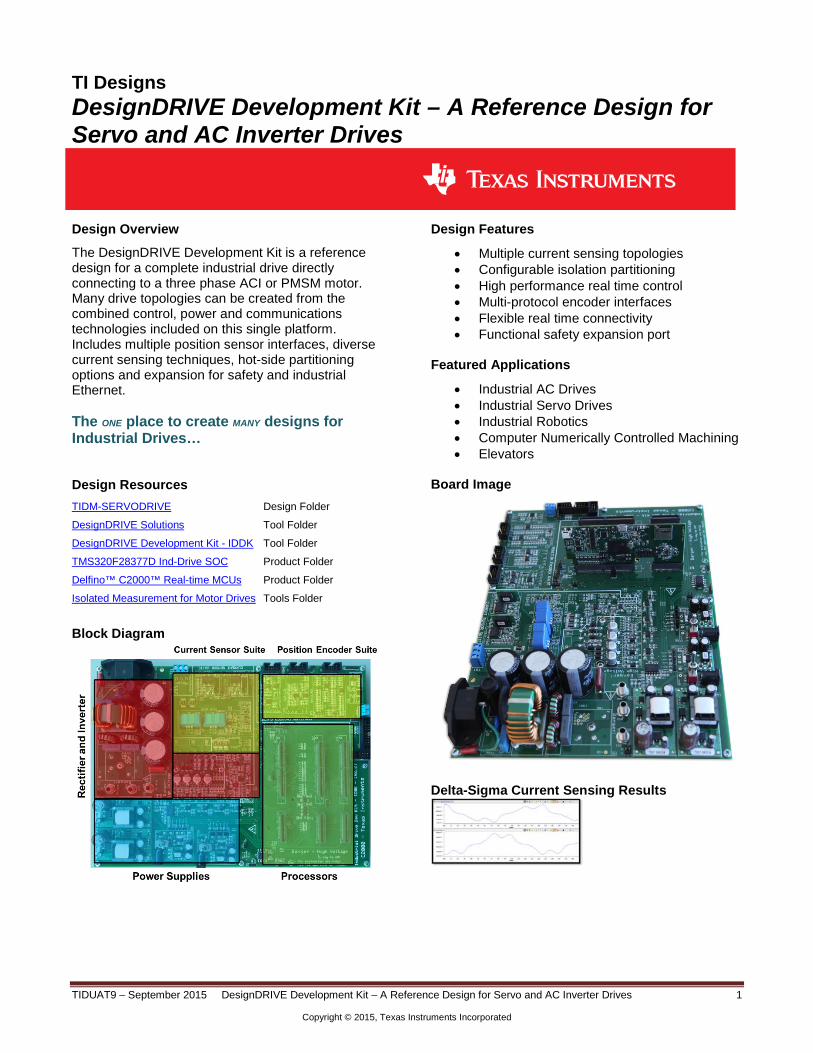
The DesignDRIVE Development Kit is a reference design for a complete industrial drive directly connecting to a three phase ACI or PMSM motor. Many drive topologies can be created from the combined control, power and communications technologies included on this single platform. Includes multiple position sensor interfaces, diverse current sensing techniques, hot-side partitioning options and expansion for safety and industrial Ethernet. The ONE place to create MANY designs for Industrial Drives…
Design Resources TIDM-SERVODRIVE Design Folder
DesignDRIVE Solutions Tool Folder
DesignDRIVE Development Kit - IDDK Tool Folder
TMS320F28377D Ind-Drive SOC Product Folder
Delfino™ C2000™ Real-time MCUs Product Folder
Isolated Measurement for Motor Drives Tools Folder
Block Diagram
Design Features
• Multiple current sensing topologies • Configurable isolation partitioning • High performance real time control • Multi-protocol encoder interfaces • Flexible real time connectivity • Functional safety expansion port
Featured Applications
• Industrial AC Drives • Industrial Servo Drives • Industrial Robotics • Computer Numerically Controlled Machining • Elevators
Board Image
Delta-Sigma Current Sensing Results

www.ti.com
TIDUAT9 – September 2015 - DesignDRIVE Development Kit – A Reference Design for Servo and AC Inverter Drives 2
Copyright © 2015, Texas Instruments Incorporated
1 Key System Specifications
Functional Block Macro Reference Macro Function Power Supplies M2 Isolated DC-DC converter – 400 V to 15 V
M3 DC-Power Supply – Linear Reg 15 V – 5 V to 3.3 V M8 Isolated DC/DC Converter – 400 V to 15 V M9 DC-Power Supply – Linear Reg 15 V – 5 V to 3.3 V
Rectifier and Inverter M1 AC Main Power Entry M4 3-Phase Inverter
Current Sensor Suite M5 Flux Gate – Motor Current Sense Interface M6 Overcurrent Protection M7 Sigma-Delta – Motor Current Sense Interface
Position Encoder Suite M10 QEP Interface M11 Resolver Interface M12 EnDat Encoder Interface
M13 Sin-Cos Encoder Interface Processors Main board All other functions
Figure 1: Hardware Macros in the IDDK and Their Functions
www.ti.com
TIDUAT9 – September 2015 - DesignDRIVE Development Kit – A Reference Design for Servo and AC Inverter Drives 3
Copyright © 2015, Texas Instruments Incorporated
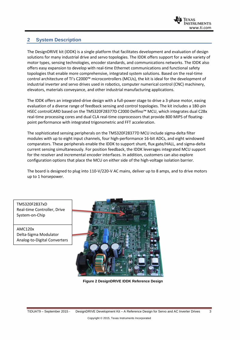
2 System Description The DesignDRIVE kit (IDDK) is a single platform that facilitates development and evaluation of design solutions for many industrial drive and servo topologies. The IDDK offers support for a wide variety of motor types, sensing technologies, encoder standards, and communications networks. The IDDK also offers easy expansion to develop with real-time Ethernet communications and functional safety topologies that enable more comprehensive, integrated system solutions. Based on the real-time control architecture of TI’s C2000™ microcontrollers (MCUs), the kit is ideal for the development of industrial inverter and servo drives used in robotics, computer numerical control (CNC) machinery, elevators, materials conveyance, and other industrial manufacturing applications. The IDDK offers an integrated-drive design with a full-power stage to drive a 3-phase motor, easing evaluation of a diverse range of feedback sensing and control topologies. The kit includes a 180-pin HSEC controlCARD based on the TMS320F28377D C2000 Delfino™ MCU, which integrates dual C28x real-time processing cores and dual CLA real-time coprocessors that provide 800 MIPS of floating-point performance with integrated trigonometric and FFT acceleration. The sophisticated sensing peripherals on the TMS320F28377D MCU include sigma-delta filter modules with up to eight input channels, four high-performance 16-bit ADCs, and eight windowed comparators. These peripherals enable the IDDK to support shunt, flux gate/HALL, and sigma-delta current sensing simultaneously. For position feedback, the IDDK leverages integrated MCU support for the resolver and incremental encoder interfaces. In addition, customers can also explore configuration options that place the MCU on either side of the high-voltage isolation barrier. The board is designed to plug into 110-V/220-V AC mains, deliver up to 8 amps, and to drive motors up to 1 horsepower.
Figure 2 DesignDRIVE IDDK Reference Design
TMS320F2837xD Real-time Controller, Drive System-on-Chip
AMC120x Delta-Sigma Modulator Analog-to-Digital Converters

www.ti.com
TIDUAT9 – September 2015 - DesignDRIVE Development Kit – A Reference Design for Servo and AC Inverter Drives 4
Copyright © 2015, Texas Instruments Incorporated
2.1 TMS320F2837x C2000™ Delfino™ Microcontrollers The 32-bit Delfino™ series of C2000 Real-time Control microcontrollers brings leading floating-point performance and analog integration to real-time control applications. The Delfino series of microcontrollers simplifies development and delivers high performance for demanding real-time applications. The Delfino series features the new dual-core microcontroller running at 200 MHz on each CPU and also has single-core options running up to 300 MHz. With a high-performance core, control-optimized peripherals, integrated analog and scalable development platform, the Delfino series of microcontrollers can reduce system cost, increase system reliability and boost performance for applications such as industrial power electronics, power delivery, renewable energy and smart sensing.
Key Features Key Benefits
• Dual-core C28x at 200 MHz each • Floating Point Unit • Trigonometric math unit (TMU) • Viterbi Complex Unit (VCU) • Two programmable 32-bit floating-point
real-time accelerators (CLAs) on chip • Up to 1 MB of Flash • Dual DMA controllers • High Resolution PWMs (down to 55ps) • Four 16 bit ADCs, 1 MSPS • 32-bit QEP and Capture modules • Programmable PWM Trip
• Leading 32-bit performance for
real-time control applications • Reduced system cost through
integrated high performance analog
• Improved application performance and efficiency
2.2 AMC1204DW – Delta-Sigma Modulators • Galvanically isolated current sensing solution • 16-bit output at 78.1 kSPS • ±10 A at <0.3% (uncalibrated accuracy) • 78dB SNR (min)

www.ti.com
TIDUAT9 – September 2015 - DesignDRIVE Development Kit – A Reference Design for Servo and AC Inverter Drives 5
Copyright © 2015, Texas Instruments Incorporated
3 Block Diagram
Figure 3 A Block Diagram of TIDM-SERVODRIVE, TMDXIDDK377D

www.ti.com
TIDUAT9 – September 2015 - DesignDRIVE Development Kit – A Reference Design for Servo and AC Inverter Drives 6
Copyright © 2015, Texas Instruments Incorporated
4 System Design Theory This design has a low-voltage domain represented by the controller and a high-voltage domain represented by the rectifier and the inverter domain. Please refer to the following documentation for more details:
• DesignDRIVE Development Kit IDDK v2.2 - User’s Guide • DesignDRIVE Development Kit IDDK v2.2 - Hardware Reference Guide
5 Getting Started Hardware As the default configuration, the experiment uses one common HOT GND that connects the control and power circuits. (See entry 4 of Table 3-2, Power Supply Connection Configuration in the DesignDRIVEDevelopment Kit IDDK v2.2 Hardware Reference Guide [SPRUI23].) For setting up the experimental hardware, perform the following steps:
1. Ensure that jumpers [Main]-J6, [Main]-J7, and [Main]-J8 in front of macro M9, are populated. 2. Ensure that resistors [Main] R8 through R13 are populated. 3. Ensure that GND plane resistors R14 and R15 are mounted. (See Figure 3-12,Various GND Planes onthe Bottom Side of Board and Figure 3-13, Default Connection of Various GND Planes of DesignDRIVE Development Kit IDDK v2.2 Hardware Reference Guide [SPRUI23].) 4. Unpack the TMDXCNCD28377D control card. 5. Slide the card into the connector slot of [Main]-H1. (Push down using even pressure on both ends of the card until it cannot slide further. To remove the card, spread open the retaining clips and pull the card out, applying even force at the edges.) 6. Connect a USB cable to connector J1 on the control card. (The control card isolates the JTAG signals between the C2000 device and the computer. LED D2 on the control card should light.) 7. Ensure that toggle switch [M9]-SW1 is in the Int position. 8. Connect an isolated 15-V DC-power supply to [M9]-JP1. 9. Turn on toggle switch [M9]-SW1. ([M9]-LD1 should turn on.
NOTE: More LEDs on the control card light up. These LEDs indicate that the control card is receiving power from the board. Connect the motor to the [Main]-TB1 terminals only after finishing the first incremental build
10. Apply the DC-bus power only when the guide instructs. Two options exist to get DC-bus power:
• To use an external, variable DC-power supply, do the following: (a) Set the power-supply output to zero. (b) Connect [Main]-BS2 and [Main]-BS3 to the + and – terminals of the DC-
power supply, respectively.
• To use AC-Mains power, do the following: (a) Connect [Main]-BS1 to [Main]-BS2 using a banana plug cord. (b) Connect the end of the AC-power cord to [Main]-P1. (c) Set the output of the variac to zero. (d) Connect the variac to the wall supply through an isolator.
(e) Connect the other end fo the AC-power cord to the output of the variac.
www.ti.com
TIDUAT9 – September 2015 - DesignDRIVE Development Kit – A Reference Design for Servo and AC Inverter Drives 7
Copyright © 2015, Texas Instruments Incorporated
6 Getting Started Firmware - Installing Code Composer and controlSUITE 1. If not already installed, install Code Composer v6.x or later from http://www.ti.com/tool/CCSTUDIO 2. Go to http://www.ti.com/controlsuite 3. Run the controlSUITE installer.
NOTE: Allow the installer to download and update any automatically-checked software for C2000. Please see DesignDRIVE Development Kit IDDK v2.2 - User’s Guide for complete instructions for setting up the project.

www.ti.com
TIDUAT9 – September 2015 - DesignDRIVE Development Kit – A Reference Design for Servo and AC Inverter Drives 8
Copyright © 2015, Texas Instruments Incorporated
7 Design Files
7.1 Schematics To download the Schematics for each board, see the design files at http://www.ti.com/tool/TIDM-SERVODRIVE.

www.ti.com
TIDUAT9 – September 2015 - DesignDRIVE Development Kit – A Reference Design for Servo and AC Inverter Drives 9
Copyright © 2015, Texas Instruments Incorporated
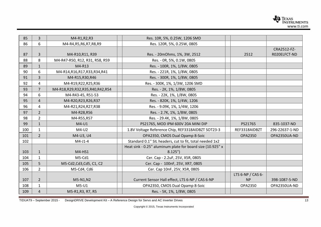
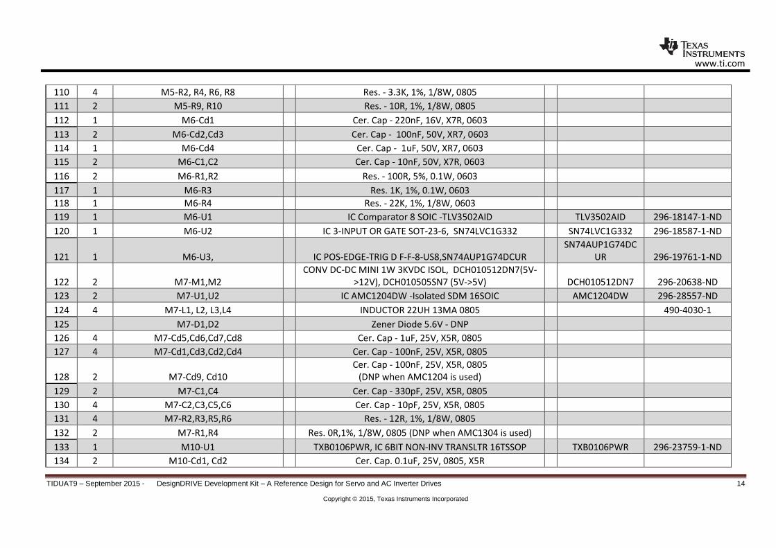
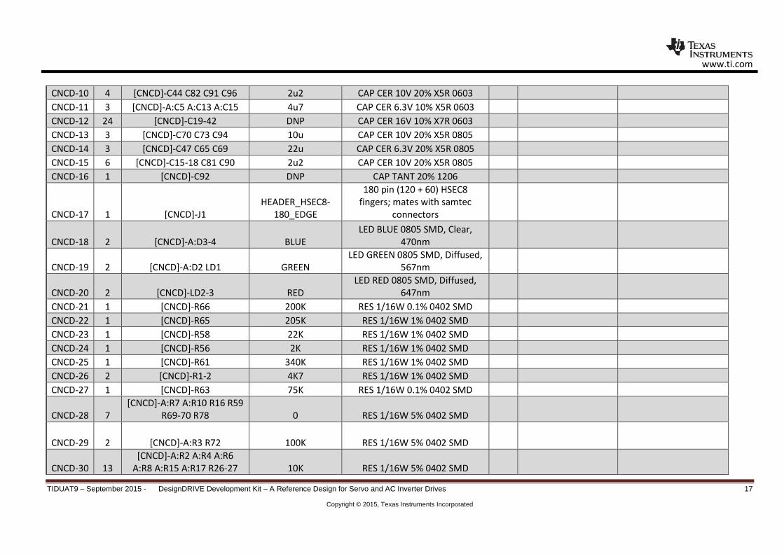
7.2 Bill of Materials To download the Bill of Materials for each board, see the design files at http://www.ti.com/tool/TIDM-SERVODRIVE
Item #
needed per
macro
Reference Part Description and Value Manufacturer Part Number Digikey Part #
1 6 [Main]-U1,U2,U3,U4, U5, U8 Digital Isolator, Quad 4/0, 25Mbps, ISO7220CD ISO7220CD 296-26075-5-ND 2 1 [Main]-U7 Digital Isolator, Quad 4/0, 25Mbps, ISO7221ADR ISO7221ADR 296-21955-2-ND 3 1 [Main]-U6 IC 3-INPUT OR GATE SOT-23-6, SN74LVC1G332 SN74LVC1G332 296-18587-1-ND
4 1 [Main]-U9 ISO1050 - IC TXRX CAN 5V 8SOP ISO1050 296-24818-1-ND 5 1 [Main]-U11 AMC1204DW, SOIC16 - Isolated SDM AMC1204DW 296-28557-ND
6 3 [Main]-C1,C2,C3 Electrolytic Capacitors - Leaded 400V, 220uF 25X30 20% 1189-2025-ND
7 1 [Main]-C5 Metal Poly Cap. 0.22uF, 400V DC, Lead spacing 0.591"
(15.00mm) - EF4224 EF4224-ND
8 19
[Main]-Cd1,Cd2,Cd3,Cd4,Cd5,Cd6,Cd7,Cd8, Cd9,Cd10,Cd11, Cd12, Cd13, Cd15,
Cd16, Cd17, Cd18, Cd20, Cd22, Cer. Cap - 100nF, 25V, XR7, 0805
9 1 [Main]-Cd21 Cer. Cap - 100nF, 25V, XR7, 0805 (DNP when AMC1204 is
used) 10 1 [Main]-Cd14 Cer. Cap - 470nF, 25V, XR7, 0805 11 1 [Main]-Cd19 Cer. Cap - 1uF, 25V, XR7, 0805

www.ti.com
TIDUAT9 – September 2015 - DesignDRIVE Development Kit – A Reference Design for Servo and AC Inverter Drives 10
Copyright © 2015, Texas Instruments Incorporated
12 2 [Main]-C9,C10 Cer. Cap - 10pF, 25V, X5R, 0805 13 2 [Main]-C8 Cer. Cap - 330pF, 25V, X5R, 0805 14 7 [Main]-R1,R2,R3,R4,R5,R6,R7 Res. - 15K, 1%,1/8W, 0805 15 1 [Main]-R57 Res. 10K, 5%, 1/8W, 0805
16 12 [Main]-R24, R31, R32, R33, R35, R38,
R39, R42, R45, R54, R55, R56 Res. -0R ,1/8W, 0805 17 1 [Main]-R53 Res. -0R ,1/8W, 0805 (DNP when AMC1304 is used)
18 19
[Main]-R17, R18, R19, R20, R21, R22, R23, R25, R26, R27, R28, R29, R30,
R34, R36, R40, R41, R43, R44 DNP : Res. -0R ,1/8W, 0805, Determines isolation settings
!! Consult before populating
19 2 [Main]-RS1 , RS2 Res. - 20mOhms, 1%, 3W, 2512 CRA2512-FZ-
R020ELFCT-ND 20 2 [Main]-PR1, PR2 Power Resistor 150K, 1/2W 541-150KVCT-ND
21 8 [Main]-
R8,R9,R10,R11,R12,R13,R14,R15 Res - 0E, 1/4W, 1206 22 2 [Main]-R16, R37 Res. 1K ,1/8W, 0805 23 2 [Main]-R47, R48 Res. 1M ,1/8W, 1206, 1%
24 1 [Main]-R49 Res. 1.5K ,1/8W, 1206, 1% 25 1 [Main]-R50 Res. 1.5K ,1/8W, 0805, 1% 26 2 [Main]-R51, R52 Res. 12R ,1/8W, 0805, 1% 27 1 [Main]-L1 INDUCTOR 22UH 13MA 0805 490-4030-1 28 1 [Main]-LD1 LED, green, 0805 Mfr # PG1112H-TR PG1112H-TR 404-1021-1-ND 29 1 [Main]-P1 CONN AC RECEPT 7MM R/A RND PCB Q218-ND
30
[Main]-J1,J2,J3,J4,J5,J6,J7,J8,H9,J10,J12, J13,
J14, J15, J16, J19, J20, J21 Standard 0.1'' SIL headers, cut to fit, total needed 1x2 31 [Main]-H5, J17, J9, H10, J18 Standard 0.1'' SIL headers, cut to fit, total needed 1x3 32 4 [Main]-H3, H4, H6, H15 8 pos keyed 0.1" vertical header 2x4 70246-0801

www.ti.com
TIDUAT9 – September 2015 - DesignDRIVE Development Kit – A Reference Design for Servo and AC Inverter Drives 11
Copyright © 2015, Texas Instruments Incorporated
33 1 [Main]-H13 20 pos keyed 0.1" vertical header 2x10 70246-2002 34 [Main]-H2 Standard 0.1'' SIL headers, cut to fit, total needed 1x5 35 1 [Main]-TB1 3 input connector for connecting Motor ED1610-ND 36 1 [Main]-H14 Terminals (2 screw) 5.08mm, 7.5mm wide ED1975-ND
37 3 [Main]-H1, H7, H8 180 pin (120 + 60) HSEC8 socket, samtec Mfr # HSEC8-
130-01-L-DV-A & HSEC8-160-01-L-DV-A-BL
HSEC8-130-01-L-DV-A & HSEC8-
160-01-L-DV-A-BL SAM8081-ND &
SAM8084-ND 38 3 [Main]-BS1,BS2,BS3 Banana Connector and Screws 501-1115-ND 39 1 M1-C1 CAP FILM 0.047UF 760VDC RADIAL 495-3972-ND 40 2 M1-C2,C3 CAP FILM 4n7/2KVdc RADIAL 399-5901-nd 41 1 M1-F1 Fuse Holder 486-1160-ND 42 1 M1-Fuse-F1 FUSE 250V IEC SLO 5X20MM 10A F2425-ND 43 1 M1-RT1 CURRENT LIMITR INRSH 10 OHM 15A - SL32 10015 SL32 10015 570-1058-ND 44 1 M1-VAR1 VARISTOR 275V RMS 10MM RADIAL 495-1433-ND 45 1 M1-DB1 RECT BRIDGE 35A 600V - GBPC3506W-G GBPC3506W-G 641-1384-ND 46 1 M1-T1 8121-RC, CHOKE COMM MODE W/HDR 1mH 20A M8916-ND 47 2 M1-L1, L2 INDUCT PWR 7.8UH TH 553-1503-ND 48 1 M2-M2 400V to 15V auxially power supply, PR902 PR902 49 1 M8-M8 400V to 15V auxially power supply, PR902 PR902 50 1 M3-C1 Cer. Cap - 22u, 25V, X5R, 1206 51 1 M3-C2 Cer. Cap - 10u, 25V, X5R, 1206 52 1 M3-C3 Cer. Cap - 4u7, 25V, X5R, 0805 53 1 M3-C4 Cer. Cap - 0.1uf, 25V, X5R, 0805 54 2 M3-C5,C6 Elec. Cap - 330uf/ 63V, Alum, radial P15739CT-ND 55 1 M3-R1 Res. - 330R, 1%, 0.1W, 0805 56 1 M3-R2 Res. - 470R, 5%, 0.1W, 0805 57 1 M3-LD1 LED, green, 0805 404-1021-1-ND 58 1 M3-SW1 Toggle Switch - Miniature, SPDT CKN1002-ND

www.ti.com
TIDUAT9 – September 2015 - DesignDRIVE Development Kit – A Reference Design for Servo and AC Inverter Drives 12
Copyright © 2015, Texas Instruments Incorporated
59 1 M3-M1 Power Module - PTH08080 PTH08080 296-20432-ND 60 1 M3-U1 LDO - 3.3V - TPS79533 296-13810-1-ND 61 1 M3-JP1 Power jack 2.1 x 5.5 mm CP-002AH-ND 62 1 M9-C1 Cer. Cap - 22u, 25V, X5R, 1206 63 1 M9-C2 Cer. Cap - 10u, 25V, X5R, 1206 64 1 M9-C3 Cer. Cap - 4u7, 25V, X5R, 0805 65 1 M9-C4 Cer. Cap - 0.1uf, 25V, X5R, 0805 66 2 M9-C5,C6 Elec. Cap - 330uf, 63V, Alum, radial P15739CT-ND 67 1 M9-R1 Res. - 330R, 1%, 0.1W, 0805 68 1 M9-R2 Res. - 470R, 5%, 0.1W, 0805 69 1 M9-LD1 LED, green, 0805 404-1021-1-ND 70 1 M9-SW1 Toggle Switch - Miniature, SPDT CKN1002-ND 71 1 M9-M1 Power Module - PTH08080 PTH08080 296-20432-ND 72 1 M9-U1 LDO - 3.3V - TPS79533 TPS79533 296-13810-1-ND 73 1 M9-JP1 Power jack 2.1 x 5.5 mm CP-002AH-ND 74 4 M4-C1,C2,C3,Cd5 Elec. Cap - 100uF, 50V, 20%, SMD 565-2133-1-ND 75 8 M4-C4,C5,C6, Cd1,Cd2,Cd3,Cd4,Cd7 Cer. Cap - 2.2uF, 25V, X5R, 0805 76 1 M4-Cd10 Cer. Cap - 2.2uF, 25V, X5R, 1206 77 6 M4-C7,C8,C9,C10,C11,C12 Cer. Cap - 220p, 50V, X7R, 0805 78 1 M4-C13 Cer. Cap - 22nF, 25V, X5R, 0805 79 M4-C15, C16, C17,C18 DNP 80 4 M4-C21-24 Cer. Cap - 47nF, 50V, 5%, 0805 81 4 M4-Cd6,Cd8,Cd9,Cd12 Cer. Cap - 100nF, 50V, XR7, 0805 82 1 M4-Cd11 Cer. Cap - 4.7uF, 25V, X7R, 0805 83 3 M4-D1,D2,D3 US1J-13-F, Diode Ultra Fast SW 600V 1A US1J-13-F US1J-FDICT-ND 84 3 M4-D4,D5,D6 SMAZ16-TP, Diode Zener 1W 16V SMA SMAZ16-TP SMAZ16-FDICT-ND
www.ti.com
TIDUAT9 – September 2015 - DesignDRIVE Development Kit – A Reference Design for Servo and AC Inverter Drives 13
Copyright © 2015, Texas Instruments Incorporated
85 3 M4-R1,R2,R3 Res. 10R, 5%, 0.25W, 1206 SMD 86 6 M4-R4,R5,R6,R7,R8,R9 Res. 120R, 5%, 0.25W, 0805
87 3 M4-R10,R11, R39 Res. - 20mOhms, 1%, 3W, 2512 2512 CRA2512-FZ-
R020ELFCT-ND 88 8 M4-R47-R50, R12, R31, R58, R59 Res. - 0R, 5%, 0.1W, 0805 89 1 M4-R13 Res. - 100R, 1%, 1/8W, 0805 90 6 M4-R14,R16,R17,R33,R34,R41 Res. - 221R, 1%, 1/8W, 0805 91 3 M4-R15,R30,R46 Res. - 300R, 1%, 1/8W, 0805 92 4 M4-R19,R22,R25,R36 Res. - 300K, 1%, 1/3W, 1206 SMD 93 7 M4-R18,R29,R32,R35,R40,R42,R54 Res. - 2K, 1%, 1/8W, 0805 94 6 M4-R43-45, R51-53 Res. - 22K, 1%, 1/8W, 0805 95 4 M4-R20,R23,R26,R37 Res. - 820K, 1%, 1/4W, 1206 96 4 M4-R21,R24,R27,R38 Res. - 9.09K, 1%, 1/4W, 1206 97 2 M4-R28,R56 Res. - 2.7K, 1%, 1/8W, 0805 98 2 M4-R55,R57 Res. - 29.4K, 1%, 1/8W, 0805 99 1 M4-U1 PS21765, MOD IPM 600V 20A MINI DIP PS21765 835-1037-ND
100 1 M4-U2 1.8V Voltage Reference Chip, REF3318AIDBZT SOT23-3 REF3318AIDBZT 296-22637-1-ND 101 2 M4-U3, U4 OPA2350, CMOS Dual Opamp 8-Soic OPA2350 OPA2350UA-ND 102 M4-J1-4 Standard 0.1'' SIL headers, cut to fit, total needed 1x2
103 1 M4-HS1 Heat sink - 0.25" aluminum plate for board size (10.925" x
8.125") 104 1 M5-Cd1 Cer. Cap - 2.2uF, 25V, X5R, 0805 105 5 M5-Cd2,Cd3,Cd5, C1, C2 Cer. Cap - 100nF, 25V, XR7, 0805 106 2 M5-Cd4, Cd6 Cer. Cap 10nF, 25V, X5R, 0805
107 2 M5-N1,N2 Current Sensor Hall effect, LTS 6-NP / CAS 6-NP LTS 6-NP / CAS 6-
NP 398-1087-5-ND 108 1 M5-U1 OPA2350, CMOS Dual Opamp 8-Soic OPA2350 OPA2350UA-ND 109 4 M5-R1,R3, R7, R5 Res. - 5K, 1%, 1/8W, 0805
www.ti.com
TIDUAT9 – September 2015 - DesignDRIVE Development Kit – A Reference Design for Servo and AC Inverter Drives 14
Copyright © 2015, Texas Instruments Incorporated
110 4 M5-R2, R4, R6, R8 Res. - 3.3K, 1%, 1/8W, 0805 111 2 M5-R9, R10 Res. - 10R, 1%, 1/8W, 0805 112 1 M6-Cd1 Cer. Cap - 220nF, 16V, X7R, 0603 113 2 M6-Cd2,Cd3 Cer. Cap - 100nF, 50V, XR7, 0603 114 1 M6-Cd4 Cer. Cap - 1uF, 50V, XR7, 0603 115 2 M6-C1,C2 Cer. Cap - 10nF, 50V, X7R, 0603 116 2 M6-R1,R2 Res. - 100R, 5%, 0.1W, 0603 117 1 M6-R3 Res. 1K, 1%, 0.1W, 0603 118 1 M6-R4 Res. - 22K, 1%, 1/8W, 0603 119 1 M6-U1 IC Comparator 8 SOIC -TLV3502AID TLV3502AID 296-18147-1-ND 120 1 M6-U2 IC 3-INPUT OR GATE SOT-23-6, SN74LVC1G332 SN74LVC1G332 296-18587-1-ND
121 1 M6-U3, IC POS-EDGE-TRIG D F-F-8-US8,SN74AUP1G74DCUR SN74AUP1G74DC
UR 296-19761-1-ND
122 2 M7-M1,M2 CONV DC-DC MINI 1W 3KVDC ISOL, DCH010512DN7(5V-
>12V), DCH010505SN7 (5V->5V) DCH010512DN7 296-20638-ND 123 2 M7-U1,U2 IC AMC1204DW -Isolated SDM 16SOIC AMC1204DW 296-28557-ND 124 4 M7-L1, L2, L3,L4 INDUCTOR 22UH 13MA 0805 490-4030-1 125 M7-D1,D2 Zener Diode 5.6V - DNP 126 4 M7-Cd5,Cd6,Cd7,Cd8 Cer. Cap - 1uF, 25V, X5R, 0805 127 4 M7-Cd1,Cd3,Cd2,Cd4 Cer. Cap - 100nF, 25V, X5R, 0805
128 2 M7-Cd9, Cd10 Cer. Cap - 100nF, 25V, X5R, 0805
(DNP when AMC1204 is used) 129 2 M7-C1,C4 Cer. Cap - 330pF, 25V, X5R, 0805 130 4 M7-C2,C3,C5,C6 Cer. Cap - 10pF, 25V, X5R, 0805 131 4 M7-R2,R3,R5,R6 Res. - 12R, 1%, 1/8W, 0805 132 2 M7-R1,R4 Res. 0R,1%, 1/8W, 0805 (DNP when AMC1304 is used) 133 1 M10-U1 TXB0106PWR, IC 6BIT NON-INV TRANSLTR 16TSSOP TXB0106PWR 296-23759-1-ND 134 2 M10-Cd1, Cd2 Cer. Cap. 0.1uF, 25V, 0805, X5R

www.ti.com
TIDUAT9 – September 2015 - DesignDRIVE Development Kit – A Reference Design for Servo and AC Inverter Drives 15
Copyright © 2015, Texas Instruments Incorporated
135 3 M10-C1, C2, C3 Cer. Cap. 10nF, 25V, 0805, X5R 136 3 M10-R1, R2, R3 Res. 47K, 5%, 1/8W, 0805 137 1 M11-C1 Cer. Cap - 1u, 25V, X5R, 0805 138 1 M11-C2 Cer. Cap - 47n, 25V, X7R, 0805 139 1 M11-C3 Cer. Cap - 1n2, 25V, X7R, 0805 140 1 M11-C4 Cer. Cap - 4n7, 25V, X7R, 0805 141 2 M11-C5,C6 Cer. Cap - 220p, 25V, X7R, 0805 142 4 M11-C7,C8,C13,C18 Cer. Cap - 1n, 25V, X7R, 0805 143 2 M11-C9,C14 Cer. Cap - 47p, 25V, X7R, 0805 144 4 M11-C10,C11,C15,C16 Cer. Cap - 330p, 25V, X7R, 0805 145 7 M11-C12,C17,C19,Cd1,Cd3,Cd4,Cd6 Cer. Cap - 100n, 25V, X7R, 0805 146 2 M11-Cd2,Cd5 Cer. Cap - 2u2, 25V, X5R, 0805 147 2 M11-L1,L3 Inductor Bead, 60Ohm, 0805 148 1 M11-L2 Res. - 0R0, 0805 149 2 M11-R1,R24 Res. - 47R, 1%, 0.1W, 0805 150 2 M11-R2,R3 Res. - 3K3, 1%, 0.1W, 0805 151 2 M11-R4,R9 Res. - 68K, 1%, 0.1W, 0805 152 2 M11-R5,R7 Res. - 5K1, 1%, 0.1W, 0805 153 8 M11-R6,R8,R13,R14,R19,R20,R22,R23 Res. - 10K, 1%, 0.1W, 0805 154 2 M11-R10,R16 Res. - 47K, 1%, 0.1W, 0805 155 4 M11-R11,R12,R17,R18 Res. - 11K, 1%, 0.1W, 0805 156 2 M11-R15,R21 Res. - 2K, 1%, 0.1W, 0805 157 1 M11-U1 IC OPAMP GP R-R 18MHZ LN OPA2209 8SOIC OPA2209 296-27783-1-ND 158 1 M11-U2 IC OPAMP GP R-R 5.1MHZ TLV2772 8SOIC TLV2772 296-10677-1-ND 159 1 M11-U3 TLV2771 in SOT23-5 footprint TLV2771 296-1347-1-ND 160 4 M12-Cd1-Cd4 Cer. Cap - 100nF , 25V, 0805 161 5 M12-C1-C5 Cer. Cap - 330pF, 25V, X5R, 0805

www.ti.com
TIDUAT9 – September 2015 - DesignDRIVE Development Kit – A Reference Design for Servo and AC Inverter Drives 16
Copyright © 2015, Texas Instruments Incorporated
162 3 M12-R1,R2,R3 Res. - 10R, 5%, 0.1W, 0805 163 1 M12-R4 Res. - 120R, 1%, 0.1W, 0805 164 1 M12-R5 Res. - 47K, 5%, 0.1W, 0805 165 2 M12-R6,R7 Res. - 150K, 5%, 0.1W, 0805 166 1 M12-U1 Voltage Translator, 4 channel, TXB0104 - TSSOP-14 TXB0104 296-21929-1-ND 167 2 M12-U2,U3 Transceiver, RS485 Half Duplex, SOIC-8 SN65HVD3088ED 296-17172-5-ND 168 1 M12-U4 High Side Switch, TPS27082L - SOT-23-6 TPS27082L 296-35595-1-ND 169 3 M13-C1-C3 Cer. Cap - 10pF, 25V, NPO, 0805 170 3 M13-Cd1-Cd3 Cer. Cap - 100nF , 25V, 0805 171 8 M13-R1-R4,R9,R10,R16,R17 Res. - 20K, 1%, 0.1W, 0805 172 6 M13-R5-R8,R11,R12 Res. - 10K, 1%, 0.1W, 0805 173 3 M13-R13-R15 Res. - 120R, 1%, 0.1W, 0805 174 2 M13-U1,U2 OpAmp OPA2350, SOIC-8 OPA2350 OPA2350UA-ND
CNCD-0
Item # QTY Reference Value Part Description and Value Mfg Manufacturer
Part Number Digikey Part #
CNCD-01 69
[CNCD]-A:C1 A:C6-12 A:C14 A:C16-17 A:C20-30 C1-3 C7 C10-14 C43 C45 C48-64 C66 C75-80 C83-89 C95 C97-100 100n CAP CER 16V 10% X7R 0402
CNCD-02 1 [CNCD]-A:C4 10n CAP CER 16V 10% X7R 0402 CNCD-03 2 [CNCD]-C4-5 1n CAP CER 16V 10% X7R 0402 CNCD-04 1 [CNCD]-C46 470n CAP CER 6.3V 10% X5R 0402 CNCD-05 2 [CNCD]-C6 C67 DNP CAP CER 16V 10% X7R 0402 CNCD-06 2 [CNCD]-C8-9 15p CAP CER 50V NP0 0402 CNCD-07 2 [CNCD]-A:C18-19 27p CAP CER 50V NP0 0402 CNCD-08 1 [CNCD]-C68 33p CAP CER 50V NP0 0402 CNCD-09 4 [CNCD]-A:C2 C71-72 C74 10u CAP CER 6.3V 20% X5R 0603
www.ti.com
TIDUAT9 – September 2015 - DesignDRIVE Development Kit – A Reference Design for Servo and AC Inverter Drives 17
Copyright © 2015, Texas Instruments Incorporated
CNCD-10 4 [CNCD]-C44 C82 C91 C96 2u2 CAP CER 10V 20% X5R 0603 CNCD-11 3 [CNCD]-A:C5 A:C13 A:C15 4u7 CAP CER 6.3V 10% X5R 0603 CNCD-12 24 [CNCD]-C19-42 DNP CAP CER 16V 10% X7R 0603 CNCD-13 3 [CNCD]-C70 C73 C94 10u CAP CER 10V 20% X5R 0805 CNCD-14 3 [CNCD]-C47 C65 C69 22u CAP CER 6.3V 20% X5R 0805 CNCD-15 6 [CNCD]-C15-18 C81 C90 2u2 CAP CER 10V 20% X5R 0805 CNCD-16 1 [CNCD]-C92 DNP CAP TANT 20% 1206
CNCD-17 1 [CNCD]-J1 HEADER_HSEC8-
180_EDGE
180 pin (120 + 60) HSEC8 fingers; mates with samtec
connectors
CNCD-18 2 [CNCD]-A:D3-4 BLUE LED BLUE 0805 SMD, Clear,
470nm
CNCD-19 2 [CNCD]-A:D2 LD1 GREEN LED GREEN 0805 SMD, Diffused,
567nm
CNCD-20 2 [CNCD]-LD2-3 RED LED RED 0805 SMD, Diffused,
647nm CNCD-21 1 [CNCD]-R66 200K RES 1/16W 0.1% 0402 SMD CNCD-22 1 [CNCD]-R65 205K RES 1/16W 1% 0402 SMD CNCD-23 1 [CNCD]-R58 22K RES 1/16W 1% 0402 SMD CNCD-24 1 [CNCD]-R56 2K RES 1/16W 1% 0402 SMD CNCD-25 1 [CNCD]-R61 340K RES 1/16W 1% 0402 SMD CNCD-26 2 [CNCD]-R1-2 4K7 RES 1/16W 1% 0402 SMD CNCD-27 1 [CNCD]-R63 75K RES 1/16W 0.1% 0402 SMD
CNCD-28 7 [CNCD]-A:R7 A:R10 R16 R59
R69-70 R78 0 RES 1/16W 5% 0402 SMD
CNCD-29 2 [CNCD]-A:R3 R72 100K RES 1/16W 5% 0402 SMD
CNCD-30 13 [CNCD]-A:R2 A:R4 A:R6
A:R8 A:R15 A:R17 R26-27 10K RES 1/16W 5% 0402 SMD

www.ti.com
TIDUAT9 – September 2015 - DesignDRIVE Development Kit – A Reference Design for Servo and AC Inverter Drives 18
Copyright © 2015, Texas Instruments Incorporated
R29 R62 R71 R73-74
CNCD-31 4 [CNCD]-A:R5 A:R9 A:R11-12 1K RES 1/16W 5% 0402 SMD CNCD-32 4 [CNCD]-A:R16 R11 R24-25 2K2 RES 1/16W 5% 0402 SMD CNCD-33 7 [CNCD]-R5-10 R14 39 RES 1/16W 5% 0402 SMD CNCD-34 1 [CNCD]-R22 510K RES 1/16W 5% 0402 SMD CNCD-35 2 [CNCD]-R18-19 56K RES 1/16W 5% 0402 SMD CNCD-36 4 [CNCD]-A:R1 R12-13 R60 680 RES 1/16W 5% 0402 SMD CNCD-37 4 [CNCD]-A:R13-14 R15 R28 DNP RES 1/16W 5% 0402 SMD CNCD-38 1 [CNCD]-R21 120K RES 1/10W 1% 0603 SMD CNCD-39 1 [CNCD]-R23 560K RES 1/10W 1% 0603 SMD CNCD-40 1 [CNCD]-R17 649K RES 1/10W 1% 0603 SMD CNCD-41 1 [CNCD]-R20 750K RES 1/10W 1% 0603 SMD
CNCD-42 27 [CNCD]-R30-42 R44-55 R67-
68 0 RES 1/10W 5% 0603 SMD CNCD-43 3 [CNCD]-R75-77 100K RES 1/10W 5% 0603 SMD CNCD-44 4 [CNCD]-R3-4 R43 R64 DNP RES 1/10W 5% 0603 SMD CNCD-45 1 [CNCD]-R57 0 RES 1/8W 5% 0805 SMD CNCD-46 9 [CNCD]-A:TP1-2 TP1-7 Via, 20 ID, 40 OD (mil)
CNCD-47 1 [CNCD]-U5 micro-SD micro SD Connector+Ejector, 10
(8+2) positions, SMT-top 101-00581-59 101-00581-59-1-ND CNCD-48 1 [CNCD]-A:C31 10n CAP CER 1.5KV 10% X7R 1812 1812SC103KAT1A 478-4735-1-ND CNCD-49 1 [CNCD]-J8 USB micro AB Female USB2.0 1981584-1 A97799CT-ND
CNCD-50 2 [CNCD]-A:SW1 SW1 218-2LPST 2xSPST DIP switch SMT, half-
pitch 218-2LPST CT2182LPST-ND CNCD-51 1 [CNCD]-SW2 4xSPST 4xSPST DIP Switch 281-4LPST CT2184LPST-ND CNCD-52 1 [CNCD]-X1 20MHz, 20ppm 20MHz Crystal, 20ppm 7B-20.000MEEQ-T 887-1303-1-ND CNCD-53 1 [CNCD]-A:U5 IC EEPROM 2KBIT 3MHZ 8SOIC 93LC56C-I/SN 93LC56C-I/SN-ND

www.ti.com
TIDUAT9 – September 2015 - DesignDRIVE Development Kit – A Reference Design for Servo and AC Inverter Drives 19
Copyright © 2015, Texas Instruments Incorporated
CNCD-54 2 [CNCD]-L5-6 60Ohm FERRITE 3A 60OHM@100MHz
0805 SMD BKP2125HS600-T 587-1932-1-ND
CNCD-55 2 [CNCD]-L3-4 220Ohm FERRITE 2A 220OHM@100MHz
0805 SMD BLM21PG221SN1D 490-1054-1-ND CNCD-56 2 [CNCD]-SW3-4 CAS-D20TA Switch SPDT, 2 position CAS-D20TA CASD20JCT-ND CNCD-57 1 [CNCD]-A:X1 12 MHz CRYSTAL 12.000 MHZ 20PF SMD ECS-120-20-30B-TR XC1118CT-ND
CNCD-58 1 [CNCD]-A:U4 IC USB HS DUAL UART/FIFO 64-
QFN FT2232HL 768-1024-1-ND
CNCD-59 2 [CNCD]-A:L1-2 FERRITE 500MA 600 OHM 0805
SMD HZ0805E601R-10 240-2399-1-ND
CNCD-60 5 [CNCD]-A:U6-8 A:U10-11 IC DGTL ISOLATOR 25MBPS 2CH
8SOIC TI ISO7220CD 296-21953-1-ND
CNCD-61 1 [CNCD]-U12 IC OPAMP GP R-R 15MHZ QUAD
14TSSOP TI LMP7709MT/NOPB LMP7709MT/NOPB-ND CNCD-62 6 [CNCD]-J2-7 1x3 HDR Header Male; 1x3, 2mm pitch M22-2510305 952-1312-ND
CNCD-63 3 [CNCD]-A:D1 D1-2 DIODE SCHOTTKY 10V 1A
POWERMITE MBRM110ET1G MBRM110ET1GOSCT-
ND CNCD-64 1 [CNCD]-U16 NTA7002NT1G N-channel MOSFET 30V 0.154A NTA7002NT1G NTA7002NT1GOSCT-ND
CNCD-65 6 [CNCD]-U6-11 NUP4201MR6T1G TVS 4-ch Diode Array, 5V
breakdown NUP4201MR6T1G NUP4201MR6T1GOSCT-
ND
CNCD-66 1 [CNCD]-U13 IC, Voltage Reference, 3.0V,
0.2%, 14uVpp noise TI REF3030AIDBZR 296-26323-1-ND
CNCD-67 1 [CNCD]-U17 IC, Voltage Reference, 3.3V,
0.2%, 14uVpp noise TI REF3033AIDBZR 296-26324-1-ND
CNCD-68 1 [CNCD]-A:U9 3-State Buffer 3-State Buffer, 2 elements x 4
bits TI SN74ALVC244PWR 296-5136-1-ND
CNCD-69 1 [CNCD]-A:U3 IC GATE NAND QUAD 2INP
14TSSOP TI SN74HC03PW 296-29731-1-ND
CNCD-70 1 [CNCD]-U2 SN74LVC2G07DBVR Buffer Line Driver, non-inverting,
32mA TI SN74LVC2G07DBVR 296-13494-1-ND

www.ti.com
TIDUAT9 – September 2015 - DesignDRIVE Development Kit – A Reference Design for Servo and AC Inverter Drives 20
Copyright © 2015, Texas Instruments Incorporated
CNCD-71 1 [CNCD]-A:C3 47u CAP TANT 20% 0805 6.3V TCTP0J476M8R 511-1682-1-ND CNCD-72 1 [CNCD]-C93 68u CAP TANT 10V 20% 1206 TLJA686M010R1500 478-4925-1-ND CNCD-73 1 [CNCD]-U1 MCU F2837x 337pin ZWT BGA TI TMS320F28377DZWT CNCD-74 1 [CNCD]-A:U2 IC ESD-PROT ARRAY 2CH SOT-5 TI TPD2E001DRLR 296-21883-1-ND
CNCD-75 1 [CNCD]-U15 TPS2051BDBVR High-Side Power Distribution
Switch TI TPS2051BDBVR 296-21265-1-ND
CNCD-76 1 [CNCD]-U3 IC SVS Adjustable SON-6/DRY;
PushPull; ActiveLow TI TPS3895ADRY 296-29806-1-ND
CNCD-77 1 [CNCD]-U4 IC SVS Adjustable SON-6/DRY;
OpenCollector TI TPS3897ADRY 296-29810-1-ND
CNCD-78 1 [CNCD]-U14 IC Dual Step Down Converter,
2.25MHz, 600mA/1A TI TPS62420DRC 296-25650-1-ND
CNCD-79 1 [CNCD]-A:U1 IC LDO REG HI-PSRR 3.3V SOT23-
5 TI TPS73033DBV 296-17580-1-ND
CNCD-80 1 [CNCD]-A:J1 CONN RECEPT MINI USB2.0
5POS UX60-MB-5ST H2959CT-ND
CNCD-81 1 [CNCD]-L1 2u2 Inductor Power 2.2uH 1.0A SMD
20% VLF3010AT-2R2M1R0 445-3215-1-ND
CNCD-82 1 [CNCD]-L2 3u3 Inductor Power 3.3uH 0.87A
SMD 20% VLF3010AT-3R3MR87 445-3216-1-ND

www.ti.com
TIDUAT9 – September 2015 - DesignDRIVE Development Kit – A Reference Design for Servo and AC Inverter Drives 21
Copyright © 2015, Texas Instruments Incorporated
7.3 PCB Layout Recommendations Please refer to the DesignDRIVE Development Kit - IDDK v2.2 Hardware Reference Guide for more information on layout and use considerations.
7.3.1 Layout Prints To download the Layout Prints for each board, see the design files at http://www.ti.com/tool/DESIGNNUMBER
TOP SILKSCREEN TOP SOLDER MASK TOP LAYER BOTTOM LAYER BOTTOM SOLDER MASK
7.4 Gerber files To download the Gerber files for each board, see the design files at http://www.ti.com/tool/TIDM-SERVODRIVE

www.ti.com
TIDUAT9 – September 2015 - DesignDRIVE Development Kit – A Reference Design for Servo and AC Inverter Drives 22
Copyright © 2015, Texas Instruments Incorporated
8 Software Files To download the software files for this reference design, please see the link at http://www.ti.com/tool/TIDM-SERVODRIVE and www.ti.com/tool/DesignDRIVE
9 References
1. Texas Instruments Application Report, Noise Analysis in Operational Amplifier Circuits, SLVA043A, 1999 2. Texas Instruments WEBENCH® Design Center, http://www.ti.com/webench 3. Texas Instruments E2E Community, http://e2e.ti.com/
10 About the Author Ramesh Ramamoorthy is a Systems Solutions Engineer at Texas Instruments, where he is responsible for developing reference design solutions for motor drive end equipment. Ramesh has been a motor drives and power electronics engineer and has extensive experience designing and developing analog / digital controllers for a variety of motor drive applications. He has also developed a few reference designs in HVAC and home appliance industry. He earned his Master of Technology in Electrical Engineering from the Indian Institute of Technology, Madras, India. Brian Fortman is responsible for the Industrial Drives and Automation market for C2000™ real-time microcontrollers. Brian has 20+ years of experience in marketing, sales and applications and holds a BSEE from the University of Missouri – Rolla.

IMPORTANT NOTICE FOR TI REFERENCE DESIGNS
Texas Instruments Incorporated ("TI") reference designs are solely intended to assist designers (“Buyers”) who are developing systems thatincorporate TI semiconductor products (also referred to herein as “components”). Buyer understands and agrees that Buyer remainsresponsible for using its independent analysis, evaluation and judgment in designing Buyer’s systems and products.TI reference designs have been created using standard laboratory conditions and engineering practices. TI has not conducted anytesting other than that specifically described in the published documentation for a particular reference design. TI may makecorrections, enhancements, improvements and other changes to its reference designs.Buyers are authorized to use TI reference designs with the TI component(s) identified in each particular reference design and to modify thereference design in the development of their end products. HOWEVER, NO OTHER LICENSE, EXPRESS OR IMPLIED, BY ESTOPPELOR OTHERWISE TO ANY OTHER TI INTELLECTUAL PROPERTY RIGHT, AND NO LICENSE TO ANY THIRD PARTY TECHNOLOGYOR INTELLECTUAL PROPERTY RIGHT, IS GRANTED HEREIN, including but not limited to any patent right, copyright, mask work right,or other intellectual property right relating to any combination, machine, or process in which TI components or services are used.Information published by TI regarding third-party products or services does not constitute a license to use such products or services, or awarranty or endorsement thereof. Use of such information may require a license from a third party under the patents or other intellectualproperty of the third party, or a license from TI under the patents or other intellectual property of TI.TI REFERENCE DESIGNS ARE PROVIDED "AS IS". TI MAKES NO WARRANTIES OR REPRESENTATIONS WITH REGARD TO THEREFERENCE DESIGNS OR USE OF THE REFERENCE DESIGNS, EXPRESS, IMPLIED OR STATUTORY, INCLUDING ACCURACY ORCOMPLETENESS. TI DISCLAIMS ANY WARRANTY OF TITLE AND ANY IMPLIED WARRANTIES OF MERCHANTABILITY, FITNESSFOR A PARTICULAR PURPOSE, QUIET ENJOYMENT, QUIET POSSESSION, AND NON-INFRINGEMENT OF ANY THIRD PARTYINTELLECTUAL PROPERTY RIGHTS WITH REGARD TO TI REFERENCE DESIGNS OR USE THEREOF. TI SHALL NOT BE LIABLEFOR AND SHALL NOT DEFEND OR INDEMNIFY BUYERS AGAINST ANY THIRD PARTY INFRINGEMENT CLAIM THAT RELATES TOOR IS BASED ON A COMBINATION OF COMPONENTS PROVIDED IN A TI REFERENCE DESIGN. IN NO EVENT SHALL TI BELIABLE FOR ANY ACTUAL, SPECIAL, INCIDENTAL, CONSEQUENTIAL OR INDIRECT DAMAGES, HOWEVER CAUSED, ON ANYTHEORY OF LIABILITY AND WHETHER OR NOT TI HAS BEEN ADVISED OF THE POSSIBILITY OF SUCH DAMAGES, ARISING INANY WAY OUT OF TI REFERENCE DESIGNS OR BUYER’S USE OF TI REFERENCE DESIGNS.TI reserves the right to make corrections, enhancements, improvements and other changes to its semiconductor products and services perJESD46, latest issue, and to discontinue any product or service per JESD48, latest issue. Buyers should obtain the latest relevantinformation before placing orders and should verify that such information is current and complete. All semiconductor products are soldsubject to TI’s terms and conditions of sale supplied at the time of order acknowledgment.TI warrants performance of its components to the specifications applicable at the time of sale, in accordance with the warranty in TI’s termsand conditions of sale of semiconductor products. Testing and other quality control techniques for TI components are used to the extent TIdeems necessary to support this warranty. Except where mandated by applicable law, testing of all parameters of each component is notnecessarily performed.TI assumes no liability for applications assistance or the design of Buyers’ products. Buyers are responsible for their products andapplications using TI components. To minimize the risks associated with Buyers’ products and applications, Buyers should provideadequate design and operating safeguards.Reproduction of significant portions of TI information in TI data books, data sheets or reference designs is permissible only if reproduction iswithout alteration and is accompanied by all associated warranties, conditions, limitations, and notices. TI is not responsible or liable forsuch altered documentation. Information of third parties may be subject to additional restrictions.Buyer acknowledges and agrees that it is solely responsible for compliance with all legal, regulatory and safety-related requirementsconcerning its products, and any use of TI components in its applications, notwithstanding any applications-related information or supportthat may be provided by TI. Buyer represents and agrees that it has all the necessary expertise to create and implement safeguards thatanticipate dangerous failures, monitor failures and their consequences, lessen the likelihood of dangerous failures and take appropriateremedial actions. Buyer will fully indemnify TI and its representatives against any damages arising out of the use of any TI components inBuyer’s safety-critical applications.In some cases, TI components may be promoted specifically to facilitate safety-related applications. With such components, TI’s goal is tohelp enable customers to design and create their own end-product solutions that meet applicable functional safety standards andrequirements. Nonetheless, such components are subject to these terms.No TI components are authorized for use in FDA Class III (or similar life-critical medical equipment) unless authorized officers of the partieshave executed an agreement specifically governing such use.Only those TI components that TI has specifically designated as military grade or “enhanced plastic” are designed and intended for use inmilitary/aerospace applications or environments. Buyer acknowledges and agrees that any military or aerospace use of TI components thathave not been so designated is solely at Buyer's risk, and Buyer is solely responsible for compliance with all legal and regulatoryrequirements in connection with such use.TI has specifically designated certain components as meeting ISO/TS16949 requirements, mainly for automotive use. In any case of use ofnon-designated products, TI will not be responsible for any failure to meet ISO/TS16949.IMPORTANT NOTICE
Mailing Address: Texas Instruments, Post Office Box 655303, Dallas, Texas 75265Copyright © 2015, Texas Instruments Incorporated