designing with composites
TRANSCRIPT
Designing With Composites:Engineering FundamentalsA Norplex-Micarta White Paper
Executive Summary
Composites have the unique ability to be customized to the requirements of myriad
applications, driving use well beyond the aerospace and transportation sectors. Because
composites are both heterogeneous and anisotropic, composite design and analysis rely
upon a framework that expands on the traditional mechanics of materials approaches.
This paper will present an overview of these approaches and apply that understanding to a
structured development process which is unique to the design of composite materials.

2 Designing with Composites: Engineering Fundamentals
I. An Introduction to Composites
Designing a composite part is in some ways a designer’s dream, with nearly infinite
combinations of materials that can be utilized to achieve specific design goals. This
flexibility also presents a challenge—specifically, how to choose the inputs and build
the composite most suitable for an application. Even if a designer begins with a set of
assumptions such as material properties desired for a part or a fixed geometry, the sheer
number of options requires a reliable framework for design decisions.
Composites have recently gained much attention due to their weight-adjusted (or specific)
stiffness and strength, which allow for lightweighting in fly- or drive-away applications.
Thus, aerospace, and now, automotive companies are increasing the composite content
in their products. Demand is increasing in other industries based on additional material
properties available in composites.
What accounts for these materials to be sought for specific applications? First, designers
have unprecedented access to empirical data at the coupon level. Secondly, improved (and
lower-cost) analytical software tools have made complex analysis significantly faster and
more cost-effective. Third, the anecdotal success of composites in demanding applications
is ever growing. Finally, the structured design process is robust enough to address even
complex failure modes such as fatigue. The level of confidence is such that entire fuselages
are being constructed from composites.
Key characteristics of composites
Because of how composites are produced, they are both heterogeneous and anisotropic.
Let’s address these terms in detail.
Heterogeneity
Composite materials are heterogeneous because they are composed of different materials
with different physical, mechanical and electrical properties.
Anisotropy
Composites have different mechanical and electrical properties along different axes. Due to
these characteristics, composites must be analyzed with more rigor than homogeneous and
isotropic materials. Fortunately, an analysis method used for composites extends from the
classical mechanics of materials approaches already familiar to designers.
In the balance of this paper, we will address these aspects of composites and present an
overall design methodology. To understand how to make these materials work in a specific
application, we will first address how composites are built.
Beyond the benefit
of lightweighting,
composites
have numerous
advantages arising
from their unique
construction.
3 Designing with Composites: Engineering Fundamentals
II. How Composites Are Built
Composite materials are made up of two or more different materials, referred to as the
matrix and the reinforcement.
Each combination is chosen for its ability to deliver predictable and repeatable performance
to match the application’s requirements. Since these materials have very different
properties, the heterogeneity of composites must be addressed to support the analysis of
composite parts and structures.
The matrix functions to bind the reinforcement together and protect it. A composite matrix
will be one of three types: polymer, metal or ceramic.
This paper will concern itself with thermoset polymer matrix composites. Thermosets
undergo a high-temperature curing process by which the chemical structure of the polymer
is irreversibly cross-linked. Therefore, thermosets do not melt after curing, as opposed to
thermoplastic materials, which do melt.
The reinforcement, sometimes referred to as the substrate, is considered the primary
contributor to the strength and stiffness of the composite. Potential reinforcements that
can be effectively utilized are nearly infinite. Common reinforcement materials include
paper, cotton fabrics, glass, aramids, nylon and carbon fiber. Other materials such as virgin
PTFE or rubber can be incorporated into the composite to achieve specific design objectives.
When designing with composites, it is helpful to structure our approach around their
construction. The following outline details the levels upon which composite design and
analysis are based, and will facilitate further discussion.
0. Molecular
The chemical composition of the resin matrix or the reinforcement can be adjusted
to achieve a different property in the constituent material. It is generally outside the
analysis of composites to look at the chemical interactions or makeup of the matrix
or the reinforcement at the molecular level.
1. Constituent
The discrete materials in the composite. These will be, at minimum, a resin matrix
and a reinforcement. Other additives may also be constituents. The engineering
constants and other relevant properties of the constituents are inputs to the next
level of analysis and design.
2. Lamina
A single layer of the combined constituents. This is generally the first level of
composite analysis, and is concerned with the compatibility and processability
of the constituents as well as the first adaptations of traditional mechanics of
materials approaches to understanding stress-strain relationships.
Composite
materials are made
up of two or more
different materials,
referred to as the
matrix and the
reinforcement.

4 Designing with Composites: Engineering Fundamentals
3. Laminate
The layering of two or more lamina. This level of analysis begins to address the
impact of the varying properties of individual lamina on the overall laminate.
4. Part
This is the final level where the geometry is defined and generally the input to an
overall structural design.
III. A Framework for Analyzing Heterogeneity
A composite material has different properties from one individual point to another.
However, once an area is analyzed which is sufficiently large relative to the size of the
constituents, the differences observed at a smaller scale are generally not of practical
significance.
Effective modulus of a heterogeneous material
The scientific literature uses what is called the effective modulus of an equivalent
homogenous material1 to describe this averaging of constituent properties. Therefore, the
composite will exhibit the same elastic response an equivalent homogeneous material
would under the same loading conditions. This micromechanical construct is useful as it
allows us to build stress-strain relationships and to predict certain properties using the rule
of mixtures.
The rule of mixtures is used to quickly evaluate the potential strength and stiffness of a
lamina if the constituent properties are known. The rule states that the resulting lamina
properties are proportional to the volume fraction-weighted properties of the constituents.
This has proven reliable for longitudinal (along the direction of the reinforcement) modulus
and can be adapted to become a starting point for other properties, even electrical
properties.2 This rule is helpful to guide our understanding of how composites work.
Nevertheless, it is an approximation and all results from this approach must be fully tested
as part of the design validation process.
IV. Designing with Anisotropy
We will begin by discussing the approach to analyzing anisotropy in lamina. But first, we will
address another way in which composites behave non-intuitively.
In an isotropic material, normal stresses only cause normal strains and shear stresses only
cause shear strains. But because composites are neither homogeneous nor isotropic,
normal stresses can create both normal and shear strains. Likewise, shear stresses can
create shear and normal strains. Thermally induced strains will cause different distortions
The rule of
mixtures is an
easy starting
point to conduct
“what-if” analysis
of a lamina.

5 Designing with Composites: Engineering Fundamentals
in different directions, thus creating different stresses. This characteristic of composites
is called shear coupling3. While this phenomenon complicates analysis, designers take
these effects into account during the design process using a well-developed theoretical
framework.
Deformations for Various Materials
Source: Agarwal, B. D., Broutman, L. J., & Chandrashekhara, K., Analysis and Performance of Fiber Composites, 2006
Anisotropy at the lamina level
Analyzing and designing composites starts with an understanding of the constituents.
Those constituents are first combined into a lamina, considered, for analysis purposes, as a
2-D object.
Given that the primary strength and stiffness of a lamina are derived from the
reinforcement, any anisotropic behavior of the reinforcement will be a corresponding
property of the lamina. Therefore, lamina have five independent stress-strain relationships
that must be understood. These are the longitudinal tension and compression, the
transverse tension and compression, and finally shear.4 Each of these are different.
Transverse tension is generally the least strong,5 particularly when the lamina is constructed
from a reinforcement with all fibers oriented in the same direction (commonly called
unidirectional fiber).
Once individual lamina properties are known, they can be combined to form a laminate. The
laminate will derive its properties from the lamina. The analysis at this level begins to focus
on the lamina interface.
Anisotropy at the laminate level
By constructing a composite lamina by lamina, the strength, stiffness, hardness, wear
resistance and electrical properties can be applied in the location and direction to best
achieve the design objective. But once again, the lamina themselves are anisotropic;
therefore, the resulting laminate—even when built monolithically from the same lamina—
will be anisotropic.
Pure shearUniaxial tension
Isotropic
Anisotropic

6 Designing with Composites: Engineering Fundamentals
While there are several theoretical approaches that can be used to address anisotropy, we
will continue with a mechanics of materials approach since it is the most straightforward
and assists us as we work toward building a final part geometry.
Laminate Testing Axis Orientation
The behavior of lamina bonded together to make a laminate can be described by classical
lamination theory (CLT). Using CLT, closed-form stress equilibrium and strain-displacement
equations guide the initial understanding of laminate behavior, including shear coupling.
The CLT approach is helpful, but in order to consider displacements across lamina interfaces
as continuous, it must ignore interlaminar shear stresses.6
Thickness strength (Z-direction) of a laminate is generally limited by the tension and is
affected by stress concentrations between the matrix and the reinforcement, similar to
the way transverse tension is affected in a unidirectional lamina. The effect of these stress
concentrations causes the strength of the composite to be lower than the tensile strength
of resin matrix alone. These effects are complex, difficult to predict, and are generally
affected by what is called the reinforcing fiber packing geometry.7 In-plane shear (also
commonly called interlaminar shear) strength is likewise affected by the fiber packing
geometry.
It is important to note that the analysis above is limited to single-axis (even off-axis)
scenarios. In most practical applications, multiaxial loading conditions are present. For that
reason, composites are rarely produced with unidirectional fiber lamina all arranged in the
same orientation.
V. A Starting Point for Designing Components from Composites
As in all design problems, understanding external loads and supports is critical, but
composite design is different from that of isotropic materials. The orientation of the
reinforcement must be deliberately designed to handle external loads. Other effects
including the operating environment must be addressed in detail.
Best practices for understanding composites have been compiled in the Composite
Materials Handbook,8 recognized as an essential resource for composite material design.
Z Thickness
Y Transverse (crosswise)
X Longitudinal (lengthwise)
7 Designing with Composites: Engineering Fundamentals
The handbook’s approach follows a building block methodology originally developed for the
U.S. Department of Defense:
1. Understand expected loads and conditions, such as strain rate and service temperature
2. Understand the design window for the geometry
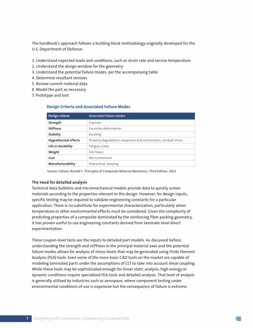
3. Understand the potential failure modes, per the accompanying table
4. Determine resultant stresses
5. Review current material data
6. Model the part as necessary
7. Prototype and test
Design Criteria and Associated Failure Modes
Source: Gibson, Ronald F., Principles of Composite Material Mechanics, Third Edition, 2012
The need for detailed analysis
Technical data bulletins and micromechanical models provide data to quickly screen
materials according to the properties relevant to the design. However, for design inputs,
specific testing may be required to validate engineering constants for a particular
application. There is no substitute for experimental characterization, particularly when
temperature or other environmental effects must be considered. Given the complexity of
predicting properties of a composite dominated by the reinforcing fiber packing geometry,
it has proven useful to use engineering constants derived from laminate-level direct
experimentation.
These coupon-level tests are the inputs to detailed part models. As discussed before,
understanding the strength and stiffness in the principal material axes and the potential
failure modes allows for analysis of stress levels that may be generated using Finite Element
Analysis (FEA) tools. Even some of the more basic CAD tools on the market are capable of
modeling laminated parts under the assumptions of CLT to take into account shear coupling.
While these tools may be sophisticated enough for linear static analysis, high-energy or
dynamic conditions require specialized FEA tools and detailed analysis. That level of analysis
is generally utilized by industries such as aerospace, where component testing under
environmental conditions of use is expensive but the consequence of failure is extreme.
Design criteria Associated failure modes
Strength Fracture
Stiffness Excessive deformation
Stability Buckling
Hygrothermal effects Property degradation, expansion and contractions, residual stress
Life or durability Fatigue, creep
Weight Too heavy
Cost Not economical
Manufacturability Impractical, warping
8 Designing with Composites: Engineering Fundamentals
Even if advanced FEA models are used to optimize design or analyze complex conditions
such as thermally induced strains, the part will need to be built and tested to failure. While
this process is normal for designs on all materials, it becomes even more important in the
design of composite parts due to the number of potential failure modes. Some failure
modes are difficult or impossible to predict using only theoretical constructs.
VI. How Stock Laminate Shapes Can Accelerate the Design and Development Process
Many designers of composites have become accustomed to working with unidirectional
lamina when designing laminates for complex shapes to be produced in a single fabrication
step using a molding process. They would go through the various design stages and
ultimately fabricate a part (such as an airplane wing) in an autoclave.
Before that approach was even available, composite materials have been produced in stock
shapes such as sheets, rods and tubes, then fabricated into the desired geometry. While this
approach does not start with a net shape, it has several advantages.
Those advantages include no need for specialized tooling or molds, which allows for faster
prototyping. Secondly, these composite materials are produced through high-speed,
automated processes, which are designed to ensure a very repeatable and consistent
product in large volumes.
Finally, many of these materials have already been produced and are readily available for
new applications or as a starting point for the design of a new material. This permits use
of established performance anecdotes at the very beginning of the design process. The
complexities of predicting performance of a new composite can be reduced using coupon
data and practical application experience, baseline testing utilizing existing materials, and
analytical models such as those presented in this paper.
The information provided herein is based upon published academic work and anecdotal evidence compiled by Norplex-Micarta. This is not a definitive guide to the analysis or design of composites. To assure the material’s performance is adequate for a specific application, customers should independently verify performance characteristics of interest.
It has proven useful
to use engineering
constants derived
from laminate-
level direct
experimentation.
9 Designing with Composites: Engineering Fundamentals
About Norplex-Micarta
Beginning with Bakelite phenolic resin in the early 20th century, Norplex-Micarta has led the
development of new and advanced thermoset composite materials including its namesake
material, micarta. Norplex-Micarta reliably and consistently develops and supplies quality
materials for some of the most demanding applications around the world.
We work directly and collaboratively with designers to solve complex problems. Decades of
experience developing new composites for industrial, aerospace, power generation, medical
equipment, military and transportation uses has enabled Norplex-Micarta to develop a suite
of standard products that are the basis for our ongoing development work. These standard
products allow designers to establish a performance baseline and familiarize themselves
with the potential of new materials and applications. These initial building blocks are
continuously being augmented with new technologies, allowing designers to be creative in
considering new material solutions to difficult design problems.
Each Norplex-Micarta manufacturing facility has a set of unique capabilities. The company
headquarters, primary design center and manufacturing complex in Postville, Iowa, USA,
processes a variety of resin and substrate combinations in pre-preg, sheet, convolute rolled
tube and molded shape form. A state-of-the-art facility in Changzhou, P.R. China, focuses
on the design, production and fabrication of glass-epoxy materials. Laboratories in both
ISO9000-certified facilities are equipped with sophisticated test equipment to support
development and ongoing verification of materials.
White paper author
Dustin D. Davis
Director of Technology and Business Development
Norplex-Micarta global headquarters
665 Lybrand Street, PO Box 977
Postville, Iowa, USA 52162-0977
800.350.9490
norplex-micarta.com
DesigningWithComposites.com

10 Designing with Composites: Engineering Fundamentals
Bibliography
1 Gibson, R. F. (2012) Principles of Composite Material Mechanics. Third Edition. Boca Raton,
CRC Press, an imprint of Taylor & Francis Group. pp. 57.
2 Gibson, R. F. (2012) Principles of Composite Material Mechanics. Third Edition. Boca Raton,
CRC Press, an imprint of Taylor & Francis Group. pp. 97–113.
3 Agarwal, B. D., Broutman, L. J., & Chandrashekhara, K. (2006) Analysis and Performance of
Fiber Composites. Hoboken, John Wiley & Sons, Inc. pp. 158–160.
4 Gibson, R. F. (2012) Principles of Composite Material Mechanics. Third Edition. Boca Raton,
CRC Press, an imprint of Taylor & Francis Group. pp. 135–137.
5 Gibson, R. F. (2012) Principles of Composite Material Mechanics. Third Edition. Boca Raton,
CRC Press, an imprint of Taylor & Francis Group. pp. 164–169.
6 Gibson, R. F. (2012) Principles of Composite Material Mechanics. Third Edition. Boca Raton,
CRC Press, an imprint of Taylor & Francis Group. pp. 297–298.
7 Gibson, R. F. (2012) Principles of Composite Material Mechanics. Third Edition. Boca Raton,
CRC Press, an imprint of Taylor & Francis Group. pp. 93–94.
8 Department of Defense. (1997) Composites Material Handbook (Vol. 1, Polymer Matrix
Composites Guidelines for Characterization of Structural Materials).