desigo™ rxa non-communicating room controllers rxa21€¦ · · 2015-11-05desigo™ rxa...
TRANSCRIPT

CA2N3881en_02 2012-08-28 Siemens Building Technologies
3881
DESIGO™ RXA
Non-communicating room controllers
RXA20.1RXA21.1RXA22.1
For fan-coil systems
The RXA20.1, RXA21.1 and RXA22.1 room controllers are used for temperature control in individual rooms.
For 2-pipe or 4-pipe fan-coil systems, with or without changeover Control of AC 24 V PWM 1) thermic valve actuators, 3-position AC 24 V valve
and damper actuators, or electric heating coils Volt-free relay contacts for fan control and electric heating coils PI control AC 230 V operating voltage
1) PWM = pulse-width modulated
Use
The RXA20.1, RXA21.1 and RXA22.1 room controllers are optimised for control of fan-coil systems in individual rooms.
They can be used for the following: RXA20.1: Single-speed automatic fan control, thermic valves RXA21.1: 3-speed automatic fan control, thermic or motorised valves RXA22.1: 3-speed automatic fan control, thermic valves
with built-in relay for electric re-heating
For latest prices and delivery to your door visit MyTub Ltd - www.mytub.co.uk - [email protected] 0844 556 1818
2/14
Siemens Non-communicating room controllers CA2N3881en_02 Building Technologies RXA20.1, RXA21.1, RXA22.1 2012-08-28
Functions
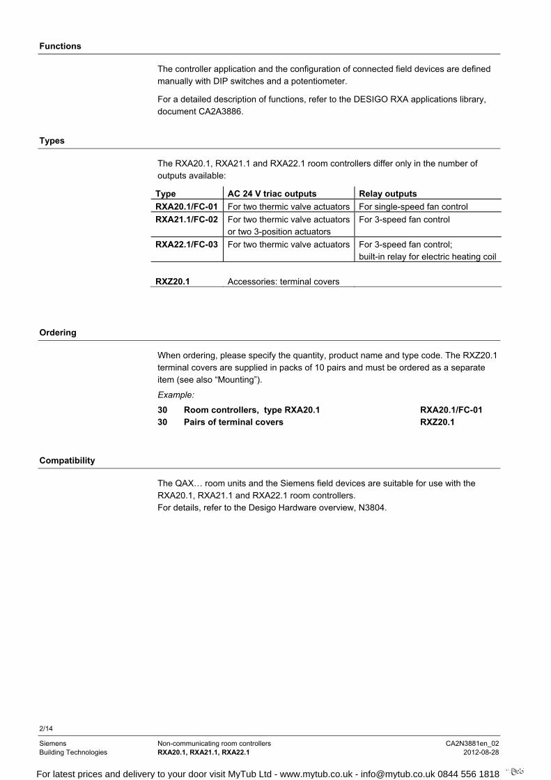
The controller application and the configuration of connected field devices are defined manually with DIP switches and a potentiometer.
For a detailed description of functions, refer to the DESIGO RXA applications library, document CA2A3886.
Types
The RXA20.1, RXA21.1 and RXA22.1 room controllers differ only in the number of outputs available:
Type AC 24 V triac outputs Relay outputs
RXA20.1/FC-01 For two thermic valve actuators For single-speed fan control
RXA21.1/FC-02 For two thermic valve actuators or two 3-position actuators
For 3-speed fan control
RXA22.1/FC-03 For two thermic valve actuators For 3-speed fan control; built-in relay for electric heating coil
RXZ20.1
Accessories: terminal covers
Ordering
When ordering, please specify the quantity, product name and type code. The RXZ20.1 terminal covers are supplied in packs of 10 pairs and must be ordered as a separate item (see also “Mounting”).
Example:
30 Room controllers, type RXA20.1 RXA20.1/FC-01 30 Pairs of terminal covers RXZ20.1
Compatibility
The QAX… room units and the Siemens field devices are suitable for use with the RXA20.1, RXA21.1 and RXA22.1 room controllers. For details, refer to the Desigo Hardware overview, N3804.
For latest prices and delivery to your door visit MyTub Ltd - www.mytub.co.uk - [email protected] 0844 556 1818

3/14
Siemens Non-communicating room controllers CA2N3881en_02 Building Technologies RXA20.1, RXA21.1, RXA22.1 2012-08-28
Design
The RXA20.1, RXA21.1 and RXA22.1 room controllers consist of a housing base, a housing cover and the printed circuit board. The printed circuit board incorporates the connection terminals and the DIP switches used for configuration. The controllers also have a potentiometer for setpoint adjustment and testing, and a Service LED with different flashing patterns to indicate operational status and test states.
Connection terminals
Housing cover
Connection terminals
00608
Cable restraints DIP switches Housing base
Service LED Potentiometer
Terminal covers (RXZ20.1) are available as an option, to protect the connection terminals from physical contact and dirt. The Service LED and the potentiometer remain visible even with the terminal covers fitted. The potentiometer can be operated with a screwdriver. The cable is connected to the room controller by breaking out the perforated cable entry guide.
70200
Removing the terminal cover
Protection standard
Temperature range
(0 … 50 °C)
Serial No.
Test date, series(Z, A, B, C…)
Observe notes
in this document
Programmed application
Location
3881Z01
090601A 513
Terminal cover
Label (example for RXA21.1)
For latest prices and delivery to your door visit MyTub Ltd - www.mytub.co.uk - [email protected] 0844 556 1818
4/14
Siemens Non-communicating room controllers CA2N3881en_02 Building Technologies RXA20.1, RXA21.1, RXA22.1 2012-08-28
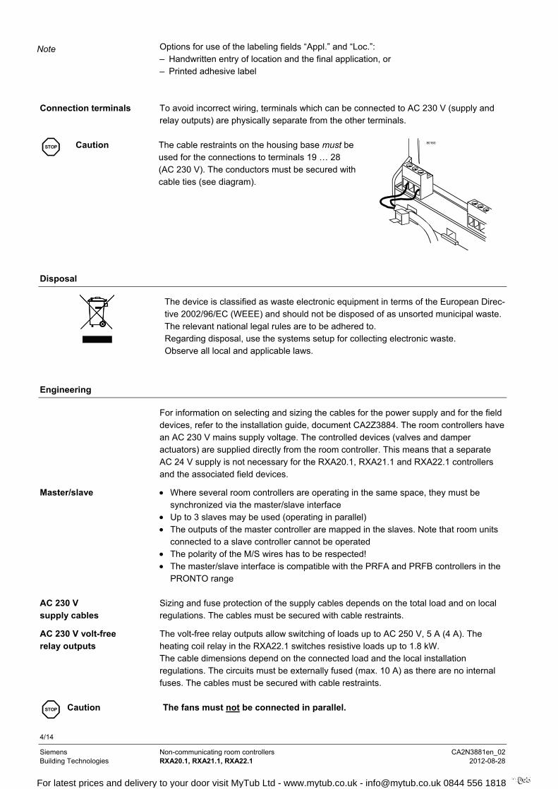
Options for use of the labeling fields “Appl.” and “Loc.”: – Handwritten entry of location and the final application, or – Printed adhesive label To avoid incorrect wiring, terminals which can be connected to AC 230 V (supply and relay outputs) are physically separate from the other terminals.
STOP
Caution
The cable restraints on the housing base must be used for the connections to terminals 19 … 28 (AC 230 V). The conductors must be secured with cable ties (see diagram).
80160
Disposal
The device is classified as waste electronic equipment in terms of the European Direc-tive 2002/96/EC (WEEE) and should not be disposed of as unsorted municipal waste. The relevant national legal rules are to be adhered to. Regarding disposal, use the systems setup for collecting electronic waste. Observe all local and applicable laws.
Engineering
For information on selecting and sizing the cables for the power supply and for the field devices, refer to the installation guide, document CA2Z3884. The room controllers have an AC 230 V mains supply voltage. The controlled devices (valves and damper actuators) are supplied directly from the room controller. This means that a separate AC 24 V supply is not necessary for the RXA20.1, RXA21.1 and RXA22.1 controllers and the associated field devices.
Where several room controllers are operating in the same space, they must be synchronized via the master/slave interface
Up to 3 slaves may be used (operating in parallel) The outputs of the master controller are mapped in the slaves. Note that room units
connected to a slave controller cannot be operated The polarity of the M/S wires has to be respected! The master/slave interface is compatible with the PRFA and PRFB controllers in the
PRONTO range Sizing and fuse protection of the supply cables depends on the total load and on local regulations. The cables must be secured with cable restraints.
The volt-free relay outputs allow switching of loads up to AC 250 V, 5 A (4 A). The heating coil relay in the RXA22.1 switches resistive loads up to 1.8 kW. The cable dimensions depend on the connected load and the local installation regulations. The circuits must be externally fused (max. 10 A) as there are no internal fuses. The cables must be secured with cable restraints.
STOP
Caution The fans must not be connected in parallel.
Note
Connection terminals
Master/slave
AC 230 V supply cables
AC 230 V volt-free relay outputs
For latest prices and delivery to your door visit MyTub Ltd - www.mytub.co.uk - [email protected] 0844 556 1818
5/14
Siemens Non-communicating room controllers CA2N3881en_02 Building Technologies RXA20.1, RXA21.1, RXA22.1 2012-08-28
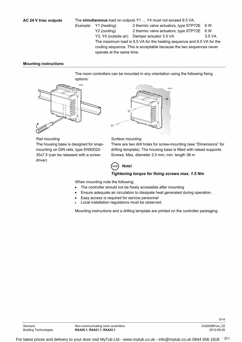
The simultaneous load on outputs Y1 … Y4 must not exceed 9.5 VA. Example: Y1 (heating) 2 thermic valve actuators, type STP72E 6 W Y2 (cooling) 2 thermic valve actuators, type STP72E 6 W Y3, Y4 (outside air) Damper actuator 3.5 VA 3.5 VA
The maximum load is 9.5 VA for the heating sequence and 9.5 VA for the cooling sequence. This is acceptable because the two sequences never operate at the same time.
Mounting instructions
The room controllers can be mounted in any orientation using the following fixing options:
00609
00610
Rail mounting The housing base is designed for snap-mounting on DIN rails, type EN50022-35x7.5 (can be released with a screw-driver)
Surface mounting There are two drill holes for screw-mounting (see “Dimensions” for drilling template). The housing base is fitted with raised supports. Screws: Max. diameter 3.5 mm, min. length 38 m
STOP Note!
Tightening torque for fixing screws max. 1.5 Nm
When mounting note the following: The controller should not be freely accessible after mounting Ensure adequate air circulation to dissipate heat generated during operation. Easy access is required for service personnel Local installation regulations must be observed.
Mounting instructions and a drilling template are printed on the controller packaging.
AC 24 V triac outputs
For latest prices and delivery to your door visit MyTub Ltd - www.mytub.co.uk - [email protected] 0844 556 1818

6/14
Siemens Non-communicating room controllers CA2N3881en_02 Building Technologies RXA20.1, RXA21.1, RXA22.1 2012-08-28
Commissioning
The controller application and the configuration of the connected field devices are defined manually with DIP switches and the potentiometer. The Service LED provides information on power up and operational status.
There is no special test for checking that the connected field devices match the DIP switch settings. Depending on the application, if the controller has insufficient information it switches to "Idle" mode (all outputs at zero) and the LED remains on continuously.
For details refer to the applications library CA2A3886.
STOP
Caution
In the event of a long-term short circuit or overload, the thermal fuse in the transformer may trip. The controller must then be replaced.
There is no protection against accidental connection with 230 V on the AC 24 V side.
Technical data
Power supply Operating voltage AC 230 V ± 10 % Rated voltage AC 230 V Frequency 50/60 Hz Power consumption with
output field devices connected Max. 12 VA
Internal fuse Thermal, non-resetting Operating data Control algorithm PI Inputs Signal inputs D1 … D3 (for volt-free contacts) Quantity 3 Contact voltage DC 16 V Contact current DC 8 mA Contact transfer resistance Max. 100 Contact insulation resistance Min. 50 k Not suitable for pulse control Measured value inputs B1 and X2 Type of signal is programmable (DIP switch) LG-Ni 1000 temperature sensor,
setpoint adjuster or 0 … 10 V signal Temperature sensor LG-Ni 1000 Measuring range 0 ... 50 °C Sensor current 2.3 mA Resolution 0.2 K Measuring error at 25 °C sensor temp. (without
cable) Max. 0.2 K
Setpoint adjuster BSG21.5 Reset range +/– 3K Setpoint reset signal 0 … 10 V RKN-S for summer/winter compensation See data sheet CA2N3389 (No longer available!) Outputs AC24 V triac outputs , Y1 … Y4 Quantity 2 (RXA20.1, RXA22.1)
4 (RXA21.1) Output voltage (SELV, not earthed) AC 24 V ON/OFF, PWM or 3-position
(depending on application) Output current Max. 0.5 A Total nominal load
(at both outputs simultaneously) Max. 9.5 VA (e.g. 2 thermic valves, type STE72 per heating and cooling sequence + 1 damper actuator 3.5 VA)
For latest prices and delivery to your door visit MyTub Ltd - www.mytub.co.uk - [email protected] 0844 556 1818
7/14
Siemens Non-communicating room controllers CA2N3881en_02 Building Technologies RXA20.1, RXA21.1, RXA22.1 2012-08-28
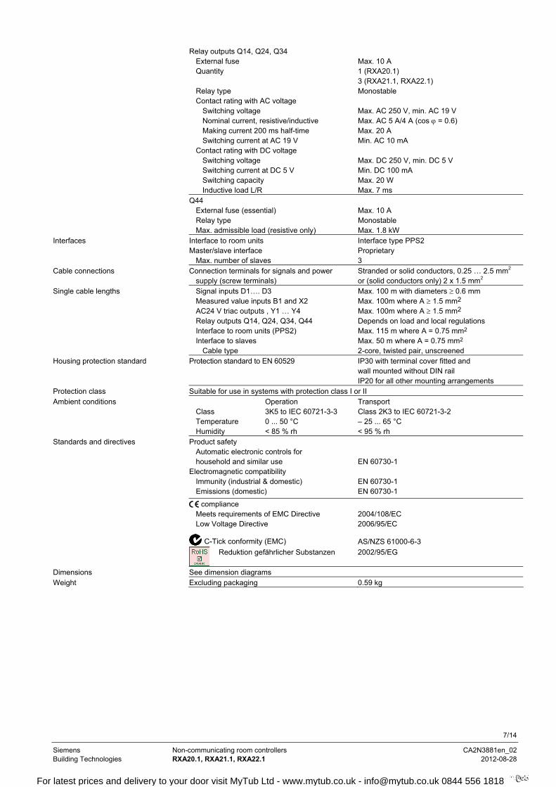
Relay outputs Q14, Q24, Q34 External fuse Max. 10 A Quantity 1 (RXA20.1)
3 (RXA21.1, RXA22.1) Relay type Monostable Contact rating with AC voltage Switching voltage Max. AC 250 V, min. AC 19 V Nominal current, resistive/inductive Max. AC 5 A/4 A (cos = 0.6) Making current 200 ms half-time Max. 20 A Switching current at AC 19 V Min. AC 10 mA Contact rating with DC voltage Switching voltage Max. DC 250 V, min. DC 5 V Switching current at DC 5 V Min. DC 100 mA Switching capacity Max. 20 W Inductive load L/R Max. 7 ms Q44 External fuse (essential) Max. 10 A Relay type Monostable Max. admissible load (resistive only) Max. 1.8 kW Interfaces Interface to room units Interface type PPS2 Master/slave interface Proprietary Max. number of slaves 3 Cable connections Connection terminals for signals and power
supply (screw terminals) Stranded or solid conductors, 0.25 … 2.5 mm2
or (solid conductors only) 2 x 1.5 mm2 Single cable lengths Signal inputs D1…. D3 Max. 100 m with diameters 0.6 mm Measured value inputs B1 and X2 Max. 100m where A 1.5 mm2 AC24 V triac outputs , Y1 … Y4 Max. 100m where A 1.5 mm2 Relay outputs Q14, Q24, Q34, Q44 Depends on load and local regulations Interface to room units (PPS2) Max. 115 m where A = 0.75 mm2 Interface to slaves Max. 50 m where A = 0.75 mm2 Cable type 2-core, twisted pair, unscreened Housing protection standard Protection standard to EN 60529 IP30 with terminal cover fitted and
wall mounted without DIN rail IP20 for all other mounting arrangements Protection class Suitable for use in systems with protection class I or II Ambient conditions Operation Transport Class 3K5 to IEC 60721-3-3 Class 2K3 to IEC 60721-3-2 Temperature 0 ... 50 °C – 25 ... 65 °C Humidity < 85 % rh < 95 % rh Standards and directives Product safety Automatic electronic controls for
household and similar use EN 60730-1
Electromagnetic compatibility Immunity (industrial & domestic) EN 60730-1
Emissions (domestic) EN 60730-1
compliance Meets requirements of EMC Directive 2004/108/EC
Low Voltage Directive 2006/95/EC
C-Tick conformity (EMC) AS/NZS 61000-6-3
Reduktion gefährlicher Substanzen 2002/95/EG
Dimensions See dimension diagrams Weight Excluding packaging 0.59 kg
For latest prices and delivery to your door visit MyTub Ltd - www.mytub.co.uk - [email protected] 0844 556 1818
8/14
Siemens Non-communicating room controllers CA2N3881en_02 Building Technologies RXA20.1, RXA21.1, RXA22.1 2012-08-28
Connection terminals and operator controls
00600 a
1 2 3 4 5 6 7 8 10
M D1
GN
D
D2
Y1
G Y2
B1
12
PPS2
T
19 21 25 26
N L Q1
3
Q1
4
N
5(4) A
14 15 16
CP
-
CP
+
M/S
9
X2
D3
T
0...10 V
5 6 7 84321
ON DIP
9 10
S1...10
R1
21
L
19
AC 230 V
11 12 13
G
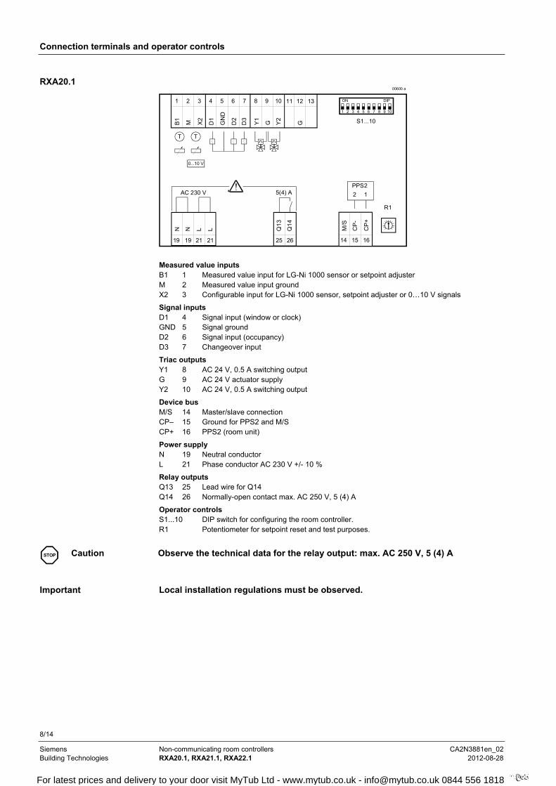
Measured value inputs B1 1 Measured value input for LG-Ni 1000 sensor or setpoint adjuster M 2 Measured value input ground X2 3 Configurable input for LG-Ni 1000 sensor, setpoint adjuster or 0…10 V signals
Signal inputs D1 4 Signal input (window or clock) GND 5 Signal ground D2 6 Signal input (occupancy) D3 7 Changeover input
Triac outputs Y1 8 AC 24 V, 0.5 A switching output G 9 AC 24 V actuator supply Y2 10 AC 24 V, 0.5 A switching output
Device bus M/S 14 Master/slave connection CP– 15 Ground for PPS2 and M/S CP+ 16 PPS2 (room unit)
Power supply N 19 Neutral conductor L 21 Phase conductor AC 230 V +/- 10 %
Relay outputs Q13 25 Lead wire for Q14 Q14 26 Normally-open contact max. AC 250 V, 5 (4) A
Operator controls S1...10 DIP switch for configuring the room controller. R1 Potentiometer for setpoint reset and test purposes.
STOP
Caution Observe the technical data for the relay output: max. AC 250 V, 5 (4) A
Local installation regulations must be observed.
RXA20.1
Important
For latest prices and delivery to your door visit MyTub Ltd - www.mytub.co.uk - [email protected] 0844 556 1818
9/14
Siemens Non-communicating room controllers CA2N3881en_02 Building Technologies RXA20.1, RXA21.1, RXA22.1 2012-08-28
Connection terminals and operator controls
00601 a
1 2 3 4 5 6 7 8 10 11 12 13
M D1
GN
D
D2
Y1
G Y2
B1
12
QAX...
T
M
25 26 27 28
Q1
3
Q1
4Y
3
G Y4
M
Q2
4
Q3
4
5(4) A
14 15 16
CP
-
CP
+
M/S
9
X2
D3
T
0...10 V
5 6 7 84321
ON DIP
9 10 11 12
S 1...12
R1
19 21
N LN
21
L
19
AC 230 V
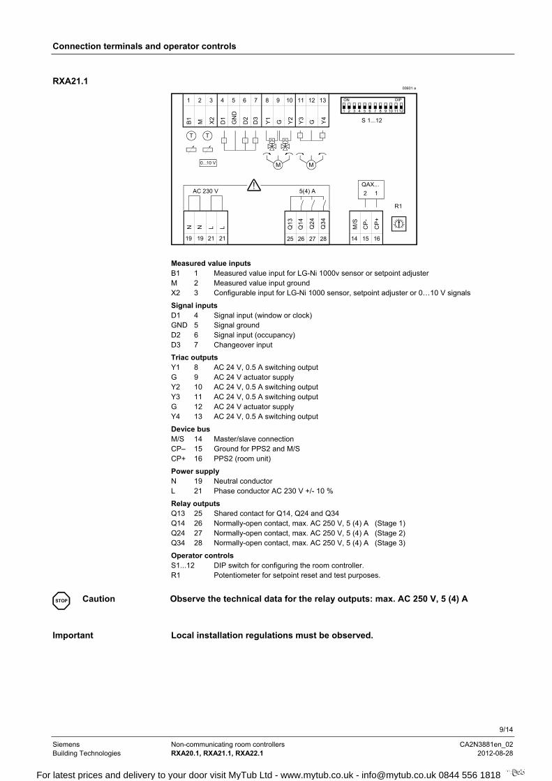
Measured value inputs B1 1 Measured value input for LG-Ni 1000v sensor or setpoint adjuster M 2 Measured value input ground X2 3 Configurable input for LG-Ni 1000 sensor, setpoint adjuster or 0…10 V signals
Signal inputs D1 4 Signal input (window or clock) GND 5 Signal ground D2 6 Signal input (occupancy) D3 7 Changeover input
Triac outputs Y1 8 AC 24 V, 0.5 A switching output G 9 AC 24 V actuator supply Y2 10 AC 24 V, 0.5 A switching output Y3 11 AC 24 V, 0.5 A switching output G 12 AC 24 V actuator supply Y4 13 AC 24 V, 0.5 A switching output
Device bus M/S 14 Master/slave connection CP– 15 Ground for PPS2 and M/S CP+ 16 PPS2 (room unit)
Power supply N 19 Neutral conductor L 21 Phase conductor AC 230 V +/- 10 %
Relay outputs Q13 25 Shared contact for Q14, Q24 and Q34 Q14 26 Normally-open contact, max. AC 250 V, 5 (4) A (Stage 1) Q24 27 Normally-open contact, max. AC 250 V, 5 (4) A (Stage 2) Q34 28 Normally-open contact, max. AC 250 V, 5 (4) A (Stage 3)
Operator controls S1...12 DIP switch for configuring the room controller. R1 Potentiometer for setpoint reset and test purposes.
STOP
Caution Observe the technical data for the relay outputs: max. AC 250 V, 5 (4) A
Local installation regulations must be observed.
RXA21.1
Important
For latest prices and delivery to your door visit MyTub Ltd - www.mytub.co.uk - [email protected] 0844 556 1818

10/14
Siemens Non-communicating room controllers CA2N3881en_02 Building Technologies RXA20.1, RXA21.1, RXA22.1 2012-08-28
Connection terminals and operator controls
3881Z02
1 2 3 4 5 6 7 8 10
M D1
GN
D
D2
Y1
G Y2
B1
12
QAX...
T
25 26 27 28
Q13
Q14
Q24
Q34
5(4) A
14 15 16
CP
-
CP
+
M/S
9
X2
D3
T
0...10 V
R1
22 23 24N
.C.
Q44
10 A
5 6 7 84321
ON DIP
9 10
S1...10
19 21
N LN
21
L
19
AC 230 V
11 12 13
G
Q43
Measured value inputs B1 1 Measured value input for LG-Ni 1000 sensor or setpoint adjuster M 2 Measured value input ground X2 3 Configurable input for LG-Ni 1000 sensor, setpoint adjuster or 0…10 V signals
Signal inputs D1 4 Signal input (window or clock) GND 5 Signal ground D2 6 Signal input (occupancy) D3 7 Changeover input
Triac outputs Y1 8 AC 24 V, 0.5 A switching output G 9 AC 24 V actuator supply Y2 10 AC 24 V, 0.5 A switching output
Device bus M/S 14 Master/slave connection CP– 15 Ground for PPS2 and M/S CP+ 16 PPS2 (room unit)
Power supply N 19 Neutral conductor L 21 Phase conductor AC 230 V +/- 10 %
Relay outputs Q13 25 Shared contact for Q14, Q24 and Q34 Q14 26 Normally-open contact, max. AC 250 V, 5 (4) A (Stage 1) Q24 27 Normally-open contact, max. AC 250 V, 5 (4) A (Stage 2) Q34 28 Normally-open contact, max. AC 250 V, 5 (4) A (Stage 3) N.C. 22 Not connected Q43 23 Lead wire for Q44 Q44 21 N/O contact AC max. 250 V, 10 A...(electric heating coil)
Operator controls S1...10 DIP switch for configuring the room controller. R1 Potentiometer for setpoint reset and test purposes.
STOP
Caution Observe the technical data for the relay outputs:
max. AC 250 V, 5 (4) A or 10 A Local installation regulations must be observed.
RXA22.1
For latest prices and delivery to your door visit MyTub Ltd - www.mytub.co.uk - [email protected] 0844 556 1818

11/14
Siemens Non-communicating room controllers CA2N3881en_02 Building Technologies RXA20.1, RXA21.1, RXA22.1 2012-08-28
Connection diagrams
1
2
4
5
6
11
12
13
15
16
M
D1
GND
D2
CP–
CP+
B1
Y3
G
Y4
19
21
N
L
N
25
26
27
28
Q13
Q14
Q24
Q34
2
3
1
N
N
LAC 230 V
1
N
L
Q2 Q1
B3PPS2
Y1
Y2
D1
D2
T B1
GL Y3.1M
GL Y1.1M
N1 3881Z03
N.C.
Q44
23
22
24
L
N
Q4
Y3.2
3X2 B2T
8
9
10
Y1
G
Y2
D3 7 D3
B2.1 X2.2
14M/S
RXA N2...N4
0...10 V
B1.1
14
15
M
21L
19
F1Q43
N1 RXA20.1, RXA21.1, RXA22.1 N2...N4 Max. 3 slave controllers B1, B2 LG-Ni 1000 temperature sensor B1.1, B2.1 Setpoint adjuster X2.2 0…10 V signal (summer/winter compensation) B3 QAX… room unit D1, D2 Volt-free contacts (window contact, occupancy sensor, central time switch etc.) D3 Changeover signal Y1, Y2 AC 24 V thermic valve actuators Y1.1, Y3.1 Valve actuator, AC 24 V, 3-position (RXA21.1 only) Y3.2 Damper actuator with spring return Q1 Single-speed fan Q2 3-speed fan Q4 Electric heating coil F1 External fuse
Twisted pair
Connecting the field devices, room units and supply voltage
For latest prices and delivery to your door visit MyTub Ltd - www.mytub.co.uk - [email protected] 0844 556 1818
12/14
Siemens Non-communicating room controllers CA2N3881en_02 Building Technologies RXA20.1, RXA21.1, RXA22.1 2012-08-28
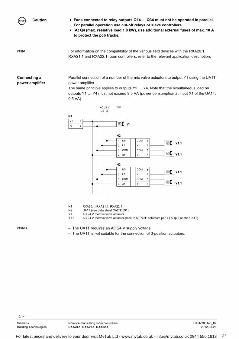
STOP
Caution Fans connected to relay outputs Q14 … Q34 must not be operated in parallel.
For parallel operation use cut-off relays or slave controllers. At Q4 (max. resistive load 1.8 kW), use additional external fuses of max. 10 A
to protect the pcb tracks.
For information on the compatibility of the various field devices with the RXA20.1, RXA21.1 and RXA22.1 room controllers, refer to the relevant application description. Parallel connection of a number of thermic valve actuators to output Y1 using the UA1T power amplifier. The same principle applies to outputs Y2 … Y4. Note that the simultaneous load on outputs Y1 … Y4 must not exceed 9.5 VA (power consumption at input X1 of the UA1T: 0.5 VA)
1
2
3
4
NS
LS
COM
X1
AC 24 V
Y1.1
Y1.1
70206
6
7
Y1
GY1
G0 G
8
7
6
5
COM
Y1
COM
Y1
N2
1
2
3
4
NS
LS
COM
X1
Y1.1
Y1.1
8
7
6
5
COM
Y1
COM
Y1
N2
N1
N1 RXA20.1, RXA21.1, RXA22.1 N2 UA1T (see data sheet CA2N3591) Y1 AC 24 V thermic valve actuator Y1.1 AC 24 V thermic valve actuator (max. 2 STP72E actuators per Y1 output on the UA1T)
– The UA1T requires an AC 24 V supply voltage – The UA1T is not suitable for the connection of 3-position actuators.
Note
Connecting a power amplifier
Notes
For latest prices and delivery to your door visit MyTub Ltd - www.mytub.co.uk - [email protected] 0844 556 1818
13/14
Siemens Non-communicating room controllers CA2N3881en_02 Building Technologies RXA20.1, RXA21.1, RXA22.1 2012-08-28
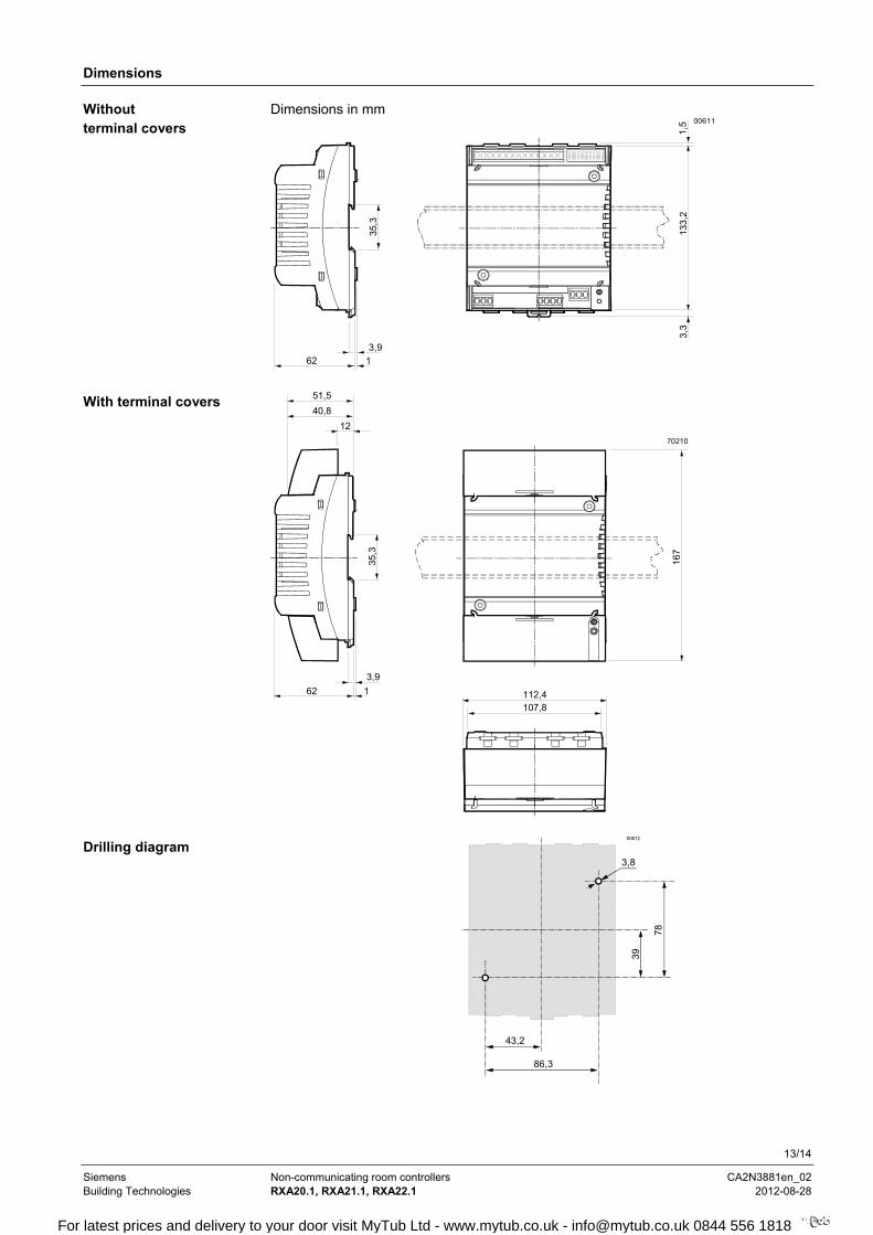
Dimensions
Dimensions in mm
62 1
3,9
35,3
133,
2
00611
3,3
1,5
62 1
3,9
35,3
167
112,4107,8
70210
51,5
40,8
12
78
39
86,3
43,2
3,8
00612
Without terminal covers
With terminal covers
Drilling diagram
For latest prices and delivery to your door visit MyTub Ltd - www.mytub.co.uk - [email protected] 0844 556 1818

14/14
Siemens Non-communicating room controllers CA2N3881en_02 Building Technologies RXA20.1, RXA21.1, RXA22.1 2012-08-28
2001 - 2012 Siemens Building Technologies AG Subject to technical alterations
For latest prices and delivery to your door visit MyTub Ltd - www.mytub.co.uk - [email protected] 0844 556 1818