detailed instructions for use of glass ceramic …
TRANSCRIPT
www.gorenje.com
DETAILED INSTRUCTIONS FOR USE OF GLASS CERAMIC BUILT-IN INDUCTION COOKING HOB
GB IE MT

We thank you for your trust and the purchase of our appliance.
This detailed instruction manual is supplied to make the use of this product easier. The instructions should allow you to learn about your new appliance as quickly as possible.
Make sure you have received an undamaged appliance. If you do find transport damage, please contact the seller from which you purchased the appliance, or the regional warehouse from which it was supplied. The telephone number can be found on the invoice or on the delivery note.
Instructions for use are also available at our website:
www.gorenje.com / < http://www. gorenje.com />
Important information
Tip, note
3
718
03
1
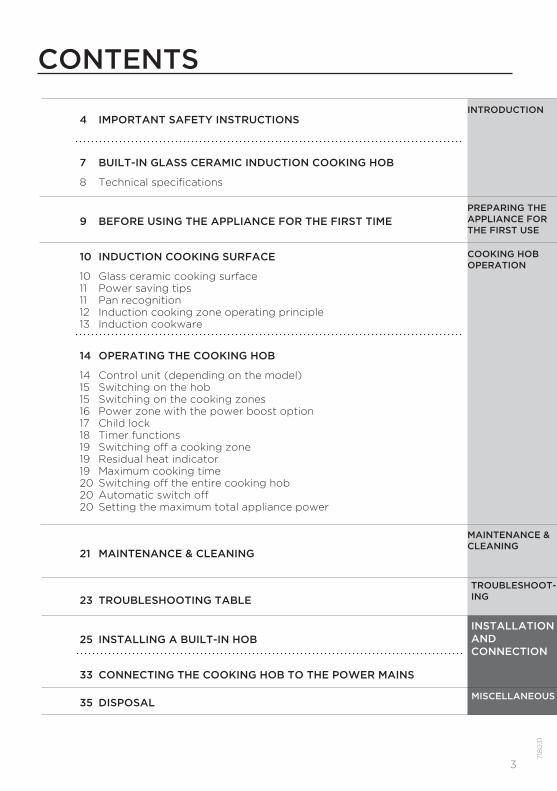
4 IMPORTANT SAFETY INSTRUCTIONS
7 BUILT-IN GLASS CERAMIC INDUCTION COOKING HOB
8 Technical specifications
9 BEFORE USING THE APPLIANCE FOR THE FIRST TIME
10 INDUCTION COOKING SURFACE
10 Glass ceramic cooking surface11 Power saving tips11 Pan recognition12 Induction cooking zone operating principle13 Induction cookware
14 OPERATING THE COOKING HOB
14 Control unit (depending on the model)15 Switching on the hob15 Switching on the cooking zones16 Power zone with the power boost option17 Child lock 18 Timer functions19 Switching off a cooking zone19 Residual heat indicator19 Maximum cooking time20 Switching off the entire cooking hob20 Automatic switch off20 Setting the maximum total appliance power
21 MAINTENANCE & CLEANING
23 TROUBLESHOOTING TABLE
25 INSTALLING A BUILT-IN HOB
33 CONNECTING THE COOKING HOB TO THE POWER MAINS
35 DISPOSAL
INTRODUCTION
PREPARING THE APPLIANCE FOR THE FIRST USE
TROUBLESHOOT-ING
MISCELLANEOUS
COOKING HOB OPERATION
MAINTENANCE & CLEANING
INSTALLATION AND CONNECTION
CONTENTS
4
7180
31
IMPORTANT SAFETY INSTRUCTIONSCAREFULLY READ THE INSTRUCTIONS AND SAVE THEM FOR FUTURE REFERENCE.
This appliance can be used by children aged from 8 years and above and persons with reduced physical, sensory or mental capabilities or lack of experience and knowledge if they have been given supervision or instruction concerning use of the appliance in a safe way and understand the hazards involved. Children shall not play with the appliance. Cleaning and user maintenance shall not be made by children without supervision.
WARNING: The appliance and its accessible parts become hot during use. Care should be taken to avoid touching heating elements. Children less than 8 years of age shall be kept away unless continuously supervised.
Danger of fire: Do not store items on the cooking surfaces.
CAUTION: The cooking process has to be supervised. A short term cooking process has to be supervised continuously.
WARNING: Unattended cooking on a hob with fat or oil can be dangerous and may result in fire. NEVER try to extinguish a fire with water, but switch off the appliance and then cover flame e.g. with a lid or a fire blanket.
WARNING: If the surface is cracked, switch off the appliance to avoid the possibility of electric shock. Switch off all cooking zones using their respective controls and
5
718
03
1
remove the fuse or trip the main circuit breaker so that the appliance is fully isolated from the power mains.
Means for disconnection must be incorporated in the fixed wiring in accordance with the wiring rules.
Do not place objects like knives, forks, spoons, or lids on the induction cooking zone as they can become very hot.
Do not use steam cleaners or high pressure cleaners to clean the appliances as this may result in an electric shock.
The appliance is not intended to be controlled with external timers or special control systems.
WARNING: Use only hob guards designed by the manufacturer of the cooking appliance or indicated by the manufacturer of the appliance in the instructions for use as suitable or hob guards incorporated in the appliance. The use of inappropriate guards can cause accidents.
After use, switch off the hob element by its control and do not rely on the pan detector.

6
7180
31
The appliance is intended for household use. Do not use it for any other purpose, e.g. for room heating.
The appliance may only be connected to the power mains by an authorized service technician or expert. Tampering with the appliance or non-professional repair thereof may result in risk of severe injury or damage to the product.
If another electrical appliance is connected to an AC power socket near the appliance, make sure the power cord does not come into contact with hot cooking zones.
If the power cord is damaged, it should be replaced by the manufacturer or an authorized service technician, in order to avoid hazard.
Using the glass ceramic hob as a storage area may result in scratches or other damage to it. Never heat food in aluminium foil or in plastic containers on the cooking hob. Such foil or containers may melt which can result in a fire or damage to the cooking hob.
Do not store temperature-sensitive items underneath the appliance, such as cleaners or detergents, spray cans etc.
Eventual mismatches in colour shades between different appliances or components within a single design line may oAccur due to various factors, such as different angles under which the appliances are observed, different coloured backgrounds, materials, and room illumination.
Carefully read the instructions for use before connectingthe appliance. Repairs or any warranty claims resulting fromincorrect connection or use of the appliance shall not be coveredby the warranty.
7
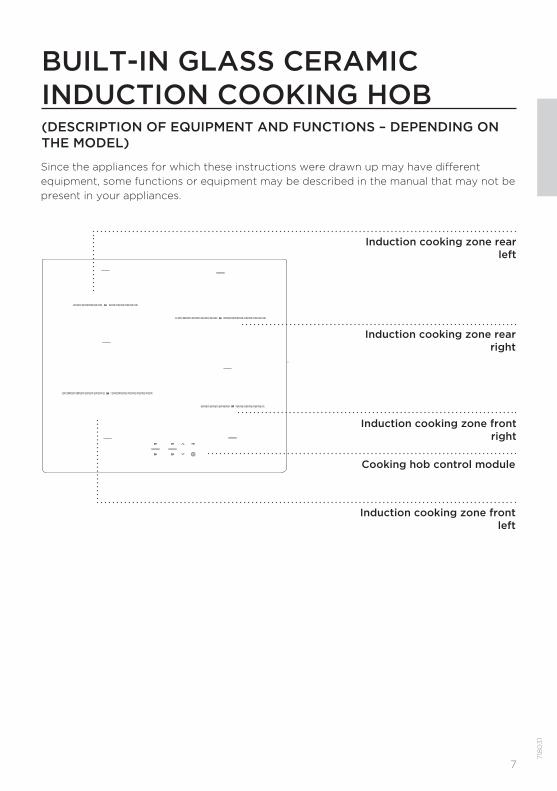
BUILT-IN GLASS CERAMIC INDUCTION COOKING HOB(DESCRIPTION OF EQUIPMENT AND FUNCTIONS – DEPENDING ON THE MODEL)
Induction cooking zone rear left
Induction cooking zone rear right
Induction cooking zone front right
Induction cooking zone front left
Cooking hob control module
718
03
1
Since the appliances for which these instructions were drawn up may have different equipment, some functions or equipment may be described in the manual that may not be present in your appliances.
8
7180
31
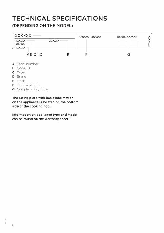
TECHNICAL SPECIFICATIONS(DEPENDING ON THE MODEL)
The rating plate with basic information on the appliance is located on the bottom side of the cooking hob.
Information on appliance type and model can be found on the warranty sheet.
A Serial numberB Code/IDC TypeD BrandE ModelF Technical dataG Compliance symbols

9
718
03
1
BEFORE USING THE APPLIANCE FOR THE FIRST TIMEIf your hob has a glass ceramic surface, clean it with a damp cloth and some washing-up liquid. Do not use aggressive cleaners, such as abrasive cleaners that could cause scratches, abrasive dishwashing sponges, or stain removers.
During initial use, characteristic "new appliance smell" may appear; it will gradually disappear.

10
7180
31
INDUCTION COOKING SURFACE GLASS CERAMIC COOKING SURFACE- The hob is resistant to temperature changes.- The hob is also impact-resistant.- Using the glass ceramic hob as a storage area may result in scratches or other damage to it.- Do not use the glass ceramic hob if it is cracked or broken. If a sharp object falls on the hob,
the hob may break. The consequences of such occurrence may be visible immediately or only after a while. If any visible crack appears in the hob, immediately cut off the power supply to the appliance.
- Make sure the cooking zone and the cookware bottom is clean and dry. This will allow better conduction of heat and prevent any damage to the heating surface. Do not place empty cookware on the cooking zone.
- The cooking zone may be damaged if you place an empty pan onto it. Before placing a pan onto the cooking zone, wipe the pan bottom dry to allow conduction of heat.
COOKING POWER LEVELS
Cooking zone heat power can be set to ten different levels. The table lists some examples of use for each level.
Level Purpose
0 Switched off , using the residual heat
1 - 2 Keeping the food warm, slow cooking of smaller amounts (lowest setting)
3 Slow cooking (follow-up cooking after the initial power boost)
4 - 5 Slow cooking (follow-up cooking) of large amounts, pan-roasting of larger chunks
6 Searing and browning
7 - 8 Searing
9 Cooking of large amounts, searing
P Power boost setting for start of the cooking process; also suitable for very large amounts of food

11
718
03
1
POWER SAVING TIPS- When purchasing cookware, note that the diameter indicated on the pan usually pertains to
the upper edge or the lid, which is normally larger than the diameter of the pan bottom. - If a dish takes a long time to cook, use a pressure cooker. Make sure there is always suffi cient
liquid in the pressure cooker. If an empty cooker is placed on the cooking hob, it may overheat which in turn may lead to damage to both the pot and the cooking zone.
- Whenever possible, close the pot or pan with a suitably sized lid. Use cookware that fi ts the amount of food you are cooking. Cooking in a large partly full pot will consume much more energy.
PAN RECOGNITION- Even if there is no pot or pan on the cooking zone or if the pan used
has a diameter that is smaller than the diameter of the cooking zone, there will be no losses of energy.
- “If the pan is much smaller than the cooking zone, there is a possibility that it will not be recognized by the cooking zone. When the cooking zone is activated, the sign and the selected power level will fl ash alternately on the cooking power display.If a suitable pan is placed on the induction cooking zone within the next minute, the hob will recognize it and switch on with the selected cooking power. As soon as the pan is removed from the cooking zone, the power supply is cut off .”
- If a smaller pan or pot is placed on the cooking zone and it is recognized, the hob will only use as much power as necessary given the pan size.
12
7180
31
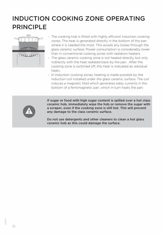
If sugar or food with high sugar content is spilled over a hot class ceramic hob, immediately wipe the hob or remove the sugar with a scraper, even if the cooking zone is still hot. This will prevent any damage to the class ceramic surface.
Do not use detergents and other cleaners to clean a hot glass ceramic hob as this could damage the surface.
- The cooking hob is fi tted with highly effi cient induction cooking zones. The heat is generated directly in the bottom of the pan where it is needed the most. This avoids any losses through the glass ceramic surface. Power consumption is considerably lower than in conventional cooking zones with radiation heaters.
- The glass ceramic cooking zone is not heated directly, but only indirectly with the heat radiated back by the pan. After the cooking zone is switched off , this heat is indicated as »residual heat«.
- In induction cooking zones, heating is made possible by the induction coil installed under the glass ceramic surface. The coil induces a magnetic fi eld which generates eddy currents in the bottom of a ferromagnetic pan, which in turn heats the pan.
INDUCTION COOKING ZONE OPERATING PRINCIPLE
13
718
03
1
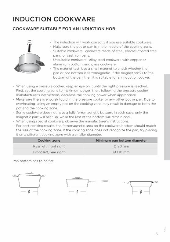
Ø Ø Ø
- The induction will work correctly if you use suitable cookware.- Make sure the pot or pan is in the middle of the cooking zone.- Suitable cookware: cookware made of steel, enamel-coated steel
pans, or cast iron pans.- Unsuitable cookware: alloy steel cookware with copper or
aluminium bottom, and glass cookware.- The magnet test: Use a small magnet to check whether the
pan or pot bottom is ferromagnetic. If the magnet sticks to the bottom of the pan, then it is suitable for an induction cooker.
- When using a pressure cooker, keep an eye on it until the right pressure is reached. First, set the cooking zone to maximum power; then, following the pressure cooker manufacturer's instructions, decrease the cooking power when appropriate.
- Make sure there is enough liquid in the pressure cooker or any other pot or pan. Due to overheating, using an empty pot on the cooking zone may result in damage to both the pot and the cooking zone.
- Some cookware does not have a fully ferromagnetic bottom. In such case, only the magnetic part will heat up, while the rest of the bottom will remain cool.
- When using special cookware, observe the manufacturer's instructions.- For best cooking results, the ferromagnetic area on the cookware bottom should match
the size of the cooking zone. If the cooking zone does not recognize the pan, try placing it on a diff erent cooking zone with a smaller diameter.
Cooking zone Minimum pan bottom diameter
Rear left, front right Ø 90 mm
Front left, rear right Ø 130 mm
Pan bottom has to be flat.
INDUCTION COOKWARECOOKWARE SUITABLE FOR AN INDUCTION HOB
14
7180
31
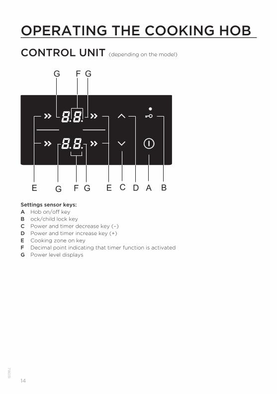
OPERATING THE COOKING HOBCONTROL UNIT (depending on the model)
A BDEE FG G
G GF
C
Settings sensor keys:A Hob on/off keyB ock/child lock keyC Power and timer decrease key (–)D Power and timer increase key (+)E Cooking zone on keyF Decimal point indicating that timer function is activatedG Power level displays
15
718
03
1
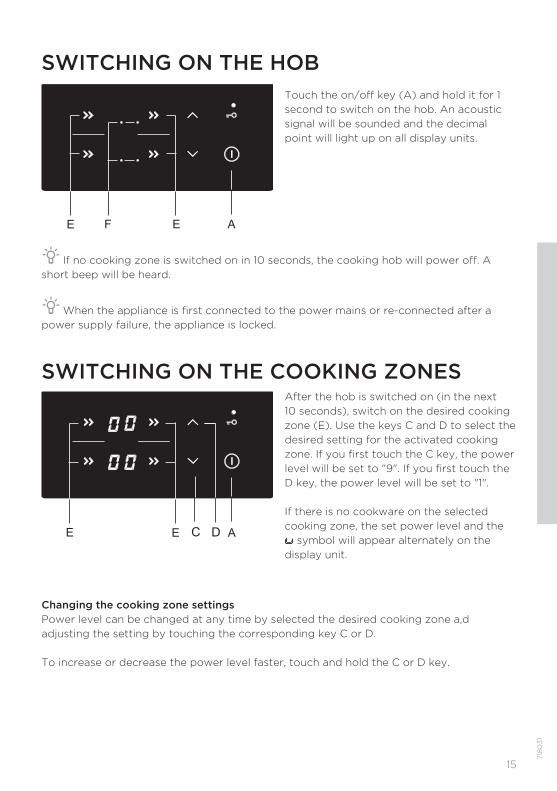
Touch the on/off key (A) and hold it for 1 second to switch on the hob. An acoustic signal will be sounded and the decimal point will light up on all display units.
AEE F
If no cooking zone is switched on in 10 seconds, the cooking hob will power off. A short beep will be heard.
When the appliance is first connected to the power mains or re-connected after a power supply failure, the appliance is locked.
SWITCHING ON THE HOB
Changing the cooking zone settingsPower level can be changed at any time by selected the desired cooking zone a,d adjusting the setting by touching the corresponding key C or D.
To increase or decrease the power level faster, touch and hold the C or D key.
After the hob is switched on (in the next 10 seconds), switch on the desired cooking zone (E). Use the keys C and D to select the desired setting for the activated cooking zone. If you first touch the C key, the power level will be set to "9". If you first touch the D key, the power level will be set to "1".
If there is no cookware on the selected cooking zone, the set power level and the
symbol will appear alternately on the display unit.
AEE DC
SWITCHING ON THE COOKING ZONES

16
7180
31
POWER ZONE WITH THE POWER BOOST OPTIONSelect any cooking zone. Touch the (C) key. A short acoustic signal will be emitted and "9" will appear on the display unit. Touch the D key and P will appear on the display unit. The cooking zone will operate at maximum power for 10 minutes; then, an acoustic signal will be emitted and the power level will switch to 9.
A BEG CC D
Deactivating the power boost- Power can be decreased to desired level by pressing the (C) key.
The cooking zone with the power boost function activated is highly powerful.
17
718
03
1
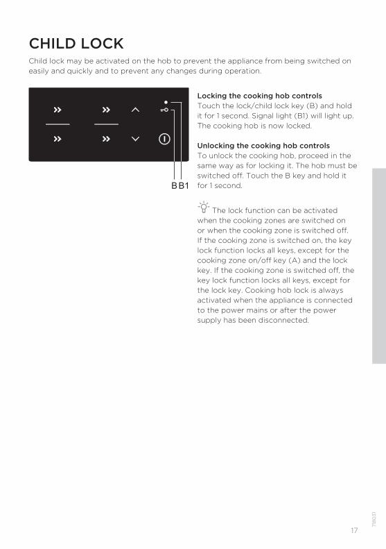
Locking the cooking hob controlsTouch the lock/child lock key (B) and hold it for 1 second. Signal light (B1) will light up. The cooking hob is now locked.
Unlocking the cooking hob controlsTo unlock the cooking hob, proceed in the same way as for locking it. The hob must be switched off. Touch the B key and hold it for 1 second.
The lock function can be activated when the cooking zones are switched on or when the cooking zone is switched off. If the cooking zone is switched on, the key lock function locks all keys, except for the cooking zone on/off key (A) and the lock key. If the cooking zone is switched off, the key lock function locks all keys, except for the lock key. Cooking hob lock is always activated when the appliance is connected to the power mains or after the power supply has been disconnected.
CHILD LOCK Child lock may be activated on the hob to prevent the appliance from being switched on easily and quickly and to prevent any changes during operation.
B B1
18
7180
31
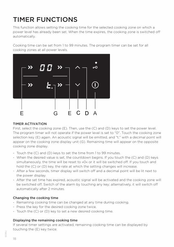
TIMER FUNCTIONSThis function allows setting the cooking time for the selected cooking zone on which a power level has already been set. When the time expires, the cooking zone is switched off automatically.
Cooking time can be set from 1 to 99 minutes. The program timer can be set for all cooking zones at all power levels.
TIMER ACTIVATIONFirst, select the cooking zone (E). Then, use the (C) and (D) keys to set the power level. The program timer will not operate if the power level is set to "0". Touch the cooking zone selection key (E) again. An acoustic signal will be emitted, and "t." with a decimal point will appear on the cooking zone display unit (G). Remaining time will appear on the opposite cooking zone display.
- Touch the (C) and (D) keys to set the time from 1 to 99 minutes.- When the desired value is set, the countdown begins. If you touch the (C) and (D) keys
simultaneously, the time will be reset to »0« or it will be switched off . If you touch and hold the (C) or (D) key, the rate at which the setting changes will increase.
- After a few seconds, timer display will switch off and a decimal point will be lit next to the power display.
- After the set time has expired, acoustic signal will be activated and the cooking zone will be switched off . Switch of the alarm by touching any key; alternatively, it will switch off automatically after 2 minutes.
Changing the cooking time- Remaining cooking time can be changed at any time during cooking.- Press the key for the desired cooking zone twice.- Touch the (C) or (D) key to set a new desired cooking time.
Displaying the remaining cooking timeIf several timer settings are activated, remaining cooking time can be displayed by touching the (E) key twice.
ADEE G C DC
19
718
03
1
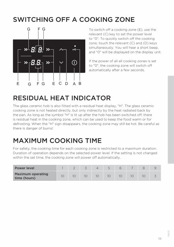
SWITCHING OFF A COOKING ZONETo switch off a cooking zone (E), use the relevant (C) key to set the power level to "0". To quickly switch off the cooking zone, touch the relevant (C) and (D) keys simultaneously. You will hear a short beep, and "0" will be displayed on the display unit.
If the power of all all cooking zones is set to "0", the cooking zone will switch off automatically after a few seconds.
A BDEE FG G
G GF
C
RESIDUAL HEAT INDICATORThe glass ceramic hob is also fitted with a residual heat display, "H". The glass ceramic cooking zone is not heated directly, but only indirectly by the heat radiated back by the pan. As long as the symbol "H" is lit up after the hob has been switched off, there is residual heat in the cooking zone, which can be used to keep the food warm or for defrosting. When the "H" sign disappears, the cooking zone may still be hot. Be careful as there is danger of burns!
MAXIMUM COOKING TIMEFor safety, the cooking time for each cooking zone is restricted to a maximum duration. Duration of operation depends on the selected power level. If the setting is not changed within the set time, the cooking zone will power off automatically.
Power level 1 2 3 4 5 6 7 8 9
Maximum operating time (hours) 10 10 10 10 10 10 10 10 3
20
7180
31
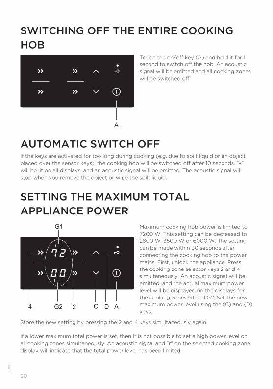
Touch the on/off key (A) and hold it for 1 second to switch off the hob. An acoustic signal will be emitted and all cooking zones will be switched off.
SWITCHING OFF THE ENTIRE COOKING HOB
A
AUTOMATIC SWITCH OFFIf the keys are activated for too long during cooking (e.g. due to spilt liquid or an object placed over the sensor keys), the cooking hob will be switched off after 10 seconds. "–" will be lit on all displays, and an acoustic signal will be emitted. The acoustic signal will stop when you remove the object or wipe the spilt liquid.
Maximum cooking hob power is limited to 7200 W. This setting can be decreased to 2800 W, 3500 W or 6000 W. The setting can be made within 30 seconds after connecting the cooking hob to the power mains. First, unlock the appliance. Press the cooking zone selector keys 2 and 4 simultaneously. An acoustic signal will be emitted, and the actual maximum power level will be displayed on the displays for the cooking zones G1 and G2. Set the new maximum power level using the (C) and (D) keys.
SETTING THE MAXIMUM TOTAL APPLIANCE POWER
A24 DCG2
G1
Store the new setting by pressing the 2 and 4 keys simultaneously again.
If a lower maximum total power is set, then it is not possible to set a high power level on all cooking zones simultaneously. An acoustic signal and "r" on the selected cooking zone display will indicate that the total power level has been limited.
21
718
03
1
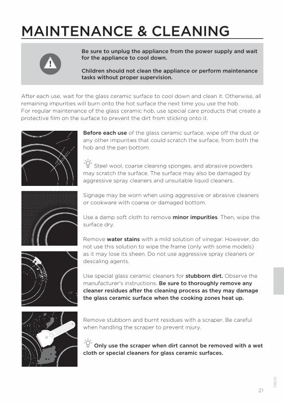
Before each use of the glass ceramic surface, wipe off the dust or any other impurities that could scratch the surface, from both the hob and the pan bottom.
Steel wool, coarse cleaning sponges, and abrasive powders may scratch the surface. The surface may also be damaged by aggressive spray cleaners and unsuitable liquid cleaners.
Signage may be worn when using aggressive or abrasive cleaners or cookware with coarse or damaged bottom.
Use a damp soft cloth to remove minor impurities. Then, wipe the surface dry.
Remove water stains with a mild solution of vinegar. However, do not use this solution to wipe the frame (only with some models) as it may lose its sheen. Do not use aggressive spray cleaners or descaling agents.
Use special glass ceramic cleaners for stubborn dirt. Observe the manufacturer's instructions. Be sure to thoroughly remove any cleaner residues after the cleaning process as they may damage the glass ceramic surface when the cooking zones heat up.
Remove stubborn and burnt residues with a scraper. Be careful when handling the scraper to prevent injury.
Only use the scraper when dirt cannot be removed with a wet cloth or special cleaners for glass ceramic surfaces.
After each use, wait for the glass ceramic surface to cool down and clean it. Otherwise, all remaining impurities will burn onto the hot surface the next time you use the hob.For regular maintenance of the glass ceramic hob, use special care products that create a protective film on the surface to prevent the dirt from sticking onto it.
MAINTENANCE & CLEANINGBe sure to unplug the appliance from the power supply and wait for the appliance to cool down.
Children should not clean the appliance or perform maintenance tasks without proper supervision.

22
7180
31
Hold the scraper at the correct angle (45° to 60°). Gently press the scraper against the glass and slide it over the signage to remove the dirt. Make sure the plastic handle of the scraper (in some models) does not come into contact with a hot cooking zone.
Do not press the scraper perpendicularly against the glass and do not scratch the hob surface with its tip or blade.
Immediately remove any sugar or sugar-laden food from the glass ceramic hob using a scraper, even if the hob is still hot, as sugar may permanently damage the glass ceramic surface.
Any changes to the sheen of the graphic design elements or discolouration should not be deemed as damage to the appliance, but rather a result of normal use of the cooking hob. Such discolouration is most commonly a result of food residues burnt onto the surface, or it may be caused by some cookware materials (such as aluminium or copper). Such discolouration is very difficult to remove entirely.
Note: Discolouration and similar flaws only affect the appearance of the hob and do not directly affect its function. Removing such flaws shall not be covered by the warranty.
23
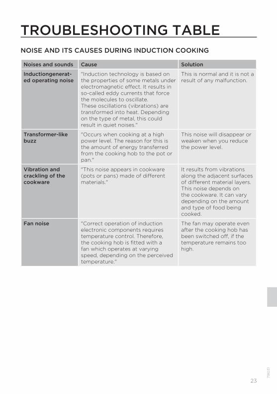
TROUBLESHOOTING TABLENOISE AND ITS CAUSES DURING INDUCTION COOKING
Noises and sounds Cause Solution
Inductiongenerat-ed operating noise
"Induction technology is based on the properties of some metals under electromagnetic effect. It results in so-called eddy currents that force the molecules to oscillate.These oscillations (vibrations) are transformed into heat. Depending on the type of metal, this could result in quiet noises."
This is normal and it is not a result of any malfunction.
Transformer-like buzz
"Occurs when cooking at a high power level. The reason for this is the amount of energy transferred from the cooking hob to the pot or pan."
This noise will disappear or weaken when you reduce the power level.
Vibration and crackling of the cookware
"This noise appears in cookware(pots or pans) made of differentmaterials."
It results from vibrations along the adjacent surfaces of different material layers.This noise depends on the cookware. It can vary depending on the amount and type of food being cooked.
Fan noise "Correct operation of induction electronic components requires temperature control. Therefore, the cooking hob is fitted with a fan which operates at varying speed, depending on the perceived temperature."
The fan may operate even after the cooking hob has been switched off, if the temperature remains too high.
718
03
1
24
SAFETY FUNCTIONS AND ERROR DISPLAY
The cooking hob is fitted with overheating sensors. These sensors can automatically switch off any cooking zone or the entire hob temporarily.
Error, possible cause, solution• Continuous beep and »–« fl ashing on the display.
- Water spilt over sensor surface, or an object placed over the sensors. Wipe the sensor surface.
• »C« on the display- Cooking zone has overheated. Wait for the cooking zone to cool down.
• »r« on the display- This indicates that the desired power level cannot be set because the limit for
maximum total cooking hob power has been activated.
• »F« on the display- This indicates that there has has been an error during operation.
If an error occurs or if the error indicator "F" does not disappear, disconnect the cooking hob from the power mains for a few minutes (undo the fuse or switch off the main switch); then, reconnect the hob to the power mains and switch on the main switch key.
If the problems persist despite observing the advice above, call an authorized service technician. Repair or any warranty claim resulting from incorrect connection or use of the appliance shall not be covered by the warranty. In this case, the user will cover the cost of repair.
Before the repair, disconnect the appliance from the power mains (by removing the fuse or by removing the plug from the wall outlet).
7180
31
25
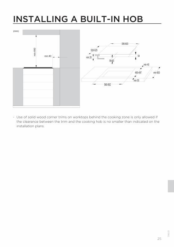
40
595-600
520-525
58-63
54min 20
min 600
min 40
min 50
495-497
560-562
- Use of solid wood corner trims on worktops behind the cooking zone is only allowed if the clearance between the trim and the cooking hob is no smaller than indicated on the installation plans.
INSTALLING A BUILT-IN HOB
718
03
1
26
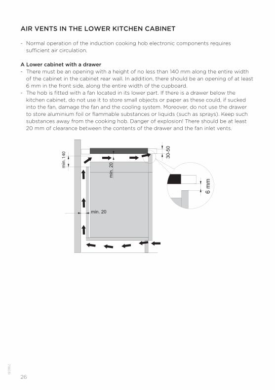
AIR VENTS IN THE LOWER KITCHEN CABINET
- Normal operation of the induction cooking hob electronic components requires suffi cient air circulation.
A Lower cabinet with a drawer- There must be an opening with a height of no less than 140 mm along the entire width
of the cabinet in the cabinet rear wall. In addition, there should be an opening of at least 6 mm in the front side, along the entire width of the cupboard.
- The hob is fi tted with a fan located in its lower part. If there is a drawer below the kitchen cabinet, do not use it to store small objects or paper as these could, if sucked into the fan, damage the fan and the cooling system. Moreover, do not use the drawer to store aluminium foil or fl ammable substances or liquids (such as sprays). Keep such substances away from the cooking hob. Danger of explosion! There should be at least 20 mm of clearance between the contents of the drawer and the fan inlet vents.
7180
31
27
min. 20
40-5
0
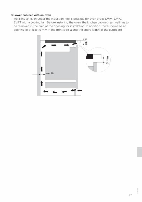
B Lower cabinet with an oven- Installing an oven under the induction hob is possible for oven types EVP4, EVP2,
EVP3 with a cooling fan. Before installing the oven, the kitchen cabinet rear wall has to be removed in the area of the opening for installation. In addition, there should be an opening of at least 6 mm in the front side, along the entire width of the cupboard.
718
03
1
28
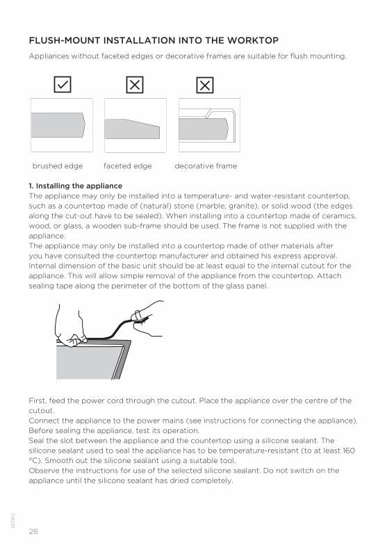
FLUSH-MOUNT INSTALLATION INTO THE WORKTOP
Appliances without faceted edges or decorative frames are suitable for flush mounting.
brushed edge faceted edge decorative frame
1. Installing the applianceThe appliance may only be installed into a temperature- and water-resistant countertop, such as a countertop made of (natural) stone (marble, granite), or solid wood (the edges along the cut-out have to be sealed). When installing into a countertop made of ceramics, wood, or glass, a wooden sub-frame should be used. The frame is not supplied with the appliance.The appliance may only be installed into a countertop made of other materials after you have consulted the countertop manufacturer and obtained his express approval. Internal dimension of the basic unit should be at least equal to the internal cutout for the appliance. This will allow simple removal of the appliance from the countertop. Attach sealing tape along the perimeter of the bottom of the glass panel.
First, feed the power cord through the cutout. Place the appliance over the centre of the cutout.Connect the appliance to the power mains (see instructions for connecting the appliance). Before sealing the appliance, test its operation.Seal the slot between the appliance and the countertop using a silicone sealant. The silicone sealant used to seal the appliance has to be temperature-resistant (to at least 160 °C). Smooth out the silicone sealant using a suitable tool.Observe the instructions for use of the selected silicone sealant. Do not switch on the appliance until the silicone sealant has dried completely.
7180
31
29
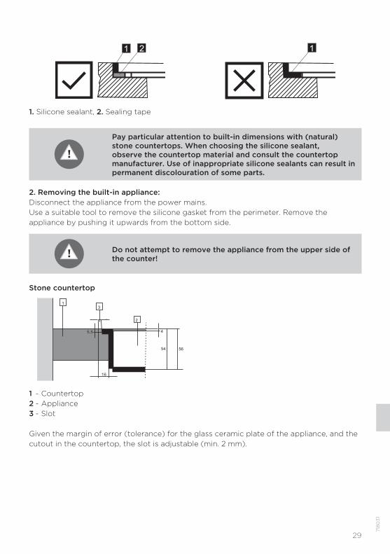
1 2
1
1. Silicone sealant, 2. Sealing tape
Pay particular attention to built-in dimensions with (natural) stone countertops. When choosing the silicone sealant, observe the countertop material and consult the countertop manufacturer. Use of inappropriate silicone sealants can result in permanent discolouration of some parts.
2. Removing the built-in appliance:Disconnect the appliance from the power mains.Use a suitable tool to remove the silicone gasket from the perimeter. Remove the appliance by pushing it upwards from the bottom side.
Do not attempt to remove the appliance from the upper side of the counter!
Stone countertop
13
2
4
16
5,5
5654
1 - Countertop2 - Appliance3 - Slot
Given the margin of error (tolerance) for the glass ceramic plate of the appliance, and the cutout in the countertop, the slot is adjustable (min. 2 mm).
718
03
1

30
Ceramic, wooden, or glass countertop
1 - Countertop2 - Appliance3 - Slot4 - Wooden frame, thickness 16 mm.
7180
31
Given the margin of error (tolerance) for the glass ceramic plate of the appliance, and the cut-out in the countertop, the slot is adjustable (min. 2mm). Install the wooden frame 5.5mm below the upper edge of the countertop (see figure).
Observe the radii of glass edges (R10, R2) when making the cut-out.
GLASS CUT-OUT
R2
R2 R2
R2 R5
R5 R5
R5
R2
R10 R10
R2 R5
R12 R12
R5
31
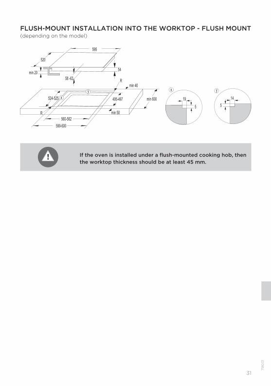
FLUSH-MOUNT INSTALLATION INTO THE WORKTOP - FLUSH MOUNT (depending on the model)
718
03
1
595
520
58 -63
min 50
54
599-600
495-497
min 40
min 600 524-525
560-562
xy
19
5
x
14
5
y
R
R
min 20
If the oven is installed under a flush-mounted cooking hob, then the worktop thickness should be at least 45 mm.
32
- The worktop has to be completely level.- Protect the cut out surfaces.
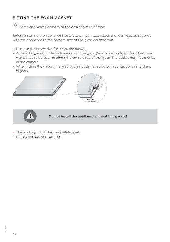
FITTING THE FOAM GASKET
Some appliances come with the gasket already fitted!
Before installing the appliance into a kitchen worktop, attach the foam gasket supplied with the appliance to the bottom side of the glass ceramic hob.
- Remove the protective fi lm from the gasket.- Attach the gasket to the bottom side of the glass (2–3 mm away from the edge). The
gasket has to be applied along the entire edge of the glass. The gasket may not overlap in the corners.
- When fi tting the gasket, make sure it is not damaged by or in contact with any sharp objects.
Do not install the appliance without this gasket!
7180
31
CONNECTING THE COOKING HOB TO THE POWER MAINS- Power mains protection must conform to the relevant regulations.- Before connecting the appliance, make sure the voltage indicated on the rating plate
conforms to the voltage in your power mains.- There should be a switching device in the electrical installation that can disconnect
all poles of the appliance form the power mains, with a minimum clearance of 3 mm between the contacts when open. Suitable devices include fuses, protective switches etc.
- The connection should be adjusted to the current and fuses.- After installation, the parts carrying electrical current and insulated parts shall be
protected against contact.
The appliance may only be connected by an authorized expert. False connection can destroy parts of the appliance. In such case, there is no right to warranty.Disconnect the appliance from the power mains before any repair or maintenance operation.
33
718
03
1
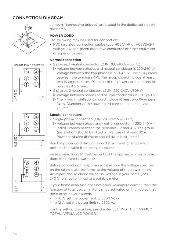
CONNECTION DIAGRAM:
Jumpers (connecting bridges) are placed in the dedicated slot on the clamp.
POWER CORDThe following may be used for connection:• PVC insulated connection cables type H05 VV-F or H05V2V2-F
with yellow-and-green protective conductor, or other equivalent or superior cables.
Normal connection• 2 phases, 1 neutral conductor (2 1N, 380-415 V~/50 Hz):
Voltage between phases and neutral conductor is 220-240 V~. Voltage between the two phases is 380-415 V~. Install a jumper between the terminals 4–5. The group should include at least two 16-ampere fuses. Diameter of the power cord core should be at least 2.5 mm2.
• 2 phases, 2 neutral conductors (2 2N, 220-240V~/50Hz): Voltage between phases and neutral conductors is 220-240 V~. The group (installation) should include at least two 16-ampere fuses. Diameter of the power cord core should be at least 2.5 mm2.
Special connection:• Single-phase connection (1 1N, 220-240 V~/50 Hz):
Voltage between phase and neutral conductor is 220-240 V~. Install jumpers between the terminals 1–2 and 4–5. The group (installation) should be fi tted with a fuse of at least 32 A. Power cord core diameter should be at least 4 mm2.
Run the power cord through a cord strain relief (clamp) which protects the cable from being pulled out.
False connection can destroy parts of the appliance. In such case, there is no right to warranty.
Before connecting the appliance, make sure the voltage specified on the rating plate conforms to the voltage of the power mains.An expert should check the actual voltage in your home (220-240 V relative to N), using a suitable meter!
If your home main fuse does not allow 32-ampere current, then the function of total power limiter can be activated on the hob so that the current never exceeds:- 1 x 16 A, set the power limit to 3500 W, or- 1 x 12 A, set the power limit to 2800 W.
For the setting procedure, see chapter SETTING THE MAXIMUM TOTAL APPLIANCE POWER.
2N 380-415V
2 2N 220 240V
34
7180
31
35
718
03
1
DISPOSAL
Packaging is made of environmentally friendly materials that can be recycled, disposed of, or destroyed without any hazard to the environment. To this end, packaging materials are labelled appropriately.
The symbol on the product or its packaging indicates that the product should not be treated as normal household waste. The product should be taken to an authorized collection centre for waste electric and electronic equipment processing.
Correct disposal of the product will help prevent any negative effects on the environment and health of people which could occur in case of incorrect product removal. For detailed information on removal and processing of the product, please contact the relevant municipal body in charge of waste management, your waste disposal service, or the store where you bought the product.
We reserve the right to any changes and errors in the instructions for use.

BI4 7G en (10-18)