determining a sufficient depth of pile foundation on …
TRANSCRIPT

46 BULLETIN OF THE MARINE GEOLOGYVolume 24 No. 1, June 2009
DETERMINING A SUFFICIENT DEPTH OF PILE FOUNDATION ON THE PERTAMINA GRAVING DOCK DESIGN SORONG
PAPUA
by
Franto Novico 1)
(Manuscript received January 05, 2009)
ABSTRACT
Engineering geological aspect and bearing capacity of pile foundation are significant for safetyof upper structure, especially for substantial constructions such as a docking ship. Moreover, itprovides effectiveness and cost efficiency when applies in rural areas of Indonesia. This is due tolack of docking ship appropriately built at rural areas particularly in eastern areas of Indonesia.Karim island of Papua even though is a small island yet is very strategic as Pertamina place itstransitory function on that island connecting its oil supply route to Sorong.
Appropriate docking ship construction is required to aim the effective and efficient portmanagement. Choosing the most suitable structure for a docking is also the key. Graving dockstructure has been chosen by Pertamina as the most appropriate type of structure for the dockingship in Karim Island. The structure of graving dock planned to be built in Karim island Papua, isprojected to be able to serve the maximum 7500 DWT ship capacity, with approximatelydimension is 125 x 25 x 8 meters. Therefore, to support the plan, type and design of the bestfoundation is the key.
There are two methods could be done in determining the type and bearing capacity foundation.Field and laboratory test applied ASTM, field observation result by applying Meyerhoff theoryand laboratorial analysis derived from Tarzaghi theory.
Those observation and analysis has confirmed that the soil layer at the graving dock designconsists of three layers, those are; cover layer, silt-clay layer and clay rock unit. Therefore, themost suitable foundation to be constructed in that area is a pile massive foundation, with depth ofpile foundation approximately -20 m below the land surface, and the ultimate point load pilemassive for 30x30 cm – 75x75 cm dimension approximately 79.76 – 406.25 ton, and frictionalresistance value approximately 24.59 – 61.48 ton.
Keyword : Pile Pondation, bearing capacity, Graving dock
1. Marine Geological Institute, Jl. Dr. Junjunan No. 236 Bandung
47BULLETIN OF THE MARINE GEOLOGYVolume 24 No. 1, June 2009
SARI
Aspek geologi teknik dan besarnya nilai kapasitas suatu pondasi tiang pancang merupakansuatu hal yang sangat penting demi keamanan pembangunan struktur bagian atas, khususnyauntuk bangunan yang besar dan tinggi. Pembuatan dok kapal menjadi tuntutan yang tak bisadielakkan demi terlengkapinya manajemen pelabuhan yang efektif dan efisiensi pada daerah yangterpencil. Bangunan graving dock kapal yang direncanakan pada Pulau Karim Papua,diproyeksikan untuk dapat melayani kapal dengan kapasitas maksimal 7500 DWT, dengandimensi berkisar 125 x 25 x 8 meter. Jenis dan perencanaan pondasi yang tepat sangat pentingguna menunjang keamanan bangunan graving dock itu sendiri.
Metoda yang digunakan untuk mengetahui jenis pondasi dan daya dukung pondasi didapatdari hasil uji lapangan dan laboratorium. Pengujian lapangan dan laboratorium berdasarkanASTM, analisis data lapangan mempergunakan metoda Mayerhoff sedangkan analisis datalaboratorium mempergunakan metoda Terzaghi.
Lapisan tanah pada rencana graving dock terdiri dari tiga bagian yaitu; lapisan penutup,lempung lanauan dan satuan batuan lempung. Untuk itu jenis pondasi yang dipilih adalahpondasi tiang pancang massif. Kedalaman pemancangan pondasi berkisar -20m dari muka tanah.Hasil analisis menunjukkan kuat tekan tiang pancang massif untuk diameter 30x30 cm hingga75x75 cm berkisar 79.76 – 406.25 ton, sedangkan untuk nilai tarik berkisar dari 24.59 hingga61.48 ton.
Kata Kunci : Tiang pancang, nilai kapasitas, Graving dock
INTRODUCTION The growth of transportation activities
in eastern area of Indonesia, in particularSorong, must be supported bydevelopment of docking ship services.Pertamina is recorded as the most activeuser of docking ship service in Sorong dueto its business strategy to supply oil toSorong. It is unavoidable that Pertamina isrequired to construct a proper and strongdocking ship with capacity of which isadjusted with the needs for supplying oilto Sorong.
According to Pertamina’s plan, thegraving dock ship is estimated to be ableto serve maximum 7500 DWT capacityship, with dimension approximately 125 x25 x 8 meter. It is categorized as mediumsize of dock ship. For success of thegraving dock ship construction, careful
consideration in choosing the bestfoundation of the dock ship is crucial.
GEOLOGICAL CONDITION
Morphology and stratigraphy for Graving Dock Design
Morphology The topography of the Pertamina’s
graving dock design in Karim Island hasan elevation degree of about +2.5 m fromLWS (figure 1).
StratigraphyBased on geological regional map,
specially as appeared in the Soronggeological map sheet and fieldobservation, Karim Island stratigraphyconsists of alluvial river suspended andlittoral deposits. The area of which hasbeen dominated by coral rock of

48 BULLETIN OF THE MARINE GEOLOGYVolume 24 No. 1, June 2009
quartenary age with depth about 30meter, which comprises of sand, gravel,mud, organic material and peat moss.
From the drilling result in 5 (five)locations which were executed on thegraving dock design area (BM-I, BM-II,BM-III, BM-IV and BM-V), stratigraphy ofKarim Island according to age (from theoldest are): • Claystone (Fm. Klasaman), gray to
dark green, low to high plasticity, softto compact density, consists ofsandstone quartz, clay to clay, peatmoss and lignite, plants residue, thishas been formed since the age of endMiosen – Plistosen.
• Alluvial, brown to white grayishconsist of mud, sand, pebble, gravel, (fragment of coral reef) dirty yellowwith diameter 1-8 cm, and the losscharacteristic, produced from littorals
suspended, this has been formed sincethe age of Resen
Geology StructureGeological structure in Karim Island,
especially for graving dock area, is notdeveloped due to the thickness ofsuspended alluvium. Lithic surfacecharacter of the geological structure couldonly be found through core drilling BM-IIIand core drilling BM-V with the slope(dip) 28º - 30º, with the direction arenortheast – southwest.
Geological FoundationIt is obvious that previous land
extension on the area had been done. It isindicated by the different material fillingon the upper layer of the extension areaand 5.00 meter depth of excavation on thedesigned graving dock area containing of
Figure 1. Area of study

49BULLETIN OF THE MARINE GEOLOGYVolume 24 No. 1, June 2009
the clay-sand. However, the core drillingtest suggests that clay-stone is found inthe 20.00 meter depth.
METHOD
GeneralTo get the sufficient depth of pile, the
analysis was started from soilinvestigation. Pile design could beplanned based on laboratory analysis orfield observation (cone penetration test orstandard penetration test). It is known,foundation is the most vital element in thestructure as it supports and holds out thepressure from upper structure. In otherwords, it has a connecting functionbetween the upper structure pressure andbase soil or rock layer resistance.Specifically, a bearing capacity of pile isdivided into three types of friction, an endbearing piles (figure 2), a friction piles(figure 3) and a combination both of them.
A different soil can give a differentresult of resistance respectively. In the
next section can be found more detailabout bearing capacity of foundation.
Bearing Capacity of FoundationBearing capacity of foundation is a
foundation capability to support an upperstructure, focusing on vertical, lateral, anduplift load force. Bearing capacity offoundation depends on two main factors;material of the foundation and type ofsoil. Soil sample must be collected to getinformation about the properties of thesoil and correlation with the pile design.To determine bearing capacity, twomethods were used: Meyerhof andTerzaghi. Meyerhof used data on fieldobservation and Terzaghi on laboratoryanalysis.
Mayerhof Method:
Qu= 40 Nb.Ap + 0.2 N AsQfs= 0.2 N AsQp= 40 Nb. Ab

50 BULLETIN OF THE MARINE GEOLOGYVolume 24 No. 1, June 2009
Where:Qu = Point bearing capacity (ton)Qfs = Frictional resistance (ton)Qp = Top pole resistance (ton)4Nb = Average value N SPT at 4d under
pile and 8d above pileAb = Average area of cross section of
the pile (m2)As = Cover wide of pile (m2)N = Average value N SPT deep length
pile SF = Safety factor (use 2.5)
Permitted of bearing capacity pile is
Q (-)= Qu/SFQ (+)= Qfs/SF
Bearing capacity of foundation basedon laboratorial test
Calculation of End Resistance(Terzaghi)
Qb = Ab x (1.3 x c x Nc + pb’ x Nq + 0.4 xγ x b x Nγ)
Where:Qb = Resistance of point Ultimate (ton)Ab = Average area of cross section of
the pile (m2)c = Cohesion of the soil supporting
the pile tip (ton/m2)Nc, Nγ, Nq=The bearing capacity factors,
Costet J & Sanglerat (1983) γ = Weight of soil volume (ton/m3)b = Pile dimension
Calculation Friction ResistanceUltimate
Friction Resistance Ultimate fromfriction component
Qs1 = Kd x po’ x tgδ x As
Where:Qs1 = Friction resistance ultimate from
friction componentKd = Material pile coefficient, Brom
(1965)Po’ = Average Pressure overburden
effective in length of pile (ton/m2)Tg δ= Friction angle drainage between
wall pile and soil.As = Cover wide pile (m2)
Friction Resistance Ultimate fromcohesion component
Qs2 = Ad x cu x As
Where:Qs2 = Friction resistance ultimate from
cohesion componentAd = Adhesion factor for pile
(McClelland, 1974) As = Cover wide of pile (m2)
Total Friction Resistance:
Qs = Qs1 + Qs2
Pile Capacity:
Qall(-) = (1/FK) x (Qs + Qb - Wp)Qall(+) = (1/FK) x (Kd x po’ x tgδ x
As )+( Ad x cu x As)
Pile weight: Wp = L x γbtn x As
Where:L = pile length (m)γbtn = weight volume of concrete 2.4 (ton/
m3)

51BULLETIN OF THE MARINE GEOLOGYVolume 24 No. 1, June 2009
RESULT
Geological FoundationDrilling and Standard Penetration Test
(SPT) had been executed at 5 points in thedock draft location. Those are BM-I, BM-II, BM-III, BM-IV, and BM-V. Each drillingdepth was up to 40 meter. Undisturbedsample had also been taken from thedrilling test. This was used to determine
engineering properties through alaboratorial test. Whilst, the disturbedsample was taken during the drillingprocess. Disturbed sample coulddistinguish the lithology type pursuant toUnited Soil Classification System thatshown in Boring log form. From the logbore result, it is known that geologicalfoundation in graving dock design
Table 1. Test Soil Mechanics Result

52 BULLETIN OF THE MARINE GEOLOGYVolume 24 No. 1, June 2009
consists of fill material, clay-sand unit,and clay rock unit.
Filling materialFilling material is white-brown-gray
color, consists of sand material, smallgravel, mud, big gravel, φ 1 – 8 cm, nonplastic, apart compaction – middle, withthe thickness of 4,00 – 8,45 m. From theresult of the boring log, it is also revealedthat the depth of filling material turns outto be thicker towards the sea. Based onobservation, ground water level in thisarea is about 50 cm from ground surface.Since the filling material has loose tocompact characteristic, careful attentionfrom the contractor during excavationprocess is highly required.
Silt-Clay UnitSilt-clay is in bright gray to brown
color, low to middle plasticity, soft to veryrigid consistency, middle level ofcompact. The thickness is about 3,90 – 13m and the SPT range is 4 – 25.
Clay stone unitClay stone is in gray to green color,
middle to high plasticity, middle toMoveto discussion section. solid compact, andvery rigid. The thickness is about 23 –29,70 m and the SPT range is >20.
Laboratory analysis and StandardPenetration Test
In order to get the information of thesoil index properties and soil engineeringproperties, some tests were done such as,unit weight, grain size, water content,atterberg limit, specific gravity. Besides, toobtain engineering properties the UUtriaxial test and consolidation test shouldbe done.
Soil test was carried out onundisturbed and disturbed soil. See Table
1 for result. The test result of the sample inthe laboratory shows soil engineeringproperties. This is to gauge the soilstrength parameters from cohesion value (c ) and angle of internal friction. Thiscould be used as a basis to draw thefoundation design. The following is thetest result of the calculation of pile bearingcapacity which has been prepared basedon soil parameters that are held in thelaboratory by applying some piledimension alternative and pile depth inevery drilling location (BM). In addition,the pile dimension has been created as30x30 cm, 40x40 cm, 50x50 cm, 60x60 cm,and 75x75 cm. Standard Penetration Testwas implemented during borings. Soil testby SPT was supposed to recognize soilstrength and bearing capacity of soil.Standard Penetration Test should be donetogether with drilling process and shallcomply with ASTM D1586.
Foundation Analysis Foundation analysis’s recommen-
dation, is prepared based on theobservation data and field test asappeared in the bore hole log descriptionand (n-SPT) also laboratory test (Triaxialtest). The observation and field testindicates that the hard soil layer (n>30) islocated in the depth of -20 m below soilsurface. Thus, the capacity calculation willbe applied at -20m depth. However, abearing capacity of pile has been executedbased on two data:
Observation data (N-SPT)Parameters that is used is depth, N-
SPT (strike number), and pile dimension.
Laboratory test data (Triaxial Test)Parameters that is applied are cohesion
( c ), angle of internal friction ( ϕ ), soil
53BULLETIN OF THE MARINE GEOLOGYVolume 24 No. 1, June 2009
weight volume, depth (H) and piledimension.
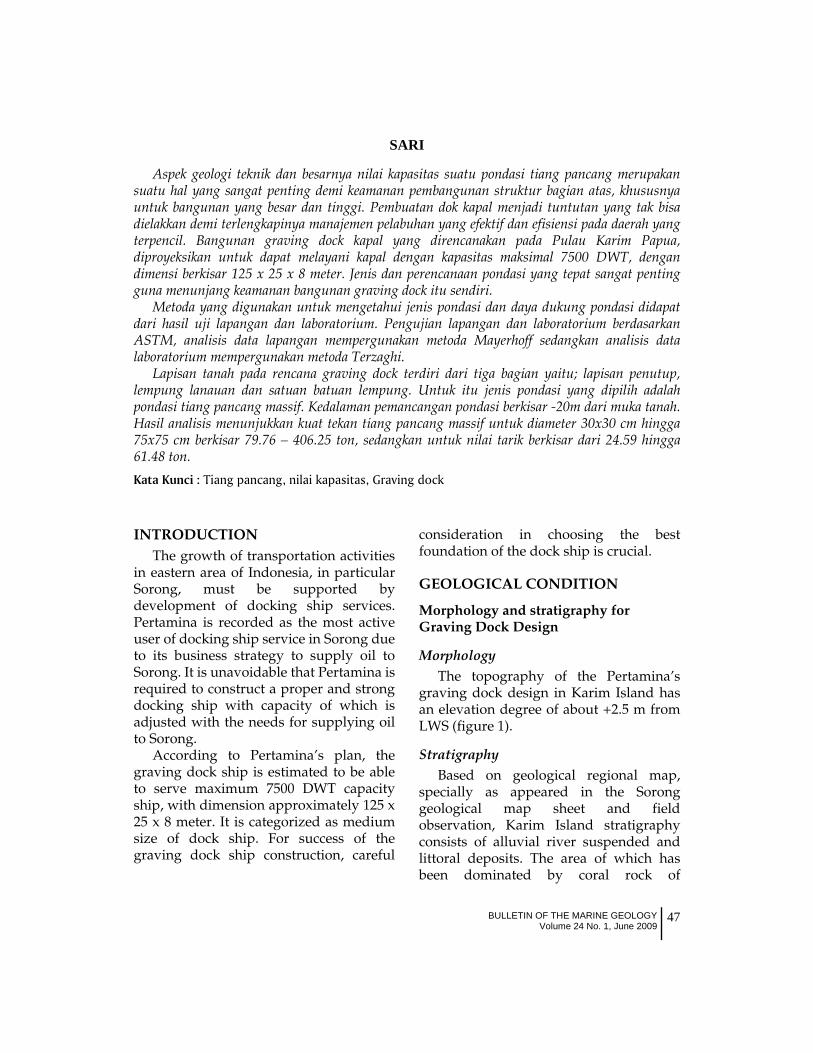
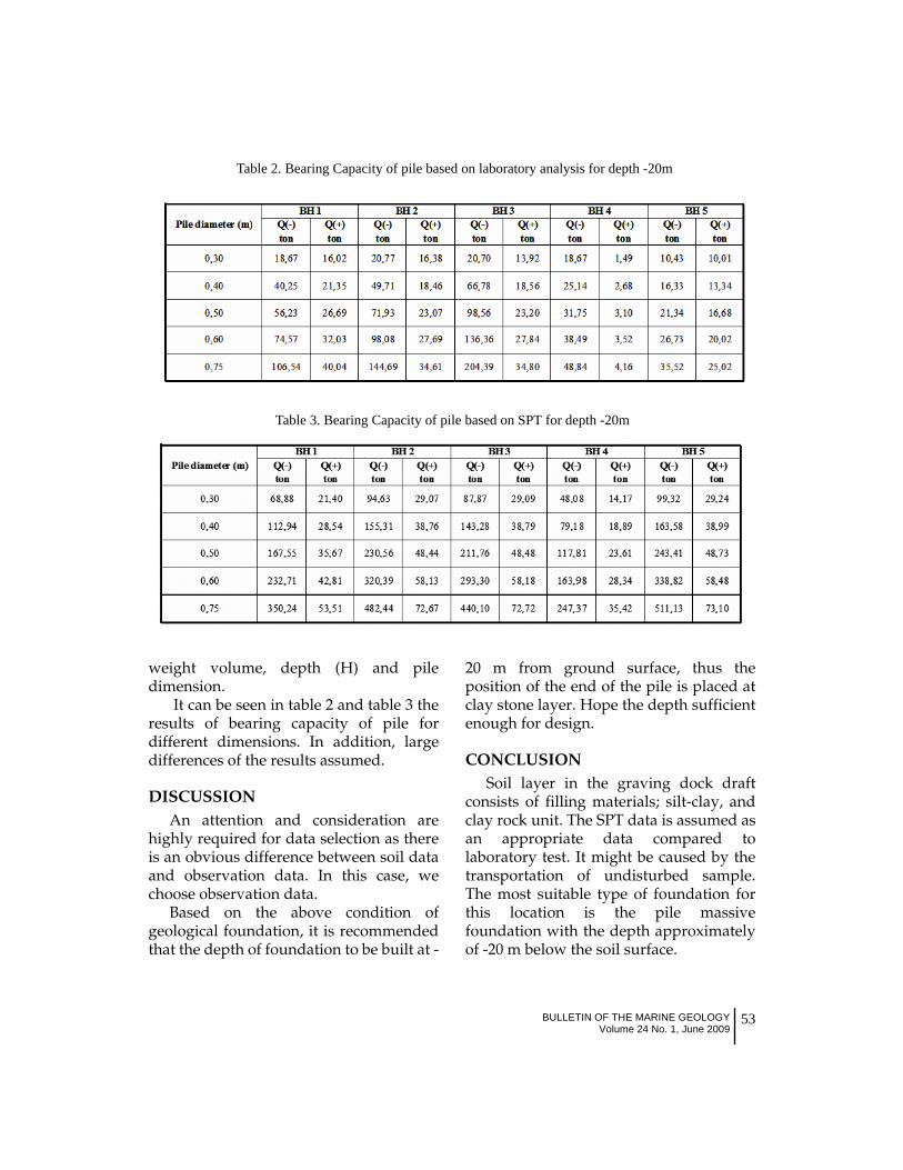
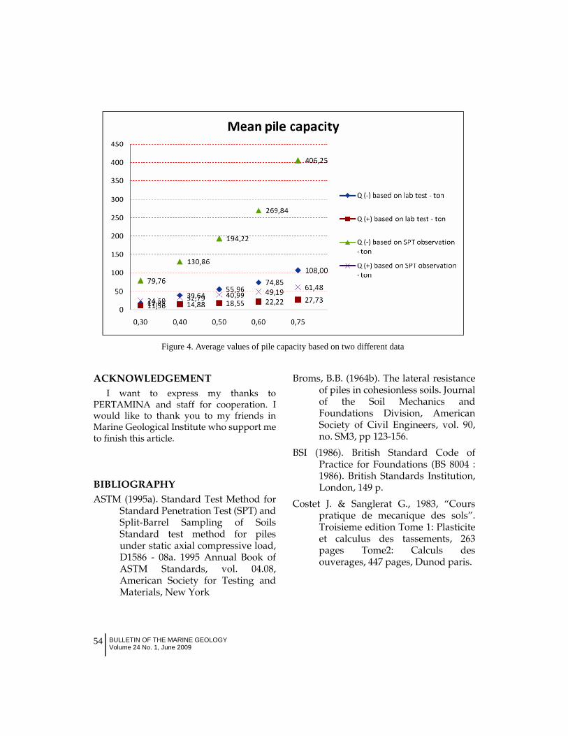
It can be seen in table 2 and table 3 theresults of bearing capacity of pile fordifferent dimensions. In addition, largedifferences of the results assumed.
DISCUSSIONAn attention and consideration are
highly required for data selection as thereis an obvious difference between soil dataand observation data. In this case, wechoose observation data.
Based on the above condition ofgeological foundation, it is recommendedthat the depth of foundation to be built at -
20 m from ground surface, thus theposition of the end of the pile is placed atclay stone layer. Hope the depth sufficientenough for design.
CONCLUSIONSoil layer in the graving dock draft
consists of filling materials; silt-clay, andclay rock unit. The SPT data is assumed asan appropriate data compared tolaboratory test. It might be caused by thetransportation of undisturbed sample.The most suitable type of foundation forthis location is the pile massivefoundation with the depth approximatelyof -20 m below the soil surface.
Table 2. Bearing Capacity of pile based on laboratory analysis for depth -20m
Table 3. Bearing Capacity of pile based on SPT for depth -20m
54 BULLETIN OF THE MARINE GEOLOGYVolume 24 No. 1, June 2009
ACKNOWLEDGEMENTI want to express my thanks to
PERTAMINA and staff for cooperation. Iwould like to thank you to my friends inMarine Geological Institute who support meto finish this article.
BIBLIOGRAPHYASTM (1995a). Standard Test Method for
Standard Penetration Test (SPT) andSplit-Barrel Sampling of SoilsStandard test method for pilesunder static axial compressive load,D1586 - 08a. 1995 Annual Book ofASTM Standards, vol. 04.08,American Society for Testing andMaterials, New York
Broms, B.B. (1964b). The lateral resistanceof piles in cohesionless soils. Journalof the Soil Mechanics andFoundations Division, AmericanSociety of Civil Engineers, vol. 90,no. SM3, pp 123-156.
BSI (1986). British Standard Code ofPractice for Foundations (BS 8004 :1986). British Standards Institution,London, 149 p.
Costet J. & Sanglerat G., 1983, “Courspratique de mecanique des sols”.Troisieme edition Tome 1: Plasticiteet calculus des tassements, 263pages Tome2: Calculs desouverages, 447 pages, Dunod paris.
Figure 4. Average values of pile capacity based on two different data