objectarx.net developer'sguide · overview introduction the autocad® map 3d 2008 .net api...
TRANSCRIPT

AutoCAD® Map 3D 2009
ObjectARX .NETDeveloper's Guide
April 2008

© 2008 Autodesk, Inc. All Rights Reserved. Except as otherwise permitted by Autodesk, Inc., this publication, or parts thereof, may not bereproduced in any form, by any method, for any purpose. Certain materials included in this publication are reprinted with the permission of the copyright holder. TrademarksThe following are registered trademarks or trademarks of Autodesk, Inc., in the USA and other countries: 3DEC (design/logo), 3December,3December.com, 3ds Max, ActiveShapes, Actrix, ADI, Alias, Alias (swirl design/logo), AliasStudio, Alias|Wavefront (design/logo), ATC, AUGI,AutoCAD, AutoCAD Learning Assistance, AutoCAD LT, AutoCAD Simulator, AutoCAD SQL Extension, AutoCAD SQL Interface, Autodesk, AutodeskEnvision, Autodesk Insight, Autodesk Intent, Autodesk Inventor, Autodesk Map, Autodesk MapGuide, Autodesk Streamline, AutoLISP, AutoSnap,AutoSketch, AutoTrack, Backdraft, Built with ObjectARX (logo), Burn, Buzzsaw, CAiCE, Can You Imagine, Character Studio, Cinestream, Civil3D, Cleaner, Cleaner Central, ClearScale, Colour Warper, Combustion, Communication Specification, Constructware, Content Explorer,Create>what's>Next> (design/logo), Dancing Baby (image), DesignCenter, Design Doctor, Designer's Toolkit, DesignKids, DesignProf, DesignServer,DesignStudio, Design|Studio (design/logo), Design Your World, Design Your World (design/logo), DWF, DWG, DWG (logo), DWG TrueConvert,DWG TrueView, DXF, EditDV, Education by Design, Exposure, Extending the Design Team, FBX, Filmbox, FMDesktop, Freewheel, GDX Driver,Gmax, Heads-up Design, Heidi, HOOPS, HumanIK, i-drop, iMOUT, Incinerator, IntroDV, Inventor, Inventor LT, Kaydara, Kaydara (design/logo),LocationLogic, Lustre, Maya, Mechanical Desktop, MotionBuilder, Mudbox, NavisWorks, ObjectARX, ObjectDBX, Open Reality, Opticore,Opticore Opus, PolarSnap, PortfolioWall, Powered with Autodesk Technology, Productstream, ProjectPoint, ProMaterials, Reactor, RealDWG,Real-time Roto, Recognize, Render Queue, Reveal, Revit, Showcase, ShowMotion, SketchBook, SteeringWheels, StudioTools, Topobase, Toxik,ViewCube, Visual, Visual Bridge, Visual Construction, Visual Drainage, Visual Hydro, Visual Landscape, Visual Roads, Visual Survey, Visual Syllabus,Visual Toolbox, Visual Tugboat, Visual LISP, Voice Reality, Volo, Wiretap, and WiretapCentral The following are registered trademarks or trademarks of Autodesk Canada Co. in the USA and/or Canada and other countries: Backburner,Discreet, Fire, Flame, Flint, Frost, Inferno, Multi-Master Editing, River, Smoke, Sparks, Stone, and Wire All other brand names, product names or trademarks belong to their respective holders. DisclaimerTHIS PUBLICATION AND THE INFORMATION CONTAINED HEREIN IS MADE AVAILABLE BY AUTODESK, INC. "AS IS." AUTODESK, INC. DISCLAIMSALL WARRANTIES, EITHER EXPRESS OR IMPLIED, INCLUDING BUT NOT LIMITED TO ANY IMPLIED WARRANTIES OF MERCHANTABILITY ORFITNESS FOR A PARTICULAR PURPOSE REGARDING THESE MATERIALS. Published by:Autodesk, Inc.111 Mclnnis ParkwaySan Rafael, CA 94903, USA
Contents
Chapter 1 Overview . . . . . . . . . . . . . . . . . . . . . . . . . . . . . . 1Introduction . . . . . . . . . . . . . . . . . . . . . . . . . . . . . . . . 1Using the API Reference . . . . . . . . . . . . . . . . . . . . . . . . . . 2Setting Up Visual Studio . . . . . . . . . . . . . . . . . . . . . . . . . . 2AutoCAD . . . . . . . . . . . . . . . . . . . . . . . . . . . . . . . . . . 5
Chapter 2 Session and Project . . . . . . . . . . . . . . . . . . . . . . . . . 7Overview . . . . . . . . . . . . . . . . . . . . . . . . . . . . . . . . . . 7Drawing Objects . . . . . . . . . . . . . . . . . . . . . . . . . . . . . . 10
Chapter 3 Object Data . . . . . . . . . . . . . . . . . . . . . . . . . . . . 11Introduction . . . . . . . . . . . . . . . . . . . . . . . . . . . . . . . . 11Creating a Table . . . . . . . . . . . . . . . . . . . . . . . . . . . . . . 12Attaching Object Data . . . . . . . . . . . . . . . . . . . . . . . . . . . 14Getting Object Data . . . . . . . . . . . . . . . . . . . . . . . . . . . . 14Updating and Deleting Records . . . . . . . . . . . . . . . . . . . . . . 16
Chapter 4 Data Connect . . . . . . . . . . . . . . . . . . . . . . . . . . . 19Overview . . . . . . . . . . . . . . . . . . . . . . . . . . . . . . . . . 19Setting Up Visual Studio . . . . . . . . . . . . . . . . . . . . . . . . . 20Creating the Plugin . . . . . . . . . . . . . . . . . . . . . . . . . . . . 21
iii
Chapter 5 Annotation . . . . . . . . . . . . . . . . . . . . . . . . . . . . 25Overview . . . . . . . . . . . . . . . . . . . . . . . . . . . . . . . . . 25Annotation Templates . . . . . . . . . . . . . . . . . . . . . . . . . . . 25Expressions in Annotations . . . . . . . . . . . . . . . . . . . . . . . . 28Inserting Annotations . . . . . . . . . . . . . . . . . . . . . . . . . . . 29Updating and Refreshing Annotations . . . . . . . . . . . . . . . . . . 30Annotation Overrides . . . . . . . . . . . . . . . . . . . . . . . . . . . 30
Chapter 6 Events . . . . . . . . . . . . . . . . . . . . . . . . . . . . . . . 33Overview . . . . . . . . . . . . . . . . . . . . . . . . . . . . . . . . . 33Events in the API Reference . . . . . . . . . . . . . . . . . . . . . . . . 33List of Events . . . . . . . . . . . . . . . . . . . . . . . . . . . . . . . 35
Chapter 7 Drawing Sets . . . . . . . . . . . . . . . . . . . . . . . . . . . 43Overview . . . . . . . . . . . . . . . . . . . . . . . . . . . . . . . . . 43Drive Aliases . . . . . . . . . . . . . . . . . . . . . . . . . . . . . . . . 43Attaching and Detaching Drawings . . . . . . . . . . . . . . . . . . . . 44
Chapter 8 Queries and Save Sets . . . . . . . . . . . . . . . . . . . . . . . 45Overview . . . . . . . . . . . . . . . . . . . . . . . . . . . . . . . . . 45Queries . . . . . . . . . . . . . . . . . . . . . . . . . . . . . . . . . . . 45Query Libraries . . . . . . . . . . . . . . . . . . . . . . . . . . . . . . 48Save Sets . . . . . . . . . . . . . . . . . . . . . . . . . . . . . . . . . . 48
Chapter 9 Classification . . . . . . . . . . . . . . . . . . . . . . . . . . . 49Overview . . . . . . . . . . . . . . . . . . . . . . . . . . . . . . . . . 49Managing Feature Definition Files . . . . . . . . . . . . . . . . . . . . 49Creating Feature Class Definitions . . . . . . . . . . . . . . . . . . . . 50Classifying Objects . . . . . . . . . . . . . . . . . . . . . . . . . . . . 52
Chapter 10 Filters . . . . . . . . . . . . . . . . . . . . . . . . . . . . . . . 53Overview . . . . . . . . . . . . . . . . . . . . . . . . . . . . . . . . . 53Basic Filters . . . . . . . . . . . . . . . . . . . . . . . . . . . . . . . . 53Custom Filters . . . . . . . . . . . . . . . . . . . . . . . . . . . . . . . 54
Chapter 11 Import/Export . . . . . . . . . . . . . . . . . . . . . . . . . . . 55Overview . . . . . . . . . . . . . . . . . . . . . . . . . . . . . . . . . 55Importing . . . . . . . . . . . . . . . . . . . . . . . . . . . . . . . . . 55Exporting . . . . . . . . . . . . . . . . . . . . . . . . . . . . . . . . . 56
Chapter 12 Topology . . . . . . . . . . . . . . . . . . . . . . . . . . . . . . 59
iv | Contents
Overview . . . . . . . . . . . . . . . . . . . . . . . . . . . . . . . . . 59Drawing Cleanup . . . . . . . . . . . . . . . . . . . . . . . . . . . . . 60Creating Topologies . . . . . . . . . . . . . . . . . . . . . . . . . . . . 63Node Topology . . . . . . . . . . . . . . . . . . . . . . . . . . . . . . 63Network Topology . . . . . . . . . . . . . . . . . . . . . . . . . . . . . 64Polygon Topology . . . . . . . . . . . . . . . . . . . . . . . . . . . . . 64
Chapter 13 Display Manager . . . . . . . . . . . . . . . . . . . . . . . . . 65Overview . . . . . . . . . . . . . . . . . . . . . . . . . . . . . . . . . 65Elements . . . . . . . . . . . . . . . . . . . . . . . . . . . . . . . . . . 66Data Source Descriptors . . . . . . . . . . . . . . . . . . . . . . . . . . 67Style . . . . . . . . . . . . . . . . . . . . . . . . . . . . . . . . . . . . 70
Chapter 14 MapBook . . . . . . . . . . . . . . . . . . . . . . . . . . . . . 73Overview . . . . . . . . . . . . . . . . . . . . . . . . . . . . . . . . . 73MapBook Templates . . . . . . . . . . . . . . . . . . . . . . . . . . . . 73Creating a Map Book . . . . . . . . . . . . . . . . . . . . . . . . . . . 74
Index . . . . . . . . . . . . . . . . . . . . . . . . . . . . . . . . 75
Contents | v

vi
Overview
IntroductionThe AutoCAD® Map 3D 2008 .NET API provides access to AutoCAD Map 3Dfunctionality so you can modify and extend it for your own purposes. The APIcan be used by any .NET language.
The snippets in this guide are mainly in VB.NET, but most samples are availablein VB.NET, C#, and C++.
Some of the short snippets in this guide write to the AutoCAD Map 3D console.Ensure that the console is visible. Press CTRL+9 to display the or hide console.
Namespaces
The Autodesk.Gis.Map namespace contains the .NET classes for AutoCAD Map3D. Some of the general-purpose classes are defined directly within the top-levelAutodesk.Gis.Map namespace, but most are grouped into lower-level namespacesbelow Autodesk.Gis.Map.
For the sake of cleaner code, all examples within this guide will assume thefollowing Imports:
Imports Autodesk.Gis.Map
Imports Autodesk.AutoCAD.DatabaseServices
Imports Autodesk.AutoCAD.ApplicationServices
In this guide, objects from namespaces within Autodesk.Gis.Map are partiallyqualified. For example, the Table class in the Autodesk.Gis.Map.ObjectDatanamespace is generally given as ObjectData.Table. This makes it simple to findthe class details in the API Reference.
1
1
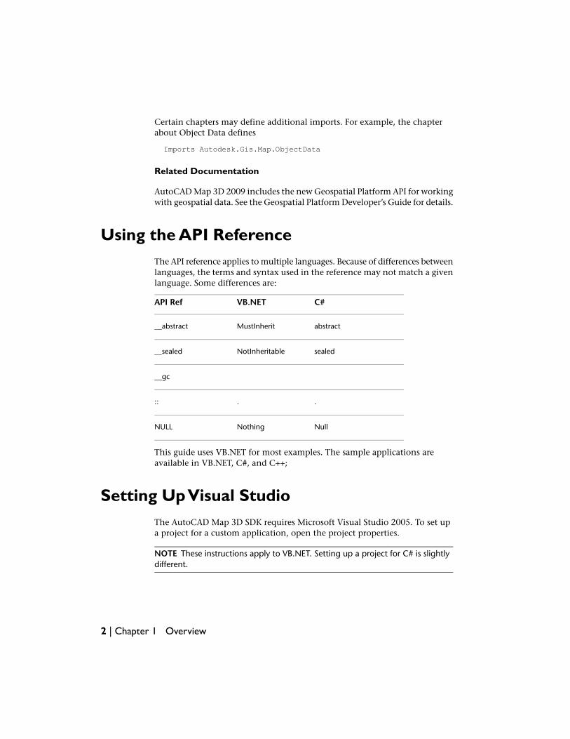
Certain chapters may define additional imports. For example, the chapterabout Object Data defines
Imports Autodesk.Gis.Map.ObjectData
Related Documentation
AutoCAD Map 3D 2009 includes the new Geospatial Platform API for workingwith geospatial data. See the Geospatial Platform Developer’s Guide for details.
Using the API ReferenceThe API reference applies to multiple languages. Because of differences betweenlanguages, the terms and syntax used in the reference may not match a givenlanguage. Some differences are:
C#VB.NETAPI Ref
abstractMustInherit__abstract
sealedNotInheritable__sealed
__gc
..::
NullNothingNULL
This guide uses VB.NET for most examples. The sample applications areavailable in VB.NET, C#, and C++;
Setting Up Visual StudioThe AutoCAD Map 3D SDK requires Microsoft Visual Studio 2005. To set upa project for a custom application, open the project properties.
NOTE These instructions apply to VB.NET. Setting up a project for C# is slightlydifferent.
2 | Chapter 1 Overview
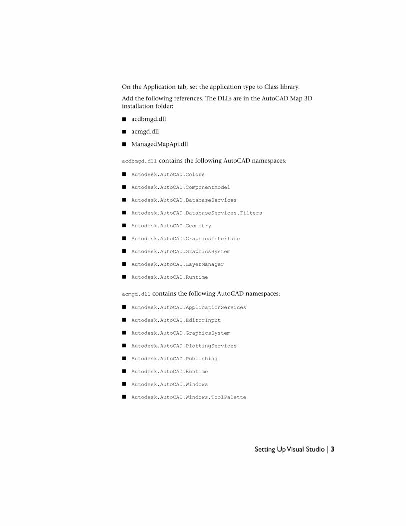
On the Application tab, set the application type to Class library.
Add the following references. The DLLs are in the AutoCAD Map 3Dinstallation folder:
■ acdbmgd.dll
■ acmgd.dll
■ ManagedMapApi.dll
acdbmgd.dll contains the following AutoCAD namespaces:
■ Autodesk.AutoCAD.Colors
■ Autodesk.AutoCAD.ComponentModel
■ Autodesk.AutoCAD.DatabaseServices
■ Autodesk.AutoCAD.DatabaseServices.Filters
■ Autodesk.AutoCAD.Geometry
■ Autodesk.AutoCAD.GraphicsInterface
■ Autodesk.AutoCAD.GraphicsSystem
■ Autodesk.AutoCAD.LayerManager
■ Autodesk.AutoCAD.Runtime
acmgd.dll contains the following AutoCAD namespaces:
■ Autodesk.AutoCAD.ApplicationServices
■ Autodesk.AutoCAD.EditorInput
■ Autodesk.AutoCAD.GraphicsSystem
■ Autodesk.AutoCAD.PlottingServices
■ Autodesk.AutoCAD.Publishing
■ Autodesk.AutoCAD.Runtime
■ Autodesk.AutoCAD.Windows
■ Autodesk.AutoCAD.Windows.ToolPalette
Setting Up Visual Studio | 3
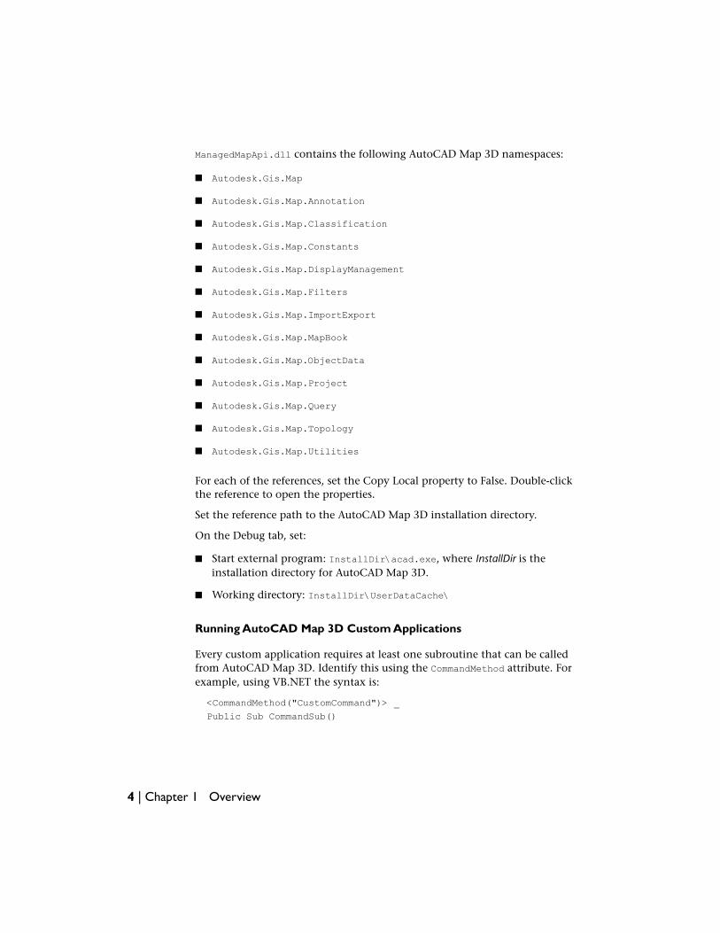
ManagedMapApi.dll contains the following AutoCAD Map 3D namespaces:
■ Autodesk.Gis.Map
■ Autodesk.Gis.Map.Annotation
■ Autodesk.Gis.Map.Classification
■ Autodesk.Gis.Map.Constants
■ Autodesk.Gis.Map.DisplayManagement
■ Autodesk.Gis.Map.Filters
■ Autodesk.Gis.Map.ImportExport
■ Autodesk.Gis.Map.MapBook
■ Autodesk.Gis.Map.ObjectData
■ Autodesk.Gis.Map.Project
■ Autodesk.Gis.Map.Query
■ Autodesk.Gis.Map.Topology
■ Autodesk.Gis.Map.Utilities
For each of the references, set the Copy Local property to False. Double-clickthe reference to open the properties.
Set the reference path to the AutoCAD Map 3D installation directory.
On the Debug tab, set:
■ Start external program: InstallDir\acad.exe, where InstallDir is theinstallation directory for AutoCAD Map 3D.
■ Working directory: InstallDir\UserDataCache\
Running AutoCAD Map 3D Custom Applications
Every custom application requires at least one subroutine that can be calledfrom AutoCAD Map 3D. Identify this using the CommandMethod attribute. Forexample, using VB.NET the syntax is:
<CommandMethod("CustomCommand")> _
Public Sub CommandSub()
4 | Chapter 1 Overview
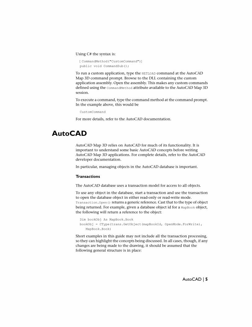
Using C# the syntax is:
[CommandMethod("CustomCommand")]
public void CommandSub();
To run a custom application, type the NETLOAD command at the AutoCADMap 3D command prompt. Browse to the DLL containing the customapplication assembly. Open the assembly. This makes any custom commandsdefined using the CommandMethod attribute available to the AutoCAD Map 3Dsession.
To execute a command, type the command method at the command prompt.In the example above, this would be
CustomCommand
For more details, refer to the AutoCAD documentation.
AutoCADAutoCAD Map 3D relies on AutoCAD for much of its functionality. It isimportant to understand some basic AutoCAD concepts before writingAutoCAD Map 3D applications. For complete details, refer to the AutoCADdeveloper documentation.
In particular, managing objects in the AutoCAD database is important.
Transactions
The AutoCAD database uses a transaction model for access to all objects.
To use any object in the database, start a transaction and use the transactionto open the database object in either read-only or read-write mode.Transaction.Open() returns a generic reference. Cast that to the type of objectbeing returned. For example, given a database object id for a MapBook object,the following will return a reference to the object:
Dim bookObj As MapBook.Book
bookObj = CType(trans.GetObject(mapBookId, OpenMode.ForWrite),
MapBook.Book)
Short examples in this guide may not include all the transaction processing,so they can highlight the concepts being discussed. In all cases, though, if anychanges are being made to the drawing, it should be assumed that thefollowing general structure is in place:
AutoCAD | 5
Dim trans As Transaction = Nothing
Dim docs As DocumentCollection = Application.DocumentManager
Dim activeDoc As Document = docs.MdiActiveDocument
Try
trans = activeDoc.TransactionManager.StartTransaction()
'
' Open object(s)
'
Dim bookObj As MapBook.Book
bookObj = CType(trans.GetObject(mapBookId, OpenMode.ForWrite),
MapBook.Book)
'
' Insert code to process transaction
'
' Commit transaction
'
trans.Commit()
Catch
'
' Handle exception, and cancel transaction
'
Finally
trans.Dispose()
End Try
Although transactions can be nested, this is not recommended. Onecomplication is that adding an entity takes place immediately, but removingan entity does not take effect until the transaction has been committed.
NOTE Many examples in this guide assume that activeDoc refers to the activedocument.
6 | Chapter 1 Overview

Session and Project
OverviewAn AutoCAD Map 3D session represents the active state of the Map 3Dapplication.
Most of the classes for working with the session are defined in theAutodesk.Gis.Map namespace.
There is a single instance of the Map application, available through theApplication property of the abstract class
Autodesk.Gis.Map.HostMapApplicationServices
This returns a MapApplication object that represents the entire application. Ithas some read-only properties that provide access to objects in the session. Oneof the main properties is Projects.
Projects returns a collection of all open projects, a ProjectCollection objectin the Autodesk.Gis.Map.Project namespace. A project is represented by aProjectModel object. A project is the container for a Map 3D drawing and allits associated objects. Nearly all interaction with a drawing begins with a project.
ActiveProject returns the ProjectModel for the currently active project.
NOTE For historical reasons, the API uses the term project where the user interfacewill normally use map or drawing.
For example, the following gets the current project:
2
7
Dim mapApp As MapApplication
mapApp = HostMapApplicationServices.Application
Dim activeProj As Project.ProjectModel
activeProj = mapApp.ActiveProject
The following processes all open projects:
Dim mapApp As MapApplication
mapApp = HostMapApplicationServices.Application
Dim projList As Project.ProjectCollection
projList = mapApp.Projects
For Each project As Project.ProjectModel In projList
' Process projects
Next
NOTE Many of the examples in this guide assume that mapApp and activeProjhave already been defined as in the example above.
A project is closely related to an AutoCAD drawing. In AutoCAD Map 3D,opening a drawing automatically creates a new project. You cannot instantiatea new project directly.
MapApplication.GetDocument() returns the AutoCAD document associatedwith a project. Conversely, Project.ProjectCollection.GetProject() returnsthe ProjectModel for an AutoCAD document.
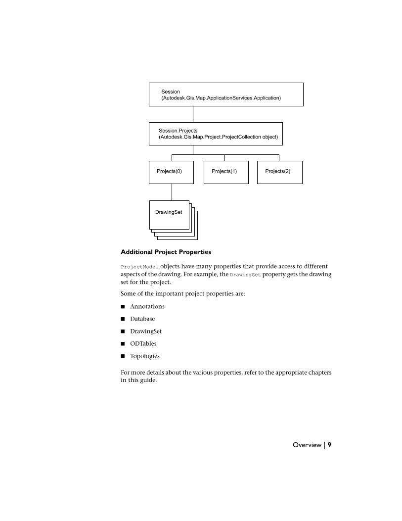
For example, the following diagram shows a session that has three openprojects. The first project refers to external drawings in its drawing set. Anyone of the projects could be active at one time. Each project has acorresponding AutoCAD drawing.
8 | Chapter 2 Session and Project
Session(Autodesk.Gis.Map.ApplicationServices.Application)
Session.Projects(Autodesk.Gis.Map.Project.ProjectCollection object)
Projects(0) Projects(1) Projects(2)
DrawingSet
Additional Project Properties
ProjectModel objects have many properties that provide access to differentaspects of the drawing. For example, the DrawingSet property gets the drawingset for the project.
Some of the important project properties are:
■ Annotations
■ Database
■ DrawingSet
■ ODTables
■ Topologies
For more details about the various properties, refer to the appropriate chaptersin this guide.
Overview | 9
AutoCAD Database
The ProjectModel.Database property returns a reference to the AutoCADdatabase. This is necessary for many AutoCAD operations.
Project Options
The ProjectModel.Options property returns a reference to the project’s options.
Drawing ObjectsDrawing objects are the visible items in an AutoCAD drawing.
NOTE The AutoCAD developer documentation generally uses the term entity orAcDb entity when discussing drawing objects.
In the AutoCAD API, an Autodesk.AutoCAD.DatabaseServices.DBObjectobject represents any object in the drawing database, including drawingobjects. A DBObject can be referred to by either:
■ Autodesk.AutoCAD.DatabaseServices.Handle
■ Autodesk.AutoCAD.DatabaseServices.ObjectID
A Handle is a persistent identifier that is stored with the AutoCAD databasewhen it is saved. Each handle is unique within a single drawing, but differentdrawings are likely to have duplicate handles referring to separate objects.
An ObjectID is used for quick access to drawing objects within an AutoCADsession. They are not persistent, though. They expire when the drawing isclosed.
Map Objects
Because a single AutoCAD Map 3D project can include more than oneAutoCAD drawing, an AutoCAD handle is not sufficient to uniquely identifyan object.
A MapObjectId, defined in the namespace Autodesk.Gis.Map.Utilities,identifies an object by its AutoCAD handle and by its drawing identifier. TheMapObjectId.ObjectHandle property is the AutoCAD handle, andMapObjectId.DrawingId is the drawing identifier, an object of typeUtilities.MapId.
10 | Chapter 2 Session and Project
Object Data
IntroductionObject data provides a way of attaching additional information to drawingobjects. It is more powerful and flexible than AutoCAD block attributes becauseobject data can be attached to any object in a drawing.
NOTE Object data can only be attached to drawing objects. FDO feature sourceshave a different way to handle feature properties.
The classes for handling object data are mostly within the ObjectDatanamespace. Code in this chapter assumes the following:
Imports Autodesk.Gis.Map.ObjectData
Tables
Internally, object data is stored in tables. Each drawing has its own set of tables,available from the ProjectModel.ODTables property. This returns an object oftype ObjectData.Tables.
For example, if mapApp is the Map application, the following will get the objectdata tables for the active drawing:
Dim activeProject As Project.ProjectModel = mapApp.ActiveProject
Dim tableList As ObjectData.Tables = activeProject.ODTables
ObjectData.Tables.GetTableNames() returns a list of the table names that havebeen defined for the drawing.
3
11
To get a single table from the set of tables, use the ObjectData.Tables.Itemproperty. Note that this requires a table name as a parameter, not a tablenumber. For example:
Dim table As ObjectData.Table = tableList.Item("table1")
or
Dim table As ObjectData.Table = tableList("table1")
Use Tables.IsTableDefined() to see if a table name exists. An attempt to geta table that does not exist throws an exception.
Field Definitions
Columns in a table are defined by ObjectData.FieldDefinition objects, whichdescribe the data type and default value. The data types are defined in theConstants.DataType enum:
■ UnknownType
■ Integer
■ Real
■ Character
■ Point
Records
Each row in the table is of type ObjectData.Record. Every record in the tableis associated with a drawing object.
The Item property of an ObjectData.Record contains the values for the record,one for each field definition in the table. Each item is of typeUtilities.MapValue, which is a general-purpose class for storing data.
Creating a TableCreating a table requires:
■ Creating an ObjectData.FieldDefinitions object
■ Adding field definitions for every column in the table
12 | Chapter 3 Object Data
■ Creating the table by adding the field definitions to the ODTables objectfor the drawing
Create an ObjectData.FieldDefinitions object using theProjectModel.MapUtility.NewODFieldDefinitions() method. Add fieldsusing the FieldDefinitions.Add() method. For example, if mapApp is the Mapapplication, the following creates field definitions for 2 columns:
Dim fieldDefs As ObjectData.FieldDefinitions
fieldDefs = _
mapApp.ActiveProject.MapUtility.NewODFieldDefinitions()
Dim def1 As ObjectData.FieldDefinition
def1 = fieldDefs.Add("FIRST_FIELD", "Owner name", _
Autodesk.Gis.Map.Constants.DataType.Character, 0)
def1.SetDefaultValue("A")
Dim def2 As ObjectData.FieldDefinition
def2 = fieldDefs.Add("SECOND_FIELD", "Assessment year", _
Autodesk.Gis.Map.Constants.DataType.Integer, 1)
def2.SetDefaultValue(0)
Get a reference to the ODTables property for the drawing, and add the fielddefintions to create a new table.
Dim tables As ObjectData.Tables
tables = mapApp.ActiveProject.ODTables
tables.Add("NewTable", fieldDefs, "Description", True)
Get a reference to the table using Tables.Item(). This expects a stringparameter.
Dim table As ObjectData.Table
table = tables("NewTable")
Removing a Table
To remove a table, get a reference to the ODTables property for the drawing,and call Tables.RemoveTable().
Dim tables As ObjectData.Tables
tables = mapApp.ActiveProject.ODTables
tables.RemoveTable("NewTable")
Creating a Table | 13

Attaching Object DataAdding object data to a drawing object requires:
■ Creating an empty record
■ Initializing the record with correct types for the table
■ Setting values for each column
■ Attaching the object data by adding the record to the table
Create an empty record using the static method ObjectData.Record.Create().This does not define any fields for the record. Initialize the record, whichcreates fields of the correct type, using Table.InitRecord().
Dim rec As ObjectData.Record
rec = ObjectData.Record.Create()
table.InitRecord(rec)
Each Item property in the record is of type Utilities.MapValue, which is ageneral-purpose class for storing data of variant types. To set any field, get areference to the field from the Record object using the Item property. Assignthe value with MapValue.Assign(). For example, if rec is a record in a tablewhere the second field is of type integer, the following will assign a value of10 to the field.
Dim val As Utilities.MapValue
val = rec(1)
val.Assign(10)
Add the record to the table with Table.AddRecord() and associate it with anobject. This requires a Record and either an AutoCAD DBObject or ObjectIdas parameters.
newTable.AddRecord(rec, objId)
A single drawing object may have more than one object data record in a giventable.
Getting Object DataTo get all object data records from a single table for a drawing object:
■ Get the ObjectData.Tables object for the drawing.
14 | Chapter 3 Object Data
■ Get the individual table.
■ Get the ObjectData.Records collection for the object, using one of theGetObjectTableRecords() methods.
■ Iterate through the records in the collection.
■ Process the fields in each record.
The following example writes the values from table for objId to the console.
Dim fieldDefs As ObjectData.FieldDefinitions = _
table.FieldDefinitions
Dim recs As ObjectData.Records
recs = table.GetObjectTableRecords(0, objId, _
Constants.OpenMode.OpenForRead, True)
If (recs.Count() > 0) Then
For Each rec As ObjectData.Record In recs
For i As Integer = 0 To rec.Count() - 1
Dim val As Autodesk.Gis.Map.Utilities.MapValue
val = rec(i)
Dim fieldDef As ObjectData.FieldDefinition
fieldDef = fieldDefs(i)
acEditor.WriteMessage(
vbNewLine + fieldDef.Name + ": ")
Select Case val.Type
Case Constants.DataType.Character
acEditor.WriteMessage(val.StrValue)
Case Constants.DataType.Integer
acEditor.WriteMessage(val.Int32Value.ToString)
Case Constants.DataType.Point
acEditor.WriteMessage("point")
Case Constants.DataType.Real
acEditor.WriteMessage(val.DoubleValue.ToString)
Case Else
acEditor.WriteMessage("undefined")
End Select
Next
Next
End If
recs.Dispose()
Processing all tables for an object is similar. Instead of callingTable.GetObjectTableRecords() for an individual table, call
Getting Object Data | 15
Tables.GetObjectRecords() for all tables. When processing the fields, be sureto to get the field definitions from the correct table for the current record.
■ Get the ObjectData.Tables object for the drawing.
■ Get the ObjectData.Records collection for the object, using one of theGetObjectRecords() methods.
■ Iterate through the records in the collection.
■ Get the table name for the current record.
■ Get the fields definitions for the table.
■ Process the fields in each record.
NOTE When you have finished processing the records, release any of the disposableobjects with their Dispose() methods. This applies to any classes inheritingAutodesk.AutoCAD.Runtime.DisposableWrapper, like ObjectData.Table,ObjectData.Records, or Utilities.MapValue.
Updating and Deleting RecordsTo update or delete records, they must be opened for write access in the callto Table.GetObjectTableRecords() or Tables.GetObjectRecords().
Fields in a record are of type Utilities.MapValue. To update a field, get areference to the value from the Record object. Assign a new value usingMapValue.Assign() and update the record using Records.UpdateRecord().The following example sets the value of the first field in a record:
Dim val As Utilities.MapValue = rec(0)
val.Assign(19)
recs.UpdateRecord(rec)
To delete a record, get an IEnumerator using Records.GetEnumerator().Advance the enumerator to the record to be deleted and callRecords.RemoveRecord(). The following example deletes the first record foran object.
16 | Chapter 3 Object Data

Dim recs As ObjectData.Records
recs = table.GetObjectTableRecords(0, objId, _
Constants.OpenMode.OpenForWrite, True)
Dim ie As IEnumerator
ie = recs.GetEnumerator()
ie.MoveNext()
recs.RemoveRecord()
recs.Dispose()
Updating and Deleting Records | 17

18
Data Connect
OverviewThe Data Connect API can be used to create plugins for the Data Connect dialog.Use this to create new connection forms for FDO providers, either providersthat are installed with AutoCAD Map 3D or additional providers.
NOTE The Data Connect API is not part of the Geospatial Platform API. It is, however,included in the technical preview for this release of AutoCAD Map 3D. For thatreason it is documented in this guide instead of the .NET Developer’s Guide.
If a custom plugin works with a provider installed with AutoCAD Map 3D, itreplaces the existing form for the provider. For example, a custom form for theAutodesk Oracle provider could look like the following. The outlined area is thecustom form, embedded in the Data Connect dialog.
4
19

To add a new option to the Data Connect dialog, complete the followingsteps:
■ Ensure the FDO provider DLL is installed with AutoCAD Map 3D.
■ Ensure the FDO provider is listed in providers.xml.
■ Create the plugin to use the provider.
■ Save the plugin DLL in the Plugins\DataConnect folder of the AutoCADMap 3D installation. If the folder does not exist, create it.
providers.xml is located in the FDO\bin folder of the AutoCAD Map 3Dinstallation. It contains entries for each available FDO provider.
Setting Up Visual StudioTo create a project using the Data Connect API, follow the instructions in theAutoCAD Map 3D .NET Developer’s Guide. Add the following references tothe project:
■ Autodesk.Gis.Plugins.dll
■ AcMapDataConnectPlugins.dll
20 | Chapter 4 Data Connect
The assemblies are located in the AutoCAD Map 3D installation folder.
Creating the Plugin
NOTE To ensure the plugin is loaded, place the DLL in the Plugins\DataConnectfolder under the AutoCAD Map 3D installation folder. Plugins in this folder thatfollow the proper structure are loaded on demand. There is no need to run thenetload command.
Using Visual Studio, create a new project. Add a UserControl to the project.The control will be embedded in the Data Connect dialog.
The plugin class must implement the IDataConnectConnectionPlugin interface.It also requires a DataConnectPluginAttribute with the FDO provider name.The provider name must match the name in providers.xml. For example:
[DataConnectPluginAttribute("Autodesk.Oracle.3.1")]
public partial class SampleProviderConnectUIPlugin
: UserControl
, IDataConnectConnectionPlugin
{
IDataConnectConnectionPlugin provides the necessary methods for AutoCADMap 3D to interact with the control. It inherits 2 other interfaces:IDataConnectPlugin and IPlugin.
The implementation for IDataConnectPlugin can be simple, as follows. TheIDataConnectPluginHost interface contains a single property, HostApplication,of type object. When attached, it contains a reference to the host applicationobject,Autodesk.AutoCAD.ApplicationServices.Application.AcadApplication.
Creating the Plugin | 21

// IDataConnectPlugin implementation
protected IDataConnectPluginHost _host;
protected string _providerName;
public void Attach(IDataConnectPluginHost host)
{
_host = host;
}
public void Detach() { _host = null; }
public IDataConnectPluginHost Host
{
get { return _host; }
}
public UserControl ClientControl
{
get { return this; }
}
Similarly, the implementation for IPlugin needs methods to get and setproperties. The properties are used to describe the plugin. They may bedisplayed to the user and should be localized. The Dependencies property isnot currently used.
22 | Chapter 4 Data Connect
// IPlugin implementation
protected string title = "title";
protected string description = "description";
protected string company = "company";
protected string version = "3.0.0";
protected Type[] dependencies;
public string Title
{
get { return title; }
set { title = value; }
}
public string Description
{
get { return description; }
set { description = value; }
}
public string Company
{
get { return company; }
set { company = value; }
}
public string Version
{
get { return version; }
set { version = value; }
}
public Type[] Dependencies
{
get { return dependencies; }
}
IDataConnectConnectionPlugin contains methods to get and set theconnection parameters for the FDO provider, so the implementation dependson the requirements of the provider. For complete details about the methods,refer to the AutoCAD Map 3D .NET API Reference Supplement. Generallythese methods will work with fields on the custom form.
Creating the Plugin | 23
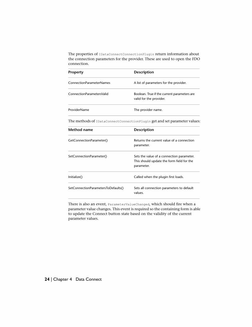
The properties of IDataConnectConnectionPlugin return information aboutthe connection parameters for the provider. These are used to open the FDOconnection.
DescriptionProperty
A list of parameters for the provider.ConnectionParameterNames
Boolean. True if the current parameters arevalid for the provider.
ConnectionParametersValid
The provider name.ProviderName
The methods of IDataConnectConnectionPlugin get and set parameter values:
DescriptionMethod name
Returns the current value of a connectionparameter.
GetConnectionParameter()
Sets the value of a connection parameter.This should update the form field for theparameter.
SetConnectionParameter()
Called when the plugin first loads.Initialize()
Sets all connection parameters to defaultvalues.
SetConnectionParametersToDefaults()
There is also an event, ParameterValueChanged, which should fire when aparameter value changes. This event is required so the containing form is ableto update the Connect button state based on the validity of the currentparameter values.
24 | Chapter 4 Data Connect
Annotation
OverviewAnnotations provide a way to label drawing objects, based on data associatedwith the objects. The associated data can come from various places, such asobject data, linked databases, or object properties. For example, if a drawingcontains parcels, and the parcels have object data with the name of the parcelowner or the most recent sale price of the parcel, then these values could beadded to the map as part of an annotation.
Each annotation is based on an annotation template, which is a special blockin the drawing. The template describes the annotation, and usually containsannotation text defining the variable content.
A new annotation is created by inserting a reference to the annotation template.This creates a reference to the annotation block, substituting the proper valuesin the expression fields.
The classes for handling annotations are mostly within the Annotationnamespace. Code in this chapter assumes the following:
Imports Autodesk.Gis.Map.Annotation
Annotation TemplatesAn annotation template is a special block in the drawing. It defines the fixedand variable parts of the annotation.
NOTE For more information about blocks, refer to the AutoCAD developerdocumentation.
5
25
Internally, annotation templates use a special naming convention. The namesof all blocks containing annotation templates begin withACMAP_ANN_TEMPLATE_. This prefix is defined in theAnnotations.TemplateNameBlockTableRecordPrefix property.
Annotation API calls, though, use the annotation name as it appears in theUI. For example, an annotation template named ParcelName would be storedin a block named ACMAP_ANN_TEMPLATE_ParcelName, but it would be createdwith a call to Annotations.CreateAnnotationTemplate("ParcelName").
The ProjectModel.Annotations property returns an Annotations object thatcan be used for managing the annotations and annotation templates.
Attributes
An AutoCAD block can contain attribute definitions, which are text entitiesthat can define informational text for each block reference.
In an annotation template, attribute definitions are used to define the variableparts of the annotation. For example, if the annotations include object data,then attribute definitions in the block template define what object data shouldappear and how it will be displayed.
The AttributeDefinition class inherits the DBText class, which inherits theEntity class. These have properties such as Color and Height that define howthe annotation will appear in the drawing. For example, to set the text heightfor an annotation, set the Height property of the attribute definition used forthe annotation.
NOTE The properties used for the attribute definition can also be modified usingexpression strings. See Expressions in Annotations (page 28) for details.
Creating an Annotation Template
Although an annotation template is a form of AutoCAD block, it must becreated using the Map API or it will not be recognized properly.
■ Start a transaction.
■ Create the annotation template usingAnnotations.CreateAnnotationTemplate().
■ Get a reference to the annotation template using Annotations.Item().
■ If required, set block properties for the annotation template usingAnnotationTemplate.SetExpressionString(). For example, this can be
26 | Chapter 5 Annotation
used to rotate the block reference to match the rotation of the object beingannotated.
■ If required, add fixed drawing objects to the annotation template. Get theAutoCAD block id using the AnnotationTemplate.BlockDefinitionIdproperty and add drawing objects to the template using standard AutoCADAPI calls.
■ Add variable annotation text to the template usingAnnotationTemplate.CreateAnnotationText(). This creates an attributedefinition in the block.
■ Set the display properties of the annotation text by setting properties forthe attribute definition.
■ Set the expression string for the annotation text usingAnnotations.SetExpressionString().
■ Commit the transaction.
Annotations.CreateAnnotationTemplate() creates an empty template. Itreturns an AutoCAD ObjectID that is the id of the block table record. Get areference to the annotation template object using Annotations.Item().
Dim annotations As Annotation.Annotations = _
activeProj.Annotations
Dim trans As Transaction = Nothing
trans = activeDoc.TransactionManager.StartTransaction()
Dim newTemplateId As ObjectId = _
annotations.CreateAnnotationTemplate("templateName")
Dim newTemplate As Annotation.AnnotationTemplate = _
annotations(newTemplateId)
If required, set block properties for the annotation template. See Expressionsin Annotations (page 28) for details.
newTemplate.SetExpressionString(_
Annotation.AnnotationExpressionFields.BlockRotation, ".ANGLE")
Add objects to the template. They can be normal drawing objects or annotationtext.
To add normal drawing objects, use standard AutoCAD methods.
Annotation Templates | 27
Dim line As New Line
line.StartPoint = New Geometry.Point3d(0.0, -0.6, 0.0)
line.EndPoint = New Geometry.Point3d(2.0, -0.6, 0.0)
Dim blockTableRec As BlockTableRecord
blockTableRec = newTemplateId.GetObject(OpenMode.ForWrite)
blockTableRec.AppendEntity(line)
trans.AddNewlyCreatedDBObject(line, True)
To add annotation text, create an annotation text object. This is a special typeof AutoCAD attribute definition. AnnotationTemplate.CreateAnnotationText()returns the AutoCAD ObjectId of the attribute definition. Open this objectfor writing and cast to an AttributeDefinition object:
Dim expressionTextId As ObjectId
expressionTextId = newTemplate.CreateAnnotationText()
Dim attDef As AttributeDefinition
attDef = _
CType(trans.GetObject(expressionTextId, OpenMode.ForWrite), _
AttributeDefinition)
Most of the properties for the annotation template can be set using theAttributeDefinition properties. For example:
attDef.Position = _
New Autodesk.AutoCAD.Geometry.Point3d(0.0, 0.0, 0.0)
attDef.Tag = "testTag"
attDef.Height = 0.5
attDef.VerticalMode = TextVerticalMode.TextVerticalMid
attDef.HorizontalMode = TextHorizontalMode.TextCenter
attDef.AlignmentPoint =
New Autodesk.AutoCAD.Geometry.Point3d(0.0, 0.0, 0.0)
The annotation text must be set using Annotations.SetExpressionString().See Expressions in Annotations (page 28) for details.
Expressions in AnnotationsUse expressions to set the text or the display properties of the annotation.Some of the items that can use expressions are:
■ Annotation text
■ Text color
■ Text size
28 | Chapter 5 Annotation
■ Rotation angle
■ Position relative to the drawing object being annotated
NOTE Properties in an attribute definition can be overridden by annotationexpressions. For example, if the attribute definition defines the location of the text,the annotation expression could override it.
AnnotationTemplate.SetExpressionString() sets properties for the entiretemplate. Annotations.SetExpressionString() sets properties for annotationtext within the block.
Expressions are evaluated by the AutoLISP interpreter, and return a singlevalue. Depending on the property being set, the value can be numeric orstring. If the expression cannot be evaluated properly it displays the attributetag name instead.
NOTE For more details about expressions, including a list of functions and variables,see the Map 3D Help. In the Reference Guide section there is a chapter about theExpression Evaluator.
The enum Annotation.AnnotationExpressionFields contains the completelist of fields that can use expressions.
In most cases, expressions are used to define the text of the annotation, butthey can also be used to define things like color, size, or position.
Example
To set the annotation text based on object data, use the syntax:fieldname@tablename. For example:
Imports Autodesk.Gis.Map.Annotation
annotations.SetExpressionString(attDef, _
AnnotationExpressionFields.AttributeDefinitionAnnotationString, _
":PARCEL_OWNER@ParcelData")
Inserting AnnotationsTo insert an annotation, call one of theAnnotationTemplate.InsertReference() methods. They all require anObjectId or ObjectIdCollection as parameter, to identify the drawing objectsto be annotated.
Inserting Annotations | 29
This creates a block reference in the drawing. It evaluates the annotationexpressions and uses the results to set the text or other properties of thereference.
An inserted annotation reference can also have overrides that change thedisplay properties. See Annotation Overrides (page 30) for details.
Updating and Refreshing AnnotationsOnce inserted, annotation references do not change unless they are explicitlychanged. For example, if the object data for a drawing object changes, anyanotations that use the object data will still display the original value.
There are two operations for revising existing annotation references:
■ Updating
■ Refreshing
Updating removes and recreates all the annotations that use a template.Refreshing re-evaluates the annotation expressions, but does not removeout-of-date annotations.
To update annotations, call AnnotationTemplate.UpdateReferences().
newTemplate.UpdateReferences(True)
To refresh annotations, call AnnotationTemplate.RefreshReferences().
newTemplate.RefreshReferences(True)
Annotation OverridesAn annotation override can be applied when an annotation reference is created.It changes selected properties of the annotation template. For example, anannotation override can change the color or text size of the annotation.
Annotation overrides can apply to the static properties of the annotation,which are set using the AttributeDefinition properties, or the dynamicproperties, which are set using expressions.
Annotation overrides correspond to the Insert Options and Insert Propertiesof the Insert Annotation dialog in the UI.
30 | Chapter 5 Annotation

For example, to override the static color, set the ColorOverride property ofthe annotation override. To override a color set using an expression, set theColorExpressionOverride property.
To apply an annotation override, insert the annotation usingAnnotationTemplate(ObjectId, AnnotationOverrides). For example:
Dim annOverrides As New Annotation.AnnotationOverrides
annOverrides.Clear()
Dim greenClr As Autodesk.AutoCAD.Colors.Color = _
Autodesk.AutoCAD.Colors.Color.FromColorIndex( _
Autodesk.AutoCAD.Colors.ColorMethod.None, 3)
annOverrides.ColorOverride = greenClr
annTemplate.InsertReference(objId, annOverrides)
Annotation Overrides | 31

32
Events
OverviewEvents and event handlers provide a way for applications to respond to changesin the Map application. For example, opening a new project can fire an eventhandler to perform additional processing.
The API uses standard .NET mechanisms for handling events. Applicationswanting to handle events subscribe to the events. When the event is fired allhandlers subscribed to that event are called.
Event handlers accept two parameters:
■ A reference to the object raising the event
■ Event arguments
The class definition for the event arguments is usually specific to the eventbeing handled.
Events in the API ReferenceFor every event, the AutoCAD Map 3D API Reference contains the following:
■ Class definition for the event arguments. The names of these classes usuallybegin with the event name and end with “EventArgs”. In some cases theevent uses System.EventArgs instead of defining a new class.
6
33
■ Methods for adding and removing event handlers. The names of thesemethods begin with “add_” or “remove_”. Do not call these methodsdirectly. Instead use the correct syntax for the language.
■ Type definition for the event handler.
NOTE Some events, such as ProjectModel.BeginClose, useSystem.EventHandler and System.EventArgs instead of objects derived fromthem. For details refer to the API reference or the Visual Studio Object Browser.
For example, the ProjectOpened event in the Autodesk.Gis.Map namespaceconsists of the following:
■ ProjectOpenedEventArgs class
■ add_ProjectOpened method in the MapApplication class
■ remove_ProjectOpened method in the MapApplication class
■ ProjectOpenedEventHandler type
NOTE The actual event name is not used in the API reference. It can always beinferred from the corresponding add_ or remove_ methods.
Example:VB.NET
To define an event handler for the ProjectOpened event, create a subroutine:
Sub handleProjectOpened(ByVal pSender As Object, _
ByVal pArgs As ProjectOpenedEventArgs)
' Insert code to handle event
End Sub
To subscribe to the event:
AddHandler mapApp.ProjectOpened, AddressOf handleProjectOpened
To unsubscribe from the event:
RemoveHandler mapApp.ProjectOpened, AddressOf handleProjectOpened
Example: C#
To define an event handler for the ProjectOpened event, create a subroutine:
34 | Chapter 6 Events
void handleProjectOpened(Object sender,
ProjectOpenedEventArgs args)
{
// Insert code to handle event
}
To subscribe to the event:
mapApp.ProjectOpened += new ProjectOpenedEventHandler(
handleProjectOpened);
To unsubscribe from the event:
mapApp.ProjectOpened -= new ProjectOpenedEventHandler(
handleProjectOpened);
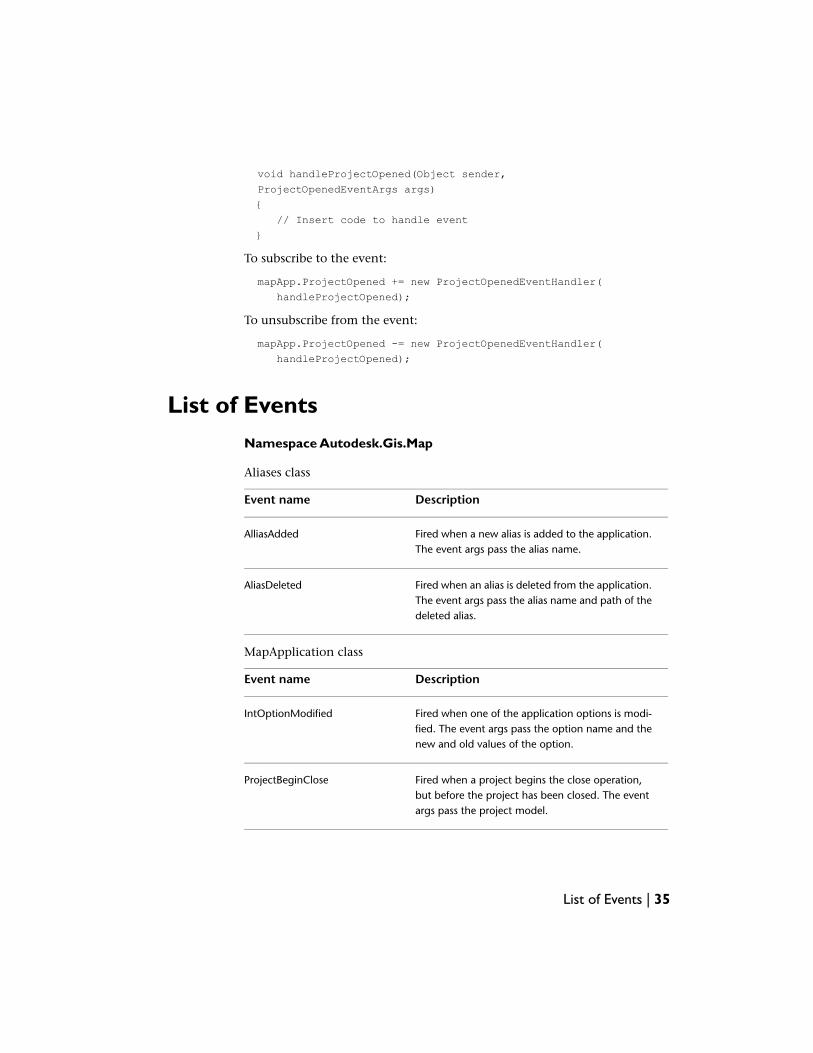
List of EventsNamespace Autodesk.Gis.Map
Aliases class
DescriptionEvent name
Fired when a new alias is added to the application.The event args pass the alias name.
AlliasAdded
Fired when an alias is deleted from the application.The event args pass the alias name and path of thedeleted alias.
AliasDeleted
MapApplication class
DescriptionEvent name
Fired when one of the application options is modi-fied. The event args pass the option name and thenew and old values of the option.
IntOptionModified
Fired when a project begins the close operation,but before the project has been closed. The eventargs pass the project model.
ProjectBeginClose
List of Events | 35
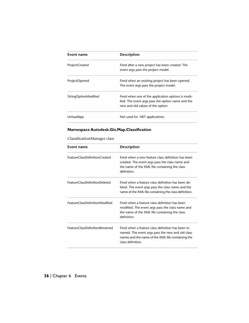
DescriptionEvent name
Fired after a new project has been created. Theevent args pass the project model.
ProjectCreated
Fired when an existing project has been opened.The event args pass the project model.
ProjectOpened
Fired when one of the application options is modi-fied. The event args pass the option name and thenew and old values of the option.
StringOptionModified
Not used for .NET applications.UnloadApp
Namespace Autodesk.Gis.Map.Classification
ClassificationManager class
DescriptionEvent name
Fired when a new feature class definition has beencreated. The event args pass the class name and
FeatureClassDefinitionCreated
the name of the XML file containing the classdefinition.
Fired when a feature class definition has been de-leted. The event args pass the class name and thename of the XML file containing the class definition.
FeatureClassDefinitionDeleted
Fired when a feature class definition has beenmodified. The event args pass the class name and
FeatureClassDefinitionModified
the name of the XML file containing the classdefinition.
Fired when a feature class definition has been re-named. The event args pass the new and old class
FeatureClassDefinitionRenamed
names and the name of the XML file containing theclass definition.
36 | Chapter 6 Events

DescriptionEvent name
Fired when a new definition file is attached. Theevent args pass the filename.
FeatureDefinitionFileAttached
Fired when a definition file is modified. The eventargs pass the filename.
FeatureDefinitionFileModified
Namespace Autodesk.Gis.Map.DisplayManagement
DisplayManager class
DescriptionEvent name
CategoryAppended
CategoryModified
CategoryUnappended
MapAppended
MapGoodBye
Fired when changing the current display managermap, before the change is made. Returns
MapSetCurrentBegin
MapSetCurrentEnd
MapSetCurrentFails
MapUnappended
StyleAppendedToCategory
StyleModified
StyleUnappended
List of Events | 37
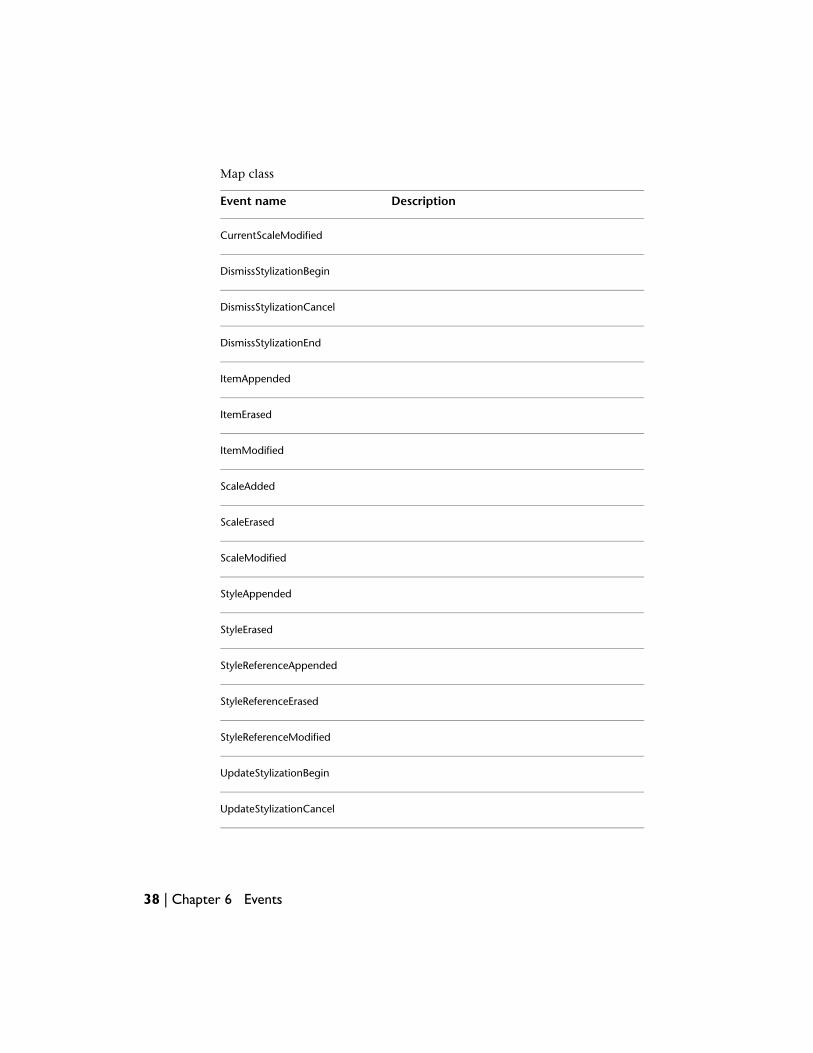
Map class
DescriptionEvent name
CurrentScaleModified
DismissStylizationBegin
DismissStylizationCancel
DismissStylizationEnd
ItemAppended
ItemErased
ItemModified
ScaleAdded
ScaleErased
ScaleModified
StyleAppended
StyleErased
StyleReferenceAppended
StyleReferenceErased
StyleReferenceModified
UpdateStylizationBegin
UpdateStylizationCancel
38 | Chapter 6 Events
DescriptionEvent name
UpdateStylizationEnd
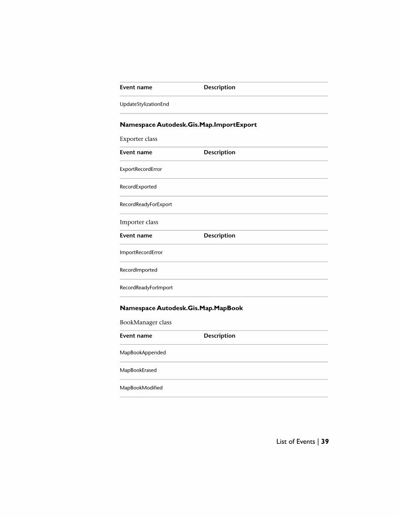
Namespace Autodesk.Gis.Map.ImportExport
Exporter class
DescriptionEvent name
ExportRecordError
RecordExported
RecordReadyForExport
Importer class
DescriptionEvent name
ImportRecordError
RecordImported
RecordReadyForImport
Namespace Autodesk.Gis.Map.MapBook
BookManager class
DescriptionEvent name
MapBookAppended
MapBookErased
MapBookModified
List of Events | 39
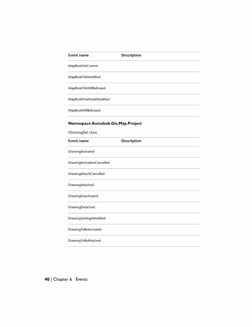
DescriptionEvent name
MapBookSetCurrent
MapBookTileModified
MapBookTileWillBeErased
MapBookTreeNodeModified
MapBookWillBeErased
Namespace Autodesk.Gis.Map.Project
DrawingSet class
DescriptionEvent name
DrawingActivated
DrawingActivationCancelled
DrawingAttachCancelled
DrawingAttached
DrawingDeactivated
DrawingDetached
DrawingSettingsModified
DrawingToBeActivated
DrawingToBeAttached
40 | Chapter 6 Events
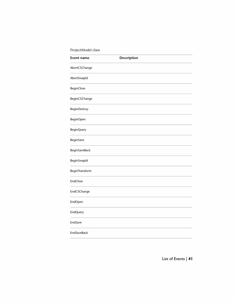
ProjectModel class
DescriptionEvent name
AbortCSChange
AbortSwapId
BeginClose
BeginCSChange
BeginDestroy
BeginOpen
BeginQuery
BeginSave
BeginSaveBack
BeginSwapId
BeginTransform
EndClose
EndCSChange
EndOpen
EndQuery
EndSave
EndSaveBack
List of Events | 41
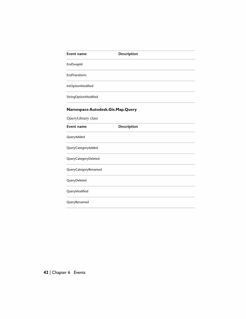
DescriptionEvent name
EndSwapId
EndTransform
IntOptionModified
StringOptionModified
Namespace Autodesk.Gis.Map.Query
QueryLibrary class
DescriptionEvent name
QueryAdded
QueryCategoryAdded
QueryCategoryDeleted
QueryCategoryRenamed
QueryDeleted
QueryModified
QueryRenamed
42 | Chapter 6 Events
Drawing Sets
OverviewDrawing sets provide a way for a single map to combine objects from multipledrawings. One drawing, the project drawing, can attach multiple sourcedrawings. The source drawings, in turn, can attach other source drawings toform a tree of attached drawings.
Running a query on the attached drawings copies selected objects into theproject drawing, where they can be displayed and edited. Unless an object froman attached drawing has been “queried in” it does not appear in the projectdrawing. See Queries and Save Sets (page 45) for more details.
Drive AliasesAttached drawings are often shared between different users on differentcomputers. Because of this, the paths to the attached drawings can be differentfor each user. Aliases help manage these files.
Each alias maps an alias name to a directory path. Each AutoCAD Map 3D usercan define different paths for the aliases. The locations of attached drawingsare always identified using the aliases, so users can have different paths to theatttached drawings, as long as the aliases are the same.
The DriveAlias class in the Autodesk.Gis.Map namespace represents anindividual alias. It has two properties: Name and Path.
The Aliases property of the map application returns an Aliases object formanaging the aliases in the session. Aliases.Item() returns an individual drivealias, either by alias name or index number.
7
43

Dim aliasList As Aliases
aliasList = mapApp.Aliases
Aliases objects have methods for adding and removing aliases, and eventhandlers for detecting when aliases have been added or removed.
Attaching and Detaching DrawingsAttaching a drawing adds it to the drawing set for a project. Detaching adrawing removes it from the drawing set.
To attach a drawing, use DrawingSet.AttachDrawing(). Pass a single stringargument that contains the alias and the path to the drawing to attach. Theform is:
alias:\filename
This returns a reference to the attached drawing, an AttachedDrawing object.
When an attached drawing is activated, the file is locked against editing byother applications. To remove the lock, but keep the drawing attached, callAttachedDrawing.Deactivate(). To reactivate the drawing, callAttachedDrawing.Activate().
44 | Chapter 7 Drawing Sets
Queries and Save Sets
OverviewQueries and save sets work on attached drawings. A query copies drawing objectsfrom attached drawings into the project drawing. Once in the project drawing,the objects can be edited like any other drawing object.
A save set is a list of objects in the project drawing that are to be updated inattached drawings. The save set can contain:
■ objects that have been modified in the project drawing that should also bemodified in the attached drawings
■ objects that have been deleted from the project drawing and should bedeleted from the attached drawings
■ new objects that have been added to the project drawing that should alsobe added to an attached drawing
Objects that have been queried into the project drawing are not added to thesave set automatically.
QueriesA query is a tree structure containing branches (QueryBranch objects) andconditions (DataCondition, LocationCondition, PropertyCondition, andSqlCondition objects). All of these objects are subclassed from QueryUnit.
To create a query, call ProjectModel.CreateQuery().
query = activeProj.CreateQuery()
8
45
This returns an empty QueryModel object.
A simple query can have a root branch with a single condition. More complexqueries combine branches and conditions.
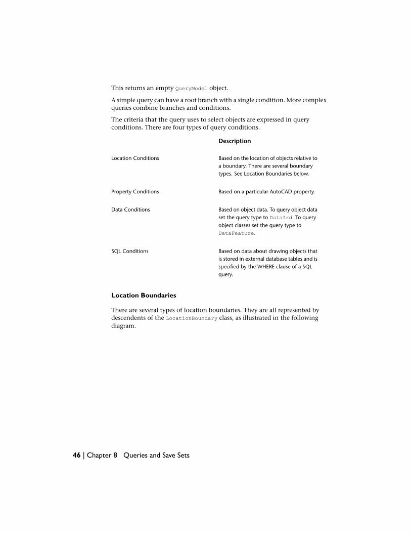
The criteria that the query uses to select objects are expressed in queryconditions. There are four types of query conditions.
Description
Based on the location of objects relative toa boundary. There are several boundarytypes. See Location Boundaries below.
Location Conditions
Based on a particular AutoCAD property.Property Conditions
Based on object data. To query object dataset the query type to DataIrd. To query
Data Conditions
object classes set the query type toDataFeature.
Based on data about drawing objects thatis stored in external database tables and is
SQL Conditions
specified by the WHERE clause of a SQLquery.
Location Boundaries
There are several types of location boundaries. They are all represented bydescendents of the LocationBoundary class, as illustrated in the followingdiagram.
46 | Chapter 8 Queries and Save Sets
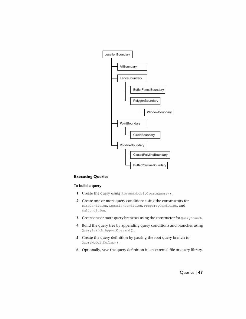
LocationBoundary
FenceBoundary
AllBoundary
PolylineBoundary
BufferFenceBoundary
PolygonBoundary
WindowBoundary
PointBoundary
CircleBoundary
ClosedPolylineBoundary
BufferPolylineBoundary
Executing Queries
To build a query
1 Create the query using ProjectModel.CreateQuery().
2 Create one or more query conditions using the constructors forDataCondition, LocationCondition, PropertyCondition, andSqlCondition.
3 Create one or more query branches using the constructor for QueryBranch.
4 Build the query tree by appending query conditions and branches usingQueryBranch.AppendOperand().
5 Create the query definition by passing the root query branch toQueryModel.Define().
6 Optionally, save the query definition in an external file or query library.
Queries | 47
To execute a query
1 You may want to set the mode, enable or disable property alteration, orcreate a report template for the query.
2 Call QueryModel.Run() to execute the query against all attached drawings.Call QueryModel.Execute() to execute the query for a particular drawingset.
The query mode determines if the objects from the attached drawings aredisplayed as a preview or cloned into the project drawing.QueryModel.Execute() returns a list of objects that have been queried in.
Query LibrariesQuery libraries provide a way to save and re-use queries. The queries can besaved internally in the project file or externally. Each project has its ownlibrary, available with ProjectModel.QueryCategories.
Libraries are divided into categories, where each category is a container forsaved queries. The saved queries are represented by QueryAttribute objects.
To add a query to the library, first add a category then add the query.
Dim queryLib As Query.QueryLibrary = activeProject.QueryCategories
Dim queryCat As Query.QueryCategory
queryCat = queryLib.AddCategory("catName")
queryCat.AddQuery("queryName", "query description", queryObj)
To save a query to an external file, call QueryModel.Save().
Save SetsEach project has a save set, which manages a list of object ids to be updatedin attached drawings.
Objects are not added to the save set automatically. It is up to the applicationto add objects using SaveSet.AddObjects().
To save objects back to an attached drawing, callAttachedDrawing.CloneBack(), AttachedDrawing.CloneBackArea(), orAttachedDrawing.CloneBackLayer().
48 | Chapter 8 Queries and Save Sets
Classification
OverviewObject classification is a way of tagging drawing objects with an object classname. This can help organize the objects in the drawing, and enforce drawingstandards.
NOTE For historical reasons, the API uses the terms feature and feature class forobject classification. These are different from FDO features and feature classes. It isimportant not to confuse the two.
Managing Feature Definition FilesFeature class definitions are stored in XML files, external to the drawing file.Before definitions from a file can be used, the file must be attached to a drawing.There can only be one attached feature definition file active at one time for agiven project.
NOTE In the UI, feature definition files are called object class definition files.
Creating Feature Definition Files
To create a feature definition file:
■ Get the classification manager object for the project usingProjectModel.ClassificationManager.
■ Create the new file usingClassificationManager.CreateFeatureDefinitionFile(). Note that the
9
49
current user must have administrative privileges in the Map session. Tocheck, test ClassificationManager.CanCurrentUserAlterSchema.
Dim classMgr As Classification.ClassificationManager
classMgr = activeProj.ClassificationManager
If (classMgr.CanCurrentUserAlterSchema) Then
classMgr.CreateFeatureDefinitionFile(filename)
Else
' Error
End If
Attaching and Detaching Feature Definition Files
To attach a feature definition file, callClassificationManager.AttachFeatureDefinitionFile().
To detach the current file, callClassificationManager.DetachCurrentFeatureDefinitionFile().
Creating Feature Class DefinitionsFeature class definitions are composed of properties that define how classifiedobjects will appear. Each feature class definition can only be used with certaintypes of drawing objects.
To create a feature class definition, start with a drawing object to use as atemplate. Get the properties of the drawing object usingClassificationManager.GetProperties(). The current values of the drawingobject become the default property values.
Determine the list of object types that the feature class definition can be usedwith. This list can be expressed as a string collection or a collection of AutoCADRXClass objects. Create the empty feature class definition usingClassificationManager.CreateFeatureClassDefinition(). Set a drawingobject type to use for creating new instances of the class usingFeatureClassDefinition.SetCreateMethod().
50 | Chapter 9 Classification
Dim classMgr As Classification.ClassificationManager
Dim newDef As Classification.FeatureClassDefinition
classMgr = activeProj.ClassificationManager
Dim trans As Transaction = Nothing
Dim obj As DBObject = Nothing
Dim cls As RXClass = Nothing
Try
trans = _
MdiActiveDocument.TransactionManager.StartTransaction()
obj = trans.GetObject(objId, OpenMode.ForRead)
cls = obj.GetRXClass()
trans.Commit()
Finally
trans.Dispose()
End Try
Dim entType As System.String = System.String.Copy(cls.Name)
Dim entTypesCol As StringCollection = New StringCollection()
entTypesCol.Add(entType)
newDef = classMgr.CreateFeatureClassDefinition( _
defName, Nothing, entTypesCol, Nothing, False)
newDef.SetCreateMethod(entType, "")
Use the FeatureClassPropertyCollection as an initial set of properties forthe feature class definition. Modify it as needed by setting range and defaultvalues for the properties in the collection. Create a newFeatureClassPropertyCollection with the updated properties. Save the featuredefinition file.
Dim classProp As Classification.FeatureClassProperty
Dim propCollection As _
Classification.FeatureClassPropertyCollection
propCollection = _
New Classification.FeatureClassPropertyCollection
classMgr.GetProperties(classPropCollection, Nothing, objId)
For Each classProp In classPropCollection
' Modify the property if necessary
newDef.AddProperty(classProp)
Next
classMgr.SaveCurrentFeatureDefinitionFile()
Creating Feature Class Definitions | 51

Classifying ObjectsTo classify a drawing object, call ClassificationManager.Classify(). Thistags the object with the name of the feature definition file and the featureclass name. If the feature definition file is detached, the classification tagremains.
A single object may be classified more than once, by using feature classes fromdifferent feature definition files. To get a list of all classifications for an object,call ClassificationManager.GetAllTags().
To unclassify an object, call ClassificationManager.Unclassify().
To get a list of all objects in a drawing that have not been classified, callClassificationManager.GetUnclassifiedEntities(). The result of this canbe used to find and classify missing objects.
52 | Chapter 9 Classification
Filters
OverviewFilters provide a simple mechanism for selecting drawing objects that meetcertain criteria. In the AutoCAD Map 3D UI, a basic filter can be used to selectdrawing objects for an export operation.
A basic filter has options for filtering based on combinations of layer names,object classification, and block names. Custom filters can filter based on othercriteria. Both types are based on the Filters.ObjectFilter class.
An ObjectFilterGroup can combine multiple filters into a single filter operation.
Objects for working with filters are in the Autodesk.Gis.Map.Filters namespace.
Basic FiltersThe FilterObjects() method for any filter takes a list of drawing objects to befiltered and returns a list of drawing objects that meet the filtering criteria.
To create a basic filter, call the constructor with a list of layer names, featureclass names, and block names. Separate multiple values with commas. An asterisk(“*”) wild card selects all objects matching the criterion.
Dim newFilter As Autodesk.Gis.Map.Filters.BasicFilter
newFilter = New Autodesk.Gis.Map.Filters.BasicFilter
("Parcels, Lots", "*", "*"))
To run a filter, call its FilterObjects() method with the output and inputObjectIdCollection objects.
10
53

Custom FiltersCustom filters can implement additional filtering capabilities. To create acustom filter, define a new class based on the ObjectFilter class. At aminimum, the custom filter must define a FilterObjects() method. It candefine any other methods needed for creating and modifying the filter.
54 | Chapter 10 Filters

Import/Export
OverviewThe AutoCAD Map 3D application maintains lists of available import and exportformats. It is not possible to modify these lists using the API. The applicationImporter and Exporter classes can import and export data using these formats.
Any import or export procedure requires the following:
■ Selecting the external file format and location
■ Mapping attribute data from the external file to object data
■ Setting any necessary driver options
■ Importing or exporting
The particular options will vary depending on the type of data being importedor exported, but the overall procedure is the same.
ImportingThe import procedure brings in objects from external files and creates newdrawing objects. Some external files have a single layer, while others have morethan one.
To start an import process, get the Importer object for the application andinitialize it with the import format name and the location of the file or files toimport. For example::
myImporter.Init("SHP", fileName)
11
55

This sets up the available layers for the import. Iterate through the layers. Foreach layer, determine if objects from the layer will be imported. SetInputLayer.ImportFromInputLayerOn.
Any attribute data attached to objects in the layers can be brought into thedrawing as object data. Each attribute in the source file corresponds to acolumn in the input layer. These columns can be mapped to fields in objectdata tables.
To map input columns, set the object data table name usingInputLayer.SetDataMapping(). Then iterate through each column, settingthe mapping for the column using Column.SetColumnDataMapping().
Different import drivers will have different options. The default options arestored in MapImport.ini. To modify the options, get the options usingImporter.DriverOptions(). This returns a name-value collection. Modify theoptions in the collection and call Importer.SetDriverOptions().
Some drivers also have an options dialog. For those drivers, callImporter.InvokeDriverOptionsDialog() to have the user set the options.
When all the mappings and driver options have been set up properly, callImporter.Import(). This returns an ImportResults object, which containsdetails of the import.
Import Events
The RecordReadyForImport event handler can be used to control which recordsare imported. The handler is fired for every record, before the import has beencompleted. To stop the import for a record, setRecordReadyForImportEventArgs.ContinueImport to false.
ExportingExporting is similar to importing, with some small differences.
To select which drawing objects should be exported, callExporter.SetSelectionSet(). To export all drawing objects, setExporter.ExportAll to true. To filter the list of objects, set theExporter.FeatureClassFilter or Exporter.LayerFilter properties.
The Exporter object does not have a property corresponding to InputLayer.The mappings for attribute data are set usingExporter.SetExportDataMappings(). This requires anExpressionTargetCollection parameter as input.
56 | Chapter 11 Import/Export

Items in an ExpressionTargetCollection object are name-value pairs, wherethe name corresponds to an object data expression and the value is theattribute name in the exported file. For details about object data expressionssee Expressions in Annotations (page 28) or the Map 3D Help.
Export Events
The RecordReadyForExport event handler is similar to RecordReadyForImport.To stop the export of a record, set RecordReadyForExport.ContinueExport tofalse.
Exporting | 57

58
Topology
OverviewA network topology contains a set of edges or links. Each link has a node ateach end. Multiple links can intersect at a single node.
A polygon topology represents an area coverage.
Topologies describe relationships between drawing objects. There are three typesof topology:
■ Node, also called point
■ Network
■ Polygon
A node topology contains a set of points.
A network topology contains a set of edges or links. Each link has a node ateach end. Multiple links can intersect at a single node.
A polygon topology represents an area coverage. The borders of polygons arerepresented by edges. The polygons in a polygon topology cannot overlap, butadjacent polygons share edges.
Each object in the topology (node, link, or polygon centroid) has an ID numberthat is unique within the topology.
NOTE The topology is related to drawing objects, but it is stored independently. Itis possible to have a topology where the nodes do not correspond to drawingobjects.
12
59
Internally, the relationship between drawing objects and topologies isimplemented using object data tables. For a topology named topol_name, thefollowing tables are used:
■ TMPCNTR_topol_name
■ TPMDESC_topol_name
■ TPMID_topol_name
■ TPMLINK_topol_name
■ TPMNODE_topol_name
TPMDESC and TPMID are not attached to any drawing objects. They are used tostore information about the topology itself. TPMDESC contains the parametersused to create the topology, such as topology type, colors, and layer names.TPMID contains a single value for the last id assigned for the topology.
TPMNODE data is attached to nodes in the topology. Each node has an ID anda resistance value.
TPMLINK data is attached to links between nodes. For network topologies thelink has values for the ID, start and end node, direction of the link, andresistance values for traversing the link in each direction. For polygontopologies the link also has values for the polygons on either side of the link.
TPMCNTR data is attached to the centroids of polygons in a polygon topology.Each centroid has values for the ID, area, perimeter, and number of links thatform the edges of the polygon.
In most cases, applications do not need to manage the object data directly.The topology API calls perform all the necessary updates. An applicationneeding to know which topologies have been defined in the drawing, however,should check the object data tables for names beginning with “TMPDESC_”.
Drawing CleanupDrawing cleanup is essential for polygon and network topologies. It ensuresthat the objects in the topology can be connected properly. For more detailsabout the various types of cleanup actions, refer to the UI documentation.
60 | Chapter 12 Topology
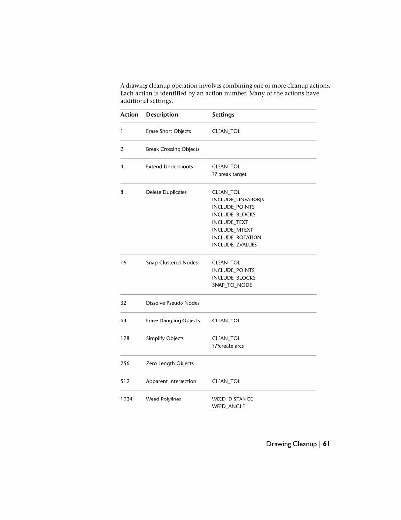
A drawing cleanup operation involves combining one or more cleanup actions.Each action is identified by an action number. Many of the actions haveadditional settings.
SettingsDescriptionAction
CLEAN_TOLErase Short Objects1
Break Crossing Objects2
CLEAN_TOL?? break target
Extend Undershoots4
CLEAN_TOLINCLUDE_LINEAROBJS
Delete Duplicates8
INCLUDE_POINTSINCLUDE_BLOCKSINCLUDE_TEXTINCLUDE_MTEXTINCLUDE_ROTATIONINCLUDE_ZVALUES
CLEAN_TOLINCLUDE_POINTS
Snap Clustered Nodes16
INCLUDE_BLOCKSSNAP_TO_NODE
Dissolve Pseudo Nodes32
CLEAN_TOLErase Dangling Objects64
CLEAN_TOL???create arcs
Simplify Objects128
Zero Length Objects256
CLEAN_TOLApparent Intersection512
WEED_DISTANCEWEED_ANGLE
Weed Polylines1024
Drawing Cleanup | 61
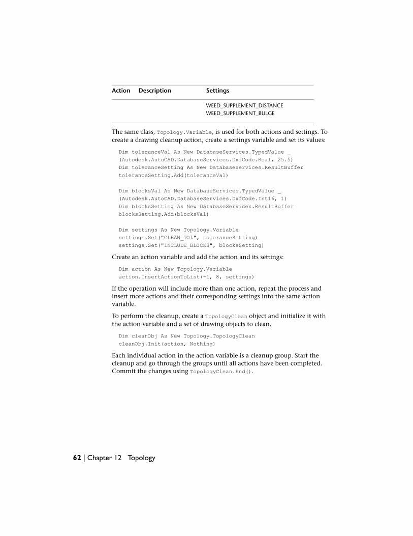
SettingsDescriptionAction
WEED_SUPPLEMENT_DISTANCEWEED_SUPPLEMENT_BULGE
The same class, Topology.Variable, is used for both actions and settings. Tocreate a drawing cleanup action, create a settings variable and set its values:
Dim toleranceVal As New DatabaseServices.TypedValue _
(Autodesk.AutoCAD.DatabaseServices.DxfCode.Real, 25.5)
Dim toleranceSetting As New DatabaseServices.ResultBuffer
toleranceSetting.Add(toleranceVal)
Dim blocksVal As New DatabaseServices.TypedValue _
(Autodesk.AutoCAD.DatabaseServices.DxfCode.Int16, 1)
Dim blocksSetting As New DatabaseServices.ResultBuffer
blocksSetting.Add(blocksVal)
Dim settings As New Topology.Variable
settings.Set("CLEAN_TOL", toleranceSetting)
settings.Set("INCLUDE_BLOCKS", blocksSetting)
Create an action variable and add the action and its settings:
Dim action As New Topology.Variable
action.InsertActionToList(-1, 8, settings)
If the operation will include more than one action, repeat the process andinsert more actions and their corresponding settings into the same actionvariable.
To perform the cleanup, create a TopologyClean object and initialize it withthe action variable and a set of drawing objects to clean.
Dim cleanObj As New Topology.TopologyClean
cleanObj.Init(action, Nothing)
Each individual action in the action variable is a cleanup group. Start thecleanup and go through the groups until all actions have been completed.Commit the changes using TopologyClean.End().
62 | Chapter 12 Topology

cleanObj.Start()
cleanObj.GroupNext()
Do While Not cleanObj.Completed
cleanObj.GroupFix()
cleanObj.GroupNext()
Loop
cleanObj.End()
For finer control over the objects being cleaned, step through the errors in agroup using TopologyClean.ErrorCur(). Fix or ignore each one individually.Set TopologyClean.ErrorPoint to change the location for the fix.
To save a profile for later use, call Variable.SaveProfile() using an actionvariable object. To reload the profile, call Variable.LoadProfile().
Creating TopologiesTo create a new topology, get the Topologies object for the project. Select thedrawing objects to include in the topology. Call Topologies.Create(). Get areference to the newly created topology using Topologies.Item(), which takesa string parameter.
Once a topology has been created, it must be opened usingTopologyModel.Open(). When the topology is no longer needed, close it withTopologyModel.Close().
Node TopologyA node topology represents a group of related points. Node topologies areoften used as part of network or polygon topologies, to represent the endpointsof the links in the topology.
TopologyModel.GetNodes() returns the collection of nodes. For each node,Node.Entity returns the associated drawing object. If the node does not havea drawing object associated with it, Node.Entity throws a MapException.
NOTE Do not update items in a NodeCollection object using methods like Add(),Insert(), and Remove(). Instead, call the appropriate methods for theTopologyModel object, like AddPointObject().
Call NodeCollection.Dispose() when the object is no longer needed.
Creating Topologies | 63
Network TopologyA network topology represents a group of related nodes and the connectionsbetween the nodes. The connections between nodes are links or edges in thetopology.
Each full edge is composed of two half edges, representing travel in oppositedirections between the nodes. Each half edge can have its own resistancevalue, which is used in certain types of network analysis.
TopologyModel.GetFullEdges() returns the collection of full edges. For eachedge, FullEdge.Entity returns the associated drawing object. If the edge doesnot have a drawing object associated with it, FullEdge.Entity throws aMapException.
FullEdge.GetHalfEdge returns a half edge, in either the forward or backwarddirection.
Polygon TopologyA polygon topology represents an area coverage, with polygons inside thearea bounded by edges. Any polygon in the topology must be entirely enclosedwithin its edges.
Each polygon must have a centroid.
TopologyModel.GetPolygons() returns the collection of polygons. For eachedge, FullEdge.Entity returns the associated drawing object. If the edge doesnot have a drawing object associated with it, FullEdge.Entity throws aMapException.
64 | Chapter 12 Topology
Display Manager
OverviewDisplay Manager provides a way to organize and style layers in AutoCAD Map3D.
NOTE The Display Manager API only manages layers that contain drawing objects.To manage layers containing FDO data use the Geospatial Platform API. See theGeospatial Platform Developer’s Guide and the Geospatial Platform API Referencefor details.
Each project has its own map manager, which is represented by aDisplayManagement.MapManager object. To get the map manager for a project,perform the following steps:
trans = activeDoc.TransactionManager.StartTransaction()
Dim managerId As ObjectId
Dim manager As MapManager = Nothing
managerId = DisplayManager.Create(activeProject).MapManagerId( _
activeProject, True)
manager = trans.GetObject(managerId, OpenMode.ForRead)
A single project can contain multiple maps. MapManager.GetEnumerator()returns an enumerator that steps through the maps in the project. The propertiesMapManager.CurrentMapId and MapManager.Current get or set the current map.
A map (DisplayManagement.Map object) is sub-classed fromDisplayManagement.Group, which represents any group of elements in DisplayManager. Maps can contain layers and more groups.
13
65
ElementsDisplay Manager elements represent the different layers in the map. Elementscan be of the following types, all subclassed from DisplayManagement.Element:
■ DisplayManagement.BaseElement
■ DisplayManagement.LayerElement
■ DisplayManagement.AttachedDwgsQueryElement
■ DisplayManagement.TopologyElement
■ DisplayManagement.TopologyQueryElement
■ DisplayManagement.FeatureElement
■ DisplayManagement.RasterElement
The following iterates through the elements in a map:
Dim iterator As IEnumerator = currentMap.NewIterator(True, True)
Dim elementType As Type = GetType(DisplayManagement.Element)
Dim groupType As Type = GetType(DisplayManagement.Group)
Do While (iterator.MoveNext())
Dim itemId As ObjectId = iterator.Current
Dim thisItem As Object = _
trans.GetObject(itemId, OpenMode.ForRead)
If (thisItem.GetType().Equals(elementType) Or _
thisItem.GetType().IsSubclassOf(elementType)) Then
Dim mapElement As Item = thisItem
' Process element (layer)
ElseIf (thisItem.GetType().Equals(groupType)) Then
Dim thisGroup As DisplayManagement.Group = thisItem
' Process group
Else
' Not a Display Manager object, probably contains FDO data
End If
Loop
The BaseElement layer represents the Map Base.
LayerElement objects display drawing objects from an AutoCAD layer.
66 | Chapter 13 Display Manager
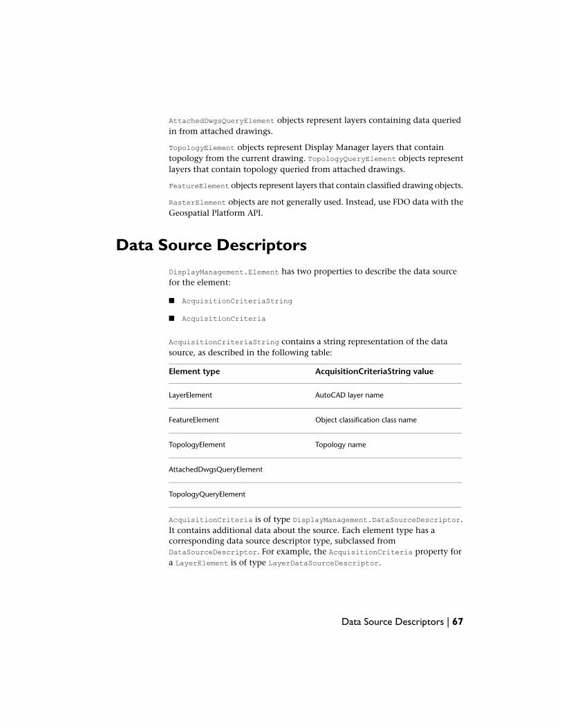
AttachedDwgsQueryElement objects represent layers containing data queriedin from attached drawings.
TopologyElement objects represent Display Manager layers that containtopology from the current drawing. TopologyQueryElement objects representlayers that contain topology queried from attached drawings.
FeatureElement objects represent layers that contain classified drawing objects.
RasterElement objects are not generally used. Instead, use FDO data with theGeospatial Platform API.
Data Source DescriptorsDisplayManagement.Element has two properties to describe the data sourcefor the element:
■ AcquisitionCriteriaString
■ AcquisitionCriteria
AcquisitionCriteriaString contains a string representation of the datasource, as described in the following table:
AcquisitionCriteriaString valueElement type
AutoCAD layer nameLayerElement
Object classification class nameFeatureElement
Topology nameTopologyElement
AttachedDwgsQueryElement
TopologyQueryElement
AcquisitionCriteria is of type DisplayManagement.DataSourceDescriptor.It contains additional data about the source. Each element type has acorresponding data source descriptor type, subclassed fromDataSourceDescriptor. For example, the AcquisitionCriteria property fora LayerElement is of type LayerDataSourceDescriptor.
Data Source Descriptors | 67
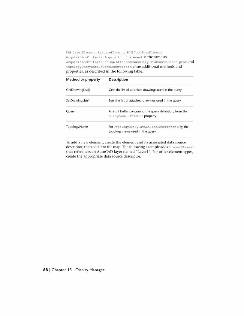
For LayerElement, FeatureElement, and TopologyElement,AcquisitionCriteria.AcquisitionStatement is the same asAcquisitionCriteriaString. AttachedDwgsQueryDataSourceDescriptor andTopologyQueryDataSourceDescriptor define additional methods andproperties, as described in the following table.
DescriptionMethod or property
Gets the list of attached drawings used in the queryGetDrawingList()
Sets the list of attached drawings used in the querySetDrawingList()
A result buffer containing the query definition, from theQueryModel.FileOut property
Query
For TopologyQueryDataSourceDescriptor only, thetopology name used in the query
TopologyName
To add a new element, create the element and its associated data sourcedescriptor, then add it to the map. The following example adds a LayerElementthat references an AutoCAD layer named “Layer1”. For other element types,create the appropriate data source descriptor.
68 | Chapter 13 Display Manager
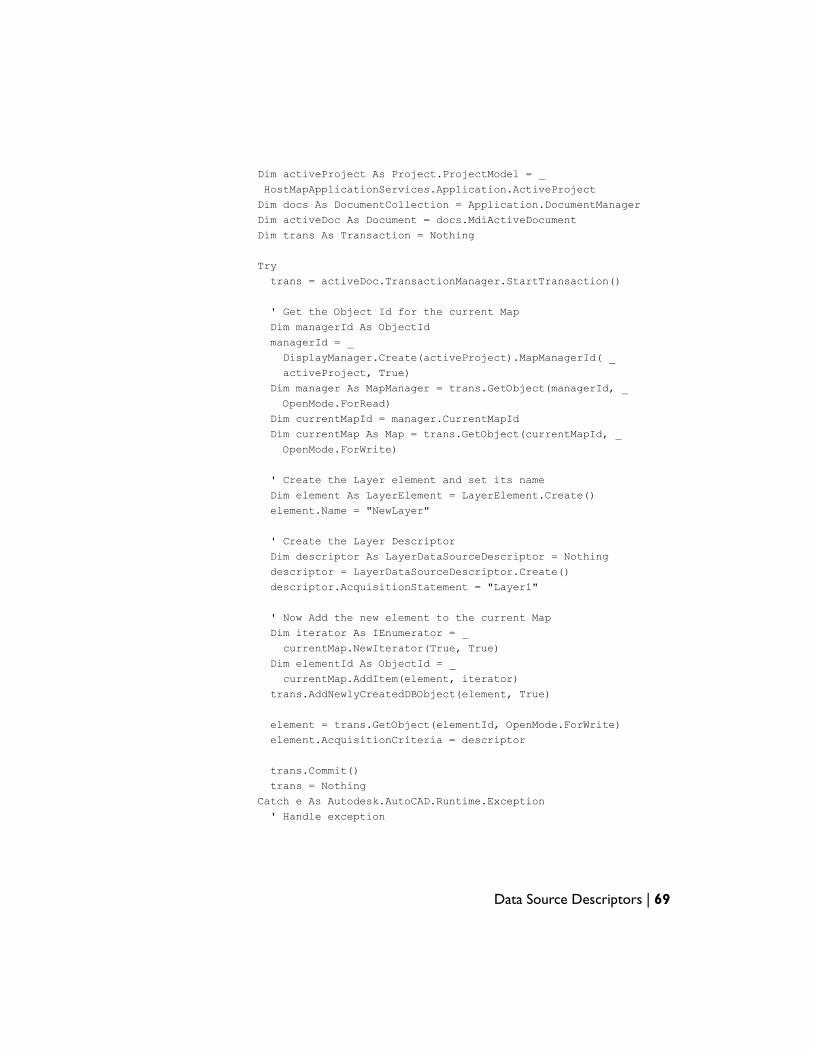
Dim activeProject As Project.ProjectModel = _
HostMapApplicationServices.Application.ActiveProject
Dim docs As DocumentCollection = Application.DocumentManager
Dim activeDoc As Document = docs.MdiActiveDocument
Dim trans As Transaction = Nothing
Try
trans = activeDoc.TransactionManager.StartTransaction()
' Get the Object Id for the current Map
Dim managerId As ObjectId
managerId = _
DisplayManager.Create(activeProject).MapManagerId( _
activeProject, True)
Dim manager As MapManager = trans.GetObject(managerId, _
OpenMode.ForRead)
Dim currentMapId = manager.CurrentMapId
Dim currentMap As Map = trans.GetObject(currentMapId, _
OpenMode.ForWrite)
' Create the Layer element and set its name
Dim element As LayerElement = LayerElement.Create()
element.Name = "NewLayer"
' Create the Layer Descriptor
Dim descriptor As LayerDataSourceDescriptor = Nothing
descriptor = LayerDataSourceDescriptor.Create()
descriptor.AcquisitionStatement = "Layer1"
' Now Add the new element to the current Map
Dim iterator As IEnumerator = _
currentMap.NewIterator(True, True)
Dim elementId As ObjectId = _
currentMap.AddItem(element, iterator)
trans.AddNewlyCreatedDBObject(element, True)
element = trans.GetObject(elementId, OpenMode.ForWrite)
element.AcquisitionCriteria = descriptor
trans.Commit()
trans = Nothing
Catch e As Autodesk.AutoCAD.Runtime.Exception
' Handle exception
Data Source Descriptors | 69
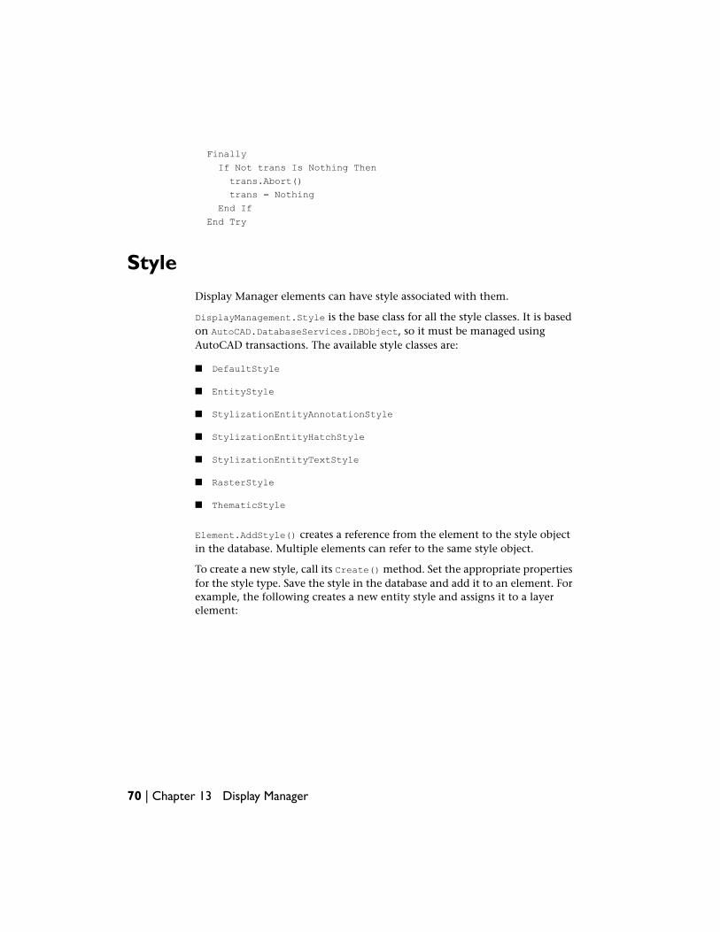
Finally
If Not trans Is Nothing Then
trans.Abort()
trans = Nothing
End If
End Try
StyleDisplay Manager elements can have style associated with them.
DisplayManagement.Style is the base class for all the style classes. It is basedon AutoCAD.DatabaseServices.DBObject, so it must be managed usingAutoCAD transactions. The available style classes are:
■ DefaultStyle
■ EntityStyle
■ StylizationEntityAnnotationStyle
■ StylizationEntityHatchStyle
■ StylizationEntityTextStyle
■ RasterStyle
■ ThematicStyle
Element.AddStyle() creates a reference from the element to the style objectin the database. Multiple elements can refer to the same style object.
To create a new style, call its Create() method. Set the appropriate propertiesfor the style type. Save the style in the database and add it to an element. Forexample, the following creates a new entity style and assigns it to a layerelement:
70 | Chapter 13 Display Manager
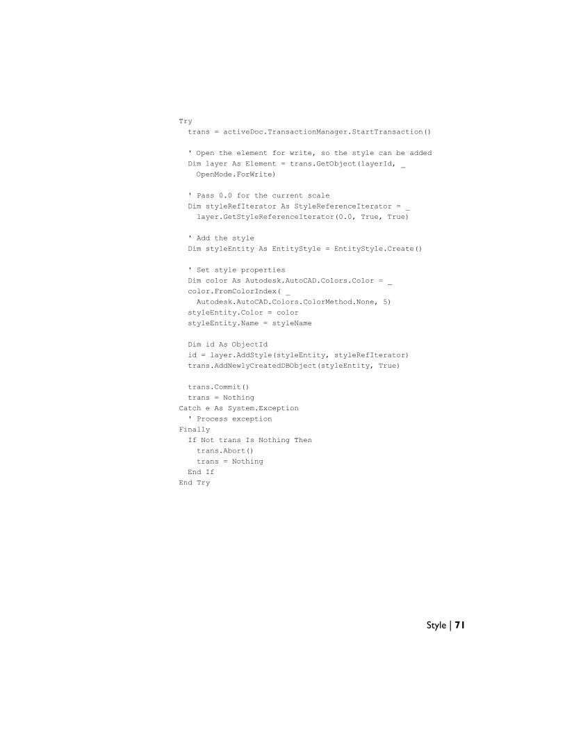
Try
trans = activeDoc.TransactionManager.StartTransaction()
' Open the element for write, so the style can be added
Dim layer As Element = trans.GetObject(layerId, _
OpenMode.ForWrite)
' Pass 0.0 for the current scale
Dim styleRefIterator As StyleReferenceIterator = _
layer.GetStyleReferenceIterator(0.0, True, True)
' Add the style
Dim styleEntity As EntityStyle = EntityStyle.Create()
' Set style properties
Dim color As Autodesk.AutoCAD.Colors.Color = _
color.FromColorIndex( _
Autodesk.AutoCAD.Colors.ColorMethod.None, 5)
styleEntity.Color = color
styleEntity.Name = styleName
Dim id As ObjectId
id = layer.AddStyle(styleEntity, styleRefIterator)
trans.AddNewlyCreatedDBObject(styleEntity, True)
trans.Commit()
trans = Nothing
Catch e As System.Exception
' Process exception
Finally
If Not trans Is Nothing Then
trans.Abort()
trans = Nothing
End If
End Try
Style | 71

72
MapBook
OverviewA Map Book is a way to divide a large map into smaller tiles, by creating aseparate layout for each tile.
Each project has its own MapBook manager. CallMapApplication.GetBookManager() to get the book manager for a database.
A Map Book requires a template file that defines the layout for each sheet inthe book.
MapBook TemplatesA Map Book template is an AutoCAD template (.dwt) file with some specialcharacteristics.
The template file must define at least one layout. The layout can containviewports for the following purposes:
■ Map view, which displays the map for the area covered by a particular sheet
■ Key view, which displays a small image of the entire map, outlining the areacovered by the map sheet
■ Map legend, which displays the map legend
The layout can also contain special blocks that show links to adjacent mapsheets. Within AutoCAD Map 3D or a DWF file, the links can be used to jumpdirectly to an adjacent sheet.
14
73
The layout can also contain a title block.
To identify objects in the template as any of the special views or blocks, callthe static function MapBook.SheetTemplate.MarkElement() with the objectid and element type. For example, to mark an object as the map view, call
MapBook.SheetTemplate.MarkElement(objId, _
MapBook.TemplateElementType.MapView)
Adjacent Map Sheets
The arrows pointing to adjacent map sheets are AutoCAD block references.Each block can have an attribute that defines the direction of the arrow andcreates a link to the adjacent sheet.
To create an arrow to an adjacent map sheet, place a block reference of thedesired shape and orientation into the map. The block reference should havean attribute named TAG. Set the text string of the attribute to an expressionthat defines the adjacent sheet. This expression is of the form:
%<\AcSm Sheet.direction >%
where direction is one of the following:
■ Top
■ Bottom
■ Right
■ Left
■ TopRight
■ TopLeft
■ BottomRight
■ BottomLeft
Creating a Map BookTo create a Map Book, define the book settings using TileGenerator andTileNameGenerator objects. Call BookManager.GenerateMapBook() to createthe new book.
74 | Chapter 14 MapBook
Index
A
AbortCSChange event 41AbortSwapId event 41acdbmgd assembly 3ACMAP_ANN_TEMPLATE_ 26AcMapDataConnectPlugins assembly 20acmgd assembly 3activeDoc 6activeProj 8AliasAdded event 35AliasDeleted event 35annotation expressions 28annotation overrides 30annotation references, inserting 29annotation templates 25–26
creating 26internal names 26
annotation text 28annotations 25, 30
updating and refreshing 30Annotations, ProjectModel class 26Annotations.CreateAnnotationTemplate()27Annotations.Item() 27Annotations.TemplateNameBlockTableRecordPrefix26AnnotationTemplate.CreateAnnotationText()28AnnotationTemplate.InsertReference() 29AnnotationTemplate.SetExpressionString()27AnnotationTemplate.UpdateReferences()30application 7assemblies, required 2AttachFeatureDefinitionFile(), in
ClassificationManager 50attaching object data 14attribute definitions 29
overriding properties 29attributes, in annotation templates 26AutoCAD database object 5AutoCAD document, and Map project 8AutoCAD RXClass objects 50AutoCAD transactions 5
Autodesk.AutoCAD.ApplicationServicesnamespace 3
Autodesk.AutoCAD.Colors namespace 3Autodesk.AutoCAD.ComponentModel
namespace 3Autodesk.AutoCAD.DatabaseServices
namespace 3Autodesk.AutoCAD.DatabaseServices.Filters
namespace 3Autodesk.AutoCAD.EditorInput
namespace 3Autodesk.AutoCAD.Geometry
namespace 3Autodesk.AutoCAD.GraphicsInterface
namespace 3Autodesk.AutoCAD.GraphicsSystem
namespace 3Autodesk.AutoCAD.LayerManager
namespace 3Autodesk.AutoCAD.PlottingServices
namespace 3Autodesk.AutoCAD.Publishing
namespace 3Autodesk.AutoCAD.Runtime
namespace 3Autodesk.AutoCAD.Windows
namespace 3Autodesk.AutoCAD.Windows.ToolPalette
namespace 3Autodesk.Gis.Map namespace 1Autodesk.Gis.Plugins assembly 20
B
BeginClose event 41BeginCSChange event 41BeginDestroy event 41BeginOpen event 41BeginQuery event 41BeginSave event 41BeginSaveBack event 41
Index | 75
BeginSwapId event 41BeginTransform event 41
C
CanCurrentUserAlterSchema property, inClassificationManager 49
CategoryAppended event 37CategoryModified event 37CategoryUnappended event 37ClassificationManager property, in
ProjectModel class 49ClassificationManager.AttachFeatureDefinitionFile()50ClassificationManager.CanCurrentUserAlterSchema
property 49ClassificationManager.CreateFeatureClassDefinition()50ClassificationManager.CreateFeatureDefinitionFile()49ClassificationManager.DetachCurrentFeatureDefinitionFile50ClassificationManager.GetAllTags() 52ClassificationManager.GetProperties() 50ClassificationManager.GetUnclassifiedEntities()52ClassificationManager.SaveCurrentFeatureDefinitionFile()51ClassificationManager.Unclassify() 52classifying objects 52CreateAnnotationTemplate(), Annotations
class 27CreateAnnotationText(),
AnnotationTemplate class 28CreateFeatureClassDefinition(), in
ClassificationManager 50CreateFeatureDefinitionFile(), in
ClassificationManager 49creating object data tables 12CurrentScaleModified event 38
D
database object id 5debugger 4deleting object data records 16DetachCurrentFeatureDefinitionFile(), in
ClassificationManager 50DismissStylizationBegin event 38DismissStylizationCancel event 38DismissStylizationEnd event 38document, and Map project 8
drawing 7drawing objects 10DrawingActivated event 40DrawingActivationCancelled event 40DrawingAttachCancelled event 40DrawingAttached event 40DrawingDeactivated event 40DrawingDetached event 40DrawingSettingsModified event 40DrawingToBeActivated event 40DrawingToBeAttached event 40
E
EndClose event 41EndCSChange event 41EndOpen event 41EndQuery event 41EndSave event 41EndSaveBack event 41EndSwapId event 42EndTransform event 42entity, and drawing object 10events, list of 35ExportRecordError event 39expressions, in annotations 28
F
feature class definitions 50creating 50
feature definition files 49–50attaching and detaching 50creating 49
FeatureClassDefinition.SetCreateMethod()50FeatureClassDefinitionCreated event 36FeatureClassDefinitionDeleted event 36FeatureClassDefinitionModified event 36FeatureClassDefinitionRenamed
event 36FeatureClassPropertyCollection 51FeatureDefinitionFileAttached event 37FeatureDefinitionFileModified event 37field definitions, for object data tables 12
76 | Index
G
GetAllTags(), inClassificationManager 52
GetProperties(), inClassificationManager 50
getting object data 14GetUnclassifiedEntities(), in
ClassificationManager 52
H
Handle 10HostMapApplicationServices.Application7
I
ImportRecordError event 39InsertReference(), in AnnotationTemplate
class 29IntOptionModified event 35, 42Item(), Annotations class 27ItemAppended event 38ItemErased event 38ItemModified event 38
M
ManagedMapApi assembly 3map 7Map 3D session 7map application 7mapApp 8MapAppended event 37MapApplication.Projects 7MapBookAppended event 39MapBookErased event 39MapBookModified event 39MapBookSetCurrent event 40MapBookTileModified event 40MapBookTileWillBeErased event 40MapBookTreeNodeModified event 40MapBookWillBeErased event 40MapGoodBye event 37MapObjectId 10
MapSetCurrentBegin event 37MapSetCurrentEnd event 37MapSetCurrentFails event 37MapUnappended event 37
N
namespaces 1
O
object class definition files 49object classification 49, 52object data 11, 14, 16
attaching to objects 14getting 14updating and deleting records 16
object data tables 11object data tables, creating 12object data tables, removing 13ObjectData.FieldDefinition 12ObjectData.Record 12ObjectId 5, 10ODTables property, in ProjectModel 11
P
project, and AutoCAD document 8ProjectBeginClose event 35ProjectCreated event 36ProjectModel 7ProjectModel properties 9ProjectModel.Annotations 26ProjectModel.ClassificationManager
property 49ProjectModel.ODTables property 11ProjectOpened event 36projects 7Projects 7properties 9
of ProjectModel 9
Q
queries 45
Index | 77
QueryAdded event 42QueryCategoryAdded event 42QueryCategoryDeleted event 42QueryCategoryRenamed event 42QueryDeleted event 42QueryModified event 42QueryRenamed event 42
R
RecordExported event 39RecordImported event 39RecordReadyForExport event 39RecordReadyForImport event 39records, in object data tables 12references, required 2refreshing annotations 30removing object data tables 13RXClass objects 50
S
SaveCurrentFeatureDefinitionFile(), inClassificationManager 51
ScaleAdded event 38ScaleErased event 38ScaleModified event 38session 7SetCreateMethod(), in
FeatureClassDefinition 50SetExpressionString(), AnnotationTemplate
class 27
StringOptionModified event 36, 42StyleAppended event 38StyleAppendedToCategory event 37StyleErased event 38StyleModified event 37StyleReferenceAppended event 38StyleReferenceErased event 38StyleReferenceModified event 38StyleUnappended event 37
T
tables, for object data 11Transaction.Open() 5transactions 5
U
Unclassify(), in ClassificationManager 52UnloadApp event 36UpdateReferences, in AnnotationTemplate
class 30UpdateStylizationBegin event 38UpdateStylizationCancel event 38UpdateStylizationEnd event 39updating annotations 30updating object data records 16
V
Visual Studio debugger 4Visual Studio, setting up 2
78 | Index