development and characterization of cerium oxide catalyst ...jmes.ump.edu.my/images/volume 10 issue...
TRANSCRIPT

Journal of Mechanical Engineering and Sciences (JMES)
ISSN (Print): 2289-4659; e-ISSN: 2231-8380
Volume 10, Issue 2, pp. 1956-1967, September 2016
© Universiti Malaysia Pahang, Malaysia
DOI: https://doi.org/10.15282/jmes.10.2.2016.2.0186
1956
Development and characterization of cerium oxide catalyst supported on ceramic
honeycomb substrate to reduce emissions of spark ignition engine
M. C. Math1* and M.S. Manjunath2
1Department of Thermal Power Engineering, Visvesvaraya Technological
University Post Graduation Center, Mysuru, Karnataka (India) *[email protected]
+919916139979 2Department of Thermal Power Engineering, Visvesvaraya Technological
University Post Graduation Center, Mysuru, Karnataka (India)
ABTRACT
This paper presents an innovative method to reduce cold start emissions of a four-stroke
three-cylinder multi point fuel injection spark ignition engine. In this work, a glow plug
is used as a heating source to maintain the activation temperature of a catalytic converter.
This method is less complex than variable vacuum insulation method. In this work,
cerium oxide (CeO2) coated on the ceramic honeycomb substrate was used as a catalyst
to lower the cost of a catalytic converter. A reduction of 34% carbon monoxide and 33%
un-burnt hydrocarbon was observed at the idling condition with CeO2 as the catalyst and
glow plug as the heating source in the catalytic converter. The results obtained from the
engine which is fitted with CeO2 coated catalytic converter show the lowest emissions at
all loads. Carbon monoxide and un-burnt hydrocarbon emissions (with catalytic
converter) have reduced 68% and 71%, respectively, in comparison with a non-catalytic
converter engine test at full load engine operation. The new catalytic converter competes
with the existing noble metal-based catalytic converter due to the use of inexpensive CeO2
as a catalyst.
Keywords: Catalytic Converter, Cerium Oxide (CeO2), Ceramic material, Glow plug.
INTRODUCTION
Catalytic converter converts more harmful gases like carbon monoxide (CO), un-burnt
hydrocarbon (HC), and oxides of nitrogen (NOx) into less harmful gases like carbon
dioxide (CO2), water vapour (H2O), and molecular nitrogen (N2). In an internal
combustion (IC) engine, the time required for the complete combustion and other
processes is much less at a higher engine speed which causes the incomplete combustion
of the fuel [1-3]. This leads to the formation of the HC, NOx (NO and NO2), and CO inside
the engine cylinder. These emissions are particularly high during the idling and
deceleration [1]. Carbon monoxide is a product of partial combustion of hydrocarbon in
fuel. It is always present when there is a lack of oxygen during the combustion and thus,
directly dependent on the applied engine air/fuel ratio [1]. There are several paths that
cause hydrocarbons in the exhaust. The most obvious is, as to the cause of CO, a lack of
oxygen when the air/fuel mixture is rich [1, 4]. NOx is formed during combustion in the
engine when oxygen reacts with nitrogen at an elevated combustion temperature [5-11].
Methods like after burner, exhaust manifold reactor, catalytic converter, and exhaust gas
Development and characterization of cerium oxide catalyst supported on ceramic honeycomb substrate to
reduce emissions of spark ignition engine
1957
recirculation are used to treat the automotive exhaust gases [5, 12]. This paper focuses on
catalytic converter technology.
In a conventional catalytic converter, materials such as platinum, rhodium, gold,
etc. are conventionally used as catalysts which are highly chemically reactive with the
exhaust gas emissions at high temperature [1]. Generally, two types of catalyst materials
are used: a reduction catalyst and an oxidation catalyst usually made of noble materials
[1, 13]. The reduction catalyst uses platinum and rhodium to reduce the NOx emissions.
When NO or NO2 molecule contacts the catalyst, the catalyst rips the nitrogen atom out
of the molecule and holds on to it, freeing the oxygen in the form of O2. The nitrogen
atoms bond with other nitrogen atoms and stuck to the catalyst, forming N2 [14]. The
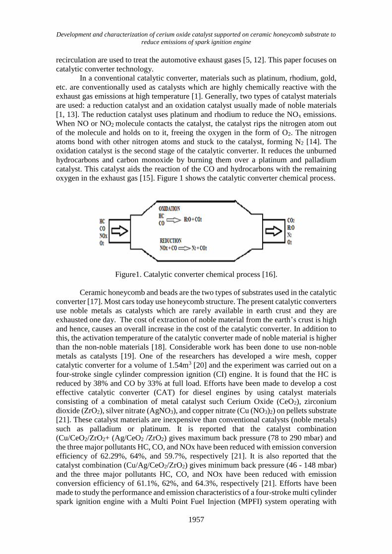
oxidation catalyst is the second stage of the catalytic converter. It reduces the unburned
hydrocarbons and carbon monoxide by burning them over a platinum and palladium
catalyst. This catalyst aids the reaction of the CO and hydrocarbons with the remaining
oxygen in the exhaust gas [15]. Figure 1 shows the catalytic converter chemical process.
Figure1. Catalytic converter chemical process [16].
Ceramic honeycomb and beads are the two types of substrates used in the catalytic
converter [17]. Most cars today use honeycomb structure. The present catalytic converters
use noble metals as catalysts which are rarely available in earth crust and they are
exhausted one day. The cost of extraction of noble material from the earth’s crust is high
and hence, causes an overall increase in the cost of the catalytic converter. In addition to
this, the activation temperature of the catalytic converter made of noble material is higher
than the non-noble materials [18]. Considerable work has been done to use non-noble
metals as catalysts [19]. One of the researchers has developed a wire mesh, copper
catalytic converter for a volume of 1.54m3 [20] and the experiment was carried out on a
four-stroke single cylinder compression ignition (CI) engine. It is found that the HC is
reduced by 38% and CO by 33% at full load. Efforts have been made to develop a cost
effective catalytic converter (CAT) for diesel engines by using catalyst materials
consisting of a combination of metal catalyst such Cerium Oxide (CeO2), zirconium
dioxide (ZrO2), silver nitrate (AgNO3), and copper nitrate (Cu (NO3)2) on pellets substrate
[21]. These catalyst materials are inexpensive than conventional catalysts (noble metals)
such as palladium or platinum. It is reported that the catalyst combination
(Cu/CeO2/ZrO2+ (Ag/CeO2 /ZrO2) gives maximum back pressure (78 to 290 mbar) and
the three major pollutants HC, CO, and NOx have been reduced with emission conversion
efficiency of 62.29%, 64%, and 59.7%, respectively [21]. It is also reported that the
catalyst combination (Cu/Ag/CeO2/ZrO2) gives minimum back pressure (46 - 148 mbar)
and the three major pollutants HC, CO, and NOx have been reduced with emission
conversion efficiency of 61.1%, 62%, and 64.3%, respectively [21]. Efforts have been
made to study the performance and emission characteristics of a four-stroke multi cylinder
spark ignition engine with a Multi Point Fuel Injection (MPFI) system operating with

Math and Manjunath / Journal of Mechanical Engineering and Sciences 10(2) 2016 1956-1967
1958
Oxyrich air energizer [22]. It is concluded that a complete combustion can be obtained
by increasing the oxygen quantity in air intake with a magnetic effect on the air. It is
reported that 10% to 25% efficiency has increased and the specific fuel consumption has
decreased (saving fuel up to 15%). The main pollutants of petrol engine (CO and HC) are
also decreased. In this method, both pollutants are reduced up to 20% to 30%. The other
pollutants of petrol engine which are CO2, O2, and N2 have increased with the increase in
load and oxygen blend quantity [22]. The effectiveness of a catalytic converter mainly
depends on operating temperature and gas feed composition. The optimum operating
temperature for catalytic converters is around 200oC to 300oC [23]. It takes a few minutes
for the engine to warm up. During this warm up period, at least 60% to 80% of toxic
emissions occur [24]. The toxic emissions that escaped unfiltered during warm up period
of the engine are called cold start emissions.
Many approaches have been proposed to reduce the cold start emissions [24-26].
The electrically quick heating method was also tried to reduce cold start emissions. This
method requires an energy input of about 2kW and 30 seconds to produce the operating
temperature. However, this method does not eliminate cold emissions completely, it only
reduces the cold start emissions level [24]. The cold start emissions can also be reduced
by fitting the catalytic converter closer to the engine. It helps the converter to reach its
operating temperature quickly. However, there is a danger of overheating of the converter
[24]. A combination of vacuum insulation and phase change material helps to eliminate
cold start emissions. Vacuum insulation prevents the transfer of radiant heat from the
exhaust to the surroundings, preserving heat between the trips. Phase change material acts
as a heat storage system and releases heat to the converter during cold start condition [24].
One of the researchers has made an attempt to improve the effectiveness of catalytic
converters via reduction of cold start emissions [25-27]. This work involves the use of
variable thermal conductance to improve the amount of heat that can reach the converter.
Low conductivity helps to retain heat between trips, but high conductivity helps to reject
excess heat while the catalytic converter is running. Vacuum insulation provides a
practical solution to these requirements [26].
The main objective of this research is to develop a cost effective non-noble metal
based catalytic converter to be used with a spark ignition engine. Hence, in this research,
an attempt has been made to use CeO2 as a catalyst material in a catalytic converter
because of its lower cost and lesser activation temperature than the noble materials. In
this research, an attempt has also been made to reduce the cold start emissions by using a
glow plug as the heating element.
MATERIALS AND METHODS
Table 1 shows the materials used for the fabrication of a catalytic converter. The outer
casing is made of stainless steel in order to provide structural strength. The honeycomb
structure is the main structural component of a catalytic converter. Ceramic honeycomb
is selected because it has a good thermal stability, high catalytic activity, high strength,
and long life. Ceramic honeycomb structures offer maximum surface areas with minimal
volume. Figure 2 shows the Ceramic Honeycomb Monolith Substrate. In this work, two
ceramic honeycomb structures are used as substrates. One is a simple ceramic honeycomb
structure and the other is a ceramic honeycomb structure coated with CeO2. Non-coated
and CeO2 (catalyst) coated ceramic cylindrical shape honeycomb substrates were
imported from the Nanjing Depurate Catalyst Co., Ltd Nanjing, China. The cylindrical
honeycomb structure has 100 mm diameter and 100 mm length. Figure 3 shows a non-

Development and characterization of cerium oxide catalyst supported on ceramic honeycomb substrate to
reduce emissions of spark ignition engine
1959
coated and CeO2 coated ceramic honeycomb substrate materials. The cylindrical
honeycomb structure has a weight to volume ratio of 0.40 (g/cm3) with a cell density of
62 (cells/cm2). The substrate has a length of 100mm and diameter of 100mm. The
substrate has a low pressure drop, chemical inertness, and structural stability at
temperature up to 500oC. In this work, cerium oxide is used as a catalyst to promote
oxygen storage, which in turn improves oxidation stability. Cerium absorbs excess
oxygen and releases it under low oxygen conditions which improve the oxidation
efficiency of HC and CO [24]. In addition to this, Cerium Oxide is inexpensive than noble
metals.
Table 1. Materials used for the fabrication of catalytic converter.
Sl. No Part Name Material Reasons
01 Outer
casing
Stainless steel Longer life, durability,
minimum expansion,
deformation
02 Monolith
Substrate
Ceramic (honeycomb shape)
mixed with precious metals and
wash coat has been formulated
for the storage of oxygen
Good thermal stability,
high catalytic activity,
high strength, long life.
03 Glow Plug Heating element
04 Cerium
Oxide
Catalyst
Figure 2. Ceramic honeycomb monolith substrate.
(a) Non coated (b) CeO2 Coated
Figure 3. Ceramic honeycomb substrate.
Table 2 describes the product test report of the ceramic honeycomb substrate (non-
coated type and catalyst coated type) which were obtained from the Nanjing Depurate

Math and Manjunath / Journal of Mechanical Engineering and Sciences 10(2) 2016 1956-1967
1960
Catalyst Co., Ltd Nanjing, China. Table 3 describes the product test report of the coating
material.
Table 2. Product test record of ceramic honeycomb substrate (non coated and coated).
Item Name Standards Test result
(Non coated)
Test result
(CeO2 coated)
SiO2 (%) 49.7±1.5 50.35 50.35
Al2O3 (%) 35.4±1.5 35.80 34.54
MgO (%) 13.5±1.5 13.10 13.9
Cell Density (cell/cm2) 62±3 62 62
Wall Thickness (mm) 0.18±0.02 0.17 0.17
Volume Weight (g/cm3) ≤0.55 0.40 0.42
Moisture Absorption (%) 25±5 25.9 26.1
Thermal Expansion Coefficient
(*10-6/0C)
≤1.8 1.27 1.30
Thermal Shock Resistance
(Air cooled)
No cracking as
putting in
temperature of
5000C than
take out to
nature cooling
for three times
No cracking as
putting in
temperature of
5000C than
take out to
nature cooling
for three times
No cracking as
putting in
temperature of
5000C than
take out to
nature cooling
for three times
Table 3. Product test record of coating material.
Item Name Standards Test result
Zr (Hf)O2 24±1 24.07
CeO2 68±1 67.94
La2O3 8±1 7.99
Na2O <0.01 <0.01
SiO2 <0.05 <0.05
Fe2O3 <0.01 <0.01
SO4-2 <0.03 <0.03
The Catalytic converter is made cylindrical because it is easy to fabricate and easy
to maintain. It requires minimum assembly time and it is rigid. Catalyst volume
(1570796.23 mm3) and space / residence time / holding time (10135.26 /hr) were
calculated using the standard formulae. The fabrication of Figure 4 shows the details of
parts of the catalytic converter. Figure 5 shows the assembled catalytic converter. The
outer casing has a diameter of 104mm and length of 350mm. The casing contains a
100mm diameter and 100mm length two honeycomb ceramic substrates which are
surrounded by a 2mm thick stainless steel mesh to hold the material tightly. The inlet
cone length of the casing is 200mm and outlet cone is 100mm. The inlet cone length is
kept larger than the outlet cone length in order to reduce the thermal stress.

Development and characterization of cerium oxide catalyst supported on ceramic honeycomb substrate to
reduce emissions of spark ignition engine
1961
(a) Catalytic Converter Casing
(b) Inlet Cone (c) Outlet Cone
(d) Cone angle (e) Cylindrical honeycomb substrate
Figure 4. Parts of catalytic converter.
Figure 5. Assembled catalytic converter.
EXPERIMENTATION DETAILS
Exhaust emission tests were carried out on a three-cylinder, the MPFI petrol engine which
is coupled with an electrical dynamometer. Table 4 shows the engine specifications. Five
gases analyzer (Indus make PEA 205 model) is connected to the tail pipe of the engine to
measure CO, CO2, HC, and O2. A probe is mounted at the exhaust pipe which supplies
exhaust gasses samples to the gas analyzer. The amount of CO, CO2, HC, and O2 present
in the exhaust can be read at the indicator panel of the exhaust gas analyzer. Engine tests
were conducted by varying the loads (0, 2, 4, 6, 8,10kg) and keeping the speed constant
(2000RPM). In this work, the speed of the engine is kept constant because the load has a
greater effect on the performance and emissions characteristics of the SI engine. By
keeping the speed constant, it is possible to study the effect of brake power, air-fuel ratio,
and torque on the performance and emissions characteristics of the SI engine. Figure 6
shows the experimental setup used in this work. In the first stage, exhaust emission test
was conducted by fitting a 100mm diameter catalyst (CeO2) coated catalytic converter to
the tail pipe of the test engine. In the second stage, exhaust emission test was conducted
by fitting a 100mm diameter non-catalyst coated (without CeO2 coating) catalytic

Math and Manjunath / Journal of Mechanical Engineering and Sciences 10(2) 2016 1956-1967
1962
converter to the tail pipe of the test engine. In the third stage, cold start exhaust emission
test was conducted by fitting a 100mm diameter catalyst coated (CeO2 coating) catalytic
converter with a glow plug in the tail pipe of the test engine. In the last stage, exhaust
emission test was conducted by fitting a 100mm diameter catalyst coated (CeO2 coating)
catalytic converter to the tail pipe of the test engine by supplying secondary air. The
results obtained in these tests have been compared to the exhaust emissions of the engine
without a catalytic converter.
Table 4. Engine specifications.
Engine MARUTI 800
BHP 12 hp
Fuel Petrol
No. Of cylinders 3 cylinders
Bore 68.5 mm
Stroke length 72 mm
Starting Self start
Working cycle Four stroke
Method of cooling Water cooled
Method of ignition Spark ignition
(a)
(b)
Figure 6. Schematic diagram and real experimental engine setup.

Development and characterization of cerium oxide catalyst supported on ceramic honeycomb substrate to
reduce emissions of spark ignition engine
1963
RESULTS AND DISCUSSION
Variation of CO Emission
Figure 7 shows the CO emission at different loads. As the load on the engine is increasing,
the CO emission is also increasing. The CO emission has increased from idling to full
load when the catalytic converter is not used. The same trend was observed for all other
test conditions. When the coated catalytic converter is fitted to the tail pipe, CO emission
was reduced by 58% at full load in comparison with CO emission when the catalytic
converter is not used because the catalyst coated on the honeycomb substrate oxidizes CO
to CO2. In addition to this, at higher engine load, conversion of CO to CO2 is more because
of higher exhaust gas temperature, which increases the catalytic activity of the catalyst
[1]. There is an appreciable reduction in CO emission in the lower load range when glow
plug is operated. The results indicate that CO emission has decreased to a value of 72%
from 75% when the glow plug is heated up in the load range of 4kg. This is because the
glow plug keeps the converter hot when exhaust gas temperatures are low. A reduction
of 50% CO emission was observed when a non-coated catalytic converter is used
compared to a non-catalytic converter engine at full load operation because the
honeycomb substrate material has SiO2, Al2O3, and MgO which act as catalysts and boost
oxidation of CO to CO2. It was also observed that CO emission has increased 19% when
the non-coated catalytic converter is used compared to the coated catalytic converter
engine at full load operation due to the use of CeO2 as a catalyst.
Figure 7. Effect of load on CO emission at different operating conditions.
Variation of HC Emission
Figure 8 shows the HC emission at different loads. It is clear from Figure 8 that HC
emission (in ppm) increases with the increase in load for all test conditions. It was
observed that HC emission has decreased 55.56% at the idling test condition and 69.23%
at full load test condition when the CeO2 coated catalytic converter is used as compared
to non-catalytic converter engine operation because the catalyst coated on the honeycomb
substrate oxidizes un-burnt hydrocarbons to water vapor and oxygen. In addition to this,
0
0.02
0.04
0.06
0.08
0.1
0.12
0 2 4 6 8 10 12
CO
em
issi
on i
n %
vol.
Load in kg
WITHOUT CATALYTIC CONVERTER
WITH CATALYTIC CONVERTER
CATALYTIC CONVERTER NON COATED
CATALYTIC CONVERTER WITH GOW PLUG

Math and Manjunath / Journal of Mechanical Engineering and Sciences 10(2) 2016 1956-1967
1964
at higher engine load, conversion of un-burnt hydrocarbons to water vapor and CO2 is
more because of higher exhaust gas temperature, which increases the catalytic activity of
the catalyst [1]. The results indicate that the HC emission has decreased to a value of
55.6% to 81.6% when the glow plug is heated up in the load range of 0kg to 4kg. A
reduction of 36.21% HC emission was observed when a non-coated catalytic converter is
used compared to a non-catalytic converter engine at full load operation because the
honeycomb substrate material has SiO2, Al2O3, and MgO which act as catalysts and boost
oxidation of CO to CO2. It was also observed that HC emission has become 2.25 times
when the non-coated catalytic converter is used compared to the coated catalytic converter
engine at full load operation due to use of CeO2 as a catalyst [1]. Thus, there is a steady
decrease in HC value with the introduction of the coated catalytic converter.
Figure 8. Effect of load on HC emission at different operating conditions.
Figure 9: Effect of load on CO2 emission at different operating conditions.
0
10
20
30
40
50
60
70
0 2 4 6 8 10 12
HC
em
issi
on i
n p
pm
Load in kg
WITHOUT CATALYTIC CONVERTER
CATALYTIC CONVERTER
CATALYTIC CONVERTER NON COATED
CATALYTIC CONVERTER WITH GLOW PLUG
0
2
4
6
8
10
12
14
0 2 4 6 8 10 12
CO
2em
issi
ons
(%vol.
)
Load in kg
WITHOUT CATALYTIC CONVERTER
WITH CATALYTIC CONVERTER
CATALYTIC CONVERTER NON COATED
CATALYTIC CONVERTER WITH GLOW PLUG

Development and characterization of cerium oxide catalyst supported on ceramic honeycomb substrate to
reduce emissions of spark ignition engine
1965
Figure 9 shows the CO2 emission at different loads. It was observed that CO2
emission increases with the increase in load for all test conditions. It was observed that
CO2 emission has decreased 5.52% at idling test condition and 1.63% at full load test
condition when the CeO2 coated catalytic converter is used compared to a non-catalytic
converter engine operation because catalyst (CeO2) oxidizes CO to CO2. The results
indicate that CO2 emission has decreased to a value of 5.39% from 23.81% when the glow
plug is heated up in the load range of 0kg to 4kg. A reduction of 2.48% CO2 emission
was observed when a non-coated catalytic converter is used compared to a non-catalytic
converter engine at full load operation because the honeycomb substrate material has
SiO2, Al2O3, and MgO which act as catalysts and boost oxidation of CO to CO2.
CONCLUSIONs
It can be concluded that the CO, HC, and CO2 emissions can be reduced by using CeO2
coated catalytic converter at all engine load operations. It can also be concluded that cold
start emissions can be controlled using a glow plug along with the CeO2 coated catalytic
converter. The catalytic converter made of the non-noble (CeO2) material has significant
advantages such as inexpensive than the catalytic converter based on the noble material
and a lower operating temperature than the noble metal and also the easy availability of
the non-noble material. The non-noble material catalytic converter is the best option for
reducing pollution when noble materials are not available.
ACKNOWLEDGEMENTS
The authors gratefully thank Nanjing Depurate Catalyst Co., Ltd, Nanjing, China for
supplying both non-coated and CeO2 (catalyst) coated type ceramic honeycomb
substrates. The author would like to be obliged to Tech-Ed Equipment Company Pvt. Ltd,
Bangalore (India) for providing laboratory facilities to carry the exhaust gas analysis. The
authors also acknowledge the support rendered by the staff of Department of Thermal
Power Engineering, Visvesvaraya Technological University, Post Graduation Center,
Mysore.
.
REFERENCES
[1] Heywood JB. Internal combustion engine fundamentals: Mcgraw-hill New York;
1988.
[2] Hasan MM, Rahman MM. Homogeneous charge compression ignition
combustion: Advantages over compression ignition combustion, challenges and
solutions. Renewable and Sustainable Energy Reviews. 2016;57:282-91.
[3] Yasin MHM, Mamat R, Aziz A, Yusop AF, Ali MH. Investigation on combustion
parameters of palm biodiesel operating with a diesel engine. Journal of
Mechanical Engineering and Sciences. 2015;9:1714-26.
[4] Mathur M, Sharma R. Internal combustion engines: Dhanpat Rai Publ.; 2005.
[5] Ganesan V. Internal combustion engines: McGraw Hill Education (India) Pvt Ltd;
2012.
[6] Sher E. Handbook of air pollution from internal combustion engines: pollutant
formation and control: Academic Press; 1998.

Math and Manjunath / Journal of Mechanical Engineering and Sciences 10(2) 2016 1956-1967
1966
[7] Muharam Y, Mahendra M, Gayatri D, Kartohardjono S. Simulation of ignition
delay time of compressed natural gas combustion. International Journal of
Automotive and Mechanical Engineering. 2015;12:3125-40.
[8] Noor MM, Wandel AP, Yusaf T. The simulation of biogas combustion in a mild
burner. Journal of Mechanical Engineering and Sciences. 2014;6:995-1013.
[9] Noor MM, Wandel AP, Yusaf T. Effect of air-fuel ratio on temperature
distribution and pollutants for biogas MILD combustion. International Journal of
Automotive and Mechanical Engineering. 2014;10:1980-92.
[10] Kumaran P, Gopinathan M, Kantharrajan S. Combustion Characteristics of
Improved Biodiesel in Diffusion Burner. International Journal of Automotive and
Mechanical Engineering. 2014;10:2112-21.
[11] Hamada KI, Rahman MM, Abdullah MA, Bakar RA, A. Aziz AR. Effect of
mixture strength and injection timing on combustion characteristics of a direct
injection hydrogen-fueled engine. International Journal of Hydrogen Energy.
2013;38:3793-801.
[12] Jaichandar S, Annamalai K. Jatropha oil methyl ester as diesel engine fuel - an
experimental investigation. International Journal of Automotive and Mechanical
Engineering. 2016;13:3248-61.
[13] Pundir B. Engine emissions: pollutant formation and advances in control
technology: Alpha Science International, Limited; 2007.
[14] Kisku G. Nature and Type of Pollution from Automobiles and Strategies for its
Control. Industrial Toxicology Research Centre, Environmental Monitoring
Division, Lucknow. 2013:1-16.
[15] Ye S. Oxidation Catalyst Studies on a Diesel Engine: University of Bath; 2010.
[16] Crypton. Understanding CAT - Catalytic Converters. 2012.
[17] Kašpar J, Fornasiero P, Hickey N. Automotive catalytic converters: current status
and some perspectives. Catalysis Today. 2003;77:419-49.
[18] Wei J. Catalysis for motor vehicle emissions. Advances in Catalysis. 1975;24:57-
129.
[19] Shinjoh H. Rare earth metals for automotive exhaust catalysts. Journal of Alloys
and Compounds. 2006;408:1061-4.
[20] Amin C, Rathod PP, Student P. Catalytic converter based on non-noble material.
International Journal of Advanced Engineering Research and Studies; 2012.
[21] Walke P, Deshpande N, Mahalle A. Emission characteristics of a compression
ignition engine using different catalyst. Proceedings of the World Congress on
Engineering: Citeseer; 2008.
[22] Gaikward D, Dange H. Experimental investigation of four stroke SI engine using
oxyrich air energizer for improving its performance. International Journal of
Technology Enhancements and Emerging Engineering Research,. 2014;2:104-9.
[23] Gaines L, Rask E, Keller G. Which Is Greener: Idle, or Stop and Restart?
Comparing Fuel Use and Emissions for Short Passenger-Car Stops.
Transportation Research Board of the National Academies. 2012.
[24] Burch SD, Keyser MA, Potter TF, Benson DK. Thermal analysis and testing of a
vacuum insulated catalytic converter. SAE Technical Paper; 1994.
[25] Veeraragavan V. Fabrication and testing of a catalytic convertor. International
Journal of Application or Innovation in Engineering & Management. 2013;2:350-
4.
[26] Karuppusamy P, Senthil DR. Design, Analysis Of Flowcharacteristics Of
Catalytic Converterandeffects Of Backpressure On Engine Performance.

Development and characterization of cerium oxide catalyst supported on ceramic honeycomb substrate to
reduce emissions of spark ignition engine
1967
International journal of Research in Engineering and Advanced technology.
2013;1.
[27] Bhaskar K, Nagarajan G, Sampath S. Experimental investigation on cold start
emissions using electrically heated catalyst in a spark ignition engine.
International Journal of Automotive and Mechanical Engineering. 2010;2:105-18.
NOMENCLATURES
CO – Carbon Monoxide
CC – Catalytic Converter
HC – Hydrocarbon
SiO2 – Silica
MgO – Magnesia
Al2O3 – Aluminum oxide
La2O3 – Lanthanum oxide
Na2O – Sodium oxide
Fe2O3 – Ferric oxide
SO4-2 – Sulfate