development of a cost-effective system to monitor wind
TRANSCRIPT

Arnold Schwarzenegger Governor
DEVELOPMENT OF A COST-EFFECTIVE SYSTEM TO MONITOR WIND TURBINES
FOR BIRD AND BAT COLLISIONS PHASE I:
SENSOR SYSTEM FEASIBILITY STUDY
Prepared For: California Energy Commission Public Interest Energy Research Program
PIER
FINA
L PR
OJEC
T RE
PORT
Prepared By: EDM International, Inc.
March 2007 CEC-500-2007-004


Prepared By: EDM International, Inc. A. Pandey, J. Hermence, and R. Harness Fort Collins, Colorado Commission Contract No. 500-01-032
Prepared For: Public Interest Energy Research (PIER) Program California Energy Commission
Linda Spiegel Contract Manager
Kelly Birkinshaw Program Area Lead Energy-Related Environmental Research
Laurie ten Hope Office Manager Energy Systems Research Office
Martha Krebs Deputy Director
ENERGY RESEARCH & DEVELOPMENT DIVISION
B.B. Blevins Executive Director
DISCLAIMER This report was prepared as the result of work sponsored by the California Energy Commission. It does not necessarily represent the views of the Energy Commission, its employees or the State of California. The Energy Commission, the State of California, its employees, contractors and subcontractors make no warrant, express or implied, and assume no legal liability for the information in this report; nor does any party represent that the uses of this information will not infringe upon privately owned rights. This report has not been approved or disapproved by the California Energy Commission nor has the California Energy Commission passed upon the accuracy or adequacy of the information in this report.

Acknowledgments
This report was reviewed by Karin Sinclair (National Renewable Energy Lab), Mike Azeka (SeaWest), Jim Lindsay (Florida Power and Light), Dora yen (California Energy Commission), Peter Spaulding (California Energy Commission), and Linda Spiegel (California Energy Commission).
Please cite this report as follows:
Pandey, A., et al. 2006. Development of a Cost-Effective System to Monitor Wind Turbines for Bird and Bat Collisions—Phase I: Sensor System Feasibility Study. California Energy Commission, PIER Energy-Related Environmental Research. CEC-500-2007-004.
i

ii

Preface
The Public Interest Energy Research (PIER) Program supports public interest energy research and development that will help improve the quality of life in California by bringing environmentally safe, affordable, and reliable energy services and products to the marketplace.
The PIER Program, managed by the California Energy Commission (Energy Commission), conducts public interest research, development, and demonstration (RD&D) projects to benefit California.
The PIER Program strives to conduct the most promising public interest energy research by partnering with RD&D entities, including individuals, businesses, utilities, and public or private research institutions.
PIER funding efforts are focused on the following RD&D program areas:
Buildings End‐Use Energy Efficiency •
•
•
•
•
•
•
•
Energy Innovations Small Grants
Energy‐Related Environmental Research
Energy Systems Integration
Environmentally Preferred Advanced Generation
Industrial/Agricultural/Water End‐Use Energy Efficiency
Renewable Energy Technologies
Transportation Development of a Cost-Effective System to Monitor Wind Turbines for Bird and Bat Collisions— Phase I: Sensor System Feasibility Study is the final report for the Development of a Cost-Effective System to Monitor Wind Turbines for Bird and Bat Collisions project (contract number 500-01-032) conducted by EDM International, Inc. The information from this project contributes to PIER’s Energy-Related Environmental Research Program.
For more information on the PIER Program, please visit the Energy Commission’s website www.energy.ca.gov/pier or contract the Energy Commission at (916) 654-5164.
iii

iv

Table of Contents Preface.........................................................................................................................................................iii Abstract......................................................................................................................................................vii Executive Summary................................................................................................................................... 1 1.0 Introduction...................................................................................................................................... 3
1.1. Background and Overview................................................................................................... 3 1.2. Project Objectives ................................................................................................................... 3
2.0 Avian Collisions with Wind Turbines .......................................................................................... 4 3.0 Wind Turbine Configurations ....................................................................................................... 5 4.0 Potential Collision Monitoring Sensors........................................................................................ 6
4.1. Contact Sensors ...................................................................................................................... 6 4.1.1. Accelerometers .................................................................................................................. 6 4.1.2. Fiber-optic sensors ............................................................................................................ 8
4.2. Non-Contact Sensors ............................................................................................................. 8 4.2.1. Radar and infrared: not suitable for collision detection .............................................. 8 4.2.2. Acoustic emission sensors (microphones)..................................................................... 9
5.0 Evaluation of Potential Collision Monitoring Sensors ............................................................. 10 5.1. Installation—Existing/New Wind Turbines.................................................................... 10 5.2. Signal Processing.................................................................................................................. 11 5.3. Cost......................................................................................................................................... 12 5.4. Ranking of Potential Collision Monitoring Sensors ........................................................ 12
6.0 Acoustic Emission Sensor Laboratory Trial............................................................................... 14 7.0 Conclusions and Recommendations........................................................................................... 17
7.1. Conclusions........................................................................................................................... 17 7.2. Recommendations................................................................................................................ 17
7.2.1. Phase II: Proof-of-concept testing ................................................................................. 17 7.2.2. Phase III: Prototype fabrication, field evaluation, and further development......... 18
7.3. Benefits to California ........................................................................................................... 18 8.0 References ....................................................................................................................................... 19
v

List of Figures
Figure 1. Horizontal-axis wind turbine................................................................................................... 5
Figure 2. Schematic of a typical wind turbine........................................................................................ 5
Figure 3. Bird Strike Indicator (BSI) sensor installed on a power line................................................ 7
Figure 4. Accelerometer used in the BSI sensors ................................................................................. 11
Figure 5. Pictures of microphone components selected for trial ....................................................... 14
Figure 6. Setup for collecting data from microphone sensor............................................................. 16
List of Tables
Table 1. Specifications for different pre-polarized microphones available from PCB ................... 15
Table 2. Specifications for preamplifiers............................................................................................... 15
vi

Abstract
Bird and bat collisions with wind turbines are of increasing concern to utilities, regulatory agencies, and environmental organizations. Kills have been documented at several wind farms; however, the magnitude of the problem industry-wide is unknown. This report presents the results of a feasibility study for a sensor aimed at developing an automated tool to monitor collisions with wind turbines.
Accelerometers and fiber-optic sensors were identified as possible contact sensor options. Acoustic emission sensors (microphones) were identified as a non-contact option that need not be installed directly on the rotor blades. The three sensor technologies were evaluated on the basis of installation requirements, signal processing needs, and system cost.
Microphones were deemed the most viable sensor system overall. Accelerometers were ranked second because they need to be installed on the rotor blades and thus require associated hardware mounted on the rotor shaft. Fiber-optic sensors were deemed the least feasible, as they have similar installation requirements as the accelerometers and higher equipment costs; moreover, the fiber-optic systems are bulky and would require custom hardware to reduce their size for practical installation on the rotor shaft.
Keywords: Wind turbine, bird collision, bat collision, collision monitor, collision sensors, bird sensors, Bird Strike Indicator
vii

viii
Executive Summary Introduction
Bird and bat collisions with wind turbines are of increasing concern to utilities, regulatory agencies, and environmental organizations. Kills have been documented at several wind farms; however, the magnitude of the problem throughout the industry is unknown, in large part because there is currently no cost-effective means for monitoring collisions with turbine blades on a regular and widespread basis. An automated collision monitor is needed to provide the basis for meaningful study. Such a monitor would collect the information necessary to better define the collision problem and help assess the effectiveness of potential solutions.
Purpose
This study is the initial phase of a three-phase effort to develop an automated bird/bat collision monitor that is reliable, affordable, and does not significantly impair wind turbine performance.
Project Objectives
This initial phase investigated the feasibility of developing sensor systems for two distinct wind turbine collision-monitoring applications:
Technologies suitable for retrofitting common configurations of existing wind turbines. •
•
•
•
Technologies suitable for incorporation in new turbines. The goal was to identify relatively low-cost sensor systems that can provide long-term, reliable collision monitoring without significant impact on turbine operation. Both contact and non-contact sensor systems were investigated.
Project Outcomes
A literature search identified three candidate sensor technologies for monitoring bird and bat collisions with wind turbines. Accelerometers and fiber-optic sensors were identified as possible contact sensors, i.e., sensors that must be installed directly on the wind turbine rotor blades. Acoustic sensors (microphones) were identified as a potential non-contact sensor that would not need to be installed on the rotor blades. The three sensor technologies were evaluated on the basis of installation requirements, signal processing needs, and system cost. Installation requirements for both existing and new wind turbines were considered.
Conclusions
The findings of the sensor system feasibility study are as follows:
The acoustic emission sensor (microphone) is expected to be the most viable sensor system overall due to its ease of installation and low-cost, off-the-shelf components. Accelerometers are ranked second, primarily because they must be installed on the rotor blades and require associated hardware to be mounted on the rotating rotor shaft. Only a small, lightweight accelerometer would need to be installed on each of the blades and could be installed on the inside of the hollow blades. The accelerometer-based Bird Strike Indicator (BSI) sensor could be modified for this application, thereby minimizing development requirements.
1

Fiber-optic sensors are the least feasible, since they have the same on-blade installation requirements as the accelerometers but use more expensive equipment. These sensors are relatively new and their associated hardware is still somewhat bulky and expensive. Custom hardware would need to be developed to make a fiber-optic system practical for installation on the rotor shaft.
•
•
•
•
•
•
•
•
•
Turbine operating and environmental noise (mechanical sounds, wind, rain, thunder)will be a key factor determining the success of the acoustic emission sensor for collisiondetection. Rotor blade vibrations will also affect the ability of accelerometers to detectcollisions. Field measurements are needed to further evaluate the feasibility of using acoustic sensors versus accelerometers for detecting bird/bat collisions with wind turbines.
Recommendations
Further development of a sensor system to monitor wind turbines for bird and bat collisions should be carried out in two phases. Phase II of this project is envisioned as a proof-of-concept phase to collect data on a test turbine at the National Renewable Energy Laboratory in Golden, Colorado. Phase II will comprise the following steps:
Assemble off-the-shelf components and develop an acoustic emission sensor system. Adapt the BSI for use as a possible accelerometer-based sensor system. Test the systems on wind turbines with simulated strikes. Determine the sensitivity of the acoustic sensor system versus the accelerometer system. Make recommendations for prototype system development.
Phase III of the project should design and assemble a prototype sensor system for field testing and evaluation on different types of operational wind turbines. A commercialization plan should also be developed as part of Phase III.
Benefits to California
This project offers numerous benefits and meets the following PIER program objectives:
Developing cost-effective approaches to evaluating and resolving environmental effects of energy production. An automated sensor system will enable cost-effective study of bird/bat interactions with wind turbines. Such a system will greatly advance scientific understanding of the bird/bat collision problem and allow researchers to assess the efficacy of available tools and methodologies to mitigate the problem. Providing environmentally sound energy. Identifying effective methods to mitigate wind turbine impacts on wildlife will promote deployment of wind power, a clean energy source.
2
1.0 Introduction
1.1. Background and Overview The relatively recent emphasis on electric utilities offering renewable energy as part of their generation portfolio, coupled with significant advances in wind energy technology made by organizations such as the U.S. Department of Energy (DOE) over the last 30 years, has catalyzed a resurgence in interest in wind energy, and in particular the deployment of large-capacity wind turbines. In 2003 alone, U.S. wind generating capacity increased by more than 30%, and the American Wind Energy Association (AWEA) forecasts more than a 30% increase in U.S. wind generation capacity in 2005 (AWEA 2005a, 2005b). The AWEA projects that wind energy can provide at least 6% of the nation’s electricity by 2020 (AWEA 2005b). But although wind turbines provide a significant source of renewable energy, their use often includes unknown impacts to birds and bats; some of which are legally protected species.
Bird and bat collisions with wind turbines are of increasing concern to utilities, regulatory agencies, and environmental organizations. Kills have been documented at several wind farms; however, the magnitude of the problem industry-wide is unknown—in part because there is no cost-effective means for monitoring collisions with turbine blades on a widespread basis. Automated monitoring technology is needed to provide the basis for meaningful study by enabling collection of information to better define the problem and to aid in assessing the effectiveness of potential solutions.
This project was initiated to investigate promising sensor technologies to enable cost-effective monitoring for collisions. This project is envisioned to be the first phase of a multi-phase effort culminating in the development of a viable, cost-effective system for monitoring turbine collisions. In addition, there is a reasonable possibility that the developed technology will offer an ancillary benefit of being useful for continuous on-line monitoring of turbine blade health. This secondary application could be a valuable benefit in older wind farms, as the wind energy industry has experienced some blade failures that could have been detected by sensor monitoring.
1.2. Project Objectives The primary objective of this project was to investigate the feasibility of developing sensor systems for two distinct wind turbine collision-monitoring applications:
Technologies suitable for retrofit of common configurations of existing wind turbines. •
• Technologies suitable for incorporation in new turbines. The goal was to identify relatively low-cost sensor systems that could provide reliable long-term monitoring without significant impact on the turbine operation. The plan was to investigate both contact and non-contact sensor systems.
As an outcome of the project, promising sensor systems were to be described with the goal of developing a prioritized list of viable technologies and recommendations for prototype development and testing during a subsequent project (Phase II).
3

2.0 Avian Collisions with Wind Turbines Two types of local impacts to birds have been demonstrated at existing wind plants: (1) direct mortality from collisions, and (2) indirect impacts from avoidance, habitat disruption, and displacement. Direct impacts to bats have also been documented at some wind plants (NWCC 2004).
A large number of surveys of avian fatalities have been conducted at wind plants in U.S. and Europe (Howell et al. 1991, Johnson et al. 2000, Benner et al. 1993, and Musters 1991, Smallwood and Thelander 2004, Orloff and Flannery 1992, 1996). Synthesizing the results of these studies has been problematic due to a number of factors (Sterner 2002). Field survey methods vary, and the bias in the detection and removal of bird carcasses is sometimes known and often unknown. There has been an emphasis on larger birds such as raptors, despite the knowledge that smaller birds are also affected. Very few studies have been peer-reviewed or published in scientific journals. The design and layout of turbines, as well as the climate, topography, and avian species present vary greatly among the wind plants studied. Finally, the relatively low numbers of observed fatalities in the studies result in inadequate sample sizes. Despite these difficulties, consideration of the available data can yield insight into the impacts of wind turbines on avian species.
By the end of 2003, there were about 4,700 turbines (producing 4,300 megawatts) installed in the U.S. outside of California, and studies showed an average avian fatality rate of 2.3 birds and 3.4 bats per turbine per year and 3.1 birds and 4.6 bats per megawatt per year (NWCC 2004). These fatality rates are based on 12 studies and have been adjusted for searcher efficiency and scavenging bias.
In California by the end of 2003, there were about 7,300 turbines (producing 2,100 megawatts) installed (NWCC 2004). Most of these turbines are older and smaller than those elsewhere in the U.S. Methods used in early California studies of avian fatalities at wind power projects led to high uncertainty or did not account for searcher efficiency and scavenging bias. Two California studies which have been adjusted for searcher efficiency and scavenger bias report estimates of 2.3 birds per turbine at San Gorgonio and 8.1 birds per megawatt per year at Altamont Pass (NWCC 2004). A report for Tehachapi Pass, California, estimated 0.047 raptor fatalities per turbine per year and 0.25 raptor fatalities per year, unadjusted for searcher efficiency and scavenger bias and with a high level of uncertainty resulting from methods used (Anderson et al. 2004). A recent report for San Gorgonio, California, estimated 0.006 raptor fatalities per turbine per year and 0.03 raptor fatalities per megawatt per year, unadjusted for searcher efficiency and scavenger bias and with a high level of uncertainty resulting from methods used (Anderson et al. 2005). One recent study at the High Winds project in California reported avian fatality rates of 2.45 birds per turbine per year and 3.63 bats per turbine per year, adjusted for searcher efficiency and scavenger bias (Kerlinger et al. 2006).
4

3.0 Wind Turbine Configurations Horizontal-axis wind turbines typically have two or three blades. The three-bladed wind turbines are typically operated “upwind,” with the blades upwind of the tower (Figure 1).
Horizontal-axis wind turbines can be broken down into four basic subsystems: rotor, drive train, tower, generator, and electrical controls. Figure 2 shows a schematic of a typical wind turbine.
Figure 1. Horizontal-axis wind turbine
Figure 2. Schematic of a typical wind turbine
5

4.0 Potential Collision Monitoring Sensors The goal for this project was to identify the most feasible sensors and technologies for detecting bird and bat collisions with wind turbines. Collision can either occur at the turbine tower or the rotor blade. With increasing lengths of rotor blades in wind turbines and because of the area that the rotor blades cover, collision with the rotor blades is likely the biggest concern. However, it is much easier to detect collision with the stationary tower than with the rotating blades.
In order to detect collision with the rotor blades, either (1) sensors must be directly installed on the blades (contact sensors) or (2) certain characteristics of the collision must be monitored remotely (non-contact sensors). A variety of sensors can be installed on the blades and used to monitor parameters such as vibration or strain resulting from a collision; accelerometers, fiber-optic sensors, and strain gages are examples of possible contact sensors. Acoustic sensors, which would listen for the sound of a bird or bat impact, are a non-contact option for remotely monitoring collisions. Each of these sensor options is further described in the following pages.
Besides the sensor itself, both contact and non-contact sensor systems comprise several components for signal conditioning and data acquisition. A typical sensor system will consist of the following components:
Sensor(s) •
•
•
•
•
•
Signal conditioner/amplifier Analog filter Analog-to-digital converter Data logger/computer Modem or other communication device for remote data access
The signal conditioner/amplifier is unique for each sensor type. However, the rest of the system could be identical for different sensors, and most components are available “off the shelf.” Custom-designed hardware might be needed to minimize the size of the equipment, especially for contact sensors that would be installed on the rotor shafts.
4.1. Contact Sensors Contact sensors are installed directly on the turbine blades to monitor localized responses of the rotor blade to collision. Accelerometers and fiber-optic sensors were the two options identified as potential contact sensors for collision monitoring. Since the blades are rotating, wireless data communication from the sensors is needed.
4.1.1. Accelerometers Accelerometers measure the vibration response of structures and have been widely used in a variety of industries for condition monitoring. For example, accelerometers are used in the automotive industry as collision detection sensors for deploying airbags.
Accelerometers come in a variety of sizes, weights, and frequency ranges. Accelerometers can be glued, magnetically mounted, or attached to a structure using a threaded screw. The attachment method is selected based on the frequency range of interest. Accelerometers require
6

either a constant-voltage power supply or a constant-current power supply. These power supplies are often called signal conditioners and can also incorporate an amplifier to magnify the small current or voltage signal output from the sensors. An analog-to-digital converter is used to digitize the analog signal prior to logging it, using a computer, micro-controller, or a datalogger. Analog filters can be used prior to digitizing to remove certain unwanted low or high frequencies.
Accelerometers have been widely used for a long time and hence are very advanced and have been miniaturized to not only reduce their size but also power consumption. Recently, EDM International, Inc., has developed a Bird Strike Indicator (BSI) sensor that uses accelerometers to detect avian collision with power lines and communication tower guy wires (CEC PIER Report 2003). The BSI sensor, shown in Figure 33, uses very-low-power-consuming accelerometers and has a custom-designed circuit board that combines the signal conditioner, amplifier, and analog filter, along with an analog-to-digital converter. It uses wireless communication to communicate strike data from the sensor to a base station that could be a computer or some other data logger. Data from the computer/data logger can be accessed remotely via a variety of communication options. The BSI sensor electronics could likely be adapted to the wind turbine application.
Figure 3. Bird Strike Indicator (BSI) sensor installed on a power line
7
4.1.2. Fiber-optic sensors Fiber-optic sensors are gaining wide acceptance for measuring strain, temperature, and load and have also been recently investigated for condition monitoring of wind turbine blades (Rademakers et al. 2004). The primary advantage of fiber-optic sensors over conventional strain gages is that they are not sensitive to electromagnetic fields and lightning.
A fiber-optic sensor system consists of a fiber-optic cable connected to a remote sensor, i.e., an amplifier. The cable is the mechanical component that transports the light into and out of areas that are either too space constrained or too hostile back to the sensor. The sensor emits, receives, and converts the light energy into an electrical signal.
Fiber-optic sensor systems are a derivative of photoelectric sensing technology. There are two sensing modes available for fiber optics—through-beam mode and bifurcated mode.
Fiber-optic through-beam mode uses an emitter to guide light energy to a sensing location and a receiver to guide light energy from the sensing location back to the remote sensor. The emitter and detector are positioned opposite each other. Sensing is achieved when the light beam that extends from the emitter to the receiver fiber-optic cable is interrupted.
A bifurcated fiber-optic assembly uses a bifurcated cable to connect the emitter and the receiver. When an object is in front of the sensing tip of the bifurcated cable, light from the emitter cable reflects off the object and back into the receiver of the remote sensor via the receiver cable, and detection is achieved.
Fiber-optic sensor modules can be glued on the turbine blade like conventional strain gages. The sensor modules are connected to a remote signal conditioning module using fiber-optic cables. This remote module could also integrate an analog-to-digital converter to digitize the signals before logging them for further processing. The remote module needs to be mounted on the rotor of the wind turbine and wireless communication must be used to retrieve the data.
4.2. Non-Contact Sensors Non-contact sensors for detecting wind turbine collisions remotely detect characteristics of collisions with the rotor blades. A variety of sensor technologies can detect bird activity in the vicinity of the wind turbine but can not automatically detect collision without a lot of processing.
4.2.1. Radar and infrared: not suitable for collision detection Ground-based radar has been used to monitor avian activity near a wind farm (Gauthreaux 1984). A mobile research laboratory developed for the Electric Power Research Institute (EPRI) uses two marine radars to monitor bird movement near transmission lines day and night. A fixed-beam radar directed vertically is used to measure the altitude of the migrating birds, and a surveillance-type radar is used to examine the geographical patterns of movements. Another application for radar is to monitor patterns of bird movements in the vicinity of airports that have potential bird strike problems (Spruyt and vanDorp 1996).
Machine vision or thermal infrared imaging can also be used to detect or track bird or bat movements (Melton et al. 2005). A digital image processing technique based on differencing sequential frames to remove stationary clutter can be used to track moving objects. Video
8
cameras are used for surveillance and monitoring (Waldl and Pahlke 2001) and can offer an excellent visual record of collision if combined with an automated sensor that detects the collision and starts recording the video.
Both radar and machine vision are excellent tools for monitoring and documenting bird activity but are not suitable for use as automated collision detection tools because they can not directly monitor and detect collisions. They can only detect the presence of bird and bats in the vicinity of the turbines.
4.2.2. Acoustic emission sensors (microphones) Acoustic emission sensors, more commonly known as microphones, measure the pressure variations produced by sound waves. When an object vibrates in the presence of air, the air molecules at the surface also begin to vibrate, thus producing a sound wave. The sound wave travels through the air at frequencies and amplitudes determined by the original vibrating source. The typical audible range of a healthy human ear is 20 to 20,000 Hz. However, acoustic waves of lower or higher frequency are also of importance in different applications.
Microphones convert the acoustic energy into electrical energy. Like accelerometers, acoustic sensors require amplifiers and signal conditioners prior to digitization with an analog-to-digital converter.
Acoustic emission sensors have been used to monitor wind turbine blades during fatigue testing (Beattie 1997). Acoustic sensors have also been used successfully in monitoring avian flight activities at proposed wind farm sites (Evans 1998). In 2003 researchers in the Netherlands used acoustic sensors as part of a bird impact detection system for wind turbines (Verhoef et al. 2003). For the purpose of detecting collision-induced sound waves, two acoustic sensors were strategically installed on the wind turbine, one near the top of the tower listening for impacts with the rotor blade and another near the bottom of the tower to monitor impact with the tower itself. Cable from the acoustic sensors was run to the inside of the tower and the rest of the electronics were housed at the base of the tower. In addition, infrared cameras triggered from the acoustic sensor signals were used to record images at the time of impact to facilitate species detection. The system has so far undergone limited testing with simulated collisions and has been successful in picking up the simulated strikes.
A challenge in using microphones is posed by noise from the wind turbines themselves and the environment. Noise from the rotor blades and mechanical systems that control the turbine and drive train will be different for different turbines and under different operating conditions, and a high level of noise could make it difficult to detect small birds and bats striking the blades.
9
5.0 Evaluation of Potential Collision Monitoring Sensors Potential collision monitoring sensors were evaluated and ranked based on installation, signal processing requirements, and system cost. Installation was evaluated for both existing and new wind turbines.
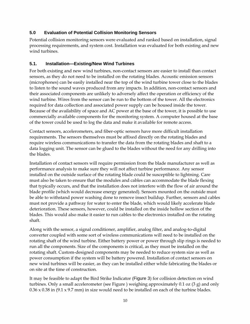
5.1. Installation—Existing/New Wind Turbines For both existing and new wind turbines, non-contact sensors are easier to install than contact sensors, as they do not need to be installed on the rotating blades. Acoustic emission sensors (microphones) can be easily installed near the top of the wind turbine tower close to the blades to listen to the sound waves produced from any impacts. In addition, non-contact sensors and their associated components are unlikely to adversely affect the operation or efficiency of the wind turbine. Wires from the sensor can be run to the bottom of the tower. All the electronics required for data collection and associated power supply can be housed inside the tower. Because of the availability of space and AC power at the base of the tower, it is possible to use commercially available components for the monitoring system. A computer housed at the base of the tower could be used to log the data and make it available for remote access.
Contact sensors, accelerometers, and fiber-optic sensors have more difficult installation requirements. The sensors themselves must be affixed directly on the rotating blades and require wireless communications to transfer the data from the rotating blades and shaft to a data logging unit. The sensor can be glued to the blades without the need for any drilling into the blades.
Installation of contact sensors will require permission from the blade manufacturer as well as performance analysis to make sure they will not affect turbine performance. Any sensor installed on the outside surface of the rotating blade could be susceptible to lightning. Care must also be taken to ensure that the modules and cables can accommodate the blade flexing that typically occurs, and that the installation does not interfere with the flow of air around the blade profile (which would decrease energy generated). Sensors mounted on the outside must be able to withstand power washing done to remove insect buildup. Further, sensors and cables must not provide a pathway for water to enter the blade, which would likely accelerate blade deterioration. These sensors, however, could be installed on the inside hollow section of the blades. This would also make it easier to run cables to the electronics installed on the rotating shaft.
Along with the sensor, a signal conditioner, amplifier, analog filter, and analog-to-digital converter coupled with some sort of wireless communications will need to be installed on the rotating shaft of the wind turbine. Either battery power or power through slip rings is needed to run all the components. Size of the components is critical, as they must be installed on the rotating shaft. Custom-designed components may be needed to reduce system size as well as power consumption if the system will be battery powered. Installation of contact sensors on new wind turbines will be easier, as they can be installed either while fabricating the blades or on site at the time of construction.
It may be feasible to adapt the Bird Strike Indicator (Figure 3) for collision detection on wind turbines. Only a small accelerometer (see Figure ) weighing approximately 0.1 oz (3 g) and only 0.36 x 0.38 in (9.1 x 9.7 mm) in size would need to be installed on each of the turbine blades.
10

These could be installed on the inside hollow section of the blades using adhesives. The rest of the electronic components of the BSI would be mounted on the turbine shaft. Cables would need to be run from the accelerometer to the BSI circuit board mounted on the turbine shaft. The BSI has all the components that need to be mounted on the rotating shaft in a small, custom, battery-operated package that could be modified for the wind turbine application. A small, custom-designed circuit board combines the signal conditioner, amplifier, analog filters, and microcontroller. A small credit card–sized plug-in wireless radio is used to communicate to a base station, which could be easily housed at the base of the tower. The overall size of the complete BSI sensor is 5.5 in (14.0 cm) x 4.25 in (10.8 cm) x 3 in (7.6 cm) and it weighs approximately 3 lbs (1.3 kg).
Figure 4. Accelerometer used in the BSI sensors
5.2. Signal Processing For both contact and non-contact sensors, the key to collision monitoring is the ability to detect and distinguish the response generated by the collision from all the environmental and operational noise that is normally present. A white paper published by the Renewable Energy Research Laboratory at University of Massachusetts at Amherst provides a detailed study of wind turbine acoustic noise (Rogers and Manwell 2004).
Wind turbine operational noise comes primarily from the blade and the gearbox. There are two main groups of vibration frequencies: gear mesh frequencies and bearing defect frequencies. In one typical machine, there are three fundamental gear mesh frequencies (and their harmonics) that result from the meshing of a sun gear, planets, a ring gear, and two other pinions and gears. There are several shafts supported by many bearings, each of which produces a set of four defect frequencies (outer race ball pass, inner race ball pass, cage, and element spin). In addition, wind turbines have mechanical and hydraulic systems that control the blade pitch, change the rotor direction, apply brakes, and lock the rotor under certain conditions. These intermittently operated systems also contribute to noise and vibration on an infrequent basis. The combination of mesh frequencies, harmonics, and bearing defect frequencies and intermittent noises can make frequency analysis a formidable task (Hatch 2004).
11

Environmental noise can also complicate analysis of the measured response and make collision detection difficult. The wind itself produces aerodynamic sound waves and vibration that generally increase with rotor speed. Varying loads on the turbine due to wind gusting produces additional vibration that could contribute to the difficulty. Rain and hail striking the turbine blades would produce vibration signals as well as sound waves, and thunder also produces sound waves that would be picked up by a microphone sensor.
Thus, all three sensor technologies must contend with changing levels of background “noise” from monitored turbine and adjacent turbines and the environment—whether vibration and strain, or sound waves. Accelerometers and fiber-optic sensors are more likely to detect collision, as they directly measure the response of collision with the rotor blade. Contact sensors would only need to contend with the net resultant vibration at the rotor blades. Accelerometers would only be monitoring vibration perpendicular to the rotating blades and thus might see limited vibration from turbine operations. Acoustic sensors should be able to detect the collision as long as the collision-produced sound waves are greater in magnitude than the background noise. The amplitude of vibration or sound wave generated from a bird or bat collision with the turbine blade will depend on the size of the animal, its velocity, and the distance from the collision site to the sensor. It is encouraging that acoustic sensors installed on the ground for monitoring avian activity at a proposed wind farm site in Nebraska have successfully recorded sound waves from three bird collisions with a guyed communication tower (Evans 1998).
A viable sensor system will need to adapt to the changing noise as the turbines start and stop and also to the variation in noise from different types of wind turbines. All sensors will have to be calibrated for the type of wind turbine to be monitored, as the continuous noise might be different. One approach for adapting to changing noise is to continuously monitor the signal from the sensors and use a changing threshold for detecting collision which automatically adjusts to the noise present.
5.3. Cost The cost differential between the three sensors is not great enough to preclude any one option. Equipment for the fiber-optic sensor is more expensive than for the accelerometer as it is a newer technology and would likely require the most customization and development. There are plenty of low-cost accelerometer sensors available in the market as they have already achieved very wide application. Acoustic sensors (microphones) by themselves are more expensive than accelerometers. However, because microphones are a non-contact option, the equipment does not need to be optimized and reduced in size, and off-the-shelf components could easily be integrated. Overall, acoustic sensors will be the cheapest option (combined equipment and installation costs) followed by accelerometer sensors.
All of the sensors can be moved from one site to another and reused after completion of study at one site with minimum refurbishment and recalibration. This should be kept in mind while evaluating the overall cost and benefit of developing a sensor system.
5.4. Ranking of Potential Collision Monitoring Sensors Acoustic emission sensors are predicted to be the most feasible system, based on ease of installation, cost, and signal processing requirements. Accelerometers are ranked second
12

primarily because of their installation requirements. If the rotor blades and gears are noisy enough to impair detection of sound waves from collision, then accelerometers would be the most feasible option. Fiber-optic sensors are expected to be the least feasible because of equipment cost: the off-the-shelf components are more expensive than the other technologies, and some components are so bulky they would need to be custom designed for mounting on a rotating turbine shaft.
13

A microphone sensor and related accessories were obtained on loan from PCB Electronics for couple of weeks. A half-inch (1.3-cm) free-field microphone (model 377A02) was selected for the initial trials (see Figure 5). Free-field microphones work best in open areas. Pressure field and random incidence field are other field types for microphones. Frequency range is the other key parameter to consider: the selected microphone had a frequency response range of 3.15 Hz to 20 kHz (see Table 1). A nose cone was mounted on the microphone to reduce the effect of wind blowing. A half-inch ICP preamplifier (model 426E01) was selected to amplify the small voltage signal from the microphone to a level that could be measured and digitized by an analog-to-digital converter. Table 2 provides specifications for the preamplifier selected for trial. The microphone simply screws on to the preamplifier.
To further evaluate the feasibility of using an acoustic emission sensor for bat/bird collision monitoring, preliminary tests were planned to be conducted on a wind turbine at the National Renewable Energy Laboratory (NREL) in Golden, Colorado. The plan was to collect data using a microphone while the wind turbine was in different stages of operation.
6.0 Acoustic Emission Sensor Laboratory Trial
The preamplifier was connected to a constant current power supply (signal conditioner) which had a built-in amplifier. The power supply used for this trial—available in-house—had four channels to connect up to four sensors. The same power supply could also be used for accelerometers. The output from the signal conditioner was connected to an analog-to-digital card housed inside a portable computer, which measured and stored the digitized signals from the analog-to-digital card. The power supply and the computer used are shown in Figure 6.
Figure 5. Microphone components selected for trial
14

Table 1. Specifications for different pre-polarized microphones available from PCB
Table 2. Specifications for preamplifiers
15
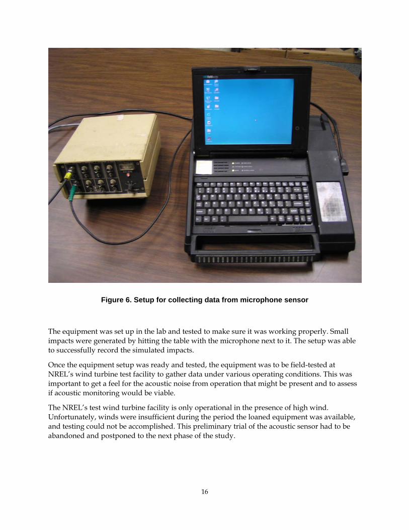
Figure 6. Setup for collecting data from microphone sensor
The equipment was set up in the lab and tested to make sure it was working properly. Small impacts were generated by hitting the table with the microphone next to it. The setup was able to successfully record the simulated impacts.
Once the equipment setup was ready and tested, the equipment was to be field-tested at NREL’s wind turbine test facility to gather data under various operating conditions. This was important to get a feel for the acoustic noise from operation that might be present and to assess if acoustic monitoring would be viable.
The NREL’s test wind turbine facility is only operational in the presence of high wind. Unfortunately, winds were insufficient during the period the loaned equipment was available, and testing could not be accomplished. This preliminary trial of the acoustic sensor had to be abandoned and postponed to the next phase of the study.
16
7.0 Conclusions and Recommendations
7.1. Conclusions Three candidate sensors were identified for automatic monitoring of wind turbines for bird and bat collisions. The sensor systems were evaluated based on their installation requirements, signal processing requirements, and overall system cost. The findings of the sensor system feasibility study are as follows:
The acoustic emission sensor (microphone) is the most viable sensor system overall, as it uses off-the-shelf components and has the easiest installation.
•
•
•
•
•
•
•
The accelerometer is ranked second, primarily because it must be installed on the rotor blades and thus requires associated hardware to be mounted on the rotor shaft. Accelerometer-based sensors developed by EDM to detect bird collisions with power lines could be adapted to the wind turbine application, thereby minimizing the development requirements. Fiber-optic sensors are considered the least feasible sensor system. Like accelerometers, they must be mounted directly on the rotating turbine blade. Fiber-optic technology is relatively new and the associated hardware is still somewhat bulky and expensive; custom hardware would be needed to enable practical installation on the rotor shaft. Turbine noise and environmental noise will be a key factor in the success of the acoustic emission sensor for detecting collisions. Blade vibration from turbine operation and environment will affect the success of using the accelerometer sensor. Field measurements are needed to further evaluate the feasibility of using acoustic sensors versus accelerometers for detecting bird/bat collisions with wind turbines.
7.2. Recommendations Further development of an automated collision detector should be carried out in two phases.
7.2.1. Phase II: Proof-of-concept testing Phase II is envisioned as a proof-of-concept phase where data will be collected on a test turbine at the National Renewable Energy Laboratory in Golden, Colorado. This phase will verify the acoustic monitoring approach and quickly evaluate the accelerometer approach. Proof-of-concept testing should be performed on more than one turbine located in a field of wind turbines, most closely simulating typical turbulent wakes from upwind turbines, adjacent turbine noise, and other typical factors. This phase will compare acoustic sensor versus accelerometer sensor sensitivity in detecting collisions in the presence of turbine noise—and thus determine if the acoustic sensor will be sensitive enough or if the study should focus on using more direct measurements from accelerometers. This phase will mostly utilize off-the-shelf components and consist of the following steps:
Assemble off-the-shelf components and develop an acoustic emission sensor system. Adapt the BSI for use as a possible accelerometer-based sensor system. Test the systems on wind turbines with simulated strikes.
17

Determine the sensitivity of the acoustic sensor system versus accelerometer-based system.
•
•
•
•
Recommend a prototype system for development.
7.2.2. Phase III: Prototype fabrication, field evaluation, and further development The next and final phase of development, Phase III, will consist of designing and assembling a prototype sensor system for field testing and evaluation of the system on couple of different types of wind turbines at a wind farm site. Based on field trial results, the prototype will be adjusted. A commercialization plan will also be developed as part of Phase III.
7.3. Benefits to California This project offers numerous benefits and meets the following PIER program objectives:
Developing cost-effective approaches to evaluating and resolving environmental effects of energy production. An automated sensor system to monitor wind turbine collisions will enable cost-effective study of bird/bat interactions with wind turbines. Such a system will greatly advance scientific understanding of the bird/bat collision problem and enable researchers to assess the efficacy of available tools and methodologies to mitigate the problem. Providing environmentally sound energy. Identifying effective methods to mitigate wind turbine impacts on wildlife will promote deployment of wind power, a clean, renewable energy source.
18

8.0 References
American Wind Energy Association (AWEA). 2005a. Wind industry eyes record year of growth, job creation. AWEA News Release, April 6, 2005. http://www.awea.org/news/news050426qmk.html.
American Wind Energy Association (AWEA). 2005b. Annual Rankings demonstrate continued growth of wind energy industry in the United States. AWEA News Release, May 12, 2005.
Anderson, R., N. Neumann, J. Tom, W.P. Erickson, M.D. Strickland, M. Bourassa, K.J. Bay, and K.J. Sernka. 2004. Avian Monitoring and Risk Assessment at the Tehachapi Pass Wind Resource Area. Subcontractor Report NREL/SR-500-36416. National Renewable Energy Laboratory, Golden, CO.
Anderson, R.J. Tom, N. Neumann, W.P. Erickson, M.D. Strickland, M. Bourassa, K.J. Bay, and K.J. Sernka. 2005. Avian Monitoring and Risk Assessment at the San Gorgonio Wind Resource Area. Subcontractor Report NREL/SR-500-38054. National Renewable Energy Laboratory, Golden, CO.
Beattie, A.G. 1997. Acoustic Emission Monitoring of a Wind Turbine Blade During a Fatigue Test. AIAA Aerospace Sciences Meeting, Reno, Nevada.
Benner, J.H.B., J.C. Berkhuizen, R.J. de Graff, and A.D. Postma. 1993. Impact of wind turbines on birdlife. Final Report No. 9247. Consultants on Energy and the Environment, Rotterdam, The Netherlands.
CEC PIER Report. 2003. Bird Strike Indicator/Bird Activity Monitor and Field Assessment of Avian Fatalities.
U.S. Department of Energy (DOE). 2005. Wind energy technologies. Energy Efficiency and Renewable Energy, Wind and Hydro Power Technologies Program. http://www1.eere.energy.gov/windandhydro/wind_how.html.
Evans, W.R. 1998. Application of Acoustic Bird Monitoring for the Wind Power Industry. Proceedings of the National Avian-Wind Power Planning Meeting III, San Diego, CA.
Howell, J.A. and J.E. Didonato. 1991. Assessment of avian use and mortality related to wind turbine operations, Altamont Pass, Alameda and Contra Costa Counties, California, September 1998 through August 1989. Final report submitted to U.S. Windpower, Inc., Livermore, CA.
Gauthreaux, S.A. 1984. Use of small mobile radars to detect, monitor, and quantify bird movements. Proceedings, Conference and Training Workshop on Wildlife Hazards to Aircraft, Charleston, South Carolina, May 22–25, 1984. p. 121–131.
Johnson, G.D., D.P. Young, Jr., W.P. Erickson, M.D. Strickland, R.E. Good and P. Becker. 2000. Avian and bat mortality associated with the initial phase of the Foote Creek Rim Windpower Project, Carbon County, Wyoming: November 3, 1998 – October 31, 1999.
19

Technical report prepared by West, Inc. for SeaWest Energy Corporation and Bureau of Land Management, Cheyenne, WY. 32 pp.
Kerlinger, P., R. Curry, L. Culp, A. Jain, C. Wilkerson, B. Fisher, and A. Hasch. 2006. Post-construction avian and bat fatality monitoring study for the High Winds wind power project, Solano County, California: Two year report. Curry and Kerlinger, L.L.C. McLean, VA.
Melton, R.E., B.M. Sabol, and A. Sherman (2005) “Poor man's missile tracking technology: Thermal IR detection and tracking of bats in flight.,” Proceedings International Society of Optical Engineering (SPIE) vol. 5811, pages: 24-33
Musters, C.J.M., and G.J.C. van Zuylen, and W.J. ter Keurs. 1991. Volgels en windmollens bij de kreekraksluizaen (Bird casualties caused by a wind energy project in an estuary; English translation). Rapport, Vakgroep Milieubiologie, Rijksuniversiteit Leiden, Leiden, The Netherlands.
National Wind Coordinating Committee (NWCC) Wildlife Workgroup. 2004. Wind turbine interactions with birds and bats: A summary of research results and remaining questions. Fact Sheet, 2nd ed. National Wind Coordinating Committee consensus document. Washington, D.C.
Orloff, S., and A. Flannery. 1996. A continued examination of avian mortality in the Altamont Pass Wind Resource Area. Report by BioSystems Analysis, Inc. (Tiburon, CA) to the California Energy Commission.
Orloff, S., and A. Flannery. 1992. Wind turbine effects on avian activity, habitat use, and mortality in Altamont Pass and Solano County Wind Resource Areas: 1989-1991. Final Report by BioSystems Analysis, Inc. (Tiberon, CA) to the California Energy Commission.
Rademakers, L.W. M., M.T W. Vebruggen, P.A. van der Werff, H. Korterink, D. Richon, P. Rey, and F. Lancon. 2004. Fiber optic blade monitoring. Paper presented at European Wind Energy Conference (EWEC), November 22–25, 2004, London.
Rogers, A.L., and J.F Manwell. 2004. Wind Turbine Noise Issues. White paper by Renewable Energy Research Laboratory, University of Massachusetts at Amherst, Amherst, MA.
Smallwood, K.S. and C. G. Thelander. 2004. Developing methods to reduce bird mortality in the Altamont Pass Wind Resource Area. Final report by BioResource Consultants to the California Energy Commission, Public Interest Energy Research-Environmental Area.
Spruyt, J.A, and P. vanDorp. 1996. Detection of birds by radar. Physics and Electronics Laboratory RVO-TNO Report: FEL-95-A244; TDCKTD95-1638, August 1996. The Hague, Netherlands. 43 p.
Sterner, D. 2002. A Roadmap for PIER Research on Avian Collisions with Wind Turbines in California. California Energy Commission Publication #500-02-070F.
Verhoef J.P., C.A. Westr, P.J. Eecen, R.J. Nijdam, and H. Korterink. 2003. Development and First Results of a Bird Impact Detection System for Wind Turbines. EWEC, Madrid, Spain.
20

Waldl, H., and T. Pahlke. 2001. Wind farm surveillance and video monitoring. Paper presented at European Wind Energy Conference (EWEC), July 1–7, 2001, Copenhagen.
21

22