development of a matlab data acquisition and control ... · of both the pic microcontroller and...
TRANSCRIPT

AC 2007-1838: DEVELOPMENT OF A MATLAB DATA ACQUISITION ANDCONTROL TOOLBOX FOR PIC MICROCONTROLLERS
Sang-Hoon Lee, Polytechnic UniversitySANG-HOON LEE was born in Seoul, Korea. He received the B.S. degree in MechanicalEngineering from Sung Kyun Kwan University, Seoul, Korea, in 1996 and the M.S. degree inMechanical Engineering from Polytechnic University, Brooklyn, NY, in 2002. From 1996 to1997, he worked for Samsung Engineering Co., Ltd. in Korea. He is currently continuing researchat Polytechnic University as a doctoral student. His research interests include linear/nonlinearcontrol and mechatronics.
Anshuman Panda, Polytechnic UniversityANSHUMAN PANDA was born in New Delhi, India. He is currently pursuing a dual B.S/M.S.degree in Electrical Engineering and expects to graduate in June 2007. He is a member of TauBeta Pi. He has worked as a teaching and research assistant with responsibilities in the area ofmechatronics.
Vikram Kapila, Polytechnic UniversityVIKRAM KAPILA is an Associate Professor of Mechanical Engineering at PolytechnicUniversity, Brooklyn, NY, where he directs an NSF funded Web-Enabled Mechatronics andProcess Control Remote Laboratory, an NSF funded Research Experience for Teachers Site inMechatronics that has been featured on WABC-TV and NY1 News, and an NSF funded GK-12Fellows project. He has held visiting positions with the Air Force Research Laboratories inDayton, OH. His research interests are in cooperative control; distributed spacecraft formationcontrol; linear/nonlinear control with applications to robust control, saturation control, andtime-delay systems; closed-loop input shaping; spacecraft attitude control; mechatronics; andDSP/PC/microcontroller-based real-time control. He received Polytechnic’s 2002 Jacob’sExcellence in Education Award and 2003 Distinguished Teacher Award. In 2004, he was selectedfor a three-year term as a Senior Faculty Fellow of Polytechnic University’s Othmer Institute forInterdisciplinary Studies. He has edited one book and published four chapters in edited books, 1book review, 39 journal articles, and 81 conference papers. He has mentored 67 high schoolstudents, 38 high school teachers, 10 undergraduate summer interns, and seven undergraduatecapstone-design teams. In addition, he has supervised three M.S. projects, two M.S. thesis, andthree Ph.D. dissertations.
Hong Wong, Polytechnic UniversityHONG WONG was born in Hong Kong, China. In June of 2000 and 2002, he received the B.S.and M.S. degrees, respectively, in Mechanical Engineering from Polytechnic University,Brooklyn, NY. He is a member of Pi Tau Sigma and Tau Beta Pi. He worked for the Air ForceResearch Laboratories in Dayton, OH, during the summers of 2000 and 2001. He is currently adoctoral student at Polytechnic University and expects to graduate in June 2007. His researchinterests include control of mechanical and aerospace systems.
© American Society for Engineering Education, 2007
Page 12.512.1

Abstract—This paper presents a personal computer (PC)-based data acquisition and control tool that uses a Peripheral Interface Controller (PIC) microcontroller, Matlab, and Simulink. Specifically, a library of PIC microcontroller functions for Simulink is created. Moreover, the PIC microcontroller and Matlab are merged, by exploiting their serial communication capability, to produce an inexpensive data acquisition and control platform. Finally, the efficacy of this data acquisition and control platform is illustrated by performing angular position control of a DC
motor.
1. Introduction
Data acquisition and control boards are essential for interfacing sensors/actuators with decision
making devices such as a PC. Thus, data acquisition and control boards are used in
monitoring/instrumentation applications involving machinery, process, environment, etc., and in
automatic control applications. Even though a variety of data acquisition and control boards have
become widely available in the last 15 years, the systems that target the educational sector and
provide support for icon-based programming environments, such as LabVIEW1 and Simulink,2
tend to be quite expensive (over $500 to several thousand dollars). Moreover, instructional labs
generally may not require the intrinsic high-performance features of many of the commercially
available data acquisition and control boards (e.g., high sampling rates, high resolution analog to
digital converters, etc.) for the typical electro-mechanical laboratory experiments. This paper
proposes a microcontroller-based data acquisition and control system that is particularly suitable
for educators interested in developing lab experiments that do not require high-cost, high-
performance data acquisition hardware and yet can benefit from the icon-based programming
environment of Simulink.
Several recent papers have focused on interfacing low-cost microcontrollers (such as Basic
Stamp 2 (BS2) and PIC) with icon-based programming environments such as LabVIEW and
Simulink. Specifically, Refs. 3—5 concentrated primarily on endowing microcontrollers with
graphical user interface (GUI) capability by exploiting the GUI tools of LabVIEW and Simulink.
However, the methodology of Refs. 3—5 requires manually programming the microcontroller
for all sensing, control computation, and actuation tasks and for serial communication with the
GUI running on the PC. To program a PIC microcontroller or a BS2 microcontroller using PIC
assembly programming language or PBasic programming language, respectively, requires
knowledge and experience with the syntax of these languages and is often tedious.
This paper proposes a PIC microcontroller based low-cost data acquisition and control system
that exploits Matlab and Simulink as the key software components for implementing data
acquisition and control algorithms using a block-diagram format. Specifically, the paper exploits
a newly developed library of PIC functions for Simulink and the serial communication capability
Development of a Matlab Data Acquisition and Control Toolbox
for PIC Microcontrollers
Page 12.512.2

of both the PIC microcontroller and Matlab to produce a seamless integration between them. The
framework of this paper completely obviates the need to manually program the PIC
microcontroller by creating a library of PIC microcontroller functions for Simulink. Specifically,
the data acquisition and control toolbox of this paper facilitates (i) automatic generation of
proper PIC assembly codes for a variety of sensors and actuators, (ii) automatic programming of
the PIC microcontroller, and (iii) data communication between the PIC microcontroller and
Matlab. In an instructional laboratory, this approach allows instructors and students to focus on
hardware-in-the-loop implementation, experimental validation, and industry-style rapid control
prototyping. Finally, this paper is in the spirit of Ref. 6, which provided a Matlab data
acquisition and control toolbox for the BS2 microcontrollers. However, whereas the BS2
microcontroller costs over $45 and includes only digital input/output (I/O) functionality, thus
requiring external analog to digital converters (ADCs) to interface with analog sensors, the
PIC16F74 microcontroller, used in this paper, costs under $5 and includes built-in ADC
functionality.
This paper is organized as follows. Section 2 describes the PIC microcontroller and the related
development hardware. Section 3 describes the software environment used in this paper. Section
4 gives details concerning the software integration of Simulink with the PIC microcontroller.
Section 5 illustrates the functionality and capability of the data acquisition and control hardware
and software of this paper by performing position control of a DC motor. Finally, Section 6
provides some concluding remarks.
2. Hardware Environment
The main components of the data acquisition and control hardware of this paper are a PIC
microcontroller, a PIC-PG2C programmer, and a PIC development board. A DB-9 serial cable is
used to interface the programmer/development board to a PC which hosts the Matlab data
acquisition and control toolbox. Specifically, the DB-9 cable allows (i) programming the PIC
microcontroller from the PC and (ii) data communication between the PIC and the PC. In this
paper, an IBM-compatible Pentium 4 PC running Microsoft Windows XP operating system is
used. See Figure 1 for a pictorial representation of the aforementioned hardware environment.
PIC development board
PIC-PG2C programmer
PC
PIC microcontroller
DB-9 serial cable
Figure 1: Hardware environment
Page 12.512.3

2.1.Peripheral Interface Controller (PIC)
PIC microcontrollers, developed, manufactured, and marketed by Microchip, Inc.,7 are small,
inexpensive controllers that include a processor and a variety of peripherals such as memory,
timers, and I/O functions on an integrated circuit (IC). PIC microcontrollers are widely popular
among educational, hobby, and industrial users who can select from more than 100 varieties of
PICs one that suits their application and functional needs. In contrast to many other
microcontrollers, PICs are quite versatile since their I/O pins can be assigned desired
functionality (e.g., ADC, USART*) under program control. Moreover, using an appropriate
crystal oscillator, PIC microcontrollers can be operated at clock speeds of 32 kHz—20 MHz.
The PIC assembly language, consisting of a 35 single-word instruction set, is used to program
PIC microcontrollers. See Ref. 8 for more details on hardware and software features of PIC
microcontrollers.
The data acquisition and control platform of this paper uses a PIC16F74,9 a 40-pin CMOS
FLASH-based, 8-bit, mid-range (14-bit instruction word length) microcontroller. Pertinent
specifications of PIC16F74 include: 2—5.5 Volt direct current (VDC) voltage input; 25mA
current sink/source capability at each I/O pin; 4 Kbytes of FLASH program memory; 192 bytes
of data memory; and 33 digital I/O pins organized in 5 ports (A—E) of I/Os that can be assigned
as 8-bit ADCs, Capture/Compare/PWMs† (CCPs), 3-wire Serial Peripheral Interfaces (SPIs), 2-
wire Inter-Integrated Circuit (I2C) buses, USART ports, etc. In this paper, five of the six I/O pins
of port A and three I/O pins of port E are reserved for eight 8-bit ADCs, eight I/O pins of port B
are reserved for eight digital inputs, two of the eight I/O pins of port C are reserved for two
PWM outputs, and eight I/O pins of port D are reserved for eight digital outputs. Finally, an
external 20 MHz high-speed crystal oscillator is used to supply operating clock cycles to the
PIC.
2.2. PIC-PG2C Programmer
The user specified PIC program, which is created on a PC, is downloaded from the PC to a
PIC microcontroller by serial communication. Serial communication between the PC and the PIC
microcontroller is enabled by using a DB-9 serial connection between the PC and a PIC
development programmer that hosts the PIC microcontroller. Two widely used PIC development
programmers are Microchip’s PICSTART Plus and Olimex’s PIC-PG2C.10 In this paper, the
handy and low-cost PIC-PG2C programmer (see Figure 2) is used. In contrast to other PIC
programmers, the PIC-PG2C programmer receives power from the PC’s serial port thus
obviating the need for any additional power supply. Finally, the PIC-PG2C programmer requires
IC-Prog,11 a freely available software, to download PIC HEX code to the PIC microcontroller.
Note that the PIC HEX code is obtained from the PIC assembly code by using the MPASM
assembler,12 also available for free.
* Universal synchronous/asynchronous receiver and transmitter. † Pulse width modulation.
Page 12.512.4

(a) (b)
Figure 2: (a) PIC-PG2C and a PIC and (b) PIC-PG2C with a PIC mounted
2.3.PIC Development Board
The PIC development board of this paper is created on a breadboard and consist of (i) a
PIC16F74 microcontroller; (ii) a 20MHz crystal oscillator to supply operating clock cycles to the
PIC microcontroller; (iii) the RS232 driver/receiver circuitry for serial data communication with
the PC; (iv) a DB-9 connector; and (v) a breadboard area for custom circuits and easy
connectivity between the PIC microcontroller and sensors/actuators. Note that Maxim’s
MAX232 IC13 with five 1µF capacitors serves as the RS232 driver/receiver to transform voltage
levels between PC-based logic (±12VDC) and the PIC microcontroller-based logic (0VDC and
5VDC).
3. Software Environment
The software environment for this paper consists of Matlab version 6.5, Simulink version 5,
the PIC assembly language, a newly developed Simulink library for the PIC microcontroller,
MPASM, and IC-Prog. As previously discussed, the PIC assembly language is a primitive
programming language consisting of an instruction set of 35 single-words. Matlab is an
interactive technical computing software and Simulink is Matlab’s icon-based programming
environment. The Matlab toolbox for the PIC microcontroller consists of a Simulink library of
PIC microcontroller functions such that based on the user selected configuration of individual
I/O pins of the PIC microcontroller, Simulink automatically produces and downloads the proper
PIC assembly code to the microcontroller. Moreover, the Matlab toolbox also allows data
communication between the PIC microcontroller and Matlab. Thus, the Matlab toolbox for the
PIC microcontroller completely obviates the need to manually program the PIC microcontroller.
Note that the Matlab toolbox automatically executes the assembler program MPASM and the
download program IC-Prog, both of which usually require command line execution. See Refs. 12
and 14 for details on programming the PIC microcontroller in command line via serial
communication. The Matlab toolbox for the PIC microcontrollers has two main components: (i)
a Simulink model file named Template.mdl and (ii) a block library named PIC library.
3.1. Template.mdl
The Template.mdl model file (see Figure 3) is a predesigned Simulink model file which must
be used to design Simulink block diagrams for interaction with the PIC microcontroller. A
Page 12.512.5
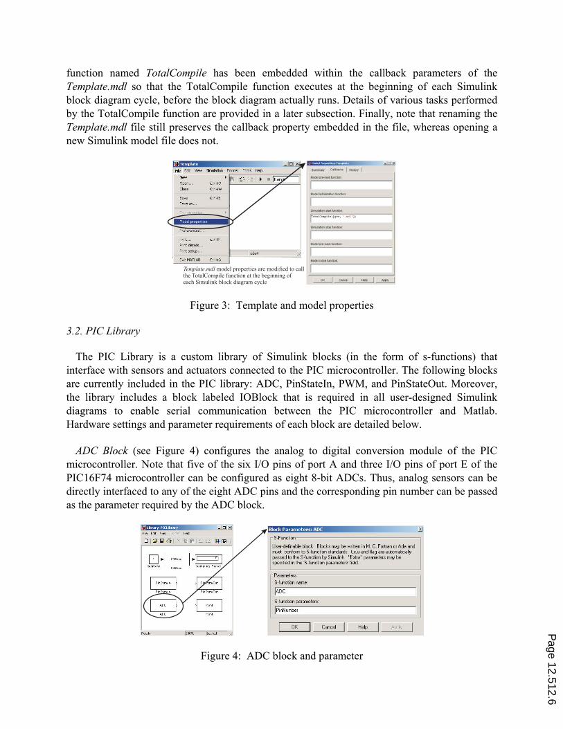
function named TotalCompile has been embedded within the callback parameters of the
Template.mdl so that the TotalCompile function executes at the beginning of each Simulink
block diagram cycle, before the block diagram actually runs. Details of various tasks performed
by the TotalCompile function are provided in a later subsection. Finally, note that renaming the
Template.mdl file still preserves the callback property embedded in the file, whereas opening a
new Simulink model file does not.
Template.mdl model properties are modified to callthe function at the beginning ofeach Simulink block diagram cycle
TotalCompile
Figure 3: Template and model properties
3.2. PIC Library
The PIC Library is a custom library of Simulink blocks (in the form of s-functions) that
interface with sensors and actuators connected to the PIC microcontroller. The following blocks
are currently included in the PIC library: ADC, PinStateIn, PWM, and PinStateOut. Moreover,
the library includes a block labeled IOBlock that is required in all user-designed Simulink
diagrams to enable serial communication between the PIC microcontroller and Matlab.
Hardware settings and parameter requirements of each block are detailed below.
ADC Block (see Figure 4) configures the analog to digital conversion module of the PIC
microcontroller. Note that five of the six I/O pins of port A and three I/O pins of port E of the
PIC16F74 microcontroller can be configured as eight 8-bit ADCs. Thus, analog sensors can be
directly interfaced to any of the eight ADC pins and the corresponding pin number can be passed
as the parameter required by the ADC block.
Figure 4: ADC block and parameter
Page 12.512.6

PinStateIn Block (see Figure 5) configures the I/O pins of port B of the PIC16F74
microcontroller to serve as digital inputs. Specifically, each of the eight pins of port B can serve
as a digital input by passing the corresponding pin number as a parameter to the PinStateIn
block.
Figure 5: PinStateIn block and parameter
PWM Block (see Figure 6) configures PWM modules of the PIC microcontroller. Specifically,
two of the eight I/O pins of port C of the PIC16F74 microcontroller can be configured as PWM
outputs. Since the PIC16F74 microcontroller does not include a digital to analog converter, in
this paper, we use the PWM outputs to produce the required analog voltage output by varying
the duty cycle of the PWM signal. Thus, two analog actuators can be interfaced to the two I/O
pins of port C that produce PWM outputs and the corresponding pin numbers are passed as the
parameter required by the PWM block.
Figure 6: PWM block and parameter
PinStateOut Block (see Figure 7) configures the I/O pins of port D of the PIC16F74
microcontroller to serve as digital outputs. Specifically, each of the eight pins of port D can serve as a digital output by passing the corresponding pin number as a parameter to the PinStateOut block.
Page 12.512.7

Figure 7: PinStateOut block and parameter
IOBlock is necessary for every Simulink block diagram that requires interaction with the PIC
microcontroller. It performs the following tasks: (i) initiate serial communication between
Matlab and the PIC microcontroller when the Simulink block diagram is initially executed, (ii)
transmit and receive data between Matlab and the PIC microcontroller while the Simulink block
diagram is running, and (iii) terminate serial communication between Matlab and the PIC
microcontroller when the Simulink block diagram is stopped. The callback function properties of
the IOBlock include start_serial and stop_serial functions that initiate and terminate serial
communication, respectively. In the Simulink block diagram, the IOBlock is programmed to
have the first priority for execution. This ensures that all sensor and actuator data in Matlab are
first received and sent, respectively, which then is used by the corresponding sensor and actuator
blocks in the Simulink block diagram.
Several Simulink blocks, such as an integrator block, require the knowledge of sampling
period for their proper use in a given Simulink block diagram. In this paper, the IOBlock is used
to determine, experimentally, the sampling period of the Simulink block diagram. Here,
sampling period is defined as the time required to execute one entire cycle of the Simulink block.
The IOBlock determines the sampling period by averaging the time taken to run a user-specified
number of cycles of the Simulink block diagram. An averaged sampling period is not expected to
provide the exact sampling period for each Simulink block cycle and its use is not recommended
when hard real-time constraints are to be enforced.
Figure 8: IOBlock and parameters
Page 12.512.8

4.Integration of Simulink and PIC
When blocks from the PIC Library are used in the Template.mdl model file, a sequence of
operations specified by the TotalCompile function are performed before the Simulink block
diagram begins to run. The main role of the TotalCompile function is to program the PIC
microcontroller and to facilitate serial communication between Matlab and the PIC
microcontroller. As seen in Figure 3, the TotalCompile function is set as a “Simulation start
function” of “Callbacks” option in the “Model properties” of Template.mdl.
The TotalCompile function performs the following sequence of tasks. First, global variables
are declared and used to share data with Simulink blocks of PIC library. Second, sensor and
actuator blocks used in the Simulink diagram are matched with the corresponding Simulink
blocks in the PIC library. Furthermore, each block is categorized as a sensor or an actuator and
its name is stored in an array of sensor/actuator structures with the specified block properties.
The sensor/actuator array information is also used when data is serially communicated. Third,
using the sensor/actuator block information gathered in the previous step, a PIC assembly code is
generated. This step is facilitated by the fact that for each sensor/actuator block in the PIC
Library the corresponding PIC assembly code has already been created and saved as an m-file.
Fourth, a portion of the IOBlock Matlab code is generated to allow serial communication
between Matlab and the PIC microcontroller. This Matlab code sends and receives the same
amount of data that the PIC microcontroller receives and sends, respectively. Fifth, the PIC
microcontroller is programmed in two steps: (i) using the MPASM assembler the PIC assembly
code, generated in step 3 above, is converted to the corresponding PIC HEX code and (ii) using
the IC-Prog the PIC HEX code is downloaded to a PIC microcontroller installed on a PIC-PG2C
programmer. Figure 9 shows a flow diagram of the three steps involved in programming the PIC
microcontroller.
PIC assembly code isgenerated by TotalCompile
PIC assembly code is convertedto by MPASMPIC HEX code
PIC HEX code is downloadedby IC-Prog via the serial port
Figure 9: Flow diagram of programming the PIC microcontroller
After the TotalCompile function completes its sequence of tasks, the Simulink block diagram
begins to execute when the user confirms that the PIC microcontroller has been removed from
the PIC-PG2C programmer and properly installed onto the PIC development board. At this stage,
serial communication between the PIC microcontroller and Matlab also begins. If Simulink is
stopped and needs to be run again, without any changes to the configuration of the PIC
Page 12.512.9

microcontroller I/O pins, then the PIC microcontroller need not be reprogrammed.
Once the Simulink block diagram begins to execute, the PIC and PC exchange sensory
feedback and actuator commands via serial data communication. Specifically, special function 8-bit PIC registers are used for the serial communication of sensor/actuator data.4, 9 The IOBlock
receives/transmits data from/to the PIC and stores the data in sensor/actuator global variables.
5.Example – DC Motor Control
To illustrate the functionality and capability of the data acquisition and control hardware and
software of this paper, position control of a DC motor is performed. Specifically, a DC motor
test-bed is interfaced with a PIC-based data acquisition and control board and a control algorithm
is implemented using Simulink and the Matlab toolbox for the PIC microcontroller. The DC
motor test-bed, shown in Figure 10, consists of an armature controlled DC motor, instrumented
with a continuous rotation potentiometer, and a power module. The potentiometer output is used
to obtain the necessary feedback signals and to provide a real-time display of the angular
position of the motor. To control the angular position of the DC motor, the PIC microcontroller
applies a controlled voltage signal produced by a control algorithm running on Simulink.
Digitized sensor datafrom PIC
Control outputfrom Simulink
Analog sensor data
Analog control output
DC motor and power module PIC development board Simulink block diagram
Figure 10: Hardware layer schematic
In this paper, a proportional-integral-derivative (PID) controller15 is used for the angular
position control of the DC motor. The functionality of various Simulink blocks used in Figure 10
(see Figure 11 for an exploded view) is as follows. The ADC_Pot block serves as an ADC block
to convert the analog output of the potentiometer into an 8-bit digital data. The PID Controller
block encapsulates the standard PID control algorithm. The inputs to the PID Controller block
are (i) the desired angular position of the DC motor and (ii) the potentiometer signal (the
digitized output of ADC_Pot block). The output of the PID Controller block is a controlled
voltage signal to be applied to the motor. In Figure 11, the PID Controller block output is
processed by the PWM_Motor block which serves as a PWM block. Note that the power
amplifier module of the DC motor shown in Figure 10 requires a ±5VDC to drive the DC motor.
Accordingly, the PID control algorithm outputs a ±5VDC control signal. However, the PIC
microcontroller can output only 0—5 VDC using the PWM output. Thus, the ±5VDC output of
the PID controller is appropriately transformed to command the PWM_Motor block with a 0—5
VDC command signal. Finally, by processing the PWM output from the PIC microcontroller
Page 12.512.10
using a simple operational amplifier based circuitry, the 0—5 VDC PWM output is converted
into a ±5VDC signal for input to the power amplifier module.
Figure 11: Simulink block diagram: Exploded view
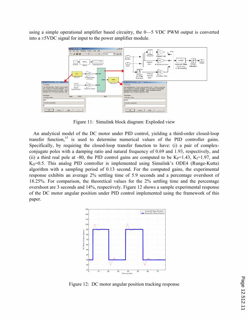
An analytical model of the DC motor under PID control, yielding a third-order closed-loop
transfer function,15 is used to determine numerical values of the PID controller gains.
Specifically, by requiring the closed-loop transfer function to have: (i) a pair of complex-
conjugate poles with a damping ratio and natural frequency of 0.69 and 1.93, respectively, and
(ii) a third real pole at -80, the PID control gains are computed to be KP=1.43, KI=1.97, and
KD=0.5. This analog PID controller is implemented using Simulink’s ODE4 (Runge-Kutta)
algorithm with a sampling period of 0.13 second. For the computed gains, the experimental
response exhibits an average 2% settling time of 5.9 seconds and a percentage overshoot of
18.25%. For comparison, the theoretical values for the 2% settling time and the percentage
overshoot are 3 seconds and 14%, respectively. Figure 12 shows a sample experimental response
of the DC motor angular position under PID control implemented using the framework of this
paper.
0 10 20 30 40 50 60 7010
20
30
40
50
60
70
80
90
100
110
120
130
Time (seconds)
DC
Moto
r P
osi
tion (
deg
rees
)
Actual DC Motor PositionDesired DC Motor Position
Figure 12: DC motor angular position tracking response
Page 12.512.11

6.Conclusion
This paper provided an overview of a low-cost data acquisition and control toolbox that
consists of the newly developed Simulink library for PIC microcontrollers. Serial
communication capabilities of the PIC microcontroller and Matlab allowed programming of the
PIC microcontroller from Matlab and exchange of sensory data and actuation signals between
the PIC microcontroller and Matlab. The capabilities of this low-cost data acquisition and
control system were illustrated through a DC motor angular position control experiment.
Acknowledgements
This work is supported in part by the National Science Foundation under an RET Site grant 0227479 and a GK—12 Fellows grant 0337668 and the NASA/NY Space Grant Consortium under grant 48240-7887.
References
[1] Online: http://www.ni.com/labview/, website of National Instruments Corp., developer and distributor of
LabVIEW.
[2] Online: http://www.mathworks.com/, website of MathWorks Inc., developer and distributor of Matlab and
Simulink.
[3] C. J. Radcliffe, “The Basic Stamp II and LabVIEW,” http://www.parallax.com/dl/sw/labviewbs2.pdf.
[4] S.-H. Lee, Y.-F. Li, and V. Kapila, “Development of a Matlab-Based Graphical User Interface for PIC
Microcontroller Projects,” Proceedings of the American Society of Engineering Education Conference, Salt
Lake City, UT, Session 2220, 2004.
[5] Y. F. Li, S. Harari, H. Wong, and V. Kapila, “Matlab-Based Graphical User Interface Development for Basic
Stamp 2 Microcontroller Projects,” Proceedings of the American Control Conference, Boston, MA, pp. 3233–
3238, 2004.
[6] A. Panda, H. Wong, V. Kapila, and S.-H. Lee, “Two-Tank Liquid Level Control Using a Basic Stamp
Microcontroller and a Matlab-Based Data Acquisition and Control Toolbox,” Proceedings of the American
Society of Engineering Education Conference, Chicago, IL, Session 3520, 2006.
[7] Online: http://www.microchip.com/, website of Microchip Technology, Inc.
[8] M. Predko, Programming and Customizing Picmicro® Microcontrollers. McGraw-Hill, New York, NY, 2002.
[9] Online: http://ww1.microchip.com/downloads/en/DeviceDoc/30325b.pdf, website of Microchip Technology,
Inc., (access link for PIC16F74 datasheet).
[10] Online: http://www.olimex.com/dev/pic-pg2.html, website of Olimex Ltd., (access link for PIC-PG2C Serial
Port Programmer).
[11] Online: http://www.ic-prog.com/, website of IC-Prog software.
[12] Online: http://ww1.microchip.com/downloads/en/DeviceDoc/33014J.pdf, website of MPLAB Integrated
Development Environment for the PIC microcontroller programming (access link for the MPASM assembler
user’s guide for PIC microcontrollers).
[13] Online: http://pdfserv.maxim-ic.com/en/ds/MAX220-MAX249.pdf, website of Maxim Integrated Products,
(access link for MAX232 datasheet).
[14] Online: http://www.ic-prog.com/cmdline.txt, website of IC-Prog software (access link for the command line
programming for PIC microcontrollers).
[15] R. C. Dorf and R. H. Bishop, Modern Control Systems. Addison Wesley, Menlo Park, CA, 2005.
Page 12.512.12