development of a new hybrid compressible solver inside...
TRANSCRIPT

Development of a new hybrid compressible solver
inside the CFD elsA software
Guillaume Puigt�
CERFACS
Michel Gazaixy
ONERA
Marc Montagnac�
CERFACS
Marie-Claire Le Papey
ONERA
Marta de la Llave Platay
ONERA
Claude Marmignony
ONERA
Jean-Francois Boussuge�
CERFACS
Vincent Couailliery
ONERA
A new fully integrated environment for compressible ow simulation on structured andunstructured zones coexisting within the same hybrid mesh is presented. This environmentoriginates from the existing elsA a CFD software tool, developed by ONERA and CERFACSfor structured grids, and widely used both in industry and research.
Some con�gurations can not be easily addressed with a fully structured mesh approach.An e�cient way to overcome this drawback is to combine structured and unstructuredzones in a single hybrid mesh. Structured zones are kept for sake of accuracy in boundarylayers, wall clock e�ciency and low memory consumption. Unstructured zones enable aneasier mesh generation / adaptation process.
This paper describes the extension of elsA to unstructured multi-element zones com-posed of hexahedra, tetrahedra, prisms and pyramids. A key feature is the treatmentof structured / unstructured zone interfaces, performed with a mismatched abutting gridinterface algorithm.
We demonstrate that the Object-Oriented (OO) programming approach is useful ande�cient to integrate unstructured data structures and numerical methods into the originalsoftware to form a single computational CFD kernel.
Software design, numerical algorithm, structured/unstructured block interface treat-ment, CPU e�ciency and parallel scalability, are discussed. Finally, validation examplesdemonstrating the project status are given.
I. Introduction
Most Computational Fluid Dynamics (CFD) codes may be classi�ed into two branches depending on themeshing methodology b, either structured or unstructured. Both mesh types have their speci�c advantages.
The main advantages of structured grids are, �rst, their ability to capture the anisotropy of boundarylayer regions, where high-aspect ratio cells are required, and, secondly, structured numerical techniqueshelping to improve performance and robustness (for example implicit smoothing operator, or the structuredway of coarsening meshes for the multigrid procedure). Over the years, engineers have de�ned best practicesto build such meshes on relatively complex CAD model. Since the mesh generation can be complex andtime-consuming, large e�orts have been dedicated to ease the meshing process. Widely used approaches arechimerac grids,1 or mismatched abutting interfaces2 (in CGNS3 notationd) between blocks. These techniques
�CERFACS, Computational Fluid Dynamics, 42 avenue Coriolis, 31057 TOULOUSE CEDEX (FRANCE).yONERA, Computational Fluid Dynamics and Aeroacoustics, BP72 29 avenue de la Division Leclerc 92322 CHATILLON
CEDEX (FRANCE).aensemble logiciel pour la simulation en A�erodynamiqueba mesh is de�ned as the complete set of individual grid associated to each zone (CGNS notation)cor oversetdalso called patched grid
1 of 19
American Institute of Aeronautics and Astronautics
20th AIAA Computational Fluid Dynamics Conference27 - 30 June 2011, Honolulu, Hawaii
AIAA 2011-3379
Copyright © 2011 by ONERA. Published by the American Institute of Aeronautics and Astronautics, Inc., with permission.

are now mature, and a huge amount of experience is available. Note also that several recent workshops4,5
have demonstrated faster mesh convergence when using structured mesh, specially for high-Reynolds number ows. However, the structured grid generation for complex geometriese is a time-consuming task due to thepossible need of breaking the domain manually into several blocks.
For really highly complex CAD models, a common belief inside the CFD community is that is is easierto switch to unstructured mesh technology. However, the process being generally more or less automatic,solution accuracy may be reduced due to the presence of skewed elements in sensitive regions like boundarylayers. A way to overcome this drawback is to authorize unstructured grids composed of di�erent elementshapes with hexahedra and prisms in the anisotropic ow region, tetrahedra elements where the ow isisotropic, and pyramids in the bu�er region from four-node faces to three-node element faces. In the fol-lowing, such multi-element grids are called mixed-element gridsf. Their main drawbacks, however, are thememory overhead associated with storing grid connectivity information and the computer time associatedwith indirect addressing. In addition, due to the lack of grid structure, it is di�cult to implement simpleimplicit schemes such as approximate factorization, while explicit schemes su�er from slow convergence.
It is therefore tempting to try to associate both techniques, in order to bene�t from the advantages ofboth techniques, and hopefully avoiding most of the de�ciencies of each approach. Moreover, to reducedevelopment costs as well as to minimize end user’s learning time, it would be desirable to have a single codebeing able to handle structured, unstructured and hybrid meshes.
Thus, this paper presents a new unstructured solver, together with the coupling algorithm with thestructured regions. This unstructured solver is incorporated inside the CFD tool elsA,6{9 developed byONERA since 1997 and co-developed by CERFACS since 2001,10 and used by a large user community inboth research and industry. The extended elsA tool can take into account simultaneously both structuredand unstructured zones. The structured and unstructured solvers share the same CFD kernel, avoidingmost code duplication with the associated maintenance nightmare. Structured zones bene�t from the higheraccuracy, numerical e�ciency and better usage of modern processor memory cache, while unstructured zonesallow to keep the meshing process in the most complex regions manageable.
The development in elsA of hybrid mesh capabilities relies on a strong cooperative e�ort between Oneraand Cerfacs.11
To the authors’s knowledge there are up to now no fully satisfying mesh generation software handling fullyhybrid structured/unstructured mesh. Moreover, based on our experience in structured mesh generation,it is likely that the di�erent mesh regions will be generated nearly independently in order to manage thegeometric complexity. That means that at some point these di�erent parts will have to be glued. Inthat case, ensuring node coincidence along the interface would be an unbearable constraint, since giving anode distribution coming from a structured mesh generation software to an unstructured one is generallynot possible. Conversely, the latter can easily use a typical cell dimension given by the structured meshgeneration software. Besides, huge meshes will hardly be generated in one shot due to memory consumptionof the generation tool, even if this is likely to evolve with advances in these tools. Either they will begenerated on the y by a mesh re�nement process or some parts will again be generated independently. Allthese reasons have con�rmed the strategy of using mismatched abutting grid boundaries. It has also beenpreferred to the chimera technique to ensure the fundamental �nite volume ux conservation propertyg. Themismatched abutting interface will be also the backbone of the forthcoming sliding mesh functionality.
The remainder of this paper is organized as follows. In section II, we review some related works. SectionIII describe the numerical unstructured solver. Details of the software design are given in section IV,followed by a discussion of the mismatched abutting interface algorithm, section V. Section VI discuss thesolver e�ciency and parallel scalability. Finally several validation examples are given in section VII.
II. Related work
Our choice of a dual-mesh paradigm, implemented with a fully-integrated software environment, has somecommon features with recently published work. The main di�erences between these computational tools arethe coupling algorithm between grids { exact matching interface, abutting interface or chimera {, and the
esuch as a landing gear con�guration, or a turbine blade with hundreds of cooling holesfwe prefer mixed-element grid to hybrid grid in order to avoid confusion with hybrid meshgit is also planned in future release to implement the chimera technique between structured and unstructured grids to allow
even more exibility in the meshing process, in cases where conservativity is not essential
2 of 19
American Institute of Aeronautics and Astronautics

software strategy { fully integrated tool versus loosely-coupled solvers.The pioneering work of Lefebvre12 at ONERA demonstrated the versatility of hybrid adaptive methods
for the simulation of turbulent ows.Soetrisno et al.13 described an explicit parallel coupling between matching structured and unstructured
(tetrahedra only) grids.At DLR, a prototype, "TAU-ijk", has been developed from the widely used unstructured DLR TAU
code,14{16 and includes ingredients from the block-structured FLOWer code such as implicit smoothingtechniques, which are applied in the structured regions of the computational domain.
Also at DLR, the TRACE code17,18 was built by coupling an existing structured solver with a newlydeveloped unstructured-grid module via a conservative hybrid-grid interfacing algorithm; TRACE is mostlyused for turbomachinery applications.
Katz et al19 investigated a hybrid mesh strategy that couples unstructured grids for the "near-body"region, cartesian structured grids for the "o�-body" region, and a meshless solver in between.
Helios,20,21 a high-�delity rotorcraft simulation software, utilizes a heterogeneous meshing paradigmconsisting of unstructured near-body grids and Cartesian o�-body grids. A Python-based infrastructure isused to combine the di�erent solver components: the o�-body structured solver, SAMARC (a combination ofthe SAMRAI meshing software and the Cartesian version of the ARC3D solver), and near-body unstructuredsolver, NSU3D; the two mesh systems are overlaid on top of each other using an overset domain connectivityformulation.
DRAGONFLOW22,23 is a programme suite coupling two existing successful ow solvers: OVERFLOWand USM3D, operating on "DRAGON" meshes; both OVERFLOW and USM3D are presented in form ofmodule libraries, and a master module controls the invoking of these individual modules.
III. Numerical description of the new unstructured solver
In this section, we �rst brie y recall elsA features for structured grids. The unstructured discretizationtechniques for convection and di�usion are then discussed. Finally, the numerical implementation of RANSturbulence models is discussed.
A. Summary of elsA features available for structured grids
elsA solves the inviscid (Euler), and viscous (laminar, Reynolds Averaged Navier-Stokes -RANS- and LargeEddy Simulation -LES-) compressible uid equations in a steady or unsteady formulation on a structuredmulti-block mesh. elsA includes multi-physics for aero-elasticity, shape optimization with an adjoint module.elsA has been validated on a very broad range of con�gurations, including aircraft (civil and military),turbomachine, helicopter and missile.
From the numerical point of view, elsA is a cell-centered �nite volume solver: it solves the RANS equationsin a conservative formulation over each �nite volume. For convection, all the schemes are written in a fullystructured way: to compute uxes at cell interfaces, one uses the cells which share the interface and if needed,the second row of neighboring cells.
B. Unstructured convection scheme
A �rst order upwind Roe’s scheme24 only needs for each interface the left and right hand-side conservative�elds and the normal vector to the interface. Therefore, the extension to unstructured grids is straight-forward. The principle of the MUSCL approach25 for second-order accuracy is to replace the zeroth orderextrapolation of the conservative variables at the mesh interfaces by a �rst order approximation that involvesgradients of the variables. A slope limiter must be applied to guarantee the maximum principle.
A classical 2nd order MUSCL implementation for structured grids needs four cells for the extrapolation,and following a one-dimension formulation for an interface i + 1=2 located between cells i and i + 1 in onedimension, it writes:8<: WL
i+1=2 = Wi + 0:5 (Wi �Wi�1;Wi+1 �Wi) for the left hand side
WRi+1=2 = Wi+1 � 0:5 (Wi+1 �Wi;Wi+2 �Wi+1) for the right hand side ;
(1)
where is the slope limiter.
3 of 19
American Institute of Aeronautics and Astronautics
For unstructured grids, looking for a second row of cells is a complex geometry problem since it involvesshape elements, elements surrounding cells and nodes. Therefore, it is more convenient to modify the MUSCLextrapolation procedure; the approach is based on a combination of centered and upwind di�erences, closelyfollowing the implementation for cell-vertex CFD codes:26{288<: WL
i+1=2 = Wi + 0:5 (rWi �����!CLCR;Wi+1 �Wi) for the left hand side
WRi+1=2 = Wi+1 � 0:5 (rWi+1 �
����!CLCR;Wi+1 �Wi) for the right hand side :
(2)
Up to now, only van Albada, van Leer, minmod and Superbee slope limiters have been implemented. As aconsequence, the cell barycenter is a new geometric quantity needed for unstructured grids for all computa-tions while, on structured grids, it was only necessary for the computation of the distance to the wall in thecase of turbulent RANS computations.
C. Di�usion scheme
1. Structured grid
In elsA, two kinds of di�usion schemes are implemented for structured grids: a pure centered scheme basedon Green-Gauss theorem and de�ned as for a cell-vertex framework,29 and a scheme based on a dual controlvolume built around the considered mesh interface.
2. Unstructured grid
The pure centered approach has been implemented for unstructured grids; in order to avoid odd / evendecoupling, a modi�ed-centered approach has also been considered.30 Let � be a mesh interface locatedbetween the left L and right R volumes and let rW� be the centered gradient on � of a quantity W . Thisgradient is corrected in the direction linking the left and right cell centers as:
rW� = rW� ��rW� �
����!CLCR � (WR �WL)
� ����!CLCR
jj����!CLCRjj2;
where CL and CR are the centers of left and right cells. A numerical analysis of the scheme has shown thatit is second order accurate on squares, and that the accuracy decreases on regular triangles (approx. order1.2).31
A discretization similar to the scheme based on a dual control volume for structured grids (sectionIII.C.1) is planned for future implementation. It is based on a diamond-like scheme.32 This scheme leadsto a constant accuracy on all shape elements. However, this approach is memory and CPU consuming sinceextra data is necessary at the interface mesh nodes. For a node i, the needed quantities are computed froma �rst order extrapolation coupled with a least-square formulation based on cells sharing node i.
D. Temporal integration
The temporal integration is either explicit - 4-stage Runge-Kutta scheme - or implicit - LUSSOR relaxationscheme.33 For unsteady computations, Gear and Dual Time Stepping (DTS) algorithms are available. Theformulations for steady and unsteady ows are derived directly from the initial structured implementation,and almost no modi�cations have been required for unstructured zones, thus avoiding many code duplications.
E. Implementation of turbulence models for RANS simulations
Two classical RANS turbulence models, namely the Spalart-Allmaras and Wilcox k � ! turbulence models,are available for computations on unstructured grids. The computation of the distance to the wall is basedon the minimum distance between each cell and any wall face centers. The convective scheme is derivedfrom the structured implementation, using decoupled approach and the Roe’s scheme. The di�usive term iscomputed exactly as for the mean ow quantities. Source and dissipation terms are volume contributionsand they are therefore not computed within a face-based approach.
4 of 19
American Institute of Aeronautics and Astronautics

F. From algorithms to data structure for unstructured zones
The choice of the data storage format is driven by the necessity to secure conservation at mesh interfaces.For a cell-centered formulation, the best way to implement the unstructured approach is to store data withina face-based format. The principle is therefore to de�ne the list of mesh interfaces and the correspondingcell references. The de�nition of left and right hand sides of the interface is done according to the de�nitionof the normal vector direction: the normal vector is directed from left to right. The conversion of theelement-based connectivity to the face-based connectivity is done outside elsA by a preprocessing tool, andthe element-based connectivity is neither read nor stored by elsA in order to minimize memory.
Even if face-based algorithms are trivial for convection or di�usion, the classical algorithms for metrichave been modi�ed to deal with face-based formulation. As an example, let consider the de�nition of the cellbarycenter (necessary for the MUSCL approach). For control volumes with a single kind of faces (trianglesor quadrangles), the face-based algorithm for the computation of the cell center is obvious. As an example,consider a tetrahedron ABCD with a center G. Let G1 (resp. G2, G3 and G4) be the center of the faceABC (resp. ABD, BCD and ACD). Then:
G =A+B + C +D
4=G1 +G2 +G3 +G4
4: (3)
The situation becomes worse for elements that blend triangle and quadrangle faces, since the weights asso-ciated with each vertex depend on the number of vertices of the face.
If one limits the element shapes to tetrahedra, prisms, pyramids and hexahedra, it is possible to derivea face-based formulation for the cell center computation. The idea is to associate a weight of unity for thetriangle face center and a weight of 2 for a quadrangle face center. For sake of clarity, the formulation ispresented only for pyramids. Let ABCDE a pyramid with the quadrangle face BCDE. Let G1, G2, G3,G4, G5 and G be the barycenters of faces ABC, ACD, ADE, ABE, BCDE and of the volume respectively.We have:
3G1 = A+B + C ; (4)
3G2 = A+ C +D ; (5)
3G3 = A+D + E ; (6)
3G4 = A+B + E ; (7)
4G5 = B + C +D + E ; (8)
5G = A+B + C +D + E : (9)
From Eq. 4, Eq. 5, Eq. 6, Eq. 7, one can deduce:
3G1 + 3G2 + 3G3 + 3G4 = 4A+ 2B + 2C + 2D + 2E ;
and therefore, using Eq. 8 and Eq. 9, we have:
3G1 + 3G2 + 3G3 + 3G4 + 2� 4G5 = 4(A+B + C +D + E) = 20G : (10)
An important remark concerns the integer \20" in Eq. 10: it is the number of nodes counted for determiningG since 20 = 3 + 3 + 3 + 3 + 2� 4. The same procedure applied to tetrahedra, prisms and hexahedra leadsto �nal weights of 12, 30 and 48 respectively.
IV. Software design
A. Object-Oriented architecture
The hybrid structured-unstructured RANS solver is developed taking advantage of the elsA Object-Oriented(OO) framework.7 elsA kernel is based on the de�nition of (C++) classes which de�ne the main objectsused during the computationh. For each essential computational class of elsA i an abstract class has beendesigned, providing the common interface to structured and unstructured technology. Specialized methods
5 of 19
American Institute of Aeronautics and Astronautics

Figure 1. UML diagram of the hierarchy of Boundary class. BndBase is the root of the inheritance hierarchy;from BndBase are derived two abstract classes, for physical and topological boundary conditions. BndPhys isthe generic class for structured (S) and unstructured (U) true (concrete) implementations of the boundaryconditions.
are then developed twice for structured and for unstructured zones. Fig 1 illustrates the class hierarchy fora subset of the C++ classes implementing boundary conditions.
In practice, in the implementation of numerical algorithms, for example the time integration, the hybridsolver only manipulates polymorphic objects in order to avoid to take care explicitly of structured andunstructured zone treatments: due to inheritance, when a pure virtual method is called by a polymorphicobject, the concrete method is used in the corresponding derived class. Therefore, this technique allowsimplementing unstructured features without duplicating nor modifying the existing structured code. Thisdemonstrates the advantage of a fully-integrated approach versus coupling of separate codes (or libraries)by a master module, where code duplication would be unavoidable.
Somewhat surprisingly, it turns out that even non object-oriented code elements can be used by bothsolvers, provided that a small number of basic programming rules are respected. Let us give as an examplethe implementation of many Fortran computational loops:
DO n = n0, nf..
END DO
In many cases, we have been able to keep a single (Fortran) implementation used by both solvers; the onlydi�erence is in the C++ calling code, where n0 and nf are set.
B. Input / Output strategy
The desire to handle simultaneously structured and unstructured grids at the same time has driven a studyin order to analyze the mesh format outputs from mesh generation tools. It appeared that the CGNS3 libraryis able to handle structured and unstructured zones, and provides su�cient exibility for the implementationof data not \normalized" by the CGNS standards (which are called UserDefined Data). A CGNS databaseis in practice a tree, whose leafs have speci�c meanings. For unstructured grids, the mesh format is based onthe de�nition of element connectivity, which cannot be used directly by our face-based unstructured solver.As for most of unstructured CFD codes, the preprocessing step is not done inside the CFD kernel and aCGNS database preparation tool called PREPCGNS adds the speci�c data to the CGNS database.
Note that numerical and physical parameters are not stored in the CGNS database; instead, it is muchmore convenient to de�ne them using an advanced Python scripting interface, which provides many usefulfeatures to end-users, such as coherency checks and default mechanism.34,35
C. Numerical aspects of elsA and their consequences for unstructured grids
The cell-centered approach used in elsA consists in a ux balance at each mesh interface. This choice forstructured grids had a lot of consequences on the treatment of unstructured zones. Many unstructured CFD
hto get highest CPU e�ciency, most computational loops are written in Fortran subroutines, and called from C++ methodsiMesh, Grid, Boundary, Window, Flux, SourceTerm. . .
6 of 19
American Institute of Aeronautics and Astronautics

codes use a node centered formalism and de�ne a dual mesh whose facets are build on cell centers, facecenters and edge midpoints. For such codes, a coupled �nite volume / �nite element formalism is generallyused: the �nite volume formalism for convection de�ned at dual mesh facets is combined with a �nite elementapproach which provides the de�nition of gradient inside mesh elements through the use of �nite elementshape functions. On multi-element shapes, the computation of the gradient for di�usion is a key point, anda new approach has been proposed recently36 for non simplex elements.
For coherence with the initial kernel, it has been decided to give up all methods not based on a cell-centered approach. Consequently, the derivation of a gradient from �nite element shape functions is notanymore allowed for the di�usion scheme. The de�nition of the di�usion scheme is theoretically known asone of the di�culty of the approach.
V. Mismatched abutting interface for hybrid mesh
The main idea behind the development of this framework is to keep structured zones where accuracyis needed and unstructured zones to alleviate meshing constraints in some regions for complex geometries.Therefore, the connection between structured and unstructured zones must be addressed in an e�cient way.
Let us stress that both solvers use a cell-centered �nite volume formulation { the cells of the primarygrid itself are used as the control volumes.
A. Matched (1-to-1) abutting interface
The simplest interface between structured and unstructured zones is the 1-to-1 abutting interface to refer tothe CGNS3 naming convention.
There are two ways to compute conservative uxes on such interface. Either uxes of one zone aresent to the other zone, which ensures automatically the ux conservation property, or uxes are computedindependently in the two zones and the conservation property results from the application of numericalschemes on the same data in both zones. The latter method is used so, if the metric is computed with thesame algorithms on both sides of the multizone interface, then the surface vector is ensured to be the samefor each face. Therefore, the numerical schemes applied at the multizone interface must be adapted sincetheir formulation may not be equivalent in structured and unstructured zones.
B. Mismatched abutting interface
The mismatched abutting technique has been chosen to patch structured and unstructured grids in elsA fortwo main reasons. An example of a mismatched multizone interface is shown on Fig. 2. First, it has provenvery e�ective in the structured context in terms of meshing process exibility. Moreover, the technique of1-to-1 abutting interface is probably not able to answer all needs. Indeed, structured meshes are generallydesigned to be aligned with the ow direction and the cell anisotropy ratio can be very high, typically up to105 in a turbulent boundary layer. On top of that, an unstructured CFD code can generally not handle suchanisotropic elements e�ciently except with appropriate expensive numerical schemes. As a consequence, amismatched abutting formalism seems compulsory for RANS applications depending on the location of themultizone interfaces. Of course, the matching interface strategy between structured and unstructured zonesremains the preferred option in isotropic region and especially for Large Eddy Simulation. Secondly, special ux treatment at this interface can ensure the �nite volume property of ux conservation.
The numerical implementation relies both on ghost cells (also called halo cells or dummy cells) and on ux interpolation. Fluxes on block interface are computed by an adaption of the numerical schemes usedfor interior faces. Figure 3 shows a sketch of a mismatched abutting interface that is used to explain thenumerical implementation. The main principle consists in cutting the right face of the cell (i1 = 1; j1) whichabuts the right block at the interface i1 = 1=2 (solid bold line) into many faces on which uxes will becomputed. The sum of all the uxes of these so-called intersection faces will provide the ux on the wholeface. On Fig. 3 the ghost cell at i1 = 0 (dash-dotted line) adjacent to the cell (i1 = 1; j1) is composed bythe vertices A, B, B0 and A0. The surface (segment here) AB is divided in two parts AM and MB. For theleft domain the numerical ux on AB can be written:
f1=2;j1 = fAM + fMB = �f(Wi1;j1 ;Wi2;j2) + (1� �)f(Wi1;j1 ;Wi2;j2+1) (11)
7 of 19
American Institute of Aeronautics and Astronautics

Figure 2. Sketch of a mismatched abutting interface (solid blue line in the center) between structured blocks(solid black lines) and unstructured zones (red, green and black dashed lines).
Figure 3. Mismatched abutting interface between two 2D zones (solid line on the left with numbering (i1,j1),dashed line on the right with numbering (i2,j2)). Cell (B,B0,A0,A) or (i1=0,j1) represents a ghost cell belongingto left grid.
8 of 19
American Institute of Aeronautics and Astronautics

with � =jAM jjABj
and W the conservative variables.
Then, the intersection face between two quadrilaterals (or triangles) has to be computed. The intersectionweighting coe�cient ( jAM j
jABj ) is deduced from the polygon clipping algorithm of Sutherland-Hodgman37 thatprovides the intersection polygon of the two faces (A,B) and (M,N). This algorithm uses a divide-and-conquerstrategy to cut successively the subject polygon (A,B) with the edges of the clipping polygon (M,N).
This numerical treatment has to be implemented for each numerical spatial scheme. Two schemes havebeen considered up to now: the �rst-order Roe scheme and a second-order Roe scheme.
The �rst-order Roe scheme only requires the left and right cell values for each intersection face and thenormal vector to this face. It is then straightforward to apply Eq. 11.
The extension to second-order space accuracy is made through a MUSCL approach and piecewise constantapproximations of primitive variables are replaced by slope-limited piecewise linear approximations for eachcell (see Section III.B). For structured blocks, the MUSCL approach takes into account mesh directions andthe extrapolated states for the interface (i+1=2) are given by Eqs. 1 with the slope limiter that ensures theTVD principle. The stencil contains therefore four cells for each extrapolation and each mesh direction. Atthe boundary between two structured blocks, two rows of ghost cells are used to keep the same mathematicalformulation at the block interface and thus the ux conservation.
For unstructured grids, the left and right extrapolated states are given by Eqs. 2. Therefore, only onerow of ghost cells is needed at the boundary between two unstructured zones. As for structured grids, theimplementation of schemes does not account for cell stretching and in particular, it is assumed that theinterface is located at the middle of ����!CLCR.
For hybrid mesh, the numerical treatment at the interface between two unstructured grids utilizes Eqs. 2.For a boundary between two structured grids, Eqs. 1 are used. The choice was made to apply the samenumerical schemes at the mismatched abutting interface working on the same data in both zones. Thus,Eqs. 2 are applied to compute uxes at this multizone interface. To compute uxes at interfaces next to theborder interfaces on the structured side, the �rst row of ghost cell is �lled with an interpolated value (seeFig. 3):
Wi1=0;j1 =jAM jjABj
Wi2;j2 +jBM jjABj
Wi2;j2+1
An example of computation over a hybrid grid for a 2D NACA0012 airfoil is given in Fig. 4. Themesh is composed of hexahedra for structured blocks and prisms for the surrounding unstructured zone.The abutting mesh interface can be clearly seen in the wake region. The transonic computation showssome limited discontinuity at the abutting interface for the density on Fig. 5. This is justi�ed by the largediscrepancy between the cell dimensions around involved abutting interfaces.
VI. Solver e�ciency and parallel scalability
A large-scale e�ort is in progress to obtain a highly e�cient solver, tuned to the current generation ofmulticore massively parallel computing platforms.
A. Single core CPU optimization
Well-designed CFD codes are known to be very demanding in terms of memory bandwidth between thecomputational cores and the memory system. This is specially a problem for modern processors, such asIntel Wesmere or AMD Magny-Cours, where the increase in the number of cores is not associated with anequivalent increase in memory bandwidth. It was found that to use e�ciently the cache system of theseprocessors, a signi�cant number of existing elsA routines had to be modi�ed. The key ideas are:
1. improve temporal locality: when data is fetched from memory into the processor registers, use it "asmuch as possible", by performing several computational tasks in the same computational loop. Thiscoding style is somewhat contradictory with the requirement of modularity ("one task, one dedicatedmethod"), but this is the price to be paid.
2. improve spatial locality: organize data structure so that computations involve data located in a "small"region of memory, thus minimizing potential failure (cache misses. . . ) of the memory system to feedthe computing kernel.
9 of 19
American Institute of Aeronautics and Astronautics

Figure 4. Example of a hybrid grid composed of 6 structured blocks (red and black) and 1 unstructured zone(blue). The computation is done on 3 CPUs: one for the unstructured zone, one for the red blocks and onefor the black blocks.
Figure 5. Density contours obtained for the computation on NACA0012 pro�le. The discontinuity of densitycontours across the abutting interface is due to strong and inappropriate cell size variations in the mesh.
10 of 19
American Institute of Aeronautics and Astronautics

Typically the single core acceleration for the unstructured solver can reach 50 to 100%, depending on appli-cations.
B. Unstructured parallel computations
For parallel computations, one has to provide a bu�er for data exchange between blocks (and processors).The bu�er for structured blocks is based on the de�nition of two rows of ghost cells on each matching blockboundaries. This approach enables the use of the same schemes inside the block and at matching blockinterfaces. For unstructured grids, the number of rows has been �xed to 1. This choice is motivated by:
� One row of ghost cell enables a closed face-based data structure: every face has two volumes and onecan be (or not) a ghost cell.
� De�ning properly a second row of ghost cells is not achieved easily for unstructured grids. In practice,which cells must be considered at a 1-to-1 block boundary? Those sharing a face? Plus those sharinga node with a boundary face? And what about volumes that share a mesh vertex? Finally, it seemsto be dependent of the solver stencil, which is not required for a bu�er.
For unstructured computations, a splitter tool for multi-element unstructured grids, based on the METISlibrary,38 has been developed.
C. Parallel scalability
The number of computing cores available in industry or research computational centers has increasedmarkedly in the last few years, and will continue to grow in the foreseeable future. This means that the chal-lenge of maintaining a good e�ciency with an increasing number of computational cores has to be addressed,which is not a trivial task. Hybrid mesh parallel computations have two speci�c features:
� Load balancing: Contrary to structured meshes, where topological constraints complicate the task ofblock splitting, unstructured meshes are relatively easy to partition and excellent tools are available,such as METIS38 or SCOTCH.39 However, partition of a truly hybrid mesh, in which structured andunstructured zones coexist, is a very di�cult task, which is apparently not addressed in the literature.
� The numerical algorithms used to couple the zones must be carefully tuned in order to maintain goode�ciency, particularly if strong scalability is required.
Figure 6 shows the measured parallel strongj scalability for the "medium" con�guration (unstructured mesh)from the 1st AIAA CFD High Lift Prediction Workshop.5 The mesh is composed of 21.75 million tetrahedra.
Figure 7 shows the parallel scalability of the structured solver measured on a INTEL-Nehalem basedplatform, up to 2048 cores, with a mesh size of 1.7 109 nodes, for the 4th AIAA Drag Prediction Workshopcon�guration.4
VII. Validation examples
The hybrid structured-unstructured RANS solver has been validated by a variety of test cases. In thefollowing four validation examples are presented for steady external ows.
A. RAE2822 2D pro�le { hexahedra grid
Fig. 8 shows the density distribution computed for a RAE2822 pro�le; in ow data are chosen according toHellstr�om.43 The mesh is entirely composed of hexahedra. The red lines show the solution on a structuredgrid and the black lines show the solution on the same grid treated as unstructured. The agreement betweenstructured and structured solutions is satisfactory.
jstrong scalability measures the (wall clock) computing time reduction when the number of processors is increased,40{42
keeping the same con�guration
11 of 19
American Institute of Aeronautics and Astronautics

Figure 6. Strong scalability: unstructured con�guration (HiLiftPW-1)
Figure 7. Strong scalability: structured con�guration (DPW4)
12 of 19
American Institute of Aeronautics and Astronautics

Figure 8. Comparison of the density computed on a structured grid (red lines) and on the same grid treatedas an unstructured one (black lines) for the RAE2822, case 9, Spalart-Allmaras.
B. High Lift inviscid unstructured computation
Fig. 9 gives an example of Euler unstructured computation for a high-lift con�guration representative ofcurrent civil aircrafts. The mesh is composed of 40 million tetrahedra and the computation has beenperformed on 64 computing cores. However, the convergence rate is not optimum due to the lack of amultigrid algorithmk.
Figure 9. Example of computation with elsA for a high lift con�guration representative of current civil aircrafts.The mesh is composed of 40 million tetrahedra. The wall skin pressure and a partial view of the surfacetriangular mesh are given. The white �lets represent the streamlines around the wing.
C. High Lift turbulent unstructured computation (HiliftPW1)
Two di�erent meshes available from the High Lift Prediction Workshop5 have been used to validate ourunstructured solver. Spalart-Allmaras turbulence model was used in both cases.
kThe multigrid algorithm is under development by ONERA
13 of 19
American Institute of Aeronautics and Astronautics

1. Coarse mesh
Fig. 10 presents the wall pressure computed on a relatively coarse mesh:
� 32 computational cores;
� unstructured hexahedra, built from from 1-to-1 structured grid;
� con�guration 1, serie A, coarse grid;
� Slat 30 Flap 25;
� number of grid points: 20,356,741
� number of grid cells: 20,107,008 (half-con�guration);
� Mach = 0:2; Re = 4:3 106; T emp = 520R
Figure 10. Trap Wing con�guration { wall pressure.
2. Medium mesh
Fig. 11 illustrates the medium mesh, with 21,743,354 tetrahedra only. The computations have been performedwith 480 Intel Wesmere cores. Computed wall density and wall pressure are given in Fig. 12 and 13.
D. Drag Prediction Workshop DPW4
We are currently validating our code using several meshes available from the DPW4 web site.4 Fig. 14 showsa zoom on one of the CENTAUR meshes provided by DLR, with 35 106 computational cells. The mesh hasbeen splitted in 480 unstructured zones. Fig. 15 shows the computed wall density (computation is not fullyconverged).
VIII. Conclusion
The hybrid mesh paradigm described in this paper combines the exibility and convenience of unstruc-tured grids with the e�ciency and accuracy of structured grids to make optimal use of both. The unstruc-tured grid solver has been developed with consistent numerical algorithms, data structure, user interface andparallelization to those of the structured one.
14 of 19
American Institute of Aeronautics and Astronautics

Figure 11. Trap Wing con�guration { Medium mesh
Figure 12. Trap Wing con�guration { Medium mesh { wall density
15 of 19
American Institute of Aeronautics and Astronautics

Figure 13. Trap Wing con�guration { Medium mesh { wall pressure
Figure 14. DPW4 CENTAUR medium mesh
16 of 19
American Institute of Aeronautics and Astronautics
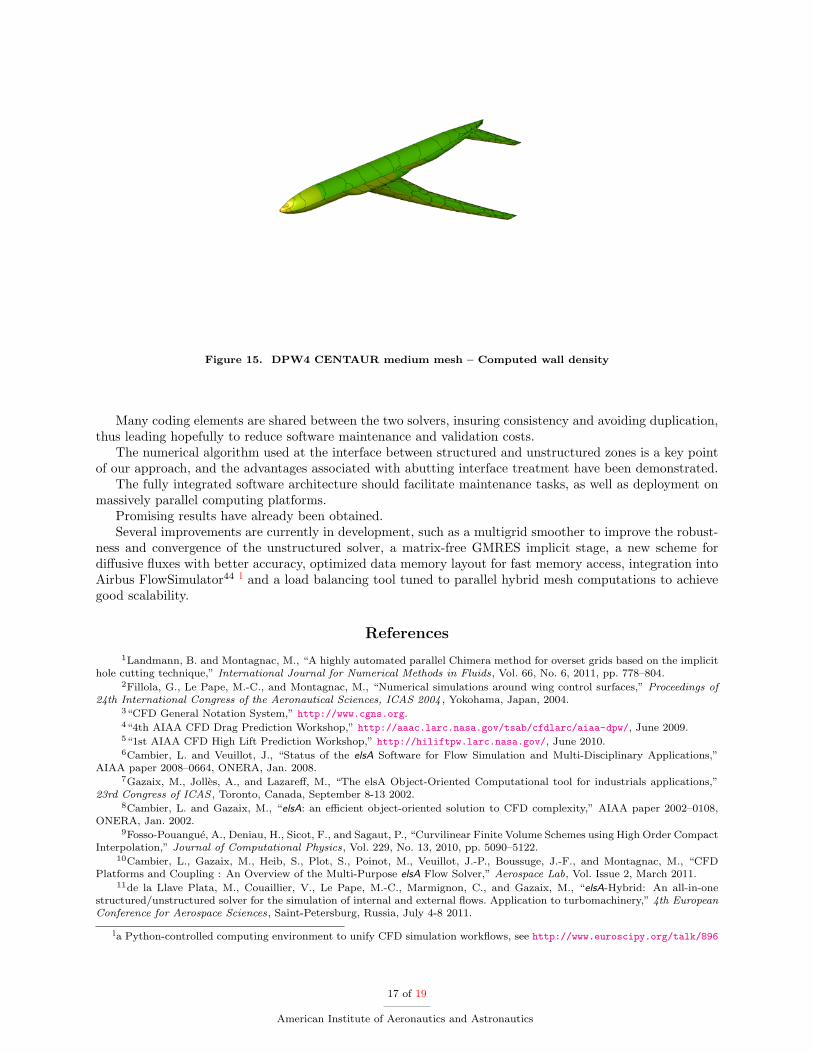
Figure 15. DPW4 CENTAUR medium mesh { Computed wall density
Many coding elements are shared between the two solvers, insuring consistency and avoiding duplication,thus leading hopefully to reduce software maintenance and validation costs.
The numerical algorithm used at the interface between structured and unstructured zones is a key pointof our approach, and the advantages associated with abutting interface treatment have been demonstrated.
The fully integrated software architecture should facilitate maintenance tasks, as well as deployment onmassively parallel computing platforms.
Promising results have already been obtained.Several improvements are currently in development, such as a multigrid smoother to improve the robust-
ness and convergence of the unstructured solver, a matrix-free GMRES implicit stage, a new scheme fordi�usive uxes with better accuracy, optimized data memory layout for fast memory access, integration intoAirbus FlowSimulator44 l and a load balancing tool tuned to parallel hybrid mesh computations to achievegood scalability.
References
1Landmann, B. and Montagnac, M., \A highly automated parallel Chimera method for overset grids based on the implicithole cutting technique," International Journal for Numerical Methods in Fluids, Vol. 66, No. 6, 2011, pp. 778{804.
2Fillola, G., Le Pape, M.-C., and Montagnac, M., \Numerical simulations around wing control surfaces," Proceedings of24th International Congress of the Aeronautical Sciences, ICAS 2004 , Yokohama, Japan, 2004.
3\CFD General Notation System," http://www.cgns.org.4\4th AIAA CFD Drag Prediction Workshop," http://aaac.larc.nasa.gov/tsab/cfdlarc/aiaa-dpw/, June 2009.5\1st AIAA CFD High Lift Prediction Workshop," http://hiliftpw.larc.nasa.gov/, June 2010.6Cambier, L. and Veuillot, J., \Status of the elsA Software for Flow Simulation and Multi-Disciplinary Applications,"
AIAA paper 2008{0664, ONERA, Jan. 2008.7Gazaix, M., Joll�es, A., and Lazare�, M., \The elsA Object-Oriented Computational tool for industrials applications,"
23rd Congress of ICAS , Toronto, Canada, September 8-13 2002.8Cambier, L. and Gazaix, M., \elsA: an e�cient object-oriented solution to CFD complexity," AIAA paper 2002{0108,
ONERA, Jan. 2002.9Fosso-Pouangu�e, A., Deniau, H., Sicot, F., and Sagaut, P., \Curvilinear Finite Volume Schemes using High Order Compact
Interpolation," Journal of Computational Physics, Vol. 229, No. 13, 2010, pp. 5090{5122.10Cambier, L., Gazaix, M., Heib, S., Plot, S., Poinot, M., Veuillot, J.-P., Boussuge, J.-F., and Montagnac, M., \CFD
Platforms and Coupling : An Overview of the Multi-Purpose elsA Flow Solver," Aerospace Lab, Vol. Issue 2, March 2011.11de la Llave Plata, M., Couaillier, V., Le Pape, M.-C., Marmignon, C., and Gazaix, M., \elsA-Hybrid: An all-in-one
structured/unstructured solver for the simulation of internal and external ows. Application to turbomachinery," 4th EuropeanConference for Aerospace Sciences, Saint-Petersburg, Russia, July 4-8 2011.
la Python-controlled computing environment to unify CFD simulation work ows, see http://www.euroscipy.org/talk/896
17 of 19
American Institute of Aeronautics and Astronautics

12Lefebvre, M., Couaillier, V., and Dubou�e, J., \Numerical methods on adaptive hybrid grids for the solution of Euler andNavier-Stokes equations," 4th ECCOMAS CFD Conference, Wiley, Athens, Greece, 1998.
13Soetrisno, M., Imlay, S. T., and Roberts, D. W., \A zonal implicit procedure for hybrid structured-unstructured grids,"32nd AIAA Aerospace Sciences Meeting and Exhibit , Reno, NV, Jan. 10-13 1994.
14Heinrich, R., \Implementation and Usage of Structured Algorithms within an Unstructured CFD Code," New Results inNumerical and Experimental Fluid Mechanics V , edited by H.-J. Rath, C. Holze, H.-J. Heinemann, R. Henke, and H. H�onlinger,No. 92 in Notes on Numerical Fluid Mechanics and Multidisciplinary Design, Springer, 2006, pp. 430{437.
15Cambier, L. and Kroll, N., \MIRACLE: a joint DLR/ONERA e�ort on harmonization and development of industrialand research aerodynamic computational environment," Aerospace Science and Technology, Vol. 12, No. 7, 2008, pp. 555{566.
16Schwamborn, D., Gerhold, T., and Heinrich, R., \The DLR TAU-CODE: Recent Applications in Research and Industry,"European Conference on Computational Fluid Dynamics, edited by P. Wesseling, E. O~nate, and P. P�eriaux, TU Delft, Egmondaan Zee, The Netherlands, September 5-8 2006.
17Yang, H., Nuernberger, D., and Kersken, H.-P., \Towards excellence in turbomachinery Computational Fluid Dynamics: ahybrid structured-unstructured Reynolds-Averaged Navier-Stokes solver," Journal of Turbomachinery, Vol. 128, 2006, pp. 390{402.
18Becker, K., Heitkamp, K., and K�ugeler, E., \Recent progress in a hybrid-grid CFD solver for turbomachinery ows,"Proceedings of ECCOMAS CFD , edited by J. C. F. Pereira and A. Sequeira, Lisbon, Portugal, June 14-17 2010.
19Katz, A., Jameson, A., and Wissink, A., \A Multi-solver Scheme for Viscous Flows Using Adaptive Cartesian Grids andMeshless Grid Communication," 47th AIAA Aerospace Sciences Meeting, Reno, NV, Jan. 5-8 2009, AIAA paper 2009-768.
20Sankaran, V., Wissink, A., Datta, A., Sitaraman, J., Jayaraman, B., Potsdam, M., Katz, A., Kamkar, S., Roget, B.,Mavriplis, D., Saberi, H., Chen, W., Johnson, W., and Strawn, R., \Overview of the Helios Version 2.0 Computational Platformfor Rotorcraft Simulations," 49th AIAA Aerospace Sciences Meeting and Exhibit , Orlando FL, Jan. 4-7 2011, AIAA paper 2011-1105.
21Sitaraman, J., Potsdam, M., Jayaraman, B., Datta, A., Wissink, A., Mavriplis, D., and Saberi, H., \Rotor LoadsPrediction Using Helios: A Multi-Solver Framework for Rotorcraft CFD/CSD Analysis," 49th AIAA Aerospace Sciences Meetingand Exhibit , Orlando FL, Jan. 4-7 2011, AIAA paper 2011-1123.
22Zheng, Y. and Liou, M.-S., \A novel approach of three-dimensional hybrid grid methodology: Part 1. Grid generation,"Computer Methods in Applied Mechanics and Engineering, Vol. 192, No. 37-38, 2003, pp. 4147{4171.
23Liou, M.-S. and Zheng, Y., \A novel approach of three-dimensional hybrid grid methodology: Part 2. Flow solution,"Computer Methods in Applied Mechanics and Engineering, Vol. 192, No. 37-38, 2003, pp. 4173{4193.
24Roe, P. L., \Approximate Riemann solvers, parameter vectors and di�erence schemes," Journal of Computational Physics,Vol. 43, No. 2, 1981, pp. 357{372.
25van Leer, B., \Towards the ultimate conservative di�erence scheme. V. A second-order sequel to Godunov’s method,"Journal of Computational Physics, Vol. 32, No. 1, 1979, pp. 101{136.
26Dervieux, A., \Steady Euler simulations using unstructured meshes," Partial di�erential Equations of hyperbolic typeand Applications, edited by J. Geymonat, chap. 2, World Scienti�c, 1987, pp. 34{112.
27Stou�et, B., P�eriaux, J., Fezoui, F., and Dervieux, A., \3-D Hypersonic Euler Numerical Simulations around SpaceVehicles using Adapted Finite Elements," 25th Aerospace Sciences Meeting and Exhibit , 1986, AIAA paper 86-0560.
28Fezoui, F. and Stou�et, B., \A class of implicit upwind schemes for Euler simulations with unstructured meshes," Journalof Computational Physics, Vol. 84, No. 1, 1989, pp. 174{206.
29Galle, M., \Unstructured viscous ow solution using adaptive hybrid grids," ICASE/LaRC workshop on adaptive gridmethods, NASA Langley Research Center, 1995.
30Crumpton, P., Moinier, P., and Giles, M., \An unstructured algorithm for high Reynolds number ows on highly stretchedgrids," Numerical Methods in Laminar and Turbulent Flow , edited by C. Taylor and J. T. Cross, Pineridge Press, 1997, pp.561{572.
31Fosso-Pouangu�e, A., \Mise en �uvre d’une approche non structur�ee dans elsA," Master thesis available on http://www.
cerfacs.fr/~cfdbib/repository/WN_CFD_07_88.pdf WN/CFD/07/88, CERFACS, September 2007.32Le Potier, C., \Sch�ema volumes �nis pour des op�erateurs de di�usion fortement anisotropes sur des maillages non
structur�es," C.R. Acad. Sci. Paris, Ser. I , Vol. 341, 2005, pp. 787{792.33Marmignon, C., Couaillier, V., and Courbet, B., \Solution Strategies for Integration of Semi-Discretized Flow Equations
in elsA and CEDRE," Onera Aerospace Lab, Vol. 2, 2011.34Lazare�, M., Peter, J., and Fourmaux, A., \Non-intrusive stochastic studies for external and internal ows using the elsA
software," Proceedings of ECCOMAS CFD , edited by J. C. F. Pereira and A. Sequeira, Lisbon, Portugal, June 14-17 2010.35Lazare�, M., \elsA User’s Reference Manual," http://elsa.onera.fr/ExternDocs/user/MU-98057.pdf, ONERA.36Puigt, G., Au�ray, V., and M�uller, J. D., \Discretisation of di�usive uxes on hybrid grids," Journal of Computational
Physics, Vol. 229, 2010, pp. 1425{1447.37Sutherland, I. and Hodgman, G., \Reentrant Polygon Clipping," Communications of the ACM , Vol. 17, No. 1, Jan. 1974,
pp. 32{42.38\METIS Graph Partioning, Mesh Partitioning, Matrix Reordering," http://www.cs.umn.edu/~metis.39Pellegrini, F., \SCOTCH : Software package and libraries for sequential and parallel graph partitioning," http://www.
labri.fr/perso/pelegrin/scotch/.40Gazaix, M. and Champagneux, S., \Recent results with elsA on multi-cores, DLR Symposium "CFD on FUTURE
Architectures", Braunschweig," http://tau.dlr.de/tau/usermeeting/2009/Symposium-talks/ONERA_Airbus.pdf, Oct. 2009.41Gazaix, M., Mazet, S., and Montagnac, M., \Large scale massively parallel computations with the block-structured elsA
CFD software," Parallel Computational Fluid Dynamics, Parallel Numerical Methods, Software Development and Applications,edited by D. Tromeur-Dervout, G. Brenner, D. R. Emerson, and J. Erhel, No. 74 in Lecture Notes in Computational Scienceand Engineering, Springer, Lyon (France), May 19-22 2008, pp. 111{117.
18 of 19
American Institute of Aeronautics and Astronautics

42Gourdain, N., Gicquel, L., Montagnac, M., Vermorel, O., Gazaix, M., Sta�elbach, G., Garc��a, M., Boussuge, J.-F., andPoinsot, T., \High performance parallel computing of ows in complex geometries - part 1: methods." Computational Scienceand Discovery, 2009.
43Hellstr�om, T. and Davidson, L., \Reynolds stress transport modelling of transonic ow around the RAE2822 airfoil,"AIAA paper 1994{0309, 1994.
44Meinel, M. and Einarsson, G., \The FlowSimulator framework for massively parallel CFD applications," Para 2010 {State of the Art in Scienti�c and Parallel Computing, University of Iceland, Reykjavik, June 6-9 2010.
19 of 19
American Institute of Aeronautics and Astronautics