development of microcontroller based vehicle alcohol …
TRANSCRIPT
International Journal of Scientific & Engineering Research Volume 12, Issue 6, June-2021 1215 ISSN 2229-5518
IJSER © 2021
http://www.ijser.org
Development Of Microcontroller Based Vehicle Alcohol Detection System
Aluko O. A., Ibiyomi M. A., Oyebiyi A.J.,
Department of Computer Engineering, The Federal Polytechnic, Ile-Oluji, Ondo State
Abstract
The vehicle accidents on most of high ways in Nigeria which had caused a lot people to lost their life and many sustained injuries
that made them to become handicapped has become worrisome over the years. In the recent times, roadworthy report presented
early in 2021 by Federal Road Safety Corp’ data and information unit recorded that 80% of the fatal accidents which claimed life
resulted from drunk driving. This problem necessitated the technical attention to alleviate this severity to bare minimum. The
project presents the development of a vehicle alcohol detection system using ATmega328P Microcontroller. The section include;
input section, control section and the output section, the input section consist of MQ-3 alcohol sensor which continuously monitor
the Blood Alcohol Content (BAC) to detect the existence of alcohol in the exhalation of a driver. The control unit consist of
ATmega328P microcontroller that interfacing and control the input response from MQ3 sensor and relay output through the LCD.
A DC motor of the vehicle was actively working and alerted the green indicator showing that the system is working perfectly and
there was no alcohol detected from the user. Upon detection of alcohol content from the driver, the red indicator switches on
automatically along with the buzzer sound a warning alarm for 60 seconds delay and display ‘drunk text’ on the display unit to
allow the driver to park before the ignition of vehicle is automatically switched off. The system was tested for continuity test and
evaluated for sensitivity, specificity and the accuracy. This system will reduce accident and loss of life caused by drunk driving
on our roads.
Keywords: BAC: Blood Alcohol Content, LCD: Liquid Crystal Display, DC: Direct Current
1. Introduction
Vehicle transportation is the most patronized means of transportation in commuting people and products from one location to
another. It is therefore expected to witness more road carnages than any other means of transportation such as rail, sea and air
transport, Deepa et al., (2015) Drink driving is one of the major causes of road accidents all over the world, Raiana et al.,(2019).
According to the Bureau of Transportation statistics, every 2 hours, three people are killed in alcohol related highway crash. A
major method for testing level of alcohol is the Blood Alcohol Content (BAC) test using breath analyzers at check points. Minonu
et al., (2010) and Toshiyuki et al., (2011) A 0.05% blood alcohol is enough to impair the sense of judgment when driving but mg/L
was introduced in the design, .Nirosha et al., (2012) and Pratissha et al., (2015) This method lacks credibility due to unavailability
of required manpower, compromise on the part of inspection officers and the cost of maintaining check points over a wide
geographical location. Even with this great technology, people still bypass some check points by passing other roads that lead to
their destination. For more secured and effective method to couple or reduce car accident based on the influence of drunk driving,
that is the main reason why Alcohol detection system is invented, Mohammed et al (2018). This device can detect the amount of
alcohol or sense the intake of alcohol through the help of the sensor (MQ-3 alcohol sensor) by senses the surrounding environment.
This sensed information is fed to an ATmega328 Microcontroller that processes the sensed data by comparison with a preset
threshold value. If alcohol is detected, the microcontroller takes effect on the buzzer and red LED. The red LED and buzzer will
be triggered, the system will be delayed for 60 seconds delay time for the driver to park and if the driver fails to park for that
interval, the vehicle will be turn off and will not move further.
IJSER
International Journal of Scientific & Engineering Research Volume 12, Issue 6, June-2021 1216 ISSN 2229-5518
IJSER © 2021
http://www.ijser.org
1.1 Statement of the problem
The high rate of road accident in most of our high-ways in Nigeria resulting from drunk-driving which has claimed many lives
and many sustained high injuries which has made them to be handicap in fact, Traffic survey shows that driver fatigue may be a
contributory factor in up to 20% and due to alcohol drinking it is about 50% of all road accidents. Radha and Patel (2019). Also,
data and information unit of Federal Road Safety Corps reported that more than 80% fatal accidents caused by this outrageous
manner of drunk-driving from vehicle users which has become worrisome and issue of concerned which need an urgent of
technological wise to reduce this problem to bare minimum.
2. Literature Review
Rajana et al. (2019). Developed a system to detect the alcohol content level of a driver titled “vehicle engine lock system for theft
and alcohol detection” its uses MQ3 sensors embedded in the steering the vehicle to content of alcohol taken by drivers. This
proposed explores the possibility at very first using technology. It’s also use to track the theft of vehicle if there is using fingerprint
recognition technique. It’s involved certain inherit error.
Rajesh et al. (2014) and Sudharsana et al. (2014). Came up with a Design which was titled, Drunk-Driver Detection and Alert
System (DDDAS) for Smart Vehicles. Their design is Based upon the recent smart gas sensing and integration of satellite and
cellular wireless communication technologies, their device has the ability to quickly sense the drunken state of the driver during
start-up/driving by estimating the equivalent breath alcohol concentration level corresponding to the legally permissible state’s
threshold blood alcohol concentration level. On detection of such situation, on-vehicle siren/audio alarm is activated to warn the
persons on road and vehicle control system is triggered to lock ignition or stop the fuel inflow to the vehicle. Additionally, ‘alert
SMS’ indicating drunk driver location, tracked by onboard GPS receiver, along with vehicle number is communicated remotely
to authorized (family members, traffic police) mobile user using GSM cellular network to take appropriate action. The system is
very effective and response time is very high. And the limitation to the design was that it uses GSM module which is network
dependence.
Absar et al. (2018) and Mohamad, (2013) also designed drunken driver detection and system with automated braking system. Its
uses eye blink detector to detect and the system will generate warning signal to alert the driver, GPS and GSM technology we
track the exact location of the accidental vehicle. When the driver didn’t response to the warning signal, an automated pneumatic
brake system is used to stop the vehicle within a distance.
Keerthan et al. (2018).and Dada et al (2017) Construct an alcohol sensor which is integrated with the directing wheel, titled
“Drunk Driving Detection using Car Ignition Locking” this framework is meant for making vehicle driving more secure than
previously and shield the mishap from happening due to the liquor utilization of the driver. This work proposed the detection of
alcohol utilizing alcohol sensor associated with arduino. Its uses arduino processor to check drunk driving and work a bolt on the
vehicle with embedded system which mixes both programming and equipment which can play out some particular capacities. It
has the ability to respond fast. Vaishnavi et al. (2014) Intelligent Alcohol Detection System for car using Microcontroller 16F877A
and MQ-2 sensor, it has ignition system which will produce spark plugs, it acts as ignition starter over the vehicle’s engine. It
involved certain inherit errors.
IJSER

International Journal of Scientific & Engineering Research Volume 12, Issue 6, June-2021 1217 ISSN 2229-5518
IJSER © 2021
http://www.ijser.org
3. Methodology
This chapter described the methodology used for the design of the hardware and software part, the main hardware part is the MQ-
3 sensor and how it interfaces with the microcontroller, display unit, and the DC motor, the methodology consideration and
specification of alcohol detection system and its functional components were recorded. The development stages and mode of
operation of the software application, simulation develop for the hardware were also reported
3.1 System Design Steps
The design steps involve in the development of the system will be aimed to operate off a 9volt power system. The system is
development of alcohol detection with at least one programmable integrated circuit in this case Atmega 328P microcontroller used
which is programmed using Arduino programmer. The microcontroller is program to receive signal from MQ-3 sensor once it
senses or detect the presence of the alcohol at above 2.9mg/L from the users of the vehicle, the alert unit will be activated by
indicating red light emitting diode and as well activate the alarm unit to sound a warning for 60seconds time delay to allow the
driver to pack the vehicle at a reasonable place before the ignition of the vehicle automatically off.
The system architecture consists of mechanical, electrical and electronics components which are integrated to complete the system
design as listed below;
i. ATmega 328P microcontroller v. MQ-3 sensor ix. Dc motor
ii. LCD vi. LED x. Battery (9volt)
iii. Crystal oscillator vii. Resistor (10kiloohms) xi. Capacitor(25pf)
iv. Voltage regulator (LM7805) viii. Buzzer
3.2 Hardware implementation of the design
Hardware of the system consist of ATmega328P, MQ-3 sensor, LED, LCD capacitor and other components with it design was
carried out on the manufacture Veroboard, mainly surface components in system programmer. The sensor unit comprises of an
integrated circuit module such as MQ-3 alcohol sensor which is place in from of the design. The integrated circuit is powered
using 9-volt dc power source. A signal is sent to the microcontroller each time alcohol is detected from the user of the vehicle and
necessary action are taken based on the program written on the microcontroller. The power source will be obtained from a 9-volt
battery. The microcontroller and other digital integrated circuit used 5-voltage for their operation and source a voltage regulator
will be used to regulate the 9-volt power supply to 5volt for the use by the circuit. The block diagram of the design is shown in
Figure 3.1
IJSER
International Journal of Scientific & Engineering Research Volume 12, Issue 6, June-2021 1218 ISSN 2229-5518
IJSER © 2021
http://www.ijser.org
ATMEGA 328P
MICROCONTROLLER
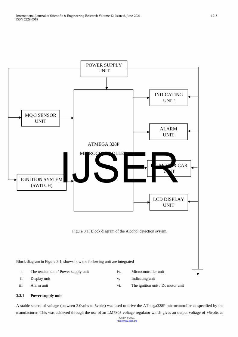
Figure 3.1: Block diagram of the Alcohol detection system.
Block diagram in Figure 3.1, shows how the following unit are integrated
i. The tension unit / Power supply unit iv. Microcontroller unit
ii. Display unit v, Indicating unit
iii. Alarm unit vi. The ignition unit / Dc motor unit
3.2.1 Power supply unit
A stable source of voltage (between 2.0volts to 5volts) was used to drive the ATmega328P microcontroller as specified by the
manufacturer. This was achieved through the use of an LM7805 voltage regulator which gives an output voltage of +5volts as
POWER SUPPLY
UNIT
IGNITION SYSTEM
(SWITCH)
MQ-3 SENSOR
UNIT
INDICATING
UNIT
ALARM
UNIT
DC-MOTOR CAR
UNIT
LCD DISPLAY
UNIT
IJSER

International Journal of Scientific & Engineering Research Volume 12, Issue 6, June-2021 1219 ISSN 2229-5518
IJSER © 2021
http://www.ijser.org
shown in Figure 3.2. This is made of rectifier diodes configured in a bridge arrangement as shown in fig below Figure 3.2. This is
necessary because integrated circuit as well as ATmega328P microcontroller can only run on D.C voltage.
U1 (7805) LM78xx voltage regulator specifications from datasheet:
o Input voltage range for 7805: Vin = 7.5v~20v
o Output voltage range for 7805: Vout= 4.75v~5.25v
The 9v battery is enough to supply the minimum input voltage for the system. C3 is transient capacitor and its rating as stipulated
in the 78xx voltage regulator’s datasheet as 0.1uf [reference]. These capacitors help for smoothening of the output from the voltage
regulators.
Current limiting resistor calculation:
R4 = Vout−VD
ID… … … … … … … … … … … … . . . . (3.1)
Vout = Output voltage of regulator
VD = Voltage drop across diode
ID = Forward current of LED
Light emitting diode (LED) characteristics:
Forward current of LED = 10mA and voltage drop = 2v [reference]. Therefore
R4 =5 − 2
10 x 10−3
R4 = 300Ω
Therefore, resistor value used is: 330Ω
The power supply section is very important for all electronic circuits. The system requires 5 volts dc. This voltage level will be
obtained from the 9v battery. The 9v is stepped down by to deliver a secondary output of 5V, 1 A. The 9v battery output is rectified
by a full-wave rectifier comprising diodes D1 through D2, filtered by capacitor C3 and C4 regulated by IC7805 (IC) Capacitor C3
bypasses the ripples present in the regulated supply. The power supply schematic is shown Figure3.2.
Figure 3.2: showing the interfacing Power Supply
3.2.2 ATmega328P Microcontroller unit
The Microcontroller unit as shown in Figure 3.3, can also be referred to the processing unit of the Alcohol detection system,
because it interfaces with all the components or units that makes the Alcohol detection system unit function. The microcontroller
has 14 pins in both side. ATmega328P microcontroller is developed by Arduino.cc. The board is equipped with sets of digital and
analog input/output (I/O) pins that may be interfaced to various expansion boards (shields) and other circuits. The board has 14
digital I/O pins (six capable of PWM output), 6 analog I/O pins, and is programmable with the Arduino IDE (Integrated
Development Environment), via a type B USB cable. And each pin is assigned a specific task to carry out.
IJSER

International Journal of Scientific & Engineering Research Volume 12, Issue 6, June-2021 1220 ISSN 2229-5518
IJSER © 2021
http://www.ijser.org
Figure 3.3: ATmega328P microcontroller unit of the alcohol detection system
3.2.3 Display unit
The display unit of the Alcohol detection system as shown in Figure 3.4, serves as part of the output unit of the design. 16x4
Character LCD Display was used for the display unit. 16x4 character-type liquid crystal display, is a kind of dot matrix module to
show letters, numbers, and characters and so on. It’s composed of 16row and 4colums dot matrix positions; each position can
display one character. There’s a dot pitch between two characters and a space between lines, thus separating characters and lines.
16x4 implies that its displays 4lines and 16characters. This LCD screen is equipped with an I2C adapter. The I2C is a type of
serial bus, which uses two bidirectional lines, called SDA (Serial Data Line) and SCL (Serial Clock Line). Both must be connected
via pulled-up resistors. The usage voltages are standard as 5V and 3.3V. The I2C adapter is already soldered onto the board,
because of this, the wiring is quite easy. Only four pins are required to hook up. VCC, GND, SDA and SCL. The LCD display
works with 5 Volts.
Figure 3.4: Display unit of the vehicle alcohol detection system.
3.2.4 Engine locking unit
The engine locking unit as shown in Figure 3.5, it was built by the concept of using a DC motor to demonstrate as the car engine.
The DC motor operate based on preset conditions; once the alcohol level goes above 2.9 mg/L the engine motor continuous to
move for 60seconds delay time for the driver to park, and if the if the driver fails to park for that interval, the engine motor will
move causing the vehicle to move further. The DC motor is connected too pin-9 on the microcontroller and it operate from 1.5volt
to 6volt.
3.2.5 Alcohol detection unit
IJSER

International Journal of Scientific & Engineering Research Volume 12, Issue 6, June-2021 1221 ISSN 2229-5518
IJSER © 2021
http://www.ijser.org
The alcohol sensor unit as shown in Figure 3.6, has four pins; test pin, vcc, dout and ground. The test pin is used to accept logic
signals of 0 or 1 by using logic state pin. Two LED was used for the design (Red and Green). This LED were used to show or
indicate when the system is working properly and when alcohol is detected. The green LED on automatically immediately the
system is powered on, indicating that the system is on and the vehicle is moving. The red LED turns on automatically when alcohol
is detected to indicate that alcohol is detected. in the simulation, when the logic state is 1 the led goes on to indicate that alcohol
is present and off indicate the condition of the presence.
Figure 3.5: Engine locking unit of the alcohol detection system
Figure 3.6: Alcohol detection unit of the alcohol detection system
3.2.6 Indicating unit
The Indicating unit as show in Figure 3.7, helped to indicate the condition of the system. Two LED were used for the design (Red
and Green). This LED were used to show or indicate when the system is working properly and when alcohol is detected. The green
LED on automatically immediately the system is powered on, indicating that the system is on and the vehicle is moving. The red
LED turns on automatically when alcohol is detected to indicate that alcohol is detected. in the simulation, when the logic state is
1 the led goes on to indicate that alcohol is present and off indicate the condition of .
IJSER

International Journal of Scientific & Engineering Research Volume 12, Issue 6, June-2021 1222 ISSN 2229-5518
IJSER © 2021
http://www.ijser.org
Figure 3.7: Indicating unit of the alcohol detection system
3.2.7 Alarm Unit
The alarm unit as shown in Figure 3.8, uses a buzzer which sounds and indicate that alcohol is detected. The buzzer used belongs
to the PS series. The PS series are high-performance buzzers that employ Uni-morph piezoelectric elements and are designed for
easy incorporation into various circuits. They have very low power consumption in comparison to electromagnetic units. It has a
voltage requirement of 2V and is connected to pin 16 of the microcontroller. The purpose of the buzzer was to create awareness
to passengers whenever alcohol is detected.
Figure 3.8: Alarming unit of the alcohol detection syst
3.2.8 Engine locking unit
The engine locking unit as shown in Figure 3.9, it was built by the concept of using a DC motor to demonstrate as the car engine.
The DC motor operate based on preset conditions; once the alcohol level goes above 2.9 mg/L the engine motor continuous to
move for 60seconds delay time for the driver to park, and if the if the driver fails to park for that interval, the engine motor will
move causing the vehicle to move further. The DC motor is connected too pin-16 on the microcontroller and it operate from 1.5volt
to 6volt.
Figure 3.10: Ignition unit of the alcohol detection system
3.3 Design Analysis
The circuit diagram as shown in Figure 3.11, was designed using Proteus professional, version 7.9 software installed on PC which
is running on a windows 10 Operating system. The Proteus circuit diagram design and the diagrammatical representation are shown
in Fig. 3.10, The Vehicle alcohol detection system is powered on using 9volt DC battery, the 9volt DC battery is further stepdown
to 5volt required by the microcontroller, sensor, display and indicating unit. The ATmega328P microcontroller has already been
designed to operate without the use of transformer. While other components like DC motor require 1.5V and the LEDs need 2V.
The Arduino board is designed locally in such a way that the microcontroller is able to interact with all the units present in the
design of the vehicle alcohol detector system. In designing the local Arduino board, Veroboard was used and the component listed
in the system design were all used. Some pins configuration was change pins such as; SDA to 27, SCL to 28, RX to 3, AO to 23,
13 to 19, which is the LED connector, 9 to 15 which is the buzzer connector and 10 to 18 which is the motor connector, all the
IJSER

International Journal of Scientific & Engineering Research Volume 12, Issue 6, June-2021 1223 ISSN 2229-5518
IJSER © 2021
http://www.ijser.org
component were connected and they were able to interact with each other. The connection start from the source which is the DC
battery to the LM8075 voltage regulator which regulated the 9volt Dc battery to 5volt, and it was connected to pin 7 and 5 on the
microcontroller were other component takes instruction for execution. A 10KΩ resistor was used and connected to pin1 through
pin 7 of microcontroller on port A. The two capacitors of each 22pF were connected to 12MHz crystal oscillator in parallel
connection with the microcontroller on pin 9 through pin10 respectively. This was to synchronize the operation of the
microcontroller and other electronics on the board. In the design, one busser was used which was connected to pin15 and other
pins was grounded, the dc motor to pin pin16 and the LED pin was connected to pin19, after which they were also grounded. The
physical implementation of the design was carried out on the manufactured breadboards using mainly surface mounted
components. The component was then soldered into the respective component slots using a 30W soldering iron.
Figure 3.11: Complete Circuit diagram of the Alcohol detection system
3.3.1 Operation of Alcohol detection system using ATmega328P microprocessor
In the designed system, when the system is power on through the switch, signal will be send to the ATmega328P microcontroller
immediately the LCD will display ‘Digital Alcohol Analyzer’ for few seconds before it started to analyze the Blood Alcohol
Contents (BAC). The value for the Blood Alcohol Contents (BAC), usually fluctuate because of gas particle in air. During this
period or interval, the green LED indicator will be on along with the dc motor and the LCD will display ‘Normal’ text. The green
LED is used to indicate that the system is working properly and the is dc motor moving. The buzzer and the red LED will remain
idle during this process, which implies that no alcohol is detected. Immediately the MQ-3 alcohol sensor senses the present of
alcohol, and the concentration of the Blood Alcohol Contents (BAC) value is above 2.9 Mg/L, the sensor will send a signal to the
ATmeha328P microcontroller and the Buzzer will be activated along with the RED light. At this point, the green LED will be on
and the dc motor will still be moving at its normal speed but, The LCD will display ‘Drunk’ text. This process helps to notify the
driver of the vehicle that alcohol has being detected and the process will last for 60seconds delay of time for the driver to park.
And if the driver fails to park for this interval of time, the dc motor will automatically stop moving, green LED will be off and the
buzzer will be deactivated to stop alarming. The red LED will remain on and the LCD will still display drunk.
3.4 Software Design approach
IJSER

International Journal of Scientific & Engineering Research Volume 12, Issue 6, June-2021 1224 ISSN 2229-5518
IJSER © 2021
http://www.ijser.org
The software design for this project was implemented using a C compiler for ATmega microchip. This compiler consists of an
optimized C compiler program as well as improved functions for many microcontroller operations. The flow chart on Figure 3.10:
shows the implementation of the algorithm used in the programming of theATmega328P microcontroller. The program on starting
initializes the microcontroller unit on boot up.
3.4.1 Loading of Code to ATmega328P Microcontroller
The code loading process of microcontroller is called dumping. The microcontrollers understand only the machine level language,
which contains ‘0 or 1s’. There is need to load the Hex code into the microcontroller. There are various programmer software
available in the market for loading the code to the microcontroller. Here, ‘Arduino’ programmer software was used to dump the
code to the PIC microcontroller as shown in Figure 3.12. The programmer kit comes with the hardware kit along with the software.
The ATmega328P microcontroller placed in the hardware kit, which comes with the socket. Here are the steps to load the code
onto the microcontroller.
i. Interface the hardware (programmer kit) to the computer through a serial cable.
ii. Place the microcontroller in the socket of the hardware kit. Press the lock button to ensure the microcontroller is
connected to the board.
iii. Open the software installed in the computer. This shows the menu bar with file, functions, open, save and setting
options.
iv. Select the ‘Open’ option from the drop-down menu and select the ‘Load file’.
v. Click on the ‘Load’ button so that the hex file is loaded into the microcontroller.
Figure 3.12: Code Dumping Device
4. Results
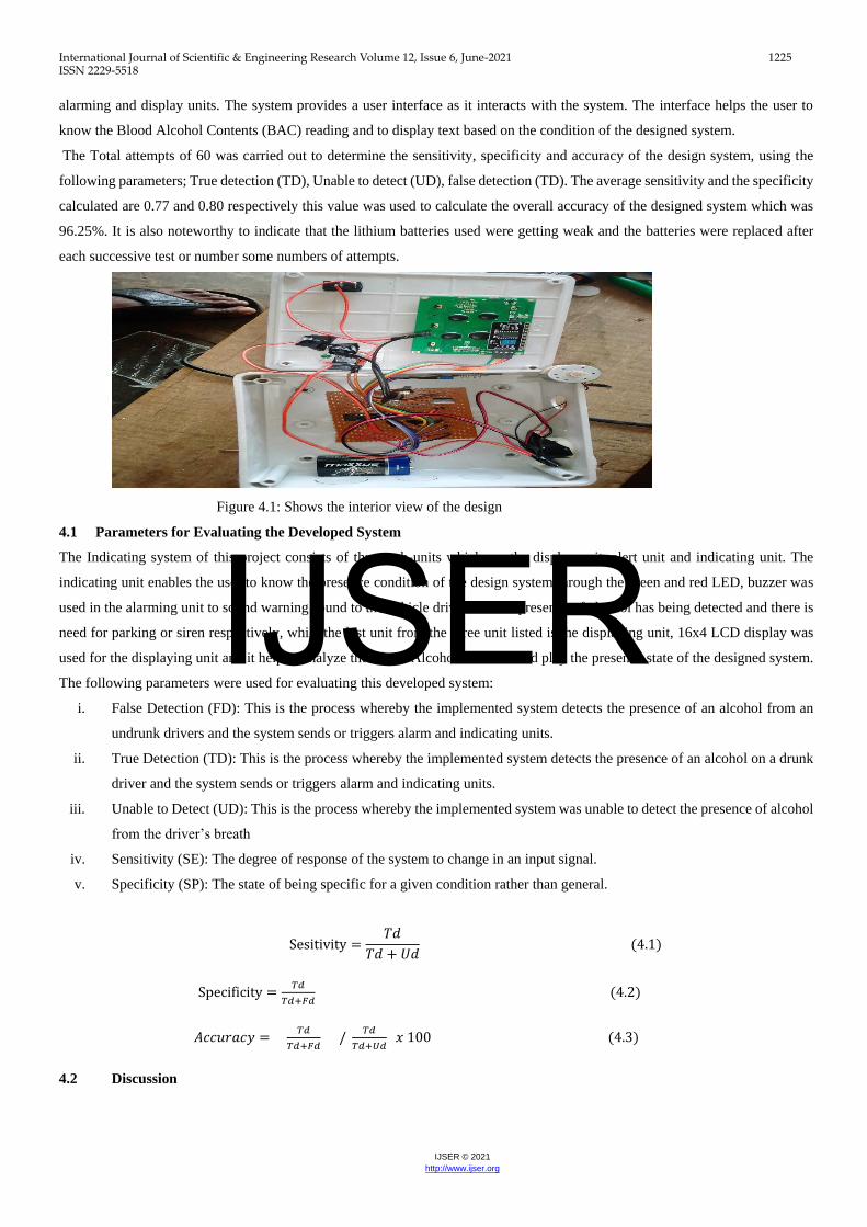
The result of simulation ensures that the circuit worked properly. The practical implementation of simulated circuit has been
presented in Figure 4.1. In this circuit diagram ATmega328P microcontrollers was the main components used for controlling other
devices (MQ-3 sensor, LCD, LED, Buzzer, Dc motor). Among the controlling devices, MQ-3 sensor was used as a sensor for
determining the present status of the system.
MQ-3 sensor was used as an input device for the designed system in order to sense the presence of alcohol from drivers breath, it
sends signal to the ATmeha328P microcontroller if the alcohol contents sensed is above 2.9Mg/L. Immediately the signal is sent
to the ATmega328P controller, the whole process automatically kick starts, the overall working of the system is controlled by the
Switch. The LEDs (Green and Red), gives the feedback of the processes taking place inside the system. Delay time was set into
the system in order allow the driver to park. The delay time is the important part of the designed system because, if the delay times
was not introduced, the invention of the project will not have help the society and the present generation to reduce accident due to
drunk driving. The connectivity is provided based on the ATmega328P Microcontroller and then communicates with LED,
IJSER
International Journal of Scientific & Engineering Research Volume 12, Issue 6, June-2021 1225 ISSN 2229-5518
IJSER © 2021
http://www.ijser.org
alarming and display units. The system provides a user interface as it interacts with the system. The interface helps the user to
know the Blood Alcohol Contents (BAC) reading and to display text based on the condition of the designed system.
The Total attempts of 60 was carried out to determine the sensitivity, specificity and accuracy of the design system, using the
following parameters; True detection (TD), Unable to detect (UD), false detection (TD). The average sensitivity and the specificity
calculated are 0.77 and 0.80 respectively this value was used to calculate the overall accuracy of the designed system which was
96.25%. It is also noteworthy to indicate that the lithium batteries used were getting weak and the batteries were replaced after
each successive test or number some numbers of attempts.
Figure 4.1: Shows the interior view of the design
4.1 Parameters for Evaluating the Developed System
The Indicating system of this project consists of three sub-units which are the display unit, alert unit and indicating unit. The
indicating unit enables the user to know the presence condition of the design system through the green and red LED, buzzer was
used in the alarming unit to sound warning sound to the vehicle driver that the presence of alcohol has being detected and there is
need for parking or siren respectively, while the last unit from the three unit listed is the displaying unit, 16x4 LCD display was
used for the displaying unit and it help to analyze the Blood Alcohol Contents and play the presence state of the designed system.
The following parameters were used for evaluating this developed system:
i. False Detection (FD): This is the process whereby the implemented system detects the presence of an alcohol from an
undrunk drivers and the system sends or triggers alarm and indicating units.
ii. True Detection (TD): This is the process whereby the implemented system detects the presence of an alcohol on a drunk
driver and the system sends or triggers alarm and indicating units.
iii. Unable to Detect (UD): This is the process whereby the implemented system was unable to detect the presence of alcohol
from the driver’s breath
iv. Sensitivity (SE): The degree of response of the system to change in an input signal.
v. Specificity (SP): The state of being specific for a given condition rather than general.
Sesitivity =𝑇𝑑
𝑇𝑑 + 𝑈𝑑 (4.1)
Specificity =𝑇𝑑
𝑇𝑑+𝐹𝑑 (4.2)
𝐴𝑐𝑐𝑢𝑟𝑎𝑐𝑦 = 𝑇𝑑
𝑇𝑑+𝐹𝑑 /
𝑇𝑑
𝑇𝑑+𝑈𝑑 𝑥 100 (4.3)
4.2 Discussion
IJSER

International Journal of Scientific & Engineering Research Volume 12, Issue 6, June-2021 1226 ISSN 2229-5518
IJSER © 2021
http://www.ijser.org
The prototype was designed and implemented. The results obtained from the combination of various alcohol detection system
components and corresponding constructions are evaluated and some observations were made during the different stages of testing.
Some distances were taken so as to ascertain the workability of the alcohol detection system.
The percentage error reflected was due to internal frictions within the alcohol detection system mechanism. The Specificity (SE)
of the developed system was 0.80 (80%). This implies the ability of the implemented alcohol detection system correctly detect the
presence of alcohol and trigger alarm, display and indicating units. The Sensitivity of the implemented alcohol detection system
was 0.77 (77%). This indicates that the implemented alcohol detection system was able to correctly detect the presence of alcohol
and trigger alarm, display and indicating units to notify the vehicle driver. Nevertheless, the Recognition Accuracy of the designed
system was 96.25%
5. Conclusion
In conclusion, the construction of a Vehicle Alcohol Detection System using ATmega328P microcontroller gives good response
and accurate results as expected. This study designed and implemented an Alcohol Detection System Usingatmega328P to reduce
accident due to drunk driving. The Microcontroller ATmega328p was programmed with C language and the sensitivity of the
designed devices was accurate compared to the works and developments.
5.1 Recommendation
This future implication or scope of the research, is very great considering the fact that it alleviates accident and save lives. This
system can be advanced and integrated as a wearable device which can be mandatory for every driver to wear while driving as
driving jacket especially on the highways road.
IJSER

International Journal of Scientific & Engineering Research Volume 12, Issue 6, June-2021 1227 ISSN 2229-5518
IJSER © 2021
http://www.ijser.org
REFERENCES
Absar, A.M., A1-Ibrahinsha, M.M., Rafic, S.M, Mohanavel, V., & Janarthana, P. (2019). Drunken driver detection and alarming
system with automated braking system. International journal of engineering science and computing, 8(3) 16354-
16362.
Dada, E., Hamit, I., Adebimpe, Adekunle L., & Ajibuwa, E. (2017). Alcohol Detection of Drunk Drivers with Automatic Car
Engine Locking System. Nova Journal of Engineering and Applied Sciences, 6(1) 1-15.
Deepa, KB., Chaitra, M., Ankit, Kumar., Sreedhar, VS., & Prashanth, Kumar. (2015). Accident Prevention by Eye Blinking
Sensor and Alcohol Detector. International Journal of Engineering Research, 4(7), 351-354.
Keerthana. R. K., & DrBharathi. N. (2018). Drunk Driving Detection using Car Ignition Locking. International Journal of Pure
and Applied Mathematics. 8(7), 2997-3008.
Kulkarni, P., Ravina, W., Shruti, S., & Gaurav, A. (2014). Alcohol Detection and Automatic Drunken Drive Avoiding System.
International Journal of Engineering Research and Applications, 4(4), 21-24.
Mohammed, A. A., Mohammed, A., Mohammed, R.S., & Mohanavel. V. (2018). Drunk Driving Detection & Alarming System
with Automated Braking System. International Journal of Engineering Science and Computing, 8(3). 1-2.
Mohamad, M., & Mohd, H. (2013). Vehicle Accident Prevention System Embedded with Alcohol Detector.
International Journal of Review in Electronic Communication Engineering (IJRECE), 1(4), 100-102.
Minoru, S., Daisuke, S., Ayako, N., Yukilo, I., & Massahi, K. (2010). Simultaneous detection of breath and alcohol using
breath-alcohol sensor for preventive of drunk driving. IEICE Electronics Express, 7(6), 467-472.
Nirosha, K., Priyanka, C., & Anil, K. (2017). Alcohol Detection in Vehicles. International Research Journal of Engineering and
Technology (IRJET), 4(4). 2025-2030.
Pratiksha, B., Karan, D., Archita, K., & Vijayalakshmi, B. (2015). Alcohol Detection and
Vehicle Controlling. International Journal of Engineering Trends and Applications
(IJETA,) 2(2), 90-97.
Rajana, P., Mukesh, R., Kumar, A., Sujith, N.N.S.S., & Sathyasai, C. H. (2019). Vehicle Engine Lock System for Theft and
Alcohol Detection. International Journal of Recent Technology and Engineering, 7(5). 363-367.
Radha, R., & Patel, A. (2019). Real time Driver Drowsiness Alert and Alcohol Intoxication Detection with Vehicle Control.
International Journal of Scientific Research and Review, 7(5), 792-802.
Rajesh, K., Roop, P., Raj, K., & Bhagirath, S. (2014). Drunk-Driver Detection and Alert System (DDDAS) for Smart Vehicles.
American Journal of Traffic and Transportation Engineering, 2(4), 45-58.
Sudharsana, V., Vineed, T., Merin, M., Simna, S., & Muhammed, S. (2014). Alcohol Detection Using Smart Helmet System.
International Journal of Emerging Technology in Computer Science & Electronics (IJETCSE), 8(1), 190-195.
IJSER

International Journal of Scientific & Engineering Research Volume 12, Issue 6, June-2021 1228 ISSN 2229-5518
IJSER © 2021
http://www.ijser.org
Toshiyuki, T., Kiyomi, S., Atsushi, N., Toshihiro, W., Shohei, Y., & Bunji, Atsumi. (2011). Development of a New Breath
Alcohol Detector without Mouthpiece Prevent drunk Driving, R&D Review of Toyotal CRDL, 42(3), 47-51
Vaishnavi, M., Umadevi, V., Vinothini, M., Bhaskar, Rao., & Pavithra, S. (2014). Intelligent Alcohol Detection System for Car.
International Journal of Scientific & Engineering Research., 5(11), 598-603.
Vijay, S., Hardik, A., & Dhrumil, P. (2015). Alcohol Detection and Accident Prevention of Vehicle. International Journal of
Innovative and Emerging Research in Engineering. 2(3), 55-59.
Vijay, J., Saritha, B., Priyadharshini, B., Deepeka, S., & Laxmi, R. (2011). Drunken Drive Protection System. International
Journal of Scientific & Engineering Research, 2(12), 1-4.
Vijay, N., Kukre, O., Omkar, G., Pranav, E., & Manav, B. (2015). IJARIIE, 4(2), 771-771
IJSER