development of model for the simulation of an … fileremoved by the deaerator (mechanical...
TRANSCRIPT

European Journal of Engineering and Technology Vol. 7 No. 4, 2019 ISSN 2056-5860
Progressive Academic Publishing, UK Page 94 www.idpublications.org
DEVELOPMENT OF MODEL FOR THE SIMULATION OF AN
INDUSTRIAL DEAERATOR FOR BOILER FEED WATER
PRODUCTION
Dr. Jackson Akpa
Rivers State University
NIGERIA
Dr. Dagde K.K
Rivers State University
NIGERIA
Believe Moses
Rivers State University
NIGERIA
ABSTRACT
This research considers a mathematical model development for deaerator performance
simulation considering current operating parameters and monitoring trend of performance
based on the flow-regimes and operating conditions. This research is aimed at generally
minimizing the cost of boiler feed water (BFW) production by reducing energy losses and
achieving ≤1ppm oxygen concentration in boiler feed water with minimum chemical
deaeration requirement. To achieve this, Mass & Energy balance was done on the deaerator
under study, models were also developed to predict the actual steam and venting rate required
for appropriate mechanical deaeration, and the oxygen continuity equation was adopted and
solved to estimate oxygen concentration in feed water from deaerator. The outcome of this
research showed that current deaerator performance was <40% and deaerator excess steam
/venting rate losses could be minimized to mitigate artificial rain around deaerator and still
achieve minimum oxygen concentration in deaerator outlet by maintaining balanced heat load
to the deaerator during operation. Owing to deaerator design specification and result of
simulation, case study deaerator should be operated at a temperature ≥108°C as this after
simulation corresponds to an oxygen concentration of ≤1.33ppm at the deaerator outlet, a
control valve should be utilized at deaerator vent to regulate venting based on operating
conditions. Further studies should consider studying how conductivity/other properties of
water affect deaeration.
Keywords: Deaeration, Eliminox, Low pressure steam, Return Condensate, Corrosion.
INTRODUCTION
Deaeration simply involves removal of entrained or dissolved gases from water which will
serve as feed to boilers or for use in other process units. The gases of concern in boiler operation
are mainly oxygen and carbon dioxide which as a result of natural causes are present in water.
The presence of Oxygen and carbon dioxide in untreated water act as corrosion causatives in
boilers as well as steam plant materials. The rate of the corrosion is directly proportional to the
quantity of the gas present in the feed water, this corrosion action is further accelerated in high
temperature conditions which in practice would be experienced in boilers during steam
generation. Primarily, the function of deaeration is mainly to reduce the concentration of both
dissolved oxygen and carbon dioxide in water to minimum levels such that its potential to cause
corrosion to boiler materials such as alloy steel and carbon steel is totally eliminated at
prevailing boiler operating conditions (temperature and pressure) as well as other transport
equipments (pump parts, and pipes) (Deaerator White Paper for use in boilers;2011, pg 1-7).
Deaerators are mechanical devices which remove dissolved gases from boiler feed water.
Deaeration process helps protect steam system from the effects of corrosive gases. It achieves

European Journal of Engineering and Technology Vol. 7 No. 4, 2019 ISSN 2056-5860
Progressive Academic Publishing, UK Page 95 www.idpublications.org
this by reducing the concentration of dissolved oxygen and carbon dioxide to levels where
corrosion effect is minimized. Generally, dissolved oxygen level of 5ppm or even lower is
required to prevent corrosion in most high-pressure boilers. Although oxygen concentrations
of up to 43 ppb can be tolerated in low-pressure boilers, but equipment life is extended at very
little or no extra cost by simply limiting the oxygen concentration to 5 ppm or even trace as
required by some industries. It is worthy of note that dissolved carbon dioxide is completely
removed by the deaerator (mechanical deaeration).Deaerators can be used in any chemical
industry or in power plants where boilers are employed for steam production from boiler feed
water (B.F.W). Deaerator serves the purpose of removal of unwanted dissolved gases and
dissolved oxygen from the boiler feed water before entering into boilers. Most deaerators are
designed such that dissolved oxygen content in the outlet water (discharge) is about 7 ppm by
wt% (http://www.chemicalengineeringsite.com/deaerators-purpose-principle).
At elevated temperature, boiler parts such as feed water piping, pumps, and economizers are
subject to severe oxygen (O2) corrosion attacks even though a minute level of oxygen is present
in the water, There is a constant financial challenge of not only changing corroded boiler parts,
but there is also the physical risk of boiler blow-out which could occur when boiler vessel has
under gone scaling and corrosion.
Generally Iron or steel are the major materials used in designing boilers, boiler feed water
piping, as well as other downstream equipments. Corrosion of these materials is often caused
by three key factors namely: Temperature, dissolved oxygen concentration and pH value which
in turn influence the aggressiveness of boiler corrosion. The greater the temperature, and the
lower the pH value the higher the aggressiveness of the feed water in causing corrosion. The
amount of dissolved oxygen in feed water is a huge factor in determining the amount of
corrosion that will occur.
Furthermore, carbon dioxide can combine with condensate to form carbonic acid which can
massively corrode boiler feed water & steam handling equipments.(Connor S, (2015).)
CO2 + H2O H2CO3 (Carbonic Acid)
Corrosion rate as a result of dissolved O2 and CO2 doubles steadily as temperature Increases.
Iron begins to dissolve when in contact with water
Fe + 2H2O Fe (OH)2 + 2H+
Iron Water Ferrous Hydrogen
Hydroxide
Increased presence of O2 will cause the ferrous hydroxide to form ferric hydroxide (Rust)
4Fe (OH)2 + O2 + H2O 4Fe(OH)3 (Ferric Hydroxide [RUST])
These amongst many further emphasize the importance and relevance of a deaerator in any
efficient boiler system. In to maintain an effective boiler system the deaerator performance
must be at optimum at all times both for existing and newly installed deaerator units.
This research aims to develop a mathematical model for the simulation of an existing industrial
deaerator performance to achieve desired oxygen concentration in feed water with minimal
chemical injection and reduce energy expended to achieve desired mechanical deaeration.
To achieve these, the following was carried out;
• Mass/Energy balance on the deaerator.
• Use model developed to estimate the actual venting rate and low pressure steam
requirement to deaerator corresponding to return condensate flow conditions.

European Journal of Engineering and Technology Vol. 7 No. 4, 2019 ISSN 2056-5860
Progressive Academic Publishing, UK Page 96 www.idpublications.org
• Outline current deaerator operating parameters and estimate efficiency of deaeration.
• To reduce energy losses by developing a balance between the steam required to achieve
optimum deaeration and return condensate to deaerator.
DEAERATOR TECHNOLOGY
During deaeration, feed water is steadily heated to saturation temperature while maintaining a
minimum vent and pressure drop. This action ensures optimum thermal operational efficiency.
Deaeration is carried out by sprinkling the feed water over multiple tray layers designed to
enable large contact surface between the liquid droplets and steam used for deaeration. The
steam used for scrubbing is fed from the bottom of the deaerator. When the steam contacts the
boiler feed water, it gradually brings it to saturation temperature and the dissolved gases in the
feed water are released through the vent valve. Treated water drops to the storage vessel
beneath the deaerator (Babcock et. al, 2005).
Since the solubility of oxygen in water is reduced through heating, steam causes the feed water
to give up the dissolved oxygen more readily. Steam is and still remains a highly efficient
medium for heating and breaking up the water droplets via scrubbing, Often a very small
quantity of steam is vented to the atmosphere during deaeration. Most of the steams used in
heating and scrubbing are condensed and they become part of the deaerated water and return
to the storage of the deaerator. The design of a proper deaerator system largely depends on the
quantity of gases to be removed and the desired oxygen concentration after deaeration. This
depends on the ratio of boiler feed water to return condensate and the deaerator operating
pressure. Deaerators require low pressure (LP) steam to heat the water to its full saturation
temperature which corresponds to the steam pressure in the deaerator to drive away dissolved
gases. Steam flow may either be parallel, counter or cross to the flow of water. Deaerators
consist of the deaeration section, a storage tank, and a vent opening. Inside the deaeration
section, steam bubbles through the water, heating and agitating it. Non-condensable gases
associated with the feed water and a portion of steam are released through the deaerator vent.
Steam to the deaerator enables the stripping action and heats up the mixture of boiler feed water
and return condensate to its saturation temperature. Often, a portion of steam will condense,
but a fraction (5% - 14%) must be continuously vented to accommodate the stripping
requirement of the deaerator. Design practice usually is to obtain the steam required for heating
and ensure the flow is enough for stripping. Where rate of return condensate is high (>80%)
with the pressure of condensate high when compared to the deaerator pressure, then a little
portion of steam would be required for heating. When properly installed and operated,
deaerators are designed to provide continuous boiler operation, even with significant load
changes without any form of involvement from the operator. Variation in temperature, level of
water and pressure in a deaerator can cause not only “Water Hammer”, but malfunction of
auxiliary-equipment and boiler also operational anomalies. As a result deaerators are usually
well instrumented (Evaluating deaerator operation -www.hpac.com/building-controls).
Principle of Deaerators
Deaerators normally operate based on the principles stated below;
Henrys Law
Solubility of a gas in a liquid is directly proportional to the partial pressure. Hence if the partial
pressure of the entrained gas is decreased by adding steam to the deaerator, its solubility will
decrease and the gas is driven away from the water.

European Journal of Engineering and Technology Vol. 7 No. 4, 2019 ISSN 2056-5860
Progressive Academic Publishing, UK Page 97 www.idpublications.org
Inverse Solubility of Water
When temperature of water is increased, dissolved oxygen in the feed water decreases. Hence
when the temperature of water is increased by adding low pressure steam into the deaerator,
solubility of dissolved gas is decreased and the gases are driven from water.
(http://www.chemicalengineeringsite.com/deaerators-purpose-principle).
Deaeration Efficiency and Principles:
(1) Feed water should be atomized into droplets to increase the area available for both steam
and water to contact, as this aids the removal of dissolved gases.
(2) The water should be heated to its saturation temperature in other to achieve a 'zero' gas
solubility environment.
(3) Major contact must be established between water and steam in other to enable gases
be scrubbed out within a lesser duration.
(4) Gases removed by deaeration should be sufficiently diluted with steam in other to establish
minimum partial pressure above the surface of water.
(5) Gases removed from feed water should be vented. I other to maintain operational efficiency,
vent steam losses should be maintained at a minimum rate.(American boiler manufacturers
association.(2011)).
Deaeration Methods
Water deaeration is achieved by either chemical or mechanical methods.
For chemical deaeration stage, different chemicals can be adopted to react with the oxygen in
water. The products of this reaction are not harmful to the boiler systems. There exist various
chemicals which can be introduced into water to also react with the carbon dioxide and change
it into a neutral form.
Basically, mechanical deaeration removes non-condensables, instead of transforming the
carbon dioxide and oxygen in the water supply. Mechanical deaeration reverses the mechanism
by which the gases initially go into solution with water.
Theory of Mechanical Oxygen Removal
The solubility of oxygen is proportional to the partial pressure acting when it comes in contacts
with the water (Henry’s Law). The atmosphere (21% oxygen) is the source of oxygen in water,
At a temperature 15ºC, water in will absorb up to 10 ppm of oxygen when exposed to the
atmosphere.
As earlier stated, solubility of oxygen in water will decrease as the temperature of water rises.
When this occurs, the amount of water vapor in the atmosphere above the water will also
increase. This means that lesser Oxygen can be held by water when its temperature increases,
the amount of oxygen approaches ‘zero’ as the water reaches its saturation temperature.
Based these physical attributes, oxygen can be dislodged from water by raising the temperature
and reducing the concentration of O2 in the atmosphere above the water.(American boiler
manufacturers association.(2011)).
Mechanical deaeration of feed water is mainly achieved by scrubbing the feed water using low
pressure steam of 3.5 kg/cm2.g to remove dissolved oxygen/carbon dioxide. Typically,
mechanical deaeration occurs in the deaerating section of deaerators. By heating action of
steam the dissolved gases in the water is released into the steam and forced out through the
vent. Venting is allowed to take place to ensure complete deaeration. The efficiency of
deaeration (mechanical) depends on the temperature and pressure of the steam used for

European Journal of Engineering and Technology Vol. 7 No. 4, 2019 ISSN 2056-5860
Progressive Academic Publishing, UK Page 98 www.idpublications.org
deaeration and the type of deaerator. A steam plume is advised to be maintained at all times to
ensure complete venting. Although complete removal of CO2 can be achieved by mechanical
deaeration, Oxygen can still exist to about 10-7ppm, depending on deaerator efficiency. Hence
chemical deaeration is carried out to achieve complete removal of oxygen.
Chemical Deaeration:
This method of deaeration is basically carried out in the storage section of the deaerator which
holds the deaerated water. In this process, an oxygen scavenger is used to achieve complete
removal of oxygen. Eliminox or hydrazine (N2H4) is injected into the storage section of the
deaerator to allow the Oxygen scavenger maximum time to react with the oxygen before it
causes any damage. Eliminox reacts with the remaining trace of oxygen in water to form
Ammonia(NH3),Water (H2O) and Nitrogen (N2) (at elevated temperatures) with nitrogen been
vented out.
There exist different chemical species which react rapidly with available oxygen. They are
often referred to as oxygen scavengers. These scavengers have 2-categories namely;
(i) Weak bases (hydrazine and its alternatives) (2) Sulfites (IC Controls Limited (2015))
Deaerator Steam Consumption
Deaerator steam consumption is equivalent to the sum of steam needed to raise the temperature
of deaerator feed water to its saturation temperature, and the amount vented with the non-
condensables, subtracting any form of steam lost via failed steam traps or steam flashed from
hot condensate. The heat balance calculation is carried out with the deaerator feed water at its
lowest temperature. The vent rate of steam and non-condensables is a function of a deaerators
size (feed-water capacity), type, and the rate of makeup water supply. Operating vent rate is at
its maximum rate with the introduction of a cold stream of oxygen-rich makeup water.
The steam requirement for deaeration is approximately 1% of feed-water flow for every 10°C
rise in temperature within the deaerator.
Mathematically, Steam required (Ib/hr) = (Tout – Tin) × 0.01
10°F (2.7)
This value is however only an approximation, since the heat content of the steam and water
will vary considering operating temperature. (James, M. 2004).
METHODOLOGY
The processes taken to develop the models for a pressure type deaerator are based on first
principle and are presented below:

European Journal of Engineering and Technology Vol. 7 No. 4, 2019 ISSN 2056-5860
Progressive Academic Publishing, UK Page 99 www.idpublications.org
Deaerator Model
The model developed is based on both the law of conservation of mass and energy. The change
of any parameter generates a transient process by which the system is evolving towards a new
steady-state regime. The balance to be carried out is as represented by the figure below.
Steam Condensate (mSC,hSC)
Figure.1 Simple Deaerator Schemati
Model Assumptions
1. Negligible pressure drop as the steam enters the deaerator such that the deaerator
pressure is equal to the steam pressure.
2. Deaerator unit is operating under steady state conditions, such that accumulation within
the deaerator is negligible.
3. Deaerator dome and feed water tank are under similar thermodynamic conditions and
can be treated as one vessel.
4. Heat loss through the walls of the deaerator is negligible due to insulation of the wall
dQ = 0.
5. The Deaerator has no additional heat or mass losses.
6. The vent steam enthalpy is same as the enthalpy of saturated vapor at the deaerator
pressure. The energy contribution of the vented non condensable is also assumed to be
negligible.
7. The deaerator water enthalpy is same as the enthalpy of saturated liquid at the deaerator
pressure.
8. The heating and deaeration process are both completed in the preheater stage of the
deaerating dome.
Mass Balance on a Typical Deaerator Unit Accumulation in Deaerator
Time =
Input to deaerator
Time –
Output of deaerator
Time (1)
Inlet Feed Stream = 𝑚𝑊 + 𝑚𝑆 + 𝑚𝐶 ≡ 𝑚𝑖 (2)
Outlet Feed Stream = 𝑚𝑣 + 𝑚𝑓 ≡ 𝑚𝑜 (3)
Hence mass balance on the entire deaerator is given as follows, 𝑑[𝜌𝑉]
𝑑𝑡= ∑ 𝑚𝑖𝑖𝑛 − ∑ 𝑚𝑜𝑜𝑢𝑡 (4)
𝑑[𝜌𝑉]
𝑑𝑡 = (𝑚𝑤 +𝑚𝑠 +𝑚𝑐) − (𝑚𝑣𝑠 +𝑚𝑓) (5)
STORAGE VESSEL
Steam Inlet (mS,hS)
Deaerated water (mf, hf,)
Deaerated water (mf,hf)
Feed water In (mW,hw) Vent steam (mVS,hS)

European Journal of Engineering and Technology Vol. 7 No. 4, 2019 ISSN 2056-5860
Progressive Academic Publishing, UK Page 100 www.idpublications.org
Equation (3.5) becomes
𝜌𝑑𝑉
𝑑𝑡+ 𝑉
𝑑𝜌
𝑑𝑡≡𝑑𝑚𝑠
𝑑𝑡= (𝑚𝑤 +𝑚𝑠 +𝑚𝑐) − (𝑚𝑣𝑠 +𝑚𝑓) (6)
Since the deaerator volume is constant, hence 𝑑𝑉
𝑑𝑡= 0
𝑽𝒅𝝆
𝒅𝒕= (𝒎𝒘 +𝒎𝒔 +𝒎𝒄) – (𝒎𝒗𝒔 +𝒎𝒇) = 𝟎 (7)
Hence since the unit is operating under steady state condition, equation (7) can be written
as:
(𝑚𝑣𝑠 (𝑘𝑔
ℎ𝑟) = (𝑚𝑤 +𝑚𝑠 +𝑚𝑐) − (𝑚𝑓)) (8)
Equation (3.7) is the mass balance equation for a typical deaerator system.
Where,
mvs Mass flow rate of vented steam (kg/s).
but Vented steam mass flow rate mvs ≡ (Vent rate x Mw) (9)
recall Vent Rate (Ib
hr) = (24.24 × Pa × D
2)
mf Mass flow rate of deaerated water (kg/s).
Total deaerator mass flow (mf) = (mc + mw ) (10)
mw Mass flow rate of feed water to deaerator (kg/s).
ms Mass flow rate of low pressure steam into deaerator (kg/s).
mc Mass flow rate of return condensate to deaerator (kg/s).
mcs Mass of Condensed steam
Energy Balance on Deaerator:
(
Accumulation of total energy
time) = (
Input oftotal energy
time) − (
Output ofenergy
time) ±
(
Heat added by steamor ventedtime
)
(11)
dE
dt=d(U+K+P)
dt= ∑ mihiIN + ∑ mohoOUT + Q ±Ws (12)
But the deaerator unit is stationary, V= 0, hence dk
dt=dp
dt= 0 ∴
dE
dt≡du
dt, but
du
dh=dH
dt for liquid systems.
Where H = mcpdT,W ≡ 0,
d(ρVcpdT)
dt(mwhw +mshs +mchc) − (mdwhdw +mvshvs) (13)
ρVdh
dt=du
dt= (mwhw +mshs +mchc) − (mdwhdw +mvshvs) (14)
(du
dt=(mwhw +mshs +mchc) − (mdwhdw +mvshvs)
ρV) (15)
Considering steady state condition, rearranging equation (15) becomes,
(ms (kg
hr) =
(mfhf +mvshvs) − (mwhw +mchc)
hs) (16)
Equations (7) and (15) are the model equations for a typical deaerator system.
The following relations are established to predict the energy requirement of the system at
various flow conditions.
Total Outlet Energy Flow to Deaerator =hfmf + hvsmvs (18)
Minimum Inlet Energy Flow = hwmw

European Journal of Engineering and Technology Vol. 7 No. 4, 2019 ISSN 2056-5860
Progressive Academic Publishing, UK Page 101 www.idpublications.org
Additional Energy flow needed= (hfmf + hvsmvs) − (hwmw) (19)
Oxygen Continuity Equation:
In order to determine the outlet oxygen concentration, the model solves the equation for
oxygen diffusion from a falling droplet. According to (Sharma et. al, 2010) assuming that
there is no oxygen in the inlet stream, the component continuity equation for oxygen
diffusion from a spherical droplet can be written as, dwO2 (t)
dt= −6
Sh∙Do2mc ∙ wo2(t)
D2 (20)
Integrating the equation above, we have that,
(Wo2(t) = WO2ine−6(
Sh.DO2mcD2
)tmt) (21)
Where
DO2 Diffusivity of oxygen in water
D Droplet Diameter
Tmt Time available for mass transfer
WO2 Inlet Concentration of Oxygen in Deaerator feed Stream.
(This value in this research is estimated theoretically using Solubility of
Dissolved Oxygen chart at Various Pressure/Temperature Conditions)
Sherwood number (Sh)
This is the ratio of convective mass transfer to the mass Diffusivity. (Sh = K. L/DAB) (22)
Where
K Overall Mass Transfer coefficient
L Length of Sheet.
DAB Diffusivity of A in B.
Typically Sh-number for pipes ≡ 3.66 and for falling films ≡ 3.41
Steam Venting Rate
The rule of thumb in the deaerator industry is that the vent valve passes a maximum of 1/10
of 1% of the deaerator capacity. The exact vent rate can be calculated as follows;
Vent Rate (Ib
hr) = (24.24 × Pa × D
2) (23)
Where
Pa – Deaerator Operating Pressure (PSI) (Absolute)
(Design Deaerator Pressure 0.7Kg/cm2)
(Deaerator Operating Pressure 0.6 kg/cm2 – 0.47 Kg/cm2)
D – Diameter (Inches) of opening in the manual valve or orifice
(4 Inch ≡ 10.16 cm)
The maximum loss of steam is a requirement in all plant operations and one area to ensure
no unnecessary loss is occurring in the deaerator operation.
Operating/ Model of Deaerator
Process operating data of a deaerator at the case study was used in this study. This data are as
shown in Tables 1, 2 and 3.

European Journal of Engineering and Technology Vol. 7 No. 4, 2019 ISSN 2056-5860
Progressive Academic Publishing, UK Page 102 www.idpublications.org
Deaerator Specifications
Table 1.Deaerator design specifications
Deaerator Type Spray-Tray
Design Temperature 245 °C
Design Operating Pressure 0.72 Kg/cm2
Deaerating Heater Length 4790mm
Storage Section Length 12328mm
Material Of Construction Stainless Steel (S.S 304)
Table 2: Deaerator process parameters
PARAMETER UNIT Makeup
(MW)
Return Condensate
(MC)
Deaerator
Output
(MF)
Steam to
Deaerator
(MS)
Feed Water Flow
(Kg/hr)
233,390
15,190
254,300
5,900
Operating
Pressure
(Kg/cm2)
2.0
2.4
0.3
3.2
Design
Pressure
(Kg/cm2)
1.87
3.6
0.7
3.52
Design
Temperature
(°C)
101
148
115.5
228
Operating
Temperature
95
130
110
160
Design
Vent loss (MVS)
Kg/hr
-
-
-
180
Operating Vent loss
(MVS)
320
Table 3: Deaerator Operating Conditions
Operating
Pressure(Kg/cm2.g)
Design
Pressure(Kg/cm2.g)
Efficiency of
Deaerator (100%)
Operating
Temperature (°c)
0.7 0.7 100 115
0.43 0.7 61.43 110
0.38 0.7 54.29 109
0.33 0.7 47.14 108
0.28 0.7 40 107
0.24 0.7 34.29 106
0.19963 0.7 28.52 105
0.157561 0.7 22.51 104

European Journal of Engineering and Technology Vol. 7 No. 4, 2019 ISSN 2056-5860
Progressive Academic Publishing, UK Page 103 www.idpublications.org
0.116684 0.7 16.67 103
0.0384029 0.7 5.49 101
RESULTS & DISCUSSION
The models for deaerator were developed and simulated using MATLAB compiler. The results
are presented in tabular form and the graphs plotted from the result would be discussed below:
Steam Requirement and Return Condensate Load Balance
Deaerators use steam to heat the water to the full saturation temperature corresponding to the
steam pressure in the deaerator and to scrub out and carry away dissolved gases. However, in
industries, due to the need for energy saving and optimum utilization, to reduce the steam
required to achieve deaeration steam condensate (return condensate) is utilized as feed to
deaerator to help raise the temperature of incoming feed water to the deaerator. steam
condensate in this case of study is gotten from a Benfield reboiler exchanger. Medium pressure
Steam of 38.3kg/cm2.g and 248°C is introduced to the shell side of the exchanger to heat up
Benfield solution in the tube side. The steam after heat exchange with the tube side solution
(Benfield Solution) condenses. This condensate from the exchanger is still at a temperature of
approximately 130°C hence still has an enthalpy enough to raise the temperature of the main
feed water (demineralised water) to the deaerator to its saturation temperature.
Also, the relationship between mass of steam to the deaerator required in other to achieve
desired mechanical deaeration and Return Condensate is inverse. Hence as return condensate
load (Mc) increases, the mass of steam (Ms) reduces and vice-versa.
The limitation of this case study deaerator is the absence of data sheet outlining proportionate
amount of steam required based on the flow of return condensate to the deaerator. As a result
the flow of steam to the deaerator during deaerator operation is either in excess resulting in
energy loss or less resulting in inadequate deaeration and subsequently more chemical
deaeration demand. In practice, Based on the mass balance above the appropriate mass of steam
required based on flow of return condensate can be estimated at all times. This in turn would
• Improve and maintain deaerator efficiency
• Reduce energy loss via excess steam
• Reduce chemical deaeration required.
The result of the simulation as plotted below shows that as return condensate load to deaerator
increases, the steam requirement for deaeration decreases. This trend satisfies the inverse steam
and return condensate relationship.

European Journal of Engineering and Technology Vol. 7 No. 4, 2019 ISSN 2056-5860
Progressive Academic Publishing, UK Page 104 www.idpublications.org
Graph 1.Low pressure steam relationship with Return condensate
Steam Requirement and Vent Rate
The deaerator steam consumption is theoretically equal to the steam required to heat incoming
water to its saturation temperature, plus the amount vented with the non-condensable gases,
less any flashed steam from hot condensate or steam losses through failed traps. The vent rate
is a function of deaerator type, size (rated feed water capacity), and the amount of makeup
water.
Since a deaerator must vent the non-condensable gases into atmosphere to avoid re-
oxygenation of the deaerated water, to accomplish the goal of venting non-condensable gases
the deaerator will vent a small percentage of steam. With the high cost of steam production,
and industries energy & cost saving drive, the deaerator vent must be investigated maintained
within corresponding operating conditions to ensure less or excessive venting of steam is not
occurring.
Hence from the result of the simulation, the corresponding venting rate for a deaerator based
on flow and operating conditions can be observed from the graph presented below. From the
energy balance result, it can be seen that as the mass flow of steam (Ms) to the deaerator
increases, the flow rate of vented steam (Mvs) also proportionately increases. This ensures,
appropriate venting of the non-condensables at corresponding operating pressure/temperature
and avoids re-oxygenation of the deaerated water. This outcome ensures excessive loss of
energy/steam is minimized and deaerator efficiency is maintained at desired.
13.2
13.7
14.2
14.7
15.2
15.7
16.2
16.7
17.2
17.7
345 355 365 375 385 395 405 415 425 435
Ma
ss F
low
Ra
te o
f R
etu
rn
Co
nd
ensa
te t
o D
eaer
ato
r (K
g/h
r)
Mass flow rate of Low Pressure Steam into Deaerator(kg/hr)

European Journal of Engineering and Technology Vol. 7 No. 4, 2019 ISSN 2056-5860
Progressive Academic Publishing, UK Page 105 www.idpublications.org
Graph 2. Deaerator Steam Requirement and Vent Rate
Deaerator Vent Rate and Operating Conditions
The basic operating conditions which drive mechanical deaeration are temperature and
pressure. These two parameters are the basis of mechanical deaeration and have a direct
relationship to the vent rate of any deaerator. As shown in the graphs below, as the Temperature
or pressure of the deaerator increases during operation, the rate of venting of steam/non
condensable increases. Graph 3. Deaerator Venting Rate and Operating Conditions
As the operating conditions of the deaerator increases, there is a need to vent appropriate
amount of steam corresponding to the operating condition of the deaerator in other to ensure
complete venting of the non-condensables and maintain efficiency.
EFFICIENCY OF DEAERATION
The efficiency of the deaerator is a function of mainly the operating conditions (temperature
and pressure) within the deaerator. Using operational data, from the graph below, the operating
efficiency of the deaerator can be estimated.
340
350
360
370
380
390
400
410
420
430
440
340 350 360 370 380 390 400 410Ma
s F
low
Ra
te o
f L
ow
Pre
ssu
re S
tea
m
to D
eaer
ato
r (k
g/h
r)
Mass Flow Rate of Vented Steam (Kg/hr)
340
350
360
370
380
390
400
410
101 103 105 107 109 111 113 115
Dea
era
tor
Ven
tin
g R
ate
(K
g/h
r)
Deaerator Operating Temperature (℃)
European Journal of Engineering and Technology Vol. 7 No. 4, 2019 ISSN 2056-5860
Progressive Academic Publishing, UK Page 106 www.idpublications.org
0
10
20
30
40
50
60
70
80
90
100
0 0.1 0.2 0.3 0.4 0.5 0.6 0.7
Dea
era
tor
Eff
icie
ncy
(%
)
Deaerator Operating Pressure (kg/cm2.g)
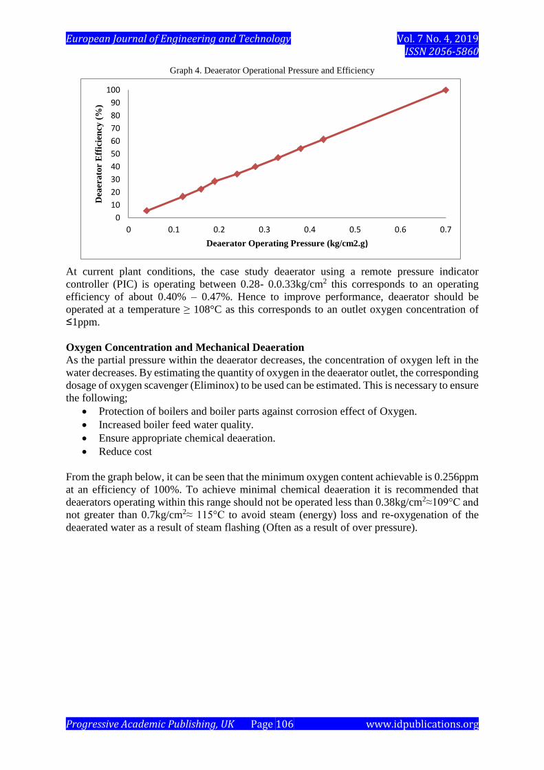
Graph 4. Deaerator Operational Pressure and Efficiency
At current plant conditions, the case study deaerator using a remote pressure indicator
controller (PIC) is operating between 0.28- 0.0.33kg/cm2 this corresponds to an operating
efficiency of about 0.40% – 0.47%. Hence to improve performance, deaerator should be
operated at a temperature ≥ 108°C as this corresponds to an outlet oxygen concentration of
≤1ppm.
Oxygen Concentration and Mechanical Deaeration
As the partial pressure within the deaerator decreases, the concentration of oxygen left in the
water decreases. By estimating the quantity of oxygen in the deaerator outlet, the corresponding
dosage of oxygen scavenger (Eliminox) to be used can be estimated. This is necessary to ensure
the following;
• Protection of boilers and boiler parts against corrosion effect of Oxygen.
• Increased boiler feed water quality.
• Ensure appropriate chemical deaeration.
• Reduce cost
From the graph below, it can be seen that the minimum oxygen content achievable is 0.256ppm
at an efficiency of 100%. To achieve minimal chemical deaeration it is recommended that
deaerators operating within this range should not be operated less than 0.38kg/cm2≈109°C and
not greater than 0.7kg/cm2≈ 115°C to avoid steam (energy) loss and re-oxygenation of the
deaerated water as a result of steam flashing (Often as a result of over pressure).

European Journal of Engineering and Technology Vol. 7 No. 4, 2019 ISSN 2056-5860
Progressive Academic Publishing, UK Page 107 www.idpublications.org
Graph 5. Oxygen Concentration in Deaerated water and Operating Temperatures
The table below outlines the results of the Oxygen continuity equation adopted to estimate the
concentration of oxygen in boiler feed water to deaerator in the absence of an online analyzer
as the case in the case study deaerator.
Table 4. Deaerator Outlet Oxygen Content at various operating conditions
Operating Pressure
(Kg/cm2)
Operating Temperature
(°C)
Solubility of oxygen in
Water (DO2)(cm2/sec)
Outlet Oxygen
concentration
(WO2(t))(ppm)
0.7 115
120 x10-6
0.256
0.43 110
110.4 x10⁻⁶
0.78
0.38 109 108.9 x10⁻⁶
0.926
0.33 108 105.7 x10⁻⁶
1.332
0.28 107
101.2 x10⁻⁶
2.22
0.24 106
99.7 x10⁻⁶
2.635
0.19963 105
97.83x10⁻⁶
3.259
0.1575561 104 96.75 x10⁻⁶
3.684
0.116684 103 94.7 x10⁻⁶
4.651
0.0384029 101
93.8 x10⁻⁶
5.15
Cost Implication of Chemical Deaeration
To achieve required chemical deaeration, a batch of Eliminox (N2H4) solution is prepared in
an injection tank using 6-Litres of Eliminox per batch, and making up tank level using
demineralised water or steam condensate. Based on the requirement to ensure that there is a
trace of Eliminox in the boiler feed water been fed to the steam drum at all times (This signifies
the complete removal of carbon dioxide and oxygen) about 18-litres of Eliminox is dosed per
day to achieve this with a constant injection pump rate of about 0.2litre/min. This volume of
Eliminox required can be reduced to about half.
0
1
2
3
4
5
6
100 102 104 106 108 110 112 114 116
Oxy
gen
co
nte
nt
in D
eaer
ato
r O
utl
et
(pp
m)
Deaerator Operating Temperature (°C)

European Journal of Engineering and Technology Vol. 7 No. 4, 2019 ISSN 2056-5860
Progressive Academic Publishing, UK Page 108 www.idpublications.org
Calculations for Chemical Deaeration Cost Implication
Theoretically, Volume of Eliminox required per 1ppm of Oxygen = 1ppm per 1ppm of Oxygen.
Injection Tank Capacity = 190 Litres
Injection rate = 0.2 litres/Min.
Eliminox Injection rate per hour = 0.2 lit
Min ×
60Min
hr= 12Litres/hr
Duration of One Batch in Injection tank 190lit
12𝑙𝑖𝑡./hr≡ 16hrs
With 6liters of Eliminox dosed per batch, =12 liters Of Eliminox is consumed per operational
day of 24hours.
Hence; Volume of Eliminox required/day =12 Litres.
Volume of Eliminox/drum = 220 Liters
Cost of 1 drum of Eliminox = #200,000
Eliminox usage per month = 12litrs
day×31days
Month= 372litres
Volume of Eliminox per month =372litres ×1drum
220litres≡ 1
1
4 drums of Eliminox
Hence,
Cost of chemical Deaeration per month ≡ #200,000.00 ×2= # 400, 000.00
Cost of chemical Deaeration per year ≡ #400,000.00 ×12= # 4,800,000.00
From oxygen concentration chart, at optimum temperature of 108°C oxygen concentration is
≈ 2.2ppm.
Hence amount of Eliminox required = 2.2 × 14 + 4 = 34.8
Amount of Eliminox required in
the solution (95% Concentration) = 34.8ppm × 100
95= 36.6ppm
Amount of Eliminox required per year 12litres
hour×8760hours
𝑦𝑒𝑎𝑟×36.6ppm of dissolved oxygen
1000ppm= 3847.392 Litres/Year
But 1-drum of Eliminox = 200Litres, hence
Eliminox Used per year =3847.392Litres
year×
1Drum
200𝐿𝑖𝑡𝑟𝑒𝑠=19.2 drums
𝑦𝑒𝑎𝑟
Annual Cost of Eliminox =19.2 drums/year × (#200,000.00)/drum
Annual Cost of Eliminox = #3,847,392/year
Cost Saving on Chemical Deaeration
Table 4 below shows the present cost of chemical deaeration, the cost of chemical deaeration
at optimum operating conditions and the cost saved on chemical deaeration if deaerator is
operated at optimum conditions.
Table 5. Shows Possible Cost Saving on Chemical Deaeration
Present Operational Cost (#) Optimum Operational Cost (#) Amount Saved (#)
# 4,8000,000.00
# 3,847,392.00
# 952,608,00
CONCLUSIONS
Corrosion poses a threat to plant operations as well as plant equipments, as a result it is
imperative to consider methods and operations which mitigate or eliminate the occurrence of
corrosion in process vessels. Hence for boiler systems in process plants, deaerators are adopted
to remove corrosion causing elements from boiler feed water to ensure boiler systems are

European Journal of Engineering and Technology Vol. 7 No. 4, 2019 ISSN 2056-5860
Progressive Academic Publishing, UK Page 109 www.idpublications.org
protected from corrosion. Furthermore, a deaerator is not only an essential auxiliary
component of plants reliable feed-water system, but the heart of a boiler mass-flow and
thermal-energy that can be used to identify energy-savings opportunities. With correct venting
rate, improved steam water contact within the deaerator, significant economic and energy
saving can be achieved with improved deaerator efficiency requiring less chemical deaeration.
This research can be adopted to simulate deaerator performance/behaviour and also predict
outlet concentration of oxygen in deaerated water.
REFERENCES
Altiar Equipment Company incorporated (2005). Water treatment technologies. Warminster,
PA 18974.
American boiler manufacturers association. (2011). Deaerator White Paper for use with
industrial, commercial and institutional boilers (pg 1-7).Vienn, Virginia.
ARI Armaturen streamline (2011). Survey No. 32/3/14, Kondhwa Budruk, Pune 411048 India.
Association of water treatment technologies Incorporated. (2001). Technical reference and
training manual; pp -3-27.
Babcock, L. & Wilcox, M. (2005). Steam its generation and use (41st ed.).
Bayvel, L., & Orzechowski, Z. (1993). Liquid Atomization (1st ed.). Washington DC: Taylor
& Francis.
Boilers and Deaeration: Available at:
https:www.lentech.com/applications/process/boiler/deaeration (2012).
Connor S, (2015). Basic Deaerator science revealed. pp. 2-50.
Deaerator and surge controls, cleaver Brooks manual, USA No. 750-183.
Deaerator principle and types: Available at: http://www.principle-types-process-control/amp
Deaerator-purpose, principle, types, process control: Available at
http://www.thermidaire.on.ca/boiler-feed.html
Deaerators and Industries: Available at:
http://www.google.com.ng/amp/chemicalengineeringsite.in/deaerators-
Gary, W. (2010). Evaluating Deaerator Operation. Jogar energy service: Available at:
http://www.chemicalengineeringsite.com/
IC Controls Limited, Boiler Dissolved Oxygen Control. (2015). (pg 4-6). Orangeville,
Ontanario.
James, M. (2004). Boilers & Deaerators. pp 142-143.
Kents Mechanical Engineers Handbook (Eleventh Edition); John Wiley & Sons (Wiley
Engineering Handbook series)
Lefebvre, A. H. (1989). Atomization and Sprays, 1st ed., Boca Raton: CRC Press.
O'Kelly, P. (2013). Computer Simulation of Thermal Plant Processes, (1st ed.). New York:
Springer.
Qingdao Chanlong Power Equipment Company Limited. (2011). Calculation sheet for
spinning-membrane deaerator.
Sharma, K. V., Suryanarayana, K. V., Sarma, P. K., Dharma, V., & Subramanyam, E. (2010).
Oxygen stripping in deaerator feed water and Condensation on spray droplets: Heat
Mass Transfer, 665-673.
Stazzone, S. (2017). Functions of boiler deaerator and how they operate.
Superior Boiler works Incorporated, Deaerator systems tray design. (2015).
US Department of Energy Efficiency & Renewable Energy. (2012). Deaerator in Industrial
steam systems. pg 1-2.

European Journal of Engineering and Technology Vol. 7 No. 4, 2019 ISSN 2056-5860
Progressive Academic Publishing, UK Page 110 www.idpublications.org
Thomas,C., Elliot, Chen, K., Swanekamp, R., (1997). Standard Handbook of power plant
engineering (2nd ed.)
Water treatment hand-book. (1991). Vol, 1-2, Degremont.