development of optimal controller for large signal and...
TRANSCRIPT

I J C T A, 9(16), 2016, pp. 8245-8255© International Science Press
Development of Optimal Controller forLarge Signal and Small Signal Model ofGas Turbine Plant using Particle SwarmOptimisationS. Selva Kumar*, Vignesh Venkiteswaran** and R. Udhayaraj**
ABSTRACT
The gap between supply and demand in electrical power system is a serious problem faced by developingnations thriving towards economic supremacy. Alternative sources other than conventional non-renewablesand distributed generation using renewable sources were looked into for overcoming energy crisis. With theadvent of heavy duty gas turbine plants using biomass fuel in the distributed generation, it is impeccable todevelop a suitable controller for the gas turbine plants operating in standalone and interconnected modes.Suitable large signal and small signal models for the gas turbine plants were considered and the secondaryproportional + Integral (PI) controllers are tuned for the models using Ziegler Nichol’s (ZN), Genetic algorithm(GA) and Particle Swarm Optimization (PSO) techniques. From transient and steady state analysis of thesystem it is found that PSO technique had provided optimal controller tuning for small and large signal modelsof gas turbine plants.
Keywords: Gas turbine model, PI controller, ZN, GA, PSO
1. INTRODUCTION
With depleting fossil fuels over the years, the need and usage of alternative using renewable sources isunder limelight. As an evolution, the power system also had moved towards distributed generation andcontrol. Heavy duty gas turbine plants fuelled by bio mass gasification units can be one of the better optionswhen it comes to distributed generation. These gas turbine plants are highly sensitive to large load changesand may go to instability if not properly controlled. The stable, economic and reliable operation of heavyduty gas turbine plant depends on the control involved.
To analyse the system under different loading conditions, suitable gas turbine model is necessary. Rowen[1] proposed a large signal model using the coefficients and constants he derived on actual experimentalresults done on the gas turbine system. He proposed speed, acceleration and temperature based control ofgas plant. Later, Balamurugan [2] had simplified that model with speed based control and with optimisedselection of rotor constants and droop settings. He also developed soft computation based secondarycontrollers for that simplified model [3, 4]. For interconnected operation of gas turbine plant with othersources like thermal and hydro and to execute load frequency control small signal model was developed forgas turbine plant [5, 6]
The speed governor is the primary controller for gas turbine plants which may be a droop or of isochronoustype. The droop governor is predominantly used type of speed governor characterised with drooping nature.
* Assistant Professor Senior Grade,
** Student Department of Electrical and Electronics Engineering Amrita School of Engineering, Coimbatore Amrita Vishwa Vidyapeetham,Amrita University, India

8246 S. Selva Kumar, Vignesh Venkiteswaran and R. Udhayaraj
Hence, the response of the system will have constant steady state error. So a suitable secondary controlleris required. The work explained in this paper aims to develop a suitable secondary controller for the largesignal and small signal models of the gas turbine plant using PSO and compare the results with the ZN andGA tuned controllers.
2. MODELLING OF GAS TURBINE PLANT
The large signal model of the gas turbine plant is developed to understand and analyse the behaviour of thesystem to change in external load. Rowen’s model is considered to be the best suited for this application asit is consistent and more adaptable to external factors. The large signal model of gas turbine plant is shownin Fig. 1 consisting of the speed governor that varies the fuel output depending on the change in loadtorque. The process variable to be controlled is the speed of the turbine.
The small signal model is used to demonstrate load frequency control and it is derived from the largesignal model. The coefficients and constants implemented in the system are as per Rowen’s model. Thesmall signal model for the gas turbine plant used in this work is shown in Fig. 2. The process variable to becontrolled in this model is change in frequency.
The system consists of the speed governor as the primary controller and a befittingly tuned secondarycontroller that control the change in frequency, �f. Fine tuning of the system so as to bring �f to zero is donewith the help of the secondary control loop using a PI controller.
3. TUNING OF SECONDARY CONTROLLER
The secondary controller used in both large signal and small signal models is a PI controller involving gainconstants K
p and K
i which is to be tuned suitably using ZN, GA and PSO techniques.
Figure 2: Small Signal Model of Gas Turbine Plant with Secondary Controller
Figure 1: Large Signal Model of Gas Turbine Plant

Development of Optimal Controller for Large Signal and Small Signal Model... 8247
3.1. Zeigler-Nichols’ method
Zeigler-Nichols’ [7, 8] method is a bench mark technique used to determine the gain constants of controllers.It involves the process of determining the ultimate gain, K
u and ultimate time period, T
u of the system by
increasing the proportional gain in the control loop till sustained oscillations with constant amplitude andfrequency is obtained for the process variable. From the values of K
u and T
u, the gain constants of PI
controller namely Kp and K
i are calculated using Equations (1) and (2).
0.45p uK K (1)
1.2 p
iu
KK
T (2)
The Ku and T
u values for large signal model were obtained as 5.575 and 1.35s respectively. Similarly for
the small signal model they are 0.7151 and 1.8s. The calculated values of PI controller gains Kp and K
i are
shown in Table 1.
Table 1ZN Tuned PI Gains for Large and Small Signal Model
Model Kp
Ki
Large Signal Model 2.508 2.322
Small Signal Model 0.3218 0.2145
3.2. Genetic Algorithm method
GA is a search algorithm that imbibes concepts of natural selection and genetic inheritance, to determinethe most optimal solution from a population of potential solutions [9, 10]. It consists of a fitness function
Figure 3: Genetic Algorithm Flow Chart
8248 S. Selva Kumar, Vignesh Venkiteswaran and R. Udhayaraj
that is to be maximised or minimised to obtain an optimal solution. For the current application, the IntegralSquare Error (ISE) is taken as the fitness function to be minimised. The various genetic operations likecross over, mutation and inversion were done over the intial population to arrive at the optimal solution asper the flow chart shown in Fig. 3.
For the systems under study, the number of variables involved is 2 in each model. The intial populationis taken as 10 with 20 bits of string length. GA is applied with cross over probability of 0.05 and mutationprobability of 0.8 for tuning the PI gain constants. The search algorithm is executed till the best value andmean value of the fitness function are equal. The GA tuned PI gain constants for large and small signalmodels were shown in Table 2.
Table 2GA Tuned PI Gains for Large Signal and Small Signal Model
Model Kp
Ki
Large Signal Model 2.0683 0.3075
Small Signal Model 0.2862 0.2232
3.3. Particle Swarm Optimization Technique
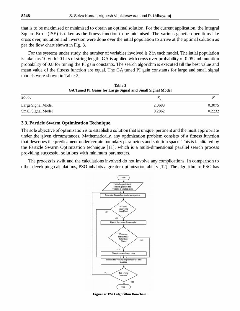
The sole objective of optimization is to establish a solution that is unique, pertinent and the most appropriateunder the given circumstances. Mathematically, any optimization problem consists of a fitness functionthat describes the predicament under certain boundary parameters and solution space. This is facilitated bythe Particle Swarm Optimization technique [11], which is a multi-dimensional parallel search processproviding successful solutions with minimum parameters.
The process is swift and the calculations involved do not involve any complications. In comparison toother developing calculations, PSO inhabits a greater optimization ability [12]. The algorithm of PSO has
Figure 4: PSO algorithm flowchart.

Development of Optimal Controller for Large Signal and Small Signal Model... 8249
been emulated from the general activities and conducts of animal civilizations that constitute the swarmsuch as bird flocking and fish schooling. Fig. 4 explains the basic flow of the processes involved.
The characteristic feature of every particle in a solution space is its velocity and position which isunique. The fitness function in this gas turbine system is the ISE which is the function to be minimised.With respect to the position of the particle for the given iteration, its personal best (pbest) position isdetermined. The best position or the most optimized solution obtained by any particle in the entire systemis called the Global best or gbest [13]. The gbest value acquired at the end of the n-iteration process is saidto be the best-suited solution. By applying the concept of PSO, the value of gain constants is obtained asshown in Table 3 for large and small signal models.
Table 3PSO tuned PI gains for Large Signal and Small Signal Model
Model Kp
Ki
Large Signal Model 1.72865 0.04925
Small Signal Model 0.2622 0.2163
4. SIMULATION RESULTS AND DISCUSSION
Both Large and Small Signal models are simulated using MATLAB-Simulink platform [14] and thecorresponding results are analysed. The large signal model is given a unit step load at time 0s. For the smallsignal model, a step load of magnitude 0.01 is given at time 0s.
4.1. Without Secondary Controller
The large and small signal models are simulated as shown in Fig. 1 and Fig 2 with the coefficients andconstants as mentioned in Appendix. The systems are loaded as specified above. Fig. 5 and Fig. 6 showsthe responses of the large signal and small signal models without secondary controller.
From the graphical response shown in Fig. 5, it is observed that the speed of the machine settles at avalue below 1 p.u. providing a constant steady state error in the process varible.
From Fig. 6, it can be noted that the system after the initial load disturbance, did not return back tonominal operating condition of zero frequency deviation and exhibiting constant steady state error. Theprimary controller in both the models was not able to bring the system back to initial operating conditionsowing to the drooping nature of the speed governor in the system and thereby insisting the importance ofthe secondary controller for fine tuning the process variable.
Figure 5: Response of Large Signal Model without Secondary controller

8250 S. Selva Kumar, Vignesh Venkiteswaran and R. Udhayaraj
4.2. With Secondary Controller
4.2.1. ZN tuned controller
The large and small signal models are enhanced with ZN tuned secondary controller with the gain constantsshown in Table 1. The systems were simulated with intial load conditions as discussed before and simulated.The time response for both models is shown in Fig. 7 and Fig. 8.
Figure 6: Response of Small Signal Model without Secondary controller
Figure 8: Response of Small Signal Model with ZN tuned PI Controller
Figure 7: Response of Large Signal Model with ZN tuned PI Controller

Development of Optimal Controller for Large Signal and Small Signal Model... 8251
The graphical responses indicate that both the systems had their process variables settled at their nominaloperating conditions with zero steady state error. But the transient response is found to have large overshootsand prolonged settling time.
4.2.2. GA tuned controller
The gain constants mentioned in Table 2, as obtained by GA tuning is used for the PI controller gains andthe system models were simulated for their responses with similar load disturbances as explained before.The responses are shown in Fig. 9 and Fig. 10.
From the responses it can be visualised that in both the models, the transient response had better featuresthan ZN tuned systems and with zero steady state error.
4.2.3. PSO tuned controller
The large and small signal models are simulated with the PI controller gains shown in Table 3 obtainedusing PSO technique. The responses were illustrated in Fig. 11 and Fig.12.
PSO tuned controllers for the two systems had provided better control on process variables in bothtransient and steady state conditions. Graphical comparison is made for both the models with all the threetuning methadologies and illustrated in Fig. 13 and Fig. 14.
Figure 10: Response of Small Signal Model with GA tuned PI Controller
Figure 9: Response of Large Signal Model with GA tuned PI Controller

8252 S. Selva Kumar, Vignesh Venkiteswaran and R. Udhayaraj
Figure 12: Response of Small Signal Model with PSO tuned PI Controller
Figure 11: Response of Large Signal Model with PSO tuned PI Controller
Figure 13: Comparison of Responses with ZN, GA and PSO tuned Controllers for Large Signal Model
Figure 14: Comparison of Responses with ZN, GA and PSO tuned Controllers for Small Signal Model

Development of Optimal Controller for Large Signal and Small Signal Model... 8253
The time domain specifications for both the models with different tuning methodologies are shown inTable 4 and Table 5.
Table 4Comparison of Time Domain Analysis of Various Controllers for Large Signal Model
Controller Tuning Peak Overshoot (p.u) Settling Time (s) Steady State Error (p.u)
ZN 2 45 0
GA 1.52 14 0
PSO 1.3864 7.88 0
Table 5Comparison of Time Domain Analysis of Various Controllers for Small Signal Model
Controller Tuning Peak overshoot (p.u) [x 10-3] Settling time (s) Steady State Error (p.u)
ZN 6.52 92 0
GA 6.46 68 0
PSO 5.92 46 0
From the comparison of time domain specifications it proves that the PSO tuned systems had bettervalues than the other two counterparts.
In addition to the time domain analysis, the performance indices [15] were calculated for the systems toprovide a quantitative analysis on the performance of the different controllers on the system. Performanceindices namely, Integral Squared Error (ISE), Integral Time Absolute Error (ITAE) and Integral Time SquaredError (ITSE) given by the Equations (3), (4) and (5) were measured from the system responses and shownin Table 6 and 7.
ISE = ��f2 dt (3)
ITAE = ��t | �f | dt (4)
ITSE = ��t (�f2) dt (5)
Table 6Comparison of Performance Indices of Various Controllers for Large Signal Model
Control Type ISE ITAE ITSE
ZN 2.209 15.81 6.74
GA 0.5762 1.856 0.3975
PSO 0.5077 1.5 0.2574
Table 7Comparison of Performance Indices of Various Controllers for Small Signal Model
Control Type ISE ITAE ITSE
ZN 7.815 0.2135 0.0016
GA 7.77 0.1825 0.001395
PSO 7.71 0.161 0.00138
*Bold indicates the least performance index
From the calculated values of the performance indices, the PSO tuned secondary controller showedleast values for both small signal and large signal models of gas turbine plant.

8254 S. Selva Kumar, Vignesh Venkiteswaran and R. Udhayaraj
6. CONCLUSION
The large signal and small signal models of heavy duty gas turbine plant were developed based on modelproposed by Rowen. The models were promptly loaded and the responses are analysed without secondarycontroller. The importance of secondary controller is realised from the responses. Secondary PI controlleris introduced in both the models with the gain constants of the controller tuned using ZN GA and PSOtechniques. From the graphical responses, time domain analysis and values of performance indices, it isobserved that the PSO tuned controller is a better controller for large signal and small signal model ofheavy duty gas turbine plant.
APPENDIX
R 2 Hz/p.u.MW; Regulation of speed governor
Kp1
100; Power system gain constant
Tp1
20 s; Power system time constant
�Pref
Change in reference power
�f Change in frequency
�PD
Change in load increment
Ku
Ultimate gain of the system
Tu
Ultimate time period of the system
Kp
Proportional gain constant
Ki
Integral gain constant
X, Y & Z X = 0; Y = 0.05; Z = 1; Speed Governor coefficients
a, b & c a = 1; b = 0.05; c = 1; Fuel system coefficients
Kf
1; Fuel System gain constant
Tf
0.4; Fuel system time constant
f1
turbine function in large signal model
Tcd
0.1; Compressor discharge volume time constant
s Laplace operator
t time in seconds
REFERENCES[1] Rowen, W.I.:Simplified Mathematical Representation of Heavy Duty Gas Turbines. ASME J. of Engi for Pow. 105
(1983) 865-869
[2] Balamurugan, S, Xavier, R. J., Jeyakumar, A.E.:Selection of governor and optimization of its droop setting and rotor timeconstant for heavy duty gas turbine plants’, Indian J. Pow. and Riv. Vall. Develop. 57(2007) 35–37
[3] Balamurugan, S, Xavier, R. J., Jeyakumar, A.E.: Fuzzy based controller for heavy duty gas turbine plant. J. of Elect.Engi., 8(2008) 61-66
[4] Balamurugan, S, Xavier, R. J., Jeyakumar, A.E.: ANN controller for heavy duty gas turbine plant,” Int. J. of Appl. Engi.Res. 3(2008)
[5] Balamurugan, S., Janarthanan, N., Vijaya Chandrakala, K.R.M.: Small and large signal modeling of heavy duty gasturbine plant for load frequency control. Elsevier – Int. J. of Elec. Pow. and Ener.Sys. 79 (2016) 84–88
Development of Optimal Controller for Large Signal and Small Signal Model... 8255
[6] Selva Kumar, S., Joseph Xavier, R., Balamurugan, S.:Small Signal Modelling of Gas Turbine Plant for Load FrequencyControl. Biennial Int. Conf. on Pow. and Ener. Sys. (2016), Bengaluru, India.
[7] Ziegler, J. G., Nichols, N. B.: Optimum setting for automatic controllers. Trans. ASME, 64(1942) 759–768
[8] Astrom, K. J., Hagglund, T. :PID Controllers, Theory, Design and Tuning. 2nd Edition, Instrument Society of America
[9] Goldberg, D.E. :Genetic Algorithms in Search, Optimization and Machine Learning. Addison Wesley Longman (1989)
[10] Balamurugan, S., Xavier, R. J., and Jeyakumar, A. E.: Application of genetic algorithm in optimal PID gain tuning forheavy duty gas turbine plant. J. of Elect. Syst., 4(2008) 33
[11] Eberhart, R, Shi, Y. : Particle swarm optimization: developments, applications and resources. Proceedings of the 2001Congress on Evolutionary Computation, 1(2001) 81 -86
[12] Gaing, Z.L:A Particle Swarm Optimization Approach For Optimum Design of PID Controller”, IEEE Trans. on Ener.Conv., 19(2004) No.2 384-391
[13] Gonçalo Pereira:Particle swarm optimization. Artificial life by example, ist.utl.pt, Oct.3, 2010. [Online]. Available http://web.ist.utl.pt/gdgp/VA/pso.pdf. [Accessed: Oct. 3, 2003]
[14] The MathWorks Inc., MATLAB User Manuals, Natick, MA: The MathWorks Inc., (2000)
[15] Gopal, M., Control Systems Principles and Design, 2nd ed., India: Tata McGraw Hill, (2002)