development of pipe-in-pipe filled with granular material ... · this failure is known as brazier...
TRANSCRIPT

Procedia Engineering 95 ( 2014 ) 232 – 240
1877-7058 © 2014 The Authors. Published by Elsevier Ltd. This is an open access article under the CC BY-NC-ND license (http://creativecommons.org/licenses/by-nc-nd/3.0/).Peer-review under responsibility of organizing committee of the 2nd International Conference on Sustainable Civil Engineering Structures and Construction Materials 2014doi: 10.1016/j.proeng.2014.12.183
ScienceDirectAvailable online at www.sciencedirect.com
2nd International Conference on Sustainable Civil Engineering Structures and Construction Materials 2014 (SCESCM 2014)
Development of pipe-in-pipe filled with granular material for flexible and ductile bending performance
Akihiro Hayashia,*, Yutaka Teradaa, Shunji Kanieb aGraduate School of Engineering, Hokkaido University, Sapporo, Japan
bFaculty of Engineering, Hokkaido University, Sapporo, Japan
Abstract
The pipe-in-pipe which the authors propose in this paper is an innovative structural material to exert a more flexible and ductile bending performance than usual steel pipes. It consists of double thin wall pipes with granular materials such as sand between the outer and inner pipes to transmit their interactive stresses within a cross section. If a single hollow pipe is subjected to bending moment, the curvature of the pipe increases with the growth in magnitude of bending moment. Upon increasing of the bending moment, the pipe finally failed by local failure, and an oval-shaped deformation of cross section was observed. This failure is known as the Brazier Effect, a kind of local buckling. However, the major parts of the pipe still keep its original strength except for the failure portion. The sand filled between the outer and inner pipes of the pipe-in-pipe prevent this local failure by transmitting the interactive stresses between the pipes. As a result, smooth and flexible bending deformation is realized even under large bending moments. The purposes of our study are to clarify the mechanism of this system and to construct the model for design of this structure. © 2014 The Authors. Published by Elsevier Ltd. Peer-review under responsibility of organizing committee of the 2nd International Conference on Sustainable Civil Engineering Structures and Construction Materials 2014.
Keywords:pipe-in-pipe, Brazier Effect, granular material, interaction, FEM fiber model
* Corresponding author. Tel.: +81-90-9435-9091.
E-mail address:[email protected]
© 2014 The Authors. Published by Elsevier Ltd. This is an open access article under the CC BY-NC-ND license (http://creativecommons.org/licenses/by-nc-nd/3.0/).Peer-review under responsibility of organizing committee of the 2nd International Conference on Sustainable Civil Engineering Structures and Construction Materials 2014

233 Akihiro Hayashi et al. / Procedia Engineering 95 ( 2014 ) 232 – 240
1. Introduction
Construction of pipeline network becomes important to securely supply oil and gas to all over the world since huge amounts of those natural resources are still reserved in undeveloped regions. For the completion of networks, pipelines may cross large faults or discontinuous permafrost regions where unexpected deformations and destructions of the pipeline may be caused by residual displacement. Applying high-strength materials to the pipeline is one of the practical solutions. Though the pipeline can resist large bending deformation with its strength, procurement of high-standard materials will increase the construction cost. On the contrary, adopting flexible and ductile pipes with common materials is an alternative and inexpensive solution. The authors have already proposed pipe-in-pipe filled with granular materials for pipelines subjected to severe bending deformation.
As Fig. 1 shows, the pipe-in-pipe consists of double thin wall pipes, and granular materials such as sand between the outer and the inner pipes to transmit interactive stress within a cross section. If a single hollow pipe is subjected to a bending moment, the curvature of the pipe increases with the growth in magnitude of bending moment (Fig. 2). By increasing the bending moment further, the pipe is finally broken by local failure with an oval-shaped deformation of the cross section as shown in Fig. 3. This failure is known as Brazier Effect, a kind of local buckling (Fig. 4). However, the major parts of the pipe still keep its initial strength, except for the failure portion. The sand filled in the core prevents this local failure by transmitting the interactive stress between the pipes. As a result, smooth and flexible bending deformation is realized even under large bending moments. The purposes of our study are to clarify the mechanism of this system, and to accomplish a simulation model for the evaluation of bending behavior.
Fig.1. Cross section of Pipe-in-pipe.
Fig.2. Deformation due to bending.
Fig.3. Brazier Effect. Fig.4. Failure of hollow single-wall pipe.
2. Bending experiments
2.1. Testing apparatus
In order to confirm the flexibility and ductility of the pipe-in-pipe, we carried out indoor experiments to observe the relationship between the bending moment and bending curvature of the pipe. The testing apparatus is illustrated in Fig. 5. The outer pipe of the specimen is supported by bending free supports (Fig. 6) at both ends, and two-point loading is applied in the mid-span. The bending moment, which is constant between two loading points, is calculated by the pushing force of actuator, the magnitude of which is measured by a load-cell. The bending deformation is monitored by three displacement gauges set between the two loading points, and the bending curvature can be obtained based on these two readings. To observe the strain of the pipe during experiments, strain gauges are equipped at the midst of pipe and the observation results are used for verification of the bending curvature.
Fig. 5. Loading apparatus. Fig. 6. Support.

234 Akihiro Hayashi et al. / Procedia Engineering 95 ( 2014 ) 232 – 240
2.2. Test specimens
First, three different types of single-wall pipes were examined. Case S1: a single-wall hollow pipe without filling; Case S2: a single-wall pipe filled with mortar; Case S3: a single-wall pipe filled with sand. In those cases, we did not apply an inner pipe, however the effect of filling material on the bending behavior can be verified. Each 1-meter length specimen is made of aluminum alloy with an outer diameter of 50 mm and thickness of 1 mm. Second, we prepared two different pipe-in-pipes filled with granular sand. The dimensions of the outer pipes are completely identical to the single wall pipes used for Case S1 to Case S3. However the diameters of the inner pipe are different; Case D30: the diameter of inner pipe is 30 mm; Case D40: the diameter of inner pipe is 40 mm. The longitudinal axe of the outer and the inner pipes should be identical and located at the center of the cross section. We provided end caps (Fig. 7) to hold the outer and the inner pipes at right position. Those end caps were equipped at the both ends of the pipe-in-pipes. When we fill the core with sand, its density should be carefully controlled. We compacted the sand by knocking the outer pipe with a soft hammer while gradually pouring sand into the core, and the sand densities were kept between 1.57g/cm3and 1.60g/cm3. The specifications of the specimens are tabulated in Table 1.
Fig.7. End cap for inner pipe.
Table 1. Specifications of specimens
Case Name Diameter of outer pipe(mm)
Diameter of inner pipe (mm)
Filling Material Number of specimen
S1 50 NA None 2 S2 50 NA Mortar 2 S3 50 NA Sand 2 D30 50 30 Sand 2 D40 50 40 Sand 2
All of the pipes are made of aluminum alloy with the length of 1 m.
2.3. Experimental results of Single-wall pipe
Fig. 8 shows the relations between the bending moment and the bending curvature for Case S1 and Case S2. The flexural rigidity of Case S2 filled with mortar was slightly improved compared to that of Case S1, but it failed at a very low curvature. On the contrary, Case S1, a hollow pipe, could bend to a much larger curvature without failure. The mechanism of this behavior can be explained as follows: (1) mortar contributes to the increase in flexural rigidity at the beginning because it resists both compressive and tensile stresses in the longitudinal direction due to bending; (2) when the tensile stress reaches to the critical strength, the flexural rigidity suddenly deteriorates locally and partially, after which (3) the bending curvature drastically accumulates at the local portion where the crack in the mortar occurred, although the rest of pipe retains its sound condition. In other words, the critical bending moment for failure is dependent on the tensile strength of the filling material when a continuous material such as mortar is used as the core material.

235 Akihiro Hayashi et al. / Procedia Engineering 95 ( 2014 ) 232 – 240
Fig. 8. Relation between bending moment and curvature for hollow and mortar filling single-wall pipe.
Interesting is the role of sand as a filling material. The effect of sand on the ductility of the pipe is surveyed by
comparing Case S1 and Case S3.Fig. 9 shows the relation between the bending moment and the bending curvature. During the elastic deformation, no difference can be seen between them. However, the critical bending curvatures of Case S3 filled with sand are much larger than those of Case S1. The sand as a filling material rarely increases the flexural rigidity because sand is not a continuous body and it has no tensile strength. The compressive stress acting in sand in the longitudinal direction is negligibly small for the flexural rigidity of the pipe. However, the author’s opinion is that the sand filled in the pipe prevents the cross section deformation (such as the Brazier Effect) of the pipe. Consequently, the pipe filled with sand, Case S3, bends smoothly without local failure, and the critical bending curvature is much larger than Case S1
Fig.9. Relation between bending moment and curvature for hollow and sand filling single-wall pipe
2.4. Experimental results of Pipe-in-pipe
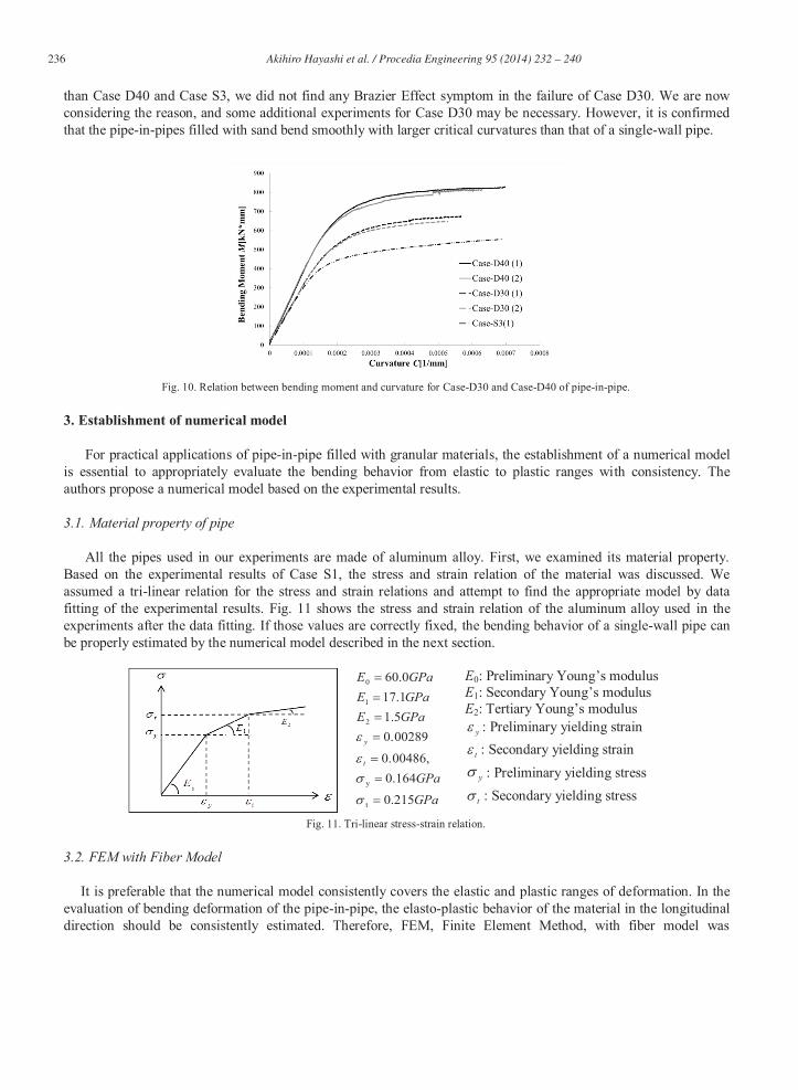
Similar to the experiments of single-wall pipes, we carried out experiments for pipe-in-pipes filled with sand. Fig. 10 illustrates the relation between the bending moment and the bending curvature compared to those of Case S3. In the cases of pipe-in-pipes, flexural rigidity is determined as a combination of the outer and the inner pipes. As shown in Fig. 10, the flexural rigidity of Case D40 is the largest in both elastic and plastic ranges. Similarly, the bearing bending moment is increased with the size in diameter of the inner pipe.
The critical bending curvature of Case D40 was 0.0007 [1/mm] and this value is almost identical with that of Case S3, a single-wall pipe filled with sand. Though the critical bending curvature of Case D30 was little smaller
236 Akihiro Hayashi et al. / Procedia Engineering 95 ( 2014 ) 232 – 240
than Case D40 and Case S3, we did not find any Brazier Effect symptom in the failure of Case D30. We are now considering the reason, and some additional experiments for Case D30 may be necessary. However, it is confirmed that the pipe-in-pipes filled with sand bend smoothly with larger critical curvatures than that of a single-wall pipe.
Fig. 10. Relation between bending moment and curvature for Case-D30 and Case-D40 of pipe-in-pipe.
3. Establishment of numerical model
For practical applications of pipe-in-pipe filled with granular materials, the establishment of a numerical model is essential to appropriately evaluate the bending behavior from elastic to plastic ranges with consistency. The authors propose a numerical model based on the experimental results.
3.1. Material property of pipe
All the pipes used in our experiments are made of aluminum alloy. First, we examined its material property. Based on the experimental results of Case S1, the stress and strain relation of the material was discussed. We assumed a tri-linear relation for the stress and strain relations and attempt to find the appropriate model by data fitting of the experimental results. Fig. 11 shows the stress and strain relation of the aluminum alloy used in the experiments after the data fitting. If those values are correctly fixed, the bending behavior of a single-wall pipe can be properly estimated by the numerical model described in the next section.
GPaGPa
GPaEGPaEGPaE
t
y
215.0
164.00.00486,
0.002895.11.170.60
t
y
2
1
0
E0: Preliminary Young’s modulus E1: Secondary Young’s modulus E2: Tertiary Young’s modulus
y : Preliminary yielding strain
t : Secondary yielding strain
y : Preliminary yielding stress
t : Secondary yielding stress
Fig. 11. Tri-linear stress-strain relation.
3.2. FEM with Fiber Model
It is preferable that the numerical model consistently covers the elastic and plastic ranges of deformation. In the evaluation of bending deformation of the pipe-in-pipe, the elasto-plastic behavior of the material in the longitudinal direction should be consistently estimated. Therefore, FEM, Finite Element Method, with fiber model was

237 Akihiro Hayashi et al. / Procedia Engineering 95 ( 2014 ) 232 – 240
introduced for the purpose. The cross section is divided into small portions and each of those is modeled as a fiber element in the longitudinal direction.
As a beam deformation theorem, Timoshenko’s beam which considers both bending and shear deformations, is adopted. First, we introduced displacements of u, v, and w as functions of the longitudinal location in x, y and z directions respectively. Similarly, x , y , z are rotation angles of displacements around the axes as indicated by their subscripts. Fig. 12 shows the coordinate system of elements. The displacements at the coordinates of x, y and z can be evaluated by Eq. (1) to (3). Here, U in Eq. (1) is the displacement in the x direction, V in Eq. (2) is the displacement in the y direction, and W in Eq. (3) is the displacement in the z direction. The variable of is a warping function. For the interpolation in the longitudinal direction, a linear shape function is adopted to prevent shear locking.
)('),()()()(),,( xzyxzxyxuzyxU xyz (1)
(2)
(3)
Fig. 12. The coordinate system of elements.
This model underlines that the evaluation of bending behaviour is consistently from the elastic to the plastic
range in material property even if the bending deformation becomes large. Finally, the element stiffness matrix [k] is described by Eq. (4). Here, [Bl] is infinitesimal displacement-strain matrix, [D] including the stress and strain relations shown in the previous section.
dxdydzBDBk l
Tl (4)
For the application of the FEM model, the cross section was divided into 24 elements in circumferential
direction and the longitudinal length is discretized into 50 elements.
3.3. Verification of Material Property and Fiber Modeling
If the material property and FEM with fiber modeling are properly assumed, the bending behavior of a single-wall pipe filled with sand, Case S3, can be numerically estimated to follow the experimental result. The comparison of the numerical estimation with the experimental results is shown in Fig. 13. Those results are almost identical to one another and it is verified that the material properties are accurately assumed and the numerical model can appropriately simulate the bending deformation.
)()(),,( xzxvzyxV x
)()(),,( xyxwzyxW x

238 Akihiro Hayashi et al. / Procedia Engineering 95 ( 2014 ) 232 – 240
Fig. 13. Relations between bending moment and curvature for experiment and numerical simulation of single-wall pipe
3.4. Applicability of superposition model for pipe-in-pipe
The sand filled in the core of pipe-in-pipe has no tensile strength. The compressive stress acting in the sand is negligibly small for the evaluation of flexural rigidity due to bending. It means that the sand as a filling material rarely contributes to the increase in the flexural rigidity of a pipe-in-pipe. Assuming that the outer and the inner pipes bend together while keeping their longitudinal axes identical, the flexural rigidity of a pipe-in-pipe can be estimated by the superposition model.
Based on this assumption, we introduced a superposition model for the pipe-in-pipe. Both outer and inner pipes are discretized into small portions with applying fiber model in their longitudinal direction. Fig. 14 demonstrates a discretization sample. It is assumed that the sand works to keep the distance between the outer and the inner pipes constant but it never contributes to the flexural rigidity. In other words, the total flexural rigidity of a pipe-in-pipe can be estimated by addition of the flexural rigidities of the two pipes.
The numerical estimation is compared with the experimental results in Fig. 15. The superposition model gives a rather accurate evaluation for the bearing capacity in bending moment within the plastic range. However, it is likely to overestimate the bending moment in the elastic range before the first yielding point. We thought that the overestimation in the elastic range is caused by the assumption that the outer and the inner pipes bend together while keeping their longitudinal axes identical. Then, we adopted a hypothesis that the curvature of inner pipe is not always same with that of outer pipe.
Fig. 14. Superposition model for numerical analysis
Fig. 15. Relation between bending moment and curvature for experiment and superposition model of pipe-in-pipe

239 Akihiro Hayashi et al. / Procedia Engineering 95 ( 2014 ) 232 – 240
3.5. Winkler spring model for granular material
Interaction due to the filling material between the outer and the inner pipes should be appropriately expressed in a numerical model to satisfy the hypothesis that the curvature of inner pipe is not always same as the outer pipe. In our experiments, the bending moment is given on the outer pipe, and the inner pipe bends as a reaction through the filling material. Accordingly, we inserted a Winkler spring between the outer and the inner pipes to represent the interaction due to the sand within the cross section. However, it never works in the longitudinal direction and never contributes to the increase in the flexural rigidity. Fig. 16 shows the Winkler spring model.
Fig. 16. Winkler spring model for numerical analysis
The most important in the numerical simulation is to decide the spring coefficient of the Winkler spring. If the
value of the spring coefficient is assumed to be zero, no interaction occurs between the pipes, and the inner pipe never bends even after the outer pipe yields. In this case, the flexural rigidity of a pipe-in-pipe is calculated identically with that of Case S3 by neglecting the existence of the inner pipe. If the value of the spring coefficient is assumed to be infinity, on the contrary, both the outer and the inner pipe bends together along same longitudinal axes, keeping their relative distance constant. The estimated result for flexural rigidity becomes identical with that by the superposition model in the previous section. We assumed various values for the spring coefficient such as k=1[kN/m], k=10[kN/m], k=100[kN/m] and k=1000[kN/m].
Fig.17 and Fig.18 show the relations between the bending moment and bending curvature for the various spring coefficients with the numerical simulation of Case S3 as compared to the experimental results. When the value of k=1[kN/m] is given to the spring coefficient, the estimated results are very close to the experimental results of Case S3. According to the increase in the spring coefficient, the flexural rigidity is improved and the simulated results for kf=1000[kN/m] becomes almost the same with the results of the superposition model.
Fig. 17. Relation between bending moment and curvature for experiments and Winkler spring model of Case D30
Fig. 18. Relation between bending moment and curvature for experiments and Winkler spring model of Case D40
From those figures, the spring coefficient of k=100[kN/m] is recommended to simulate the interactive action due
to the filling material. Since the Winker spring is a distributed and discretized spring, we calculated the reaction coefficient of foundation which is equivalent to the Winkler spring by considering its distribution density. In our simulation model, it is found that the value of k=100[kN/m] for the Winkler spring is equivalent to 10fk

240 Akihiro Hayashi et al. / Procedia Engineering 95 ( 2014 ) 232 – 240
[kgf/cm3] representing the reaction coefficient of foundation. The sand filleris in a dense condition with a density of 1.57[g/cm3] to 1.60[g/cm3]. The estimated value of the reaction coefficient of 10fk [kgf/cm3] is usually applied to sand foundation compacted to a very high density. The authors are convinced that a numerical evaluation model for a pipe-in-pipe has been successfully established to simulate the bending behavior from elastic to plastic ranges in strainconsistently.
4. Conclusion
Throughout this study, it is confirmed that the pipe-in-pipe filled with granular materials has excellent bending performance compared to usual single-wall pipes. The pipe-in-pipe bends smoothly during large bending curvatures without local failure and the experimental results show high flexibility and ductility. The numerical model we proposed in this paper simulates the bending behavior consistently from elastic to plastic ranges in strain, and interactive actions caused by the filling material can be explained by the model.
The pipe-in-pipe filled with granular materials has already been registered as a domestic patent in Japan in 2013. It can be applied as a structural material where large residual displacements often occur, e.g. regions with earthquakes by fault or regions with discontinuous permafrost. The structural dimensions of indoor experiments we carried out are relatively small when compared to real field cases for practical discussions. The size effect of the model may be considered for the evaluation of interaction due to the filling material. The authors are now planning further studies to enlarge the practical applicability with real-scale models.
References
[1]Brazier, L. G. : On the flexure of thin cylindrical shells and other “thin” sections, Proceedings of the Royal Society of London, All6, pp. 104-114, 1927
[2]Ishii, K., Makino, Y. and Kagoura, T.: Flexible Riser Technology for Deep Water Applications, OTC7726, 1996 [3]Kanie, S., Akagawa, S., Kim, K., and Mikami, T. : Estimation Method of Frost Heaving for Chilled Gas Pipeline Buried in Frost Susceptible
Soil. Current Practices in Cold Regions Engineering.ASCE Conference Proceeding Proceedings 210, 33. 2006 [4]Li, Y : The Concept of Multitube Moment Factors in a Riser system and its Applications, OTC008519, 1997 [5]Makino, Y., Ishii, K. and Fuku, T.: Development of Light-Weight Flexible Pipe, OTC7362, 1993 [6]Sato, M. and Patel, M. H. : Exact and simplified estimations for elastic buckling pressures of structural pipe-in-pipe cross-sections under
external hydrostatic pressure , Journal of Marine Science and Technology, Vol. 12(4), pp.251-262, 2007 [7]Timoshenko S. P. and Goodier J. N. : Theory of elasticity, international third edition, McGraw-Hill Inc, 1970 [8]Timoshenko S. P. and Woinowsky-Krieger, S. : Theory of plates and shells, International student edition, McGraw-Hill book company Inc,
1959 [9]William, P. J. : Pipelines and permafrost, Carlton University Press Inc., ISBN 0-88629-056-2, 1989 [10]Siegfried, M. Holzer : Computer analysis of structures, Elsevier Science Publishing Co., Inc, ISBN 0-444-00943-4, 1985