development of portable rehabilitation device using ... · pdf filedevelopment of portable...
TRANSCRIPT

Development of Portable Rehabilitation Device
Using Flexible Spherical Actuator with Built-in
Embedded Controller and Valves
Hiroaki Tamaki, Shujiro Dohta, Tetsuya Akagi, and Yasuko Matsui Department of Intelligent Mechanical Engineering, Okayama University of Science, Okayama, Japan
Email: {t12r019th, t14rm07my}@ous.jp, {dohta, akagi}@are.ous.ac.jp
Abstract—This study aims at developing a potable
rehabilitation device which can be safe to use during holding
it by both hands. In our previous study, a novel flexible
pneumatic cylinder that can be used even if it is deformed
by external force has been developed. A portable
rehabilitation device using the flexible spherical actuator
that consists of two ring-shaped flexible pneumatic cylinders
was proposed and tested. In this paper, more portable and
lower-cost rehabilitation device using the spherical actuator
that includes the built-in embedded controller and valves is
proposed and tested. The attitude control of the device using
the built-in controller is executed. As a result, the portable
rehabilitation device that it is possible to give the
rehabilitation motions to patients with sequential control
can be realized. The whole cost of the device can be reduced
by a one-third.
Index Terms—portable rehabilitation device, flexible
pneumatic cylinder, flexible spherical actuator, embedded
controller, low cost
I. INTRODUCTION
In an aging society, it is required to develop a system
to aid in nursing care [1] and to support the activities of
daily life for the elderly and the disabled [2], [3]. In
addition, the rehabilitation devices help the elderly who
was injured temporally to recover their physical ability
for keeping Quality of Life (QOL). The actuators used in
such a system need to be flexible so as not to injure the
human body [4]. The purpose of this study is to develop a
portable rehabilitation device that can be safe enough to
use it while handling it with human hands. In our
previous study, a novel flexible pneumatic cylinder that
can be used even if the cylinder is deformed by external
forces has been proposed and tested [5]. We also
developed a flexible robot arm and a spherical actuator
using the flexible pneumatic cylinders, which can be used
on a table as a rehabilitation device for human wrist and
arm [6]-[8]. A portable rehabilitation device using the
flexible spherical actuator that consists of two flexible
pneumatic cylinders was proposed and tested. The
flexible spherical actuator can create larger bending
motion along the spherical surface. However, the tested
device has many pressure supplied pipes and electric
Manuscript received May 5, 2015; revised September 1, 2015.
signal lines connected with the embedded controller and
valves. In this paper, the development of more portable
rehabilitation device will be described. In order to realize
more portable rehabilitation device, it is necessary to
unite the controller and valves into the flexible spherical
actuator. This paper also described about development of
not only portable device but also lower-cost device.
II. PREVIOUS PORTABLE REHABILITATION DEVICE
A. Flexible Pneumatic Cylinder
Fig. 1 shows the construction of a rod-less type
flexible pneumatic cylinder developed by us [5]. The
cylinder consists of a flexible tube as a cylinder and
gasket, one steel ball as a cylinder head and a slide stage
that can move along the outside of the cylinder tube. The
steel ball in the tube is pinched by two pairs of brass
rollers from both sides of the ball. The operating principle
of the cylinder is as follows. When the supply pressure is
applied to one side of the cylinder, the inner steel ball is
pushed. At the same time, the steel ball pushes the brass
rollers and then the slide stage moves toward opposite
side of the pressurized while it deforms the tube.
Figure 1. Construction of the flexible cylinder.
B. Flexible Spherical Actuator
Fig. 2 (a) shows the appearance of the previous
spherical actuator. The actuator was developed as a
rehabilitation device for shoulders and arms. It is imaged
that patients will hold both handling stages, which are top
and bottom stages in Fig. 2, by their both hands in the
rehabilitation. Two slide stages of each flexible cylinder
are not connected with one side base, that is, each slide
stage of the flexible cylinder is fixed on each handling
314
International Journal of Mechanical Engineering and Robotics Research Vol. 4, No. 4, October 2015
© 2015 Int. J. Mech. Eng. Rob. Res.doi: 10.18178/ijmerr.4.4.314-318

stage as shown in Fig. 2 (b). The size of the actuator is
260 mm in width and 270 mm in height. The total mass
of the actuator is 310 g. In addition, to measure the
attitude angle of each handling stage, two accelerometers
are used as angular sensors.
Fig. 3 shows the transient view of the movement of the
actuator. In the experiment, the sequential on/off
operation of the control valve every 0.8 seconds was done.
The supply pressure of 450 kPa is applied to the control
valve. From Fig. 3, it can be seen that the device can
create the different attitudes easily. We also observed that
the device can work smoothly while the human holds it
by both hands.
Handlingstage
Slide stage
Accelerometer
Fixed stage
Flexiblepneumaticcylinders
(a) Whole view of the actuator
(b) Detailed photo of the handling stage
Figure 2. Flexible spherical actuator.
Figure 3. Transient view of the movement of the actuator.
C. Master-Slave Attitude Control System
The angular change θ, ψ and φ defined as shown in
Fig.4 are given by the following equations, respectively
[9]. Where, Axout, Ayout and Azout are incremental A/D
values for x, y and z axes in the accelerometer.
22
1tan
zoutyout
xout
AA
A (1)
22
1tan
zoutxout
yout
AA
A (2)
zout
youtxout
A
AA22
1tan (3)
θ
ψ
φ
z
xy
Figure 4. Attitude angle (θ, ψ and φ).
Fig. 5 shows the schematic diagram of the master-slave
attitude control system of portable rehabilitation device.
The control system consists of the improved spherical
actuator with two accelerometers as a slave device, a
master device with an accelerometer, four quasi-servo
valves [10] to operate two flexible pneumatic cylinders
and a microcomputer (Renesas Co. Ltd., SH7125) as a
controller. The accelerometers were used as angular
sensors of the master and slave handling stages. The
attitude control of the device is done as follows. The
desired angles between both stages are given by the
sequential data or the master device operated by physical
therapist. For measuring the master and slave stage’s
angles, the microcomputer gets the output voltages from
each accelerometer. The angle between both handling
stages in the slave could be obtained from the calculated
angles of each stage. According to the deviation between
the master’s and the slave’s angle, the quasi-servo valves
are driven based on the control scheme, and the flexible
pneumatic cylinders are driven. The sampling period of
the control is 4 ms. The PWM period of the quasi-servo
valve is 10 ms. Both the angular measuring of the devices
and the attitude control could be realized by using an
embedded controller. Fig. 6 shows the view of the
attitude control system. The total mass of the system
315
International Journal of Mechanical Engineering and Robotics Research Vol. 4, No. 4, October 2015
© 2015 Int. J. Mech. Eng. Rob. Res.

including the controller and the valves is small, about
0.9kg.
Figure 5. Attitude control system of the device.
Figure 6. View of rehabilitation device with the attitude control system.
(a) Cross motion
(b) Circular motion
Figure 7. Transient response of stage angle using master-slave control.
D. Control Results
A master-slave control using the system was carried
out. Figs. 7 (a) and (b) show the transient responses of the
angles of the stage in the device for a cross motion and
circular motion, respectively. In both figures, broken
lines show the desired angles (θr and φr) and solid lines
show the controlled angles (θ and φ) of the slave device,
respectively. From Figs. 7 (a) and (b), it can be also
found that there is a little large error between the master
and slave angles. These errors and overshoots will be
reduced by using more robust control scheme and
adjusting the control parameters.
The estimated cost of the device is about 330US$. The
most of the whole cost is for four quasi-servo valves that
includes eight on/off valves. The cost of the quasi-servo
valves is about 270US$. It needs to decrease the whole
cost of the device so that the patients can be easily used
in their house. In addition, there are many electric signal
lines and pneumatic supply pipes in the system. These
lines prevent to give the comfortable rehabilitation for the
patient. Therefore, it is necessary to unite these
components to construct the more portable rehabilitation
device.
(a) Whole view of the actuator
(b) Detailed photo of the handling stage
Figure 8. Improved portable rehabilitation device.
III. IMPROVED PORTABLE REHABILITATION DEVICE
A. Construction
Fig. 8 (a) and (b) show the appearance of the improved
portable rehabilitation device using the spherical actuator.
In order to unite the embedded controller and valves into
the rehabilitation device, it is necessary to increase the
size of the spherical actuator to get enough space for the
316
International Journal of Mechanical Engineering and Robotics Research Vol. 4, No. 4, October 2015
© 2015 Int. J. Mech. Eng. Rob. Res.
controller. Therefore, the diameter of the ring-shaped
flexible pneumatic cylinder is changed from 260 mm to
290 mm. Two acrylic handles are installed on both
handling stages to be easy to hold. In each handling stage
has two small sized on/off valves (SMC Co. Ltd., S070C-
SDG-32) that are connected with the flexible pneumatic
cylinder. The controller that consists of three electric
boards is set on the stage. The electric circuit board has
the embedded controller (Renesas Co. Ltd., SH7125), a
serial communication board and transistors. There is
electric signal line between both handling stages to
connect from the controller to the accelerometer. A
pneumatic supply pipe is shared to four valves in the
spherical actuator. By this improvement, the device only
has a pneumatic supply pipe and two electric lines (Vcc
and GND). The size of the actuator is 290 mm in width
and 320 mm in height. The total mass of the device is
light-weight, that is 580 g, even if the device has the
whole pneumatic driving elements with controller. In
addition, by decreasing the number of valves in the
system and using the lower cost valves, the whole cost of
the device can be decreased.
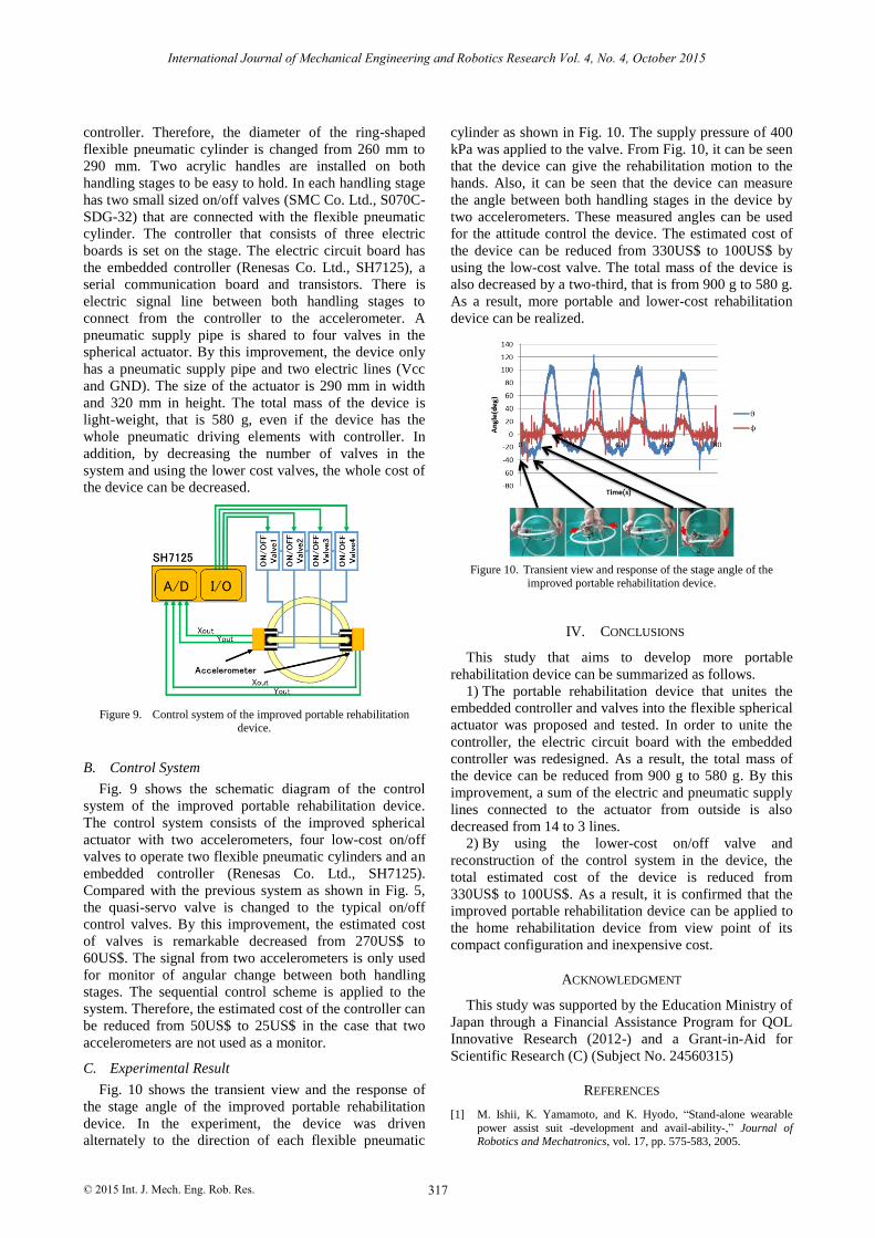
Figure 9. Control system of the improved portable rehabilitation device.
B. Control System
Fig. 9 shows the schematic diagram of the control
system of the improved portable rehabilitation device.
The control system consists of the improved spherical
actuator with two accelerometers, four low-cost on/off
valves to operate two flexible pneumatic cylinders and an
embedded controller (Renesas Co. Ltd., SH7125).
Compared with the previous system as shown in Fig. 5,
the quasi-servo valve is changed to the typical on/off
control valves. By this improvement, the estimated cost
of valves is remarkable decreased from 270US$ to
60US$. The signal from two accelerometers is only used
for monitor of angular change between both handling
stages. The sequential control scheme is applied to the
system. Therefore, the estimated cost of the controller can
be reduced from 50US$ to 25US$ in the case that two
accelerometers are not used as a monitor.
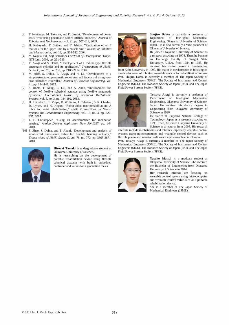
C. Experimental Result
Fig. 10 shows the transient view and the response of
the stage angle of the improved portable rehabilitation
device. In the experiment, the device was driven
alternately to the direction of each flexible pneumatic
cylinder as shown in Fig. 10. The supply pressure of 400
kPa was applied to the valve. From Fig. 10, it can be seen
that the device can give the rehabilitation motion to the
hands. Also, it can be seen that the device can measure
the angle between both handling stages in the device by
two accelerometers. These measured angles can be used
for the attitude control the device. The estimated cost of
the device can be reduced from 330US$ to 100US$ by
using the low-cost valve. The total mass of the device is
also decreased by a two-third, that is from 900 g to 580 g.
As a result, more portable and lower-cost rehabilitation
device can be realized.
Figure 10. Transient view and response of the stage angle of the improved portable rehabilitation device.
IV. CONCLUSIONS
This study that aims to develop more portable
rehabilitation device can be summarized as follows.
1) The portable rehabilitation device that unites the
embedded controller and valves into the flexible spherical
actuator was proposed and tested. In order to unite the
controller, the electric circuit board with the embedded
controller was redesigned. As a result, the total mass of
the device can be reduced from 900 g to 580 g. By this
improvement, a sum of the electric and pneumatic supply
lines connected to the actuator from outside is also
decreased from 14 to 3 lines.
2) By using the lower-cost on/off valve and
reconstruction of the control system in the device, the
total estimated cost of the device is reduced from
330US$ to 100US$. As a result, it is confirmed that the
improved portable rehabilitation device can be applied to
the home rehabilitation device from view point of its
compact configuration and inexpensive cost.
ACKNOWLEDGMENT
This study was supported by the Education Ministry of
Japan through a Financial Assistance Program for QOL
Innovative Research (2012-) and a Grant-in-Aid for
Scientific Research (C) (Subject No. 24560315)
REFERENCES
[1] M. Ishii, K. Yamamoto, and K. Hyodo, “Stand-alone wearable
power assist suit -development and avail-ability-,” Journal of Robotics and Mechatronics, vol. 17, pp. 575-583, 2005.
317
International Journal of Mechanical Engineering and Robotics Research Vol. 4, No. 4, October 2015
© 2015 Int. J. Mech. Eng. Rob. Res.
[2] T. Noritsugu, M. Takaiwa, and D. Sasaki, “Development of power assist wear using pneumatic rubber artificial muscles,” Journal of
Robotics and Mechatronics, vol. 21, pp. 607-613, 2009.
[3] H. Kobayashi, T. Shiban, and Y. Ishida, “Realization of all 7
motions for the upper limb by a muscle suit,” Journal of Robotics and Mechatronics, vol. 16, pp. 504-512, 2004.
[4] Y. Nagata, Ed., , Tokyo:
NTS Ltd., 2004, pp. 291-335. [5] T. Akagi and S. Dohta, “Development of a rodless type flexible
pneumatic cylinder and its application,” Transactions of JSME, Series C, vol. 73, no. 731, pp. 2108-2114, 2007.
[6] M. Aliff, S. Dohta, T. Akagi, and H. Li, “Development of a
simple-structured pneumatic robot arm and its control using low-cost embedded controller,” Journal of Procedia Engineering, vol.
41, pp. 134-142, 2012. [7] S. Dohta, T. Akagi, C. Liu, and A. Ando, “Development and
control of flexible spherical actuator using flexible pneumatic
cylinders,” International Journal of Advanced Mechatronic Systems, vol. 5, no. 3, pp. 184-192, 2013.
[8] H. I. Krebs, B. T. Volpe, D. Williams, J. Celestino, S. K. Charles, D. Lynch, and N. Hogan, “Robot-aided neurorehabilitation: A
robot for wrist rehabilitation,” IEEE Transactions on Neural
Systems and Rehabilitation Engineering, vol. 15, no. 3, pp. 327-335, 2007.
[9] J. F. Christopher, “Using an accelerometer for inclination sensing,” Analog Devices Application Note AN-1027, pp. 1-8,
2010.
[10] F. Zhao, S. Dohta, and T. Akagi, “Development and analysis of small-sized quasi-servo valve for flexible bending actuator,”
Transactions of JSME, Series C, vol. 76, no. 772, pp. 3665-3671, 2010.
Hiroaki Tamaki is undergraduate student at Okayama University of Science.
He is researching on the development of
portable rehabilitation device using flexible
spherical actuator with built-in embedded
controller and valves for a graduation thesis.
Shujiro Dohta is currently a professor of Department of Intelligent Mechanical
Engineering, Okayama University of Science,
Japan. He is also currently a Vice-president of Okayama University of Science.
He joined Okayama University of Science as a research associate on 1974. Then, he became
an Exchange Faculty of Wright State
University, U.S.A. from 1984 to 1985. He received his doctor degree in Engineering
from Kobe University in 1990. His major in mechatronics is focusing on the development of robotics, wearable devices for rehabilitation purpose.
Prof. Shujiro Dohta is currently a member of The Japan Society of
Mechanical Engineers (JSME), The Society of Instrument and Control Engineers (SICE), The Robotics Society of Japan (RSJ), and The Japan
Fluid Power System Society (JFPS).
Tetsuya Akagi is currently a professor of
Department of Intelligent Mechanical Engineering, Okayama University of Science,
Japan. He received his doctor degree in Engineering from Okayama University of
Science in 1998.
He started at Tsuyama National College of Technology, Japan as a research associate on
1998. Then, he joined Okayama University of Science as a lecturer from 2005. His research
interests include mechatronics and robotics; especially wearable control
systems using microcomputers and wearable control devices such as flexible pneumatic actuator, soft sensor and wearable control valve.
Prof. Tetsuya Akagi is currently a member of The Japan Society of Mechanical Engineers (JSME), The Society of Instrument and Control
Engineers (SICE), The Robotics Society of Japan (RSJ), and The Japan
Fluid Power System Society (JFPS).
Yasuko Matsui is a graduate student at Okayama University of Science. She received
the Bachelor of Engineering from Okayama
University of Science in 2014. Her research interests are focusing on
wearable control system using microcomputer and wearable control valve such as a portable
rehabilitation device.
She is a member of The Japan Society of Mechanical Engineers (JSME).
318
International Journal of Mechanical Engineering and Robotics Research Vol. 4, No. 4, October 2015
© 2015 Int. J. Mech. Eng. Rob. Res.
Soft Actuators -Forefront of Development