development ,of silane/siloxane emulsionsvuir.vu.edu.au/30253/1/thang duc nguyen.pdf · development...
TRANSCRIPT
DEVELOPMENT ,OF SILANE/SILOXANE EMULSIONS FOR APPLICATION IN BUILDING PROTECTION
A thesis submitted for the degree of Doctor of Philosophy
by
THANG DUC NGUYEN
Department of Chemistry and Biology Victoria University of Technology
January 1996
ACKNOWLEDGMENTS
I am indebted to many people for their assistance in the completion of this
research work. While it is impossible to mention all the names, I wish to thank
the following persons:
Dr. Douglas A. Kagi for his guidance, constant help and support during the
course of this research;
Mr. Gary Holliday for his support and exchange of ideas;
Dr. Maurice Porter (Maurice R. Porter & Associates, England) for his advice on
surfactants;
Dr. Andrew Smallridge for his assistance in matters relating to 29Si NMR;
Prof. John Stearne for his encouragement and support;
Associate Prof. John Casey for his constant help;
Prof. Robert Snow (RMIT), who fostered my enthusiasm m many different
ways;
The Technical Staff of the Department of Chemistry and Biology, especially Mr.
Vince Murone for technical help, Mr. Ian Sullivan and Ms. Min Nguyen for
providing useful help when desired;
Mr. Rod Flentje, Department of Civil Engineering for testing the compressive
strength of concrete;
Mr. Anthony Caselli (Tech-Dry) and all my colleagues who have contributed to
many valuable discussions.
Special thanks are due to:
My Mother for implanting in me the ambition and desire to pursue research
work;
My wife, Chau. Without her inspiration, support and encouragement this thesis
would never have been completed;

My children Joanne and Nicholas for their understanding and support during the
course of this research.
The opportunity to undertake the research work at Victoria University of
Technology under the Australian Postgraduate Research A ward (Industry)
provided by the Australian Government in conjunction with Tech-Dry Building
Protection Systems Pty. Ltd. is gratefully acknowledged.
PREFACE
This project was an industrial research project sponsored by the Australian
Government under the Australian Postgraduate Research A ward (Industry) in
conjunction with Tech-Dry Building Protection Systems Pty. Ltd as the industrial
partner.
The project was aimed at developing silane/siloxane emulsions for concrete
protection. The research area required multi-disciplinary input and the project
was oriented towards academic and commercial research with a possible market
outcome.
The academic and commercial aims of the project have been achieved. Part of
the academic results of the project have been accepted for publication as a
refereed paper:
a. "Novel Silane/Siloxane Emulsions for the Impregnation of Concrete" to be
published in Surface Coatings Australia.
The commercial basis of the results has been lodged as patent applications:
b. "Method of Producing Stable Silane/Siloxane Emulsions for Rendering
Masonry Surfaces Water Repellent", Australian Provisional Patent Application,
PM 2952, 1993.
c. "Silane/Siloxane Emulsions For Masonry Surfaces", International Patent
WO 95/16572.
ABSTRACT
Novel silane/siloxane emulsions for rendering concrete surfaces water
repellent have been developed and patented. These novel emulsions were
prepared from alkylalkoxysilanes as the base materials. One novel emulsion was
composed of an alkylalkoxysilane and a neutralised polyisobutylsiloxane latex.
The latex was prepared by the emulsion polymerisation of commercial
isobutyltrimethoxysilane. The other novel emulsion was prepared by
·emulsification of a mixture of a silicone fluid and an alkylalkoxysilane in water
with an amine soap as surfactant. A particular amine soap was chosen as a
deactivatable surfactant to deliver very little negative beading effect at the
surface of the substrate. The emulsions developed in this research contain no
solvent. Therefore they comply with various regulations regarding volatile
organic content (VOC). They are non-toxic and non-flammable, and may be
considered as environmentally friendly materials.
The novel silane/siloxane emulsions were prepared as concentrates which can
be transported and then diluted on site with water for application. They are stable
and storable as concentrates over a long period of time. The emulsions are
effectively neutral and maintain a high level of original alkylalkoxysilane on long
term storage.
)]
Experimental results indicated that the emulsions developed by the method of
this research were very effective for concrete protection due to their high
penetrating power, their stability to the alkaline environment and their ability to
protect concrete from the intrusion of water and chloride ion. Their performance
was comparable to solvent-based products in terms of stability, beading effect,
penetration depth, water repellency, alkali resistance, UV resistance and the
efflorescence resistance of the treated concrete.
The mechanism of the emulsion polymerisation process of
isobutyltrimethoxysilane, the characteristics of the polyisobutylsiloxane latex and
the properties of the novel silane/siloxane emulsions were studied in this
research.
Ill
ACKNOWLEDG:MENTS
PREFACE
TABLE OF CONTENTS
ABSTRACT 11
TABLE OF CONTENTS 1v
LIST OF TABLES x
LIST OF FIGURES XII
CHAPTER ONE. Introduction 1
CHAPTER TWO. Literature review 5
2.1. Silicone-based water repellents for the impregnation of concrete 5
2.1.1. The use of alkylalkoxysilanes for concrete protection 7
2.1.2. Aqueous silane/siloxane water repellents 10
2.1.2.1. Siliconates 11
2.1.2.2. Silanols 12
2.1.2.3. Silane and siloxane emulsions 13
2.1.2.4. Silane emulsions with silicone surfactants 18
2.1.2.5. Silicone microemulsions 18
2.1.2.6. lmpregnants for concrete 19
2.2. Emulsion stability 19
2.2.1. General considerations of emulsion stability 19
IV
2.2.2. Theories of emulsion stability
2.2.2.1. The adsorbed film theory
2.2.2.2. The electrical theory
a. The electrical double layer
b. The Derjaguin-Landau and Verwey-Overbeek (DL VO)
theory
2.3. Concrete protection through hydrophobicity
2.3 .1. Corrosion of steel in concrete
2.3.2. Factors causing reinforcing steel corrosion
2.3.3. Protective measures for reinforcing steel
2.3 .3 .1. Reinforcement protection
2.3.3.2. Hydrophobic additives
2.3 .3 .3. Protective surface coating
2.3.3.4. Protective surface impregnation
CHAPTER THREE. Materials, equipment and test procedures
3 .1. Materials
3 .1.1. Alky lalkoxysilanes
3.1.2. Surfactants
3.1.2.1. Alkylbenzenesulphonic acid
3.1.2.2. Sodium dodecylbenzenesulphonate
3.1.2.3. Amine soap
3 .1.3. Silicone fluid
v
21
21
24
24
25
32
32
34
38
39
41
41
43
44
44
44
44
44
45
45
45
3 .1.4. Octyl/methy 1 methoxysiloxane
3 .2. Equipment
3.2.1. Emulsion polymerisation reactor
3 .2.2. Sorvall RC5C centrifuge
3.2.3. IKA Ultra Turrax T25 shear mixer
3.2.4. Cambridge Du Nouy tensiometer
3.2.5. Malvern Mastersizer
3.2.6. DV-I Brookfield digital viscometer
3.2.7. Malvern Zetasizer 4
3.2.8. Headspace GC-MS chromatograph
3.2.9. Gel permeation chromatograph
3.2.10. Orion pH/ISE meter model 720-A
3 .2.11. 29Si NMR spectrometer
3 .2 .12. Q. U. V. accelerated weathering tester
3 .3. Preparation of silane/siloxane emulsions
3 .3 .1. Preparation of polyisobutylsiloxane (PIBS) latex
3.3.2. Preparation of PIBS latex/silane emulsions
3 .3 .3. Preparation of PDMS/silane emulsions
3 .4. Test procedures
3 .4.1. Freeze-thaw stability test
3.4.2. Preparation of test specimens
3.4.3. Beading effect examination
VI
45
45
46
46
46
46
47
47
48
48
49
50
51
52
52
53
55
55
56
56
56
58
3 .4.4. Measurement of penetration depth
3.4.5. Water absorption test
3 .4. 6. Alkali stability test
3.4.7. Chloride ion resistance test
3 .4. 8. Efflorescence resistance test
CHAPTER FOUR. Siloxanes for silane/siloxane emulsions and
emulsion polymerisation to prepare polyisobutylsiloxane
4.1. The use of siloxane for the preparation of novel emulsions
4.2. The mechanism of emulsion polymerisation ofIBTMS
4.2.1. The hydrolysis and condensation ofIBTMS monomer
4.2.2. The role of the surfactant in the emulsion polymerisation of
IBTMS
4.2.3. The mechanism of the emulsion polymerisation process
4.3. Characterisation of PIBS latex
4.3.1. Zeta potential of PIBS latex
4.3.2. Surface activity of PIBS latex
4.3.3. Viscosity of PIBS latex
4.3.4. Molecular weight distribution of PIBS latex
4.3.5. Particle size distribution of PIBS latex
4.4. The stability of PIBS latex
CHAPTER FIVE. Characterisation and stability of novel
silane/siloxane emulsions
VII
58
59
60
60
61
62
62
65
65
73
77
82
82
84
85
88
91
94
97
5. I. Characterisation of novel silane/siloxane emulsions 97
5. I. I. Particle size distribution of novel silane/siloxane emulsions 98
5 .1.1.1. Particle size distribution of PIBS latex/silane emulsions 98
a. Effect of solids concentration on PSD of PIBS latex/silane 100
emulsions
b. Effect of silane concentration on PSD of PIBS latex/silane 102
emulsions
c. Effect of shearing on PSD of PIBS latex/silane emulsions I 03
5. I. I .2. Particle size distribution of PDMS/silane emulsions I 06
5.1.2. Zeta potential of novel silane/siloxane emulsions 109
5 .1.3. Viscosity of novel silane/siloxane emulsions 111
5 .1.3 .1. Viscosity of PIBS latex/silane emulsions I 11
a. Effect of silane concentration on the viscosity of PIBS
latex/silane emulsions 112
b. Effect of preparation method on the viscosity of PIBS
latex/silane emulsions 117
c. Effect of solids concentration on the viscosity of PIBS
latex/silane emulsions 119
5.1.3.2. Viscosity of PDMS/silane emulsions 121
5.1.4. Preferred compositions for novel silane/siloxane emulsions 127
5 .1.5. Freeze-thaw and tropical stability of novel silane/siloxane
emulsions 127
viii
5 .1.5 .1. Freeze-thaw stability of novel silane/siloxane emulsions 127
5 .1.5 .2. Tropical stability of novel silane/siloxane emulsions 130
5 .1.6. The stability of alkylalkoxysilane in the novel silane/siloxane
emulsion
5 .2. The stability of novel silane/siloxane emulsions
5.2.1. The stability of PIBS latex/silane emulsions
5.2.2. The stability of PDMS/silane emulsions
CHAPTER SIX. The effectiveness of novel silane/siloxane emulsions
131
134
134
135
for concrete protection 13 8
6 .1. Evaluation of the performance of novel emulsions 13 8
6.2. The application mechanism of silane/siloxane emulsions 138
6.3. Factors affecting the performance of silane/siloxane emulsions 144
6.4. The beading effect and the penetration depth of the water 146
repellent
6.5. Water absorption of the treated concrete 150
6.6. Alkali stability of the impregnants in the treated concrete 154
6.7. Chloride ion resistance of the treated concrete 159
6.8. The effect of UV radiation on impregnants in the treated concrete 163
6.9. Efflorescence resistance of the treated concrete 164
CHAPTER SEVEN. Conclusions 166
REFERENCES 170
ABBREVIATIONS 182
ix
LIST OF TABLES
Page
Table 4.1. Effect of ABSA on the relative rate of hydrolysis ofIBTMS 66
Table 4.2. The effect of the leaving group on the hydrolysis rate of
isobutyltrialkoxysilanes in ABSA solution 68
Table 4.3. The effect of the alkyl group on the hydrolysis rate of
alkyltrimethoxysilanes in ABSA solution 68
Table 4.4. Assignment of 29Si NMR spectra of IBTMS and PIBS 72
Table 4.5 . Zeta potential of PIBS latex 82
Table 4.6. Surface tension of the PIBS latex at different concentrations 84
Table 4.7. Surface tension of neutralised PIBS latex 85
Table 4.8. Viscosities and yield values of polyisobutylsiloxane latex at
different concentration of solids 88
Table 4.9. Effect of surfactant concentration on the specific surface area
of the PIBS latex 94
Table 5.1. Specific surface area of the PIBS latex containing 30% solids
and PIBS latex/silane emulsions containing 18% solids 100
Table 5.2. Effect of solids concentration on the specific surface area of
the PIBS latex/IBTES emulsion 102
Table 5.3. SSA of the novel silane/siloxane emulsions 108
Table 5.4. Effect of amine soap concentration on the mean diameter of
x
the oil droplets in PDMS/IBTES emulsion
Table 5.5. Zeta potentials of the novel silane/siloxane emulsions
Table 5.6. Effect of surfactant concentration on the viscosity of
PDMS/IBTES emulsion
Table 6.1. The beading effect and penetration depth for the treated
concrete blocks
Table 6.2. The beading effect and penetration depth for the treated
mortar discs
Table 6.3. The relationship between chloride ion diffusion and the water
absorption of the treated concrete after 3 5 days test
Table 6.4. The relative reduction of chloride ion in the treated concrete
at different depths below the treated surface
Table 6.5. The beading effect of the treated concrete before and after the
UV and condensation weathering test
xi
108
110
125
148
150
161
162
163
Figure 2.1.
Figure 2.2.
Figure 2.3.
Figure 3.1.
Figure 3.2.
Figure 4.1.
Figure 4.2.
Figure 4.3.
Figure 4.4.
Figure 4.5.
Figure 4.6.
Figure 4.7.
LIST OF FIGURES
Nomenclature of the silicon compounds
Reaction of alkylalkoxysilane and concrete substrate
Schematic total energy of interaction curve for two
particles
Impregnation of the test sample
Water absorption test of treated substrate
Proposed mechanism for the hydrolysis of an alkoxy group
from IBTMS in acidic medium
29Si NMR spectra of IBTMS and PIBS
Schematic representation of stages of the emulsion
polymerisation of IBTMS
Effect of reaction time on percentage conversion of
IBTMS
Schematic representation of mixed interfacial film of
Page
7
10
31
57
59
67
71
80
81
surfactants and the OH end groups of PIBS latex particles 83
Apparent viscosity versus shear rate for PIBS latex at
different concentrations of solids 86
Flow behaviour of polyisobutylsiloxane latex at different
XII
Figure 4.8.
Figure 4.9.
concentration of solids
Molecular weight distribution of PIBS latex
Effect of reaction time on the molecular weight
distribution of PIBS latex
Figure 4.10. Effect of surfactant concentration on the molecular weight
distribution of PIBS latex
87
89
89
90
Figure 4.11. Particle size distribution of the PIBS latex 92
Figure 4.12. Effect of the concentration of surfactant on the particle
Figure 5.1.
Figure 5.2.
Figure 5.3.
Figure 5.4.
Figure 5.5.
Figure 5.6.
Figure 5.7.
size distribution of the PIBS latex
Particle size distributions of PIBS latex and PIBS
latex/silane emulsions
Effect of solids concentration on the PSD of the PIBS
latex/IBTES emulsion
Relationship between SSA and silane concentration
Effect of shearing time on the SSA of the PIBS
latex/IBTES emulsion
Effect of shearing speed on the SSA of the PIBS
latex/IBTES emulsion
Particle size distribution of the PIBS latex/silane emulsions
and PDMS/silane emulsions
Apparent viscosity versus shear rate for PIBS latex/IBTES
emulsions at different concentrations of silane
Xlll
93
99
101
103
105
106
107
113
Figure 5.8.
Figure 5.9.
Flow behaviour of PIBS latex/IBTES emulsions at
different concentrations of silane
Apparent viscosity versus shear rate for PIBS latex/OTES
emulsions at different concentrations of silane
Figure 5 .10. Flow behaviour of PIBS latex/OTES emulsions at different
concentrations of silane
Figure 5 .11 . Apparent viscosity versus shear rate for PIBS latex/silane
emulsion
Figure 5 .12. Effect of shearing time on the viscosity of PIBS
114
115
116
117
latex/IBTES emulsion 118
Figure 5.13. Effect of adding method on the viscosity of PIBS
latex/IBTES emulsion
Figure 5.14. Flow behaviour of PIBS latex/IBTES emulsions at
different concentrations of solids
Figure 5 .15. Apparent viscosity versus shear rate for PDMS/IBTES
emulsions at different concentrations of silane
Figure 5.16. Apparent viscosity versus shear rate for PDMS/OTES
emulsions at different concentrations of silane
120
120
122
123
Figure 5.17. Apparent viscosity versus shear rate for novel emulsions 124
Figure 5.18. Effect of PDMS concentration on the viscosity of
PDMS/IBTES emulsion 124
Figure 5.19. Effect of the speed of the shear mixer on the viscosity of
xiv
PDMS/IBTES emulsion
Figure 5.20. Effect of shearing time on the viscosity of the
PDMS/IBTES emulsion
Figure 5.21. Headspace GC-MS chromatogram of IBTES, OTES and
PIBS latex/IBTES emulsion which was stored at room
temperature for 11 months
Figure 5.22. Schematic representation of the steric stabilisation of an oil
droplet by PDMS
Figure 6.1.
Figure 6.2.
Coalescence of spherical particles by viscous flow caused
by surface tension forces
Coalescence of spherical particles caused by capillary
forces
126
126
133
136
141
141
Figure 6.3. Schematic representation of the capillary force 143
Figure 6.4. Water absorption of treated and untreated concrete 151
Figure 6.5. Water absorption of concrete treated with IBTES
Figure 6.6.
Figure 6.7.
Figure 6.8.
impregnants
Water absorption of concrete treated with PIBS
latex/silane emulsions
Water absorption of concrete treated with diluted
emulsions
Reduction of water absorption of the treated concrete after
one day test
xv
152
152
153
154

Figure 6.9. Alkali resistance of impregnated concrete 155
Figure 6.10. Alkali resistance of substrates treated with IBTES
impregnants 156
Figure 6.11. Alkali resistance of substrates treated with OTES
impregnants 157
Figure 6.12. Alkali resistance of substrates treated with OTES
impregnants 158
Figure 6.13. Reduction of water absorption of the treated concrete after
one day sponge test in 1 Oo/o KOH solution 158
Figure 6.14. Chloride ion diffusion through concrete substrates treated
with diluted IBTES impregnants containing 20% silane
after 3 5 days test 160
Figure 6 .15. Chloride ion diffusion through concrete substrates treated
with diluted OTES impregnants containing 20% after 3 5 162
days test
Figure 6.16. Reduction of water absorption of the treated concrete
before and after 1500 hours UV and condensation
weathering test 164
xvi
CHAPTER ONE
Introduction
Concrete is one of the most versatile and durable construction materials. The
high degree of durability of concrete under normal conditions of exposure has
been shown by the vast number of structures in which concrete has been used
successfully over the past 100 years or so. However, concrete is not immune to
the action of many chemical substances entering from the surrounding
environment. It has become evident that concrete, especially reinforced concrete
is the subject to a number of mechanisms of deterioration. The corrosion of steel
in concrete has received increasing attention in recent years because of its
widespread occurrence in certain types of structures and the high cost of repairs.
Corrosion of reinforced steel in concrete is a complex process and the
deterioration of steel-reinforced concrete is affected by various factors. The main
factors responsible for the corrosion of steel reinforcement in concrete are
chloride ion, and carbonation of the concrete due to carbon dioxide. These
factors and the presence of moisture and oxygen, interrupt the passivating film
due to alkalis on the embedded steel and this leads to corrosion.
The corrosion of reinforcing steel in concrete, either due to the ingress of
chloride ions or the carbonation of the concrete is now widely known and both
these mechanisms of deterioration involve moisture as a main factor. Water
carries harmful substances into concrete. The presence of water in the concrete
also lowers the electrical resistivity of the concrete which leads to corrosion of
the reinforcing steel.1.2'3'4 Water creates the electrolyte portion of the corrosion
cell inside the concrete and supports electrochemical corrosion of the steel. It has
been reported that the corrosion rate of embedded steel in concrete structures
would be reduced if the moisture content in concrete is minimised, even when
concrete is carbonated or contaminated with chloride ions. 5•6
•7 Therefore, making
the concrete water repellent is a practical way to protect the steel from corrosion
because water is an essential element of deterioration and by excluding external
water, the rate of the corrosion process may be greatly reduced.
Alkylalkoxysilanes have been shown to be very effective in the protection of
structural concrete against corrosion of embedded steel,8•9
•10 and have been used
for making masonry and other substrates water repellent for many years. Silanes
were first proposed as impregnants for concrete in 1969 by Dynamit Nobel AG in
West Germany. Since then, a large number of chemical companies in the world
have attempted to develop their own materials for concrete protection, and silanes
in various organic solvents such as alcohols, or hydrocarbons, have been in the
market for many years. However, the solvents used to carry the active material to
2
the concrete substrate are generally flammable and have become increasingly
expensive. In addition, the odour, the environmental effects and the physiological
effects of organic solvents are important factors against the use of organic
solvents. With the advent of volatile organic compound (VOC) emission
regulations, the use of organic solvents in silane and siloxane formulations must
be limited or eliminated.
Water-based materials in the form of the alkali metal organosiliconates have
been used for many years. These solutions are highly alkaline and are therefore
difficult to handle and are corrosive. In addition, the alkali metal
methylsiliconates are not suitable for the treatment of alkaline substrates
containing free lime and having a pH of 8 or more. 11
In recent years, vanous aqueous emulsion-type silicone compositions have
been developed in Germany, the United States and Japan in an attempt to
overcome the problems of solvent-based products and the alkalinity of
organosiliconates. However, the performance of the commercially available
emulsions and compositions is not comparable to organic solvent-based silane
products in terms of stability, penetration depth, and the beading effect of the
treated substrate. Therefore, it is continually desirable to provide alternative
aqueous water repellent silane emulsions which are stable, capable of effectively
impregnating alkaline substrates and achieving a desirable water repellent effect.
3
The object of this research project was to develop stable silane/siloxane
emulsions for concrete protection which may be delivered to the substrate in
water and where the penetration into the substrate is similar to that achieved with
organic solvent-based materials. It was aimed at solving complex problems
relating to the preparation, stability and the performance qualities of
silane/siloxane emulsions.
The essential requirements for the development of silane/siloxane emulsions in
this research were:
a) the selection of raw materials was limited to commercially available
materials;
b) the technology would be industrially applicable;
c) the emulsions would have a long shelf life and the active alkylalkoxysilanes
would not be hydrolysed in the emulsions during storage;
d) the emulsions could be prepared as concentrates which may be diluted with
water to achieve a stable emulsion for low concentration application;
e) the performance of the novel emulsions in terms of beading effect,
penetration depth, alkali stability, water absorption, chloride ion resistance and
UV resistance of the treated substrates, would be comparable to organic solvent
based products containing the same concentration of alkylalkoxysilane.
4
CHAPTER TWO
Literature review
2.1. Silicon-based water repellents for the impregnation of concrete
Organo-silicone compounds such as siliconates, silanes, siloxanes and
polysiloxanes have been used for the impregnation of mineral building materials
for many years. Water repellent treatment of concrete with organo-silicone
compounds has many advantages. Organo-silicone compounds are hydrophobic
materials or materials which become hydrophobic on application to building
substrates. They have the ability to impart concrete surfaces with water repellent
properties and therefore prevent harmful salts dissolved in water entering the
concrete structure. As the silicone treatment merely coats the walls of the
capillaries and pores and does not seal the openings of the capillaries, there is no
obstruction to the passage of water vapour. In general the impregnation causes
no effect on appearance, therefore, it is practically impossible to distinguish a
treated concrete surface from an untreated surface. Untreated surfaces darken on
wetting with water which does not occur with water repellent surfaces.
According to Wittmann, 12 the speed of calcification, particularly m fresh
concrete, will be slightly increased by the use of water repellents. The
impregnated concrete surfaces have less tendency to become dirty. This is due to
the inactivation of capillary absorptivity and the dirt deposited on the treated
surface is not washed into the capillary system of the concrete when it rains, but
5
stays on the surface and is washed away. A further advantage of impregnated,
prefabricated concrete components is evident if the concrete tends to form a
network of hairline cracks. There is reduced absorbency in the region of the
cracks as the dirt cannot accumulate there, thus preventing the area from
becoming unsightly, even after a period of several years. Lime erosion on
prefabricated concrete parts can be prevented by carrying out in-plant
impregnation in good time. The impregnants may be re-applied after some years
in certain circumstances and some form good primers for other types of coating.
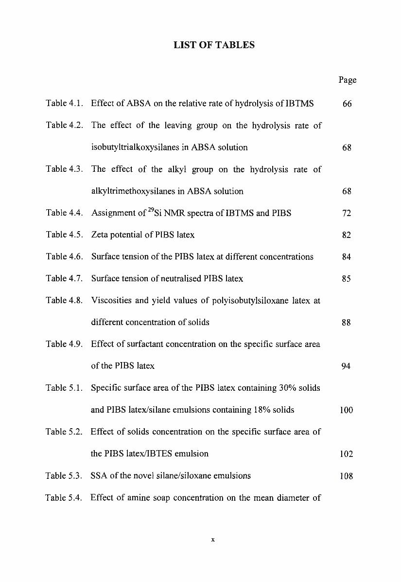
Silicon compounds can be divided into three broad classes - monomers,
oligomers and polymers - and they can be further classified according to the
nature of the functional groups attached to the silicon atom. The hydrocarbon
groups in silicon compounds are referred to as "organofunctional groups" while
the hydrolysable groups such as chloro or alkoxy attached to the silicon atom are
referred to as "silicon functional groups". The chloro or alkoxy functional groups
provide a position on silicon to react with siliceous and similar substrates, while
organofunctional groups provide hydrophobicity to the film lining the capillaries
of the substrates.
The types of silicon materials currently available in the market can be
classified into three categories. These are Q-structure materials (silicates)
containing four silicon functional groups and no organofunctional groups, T-
6
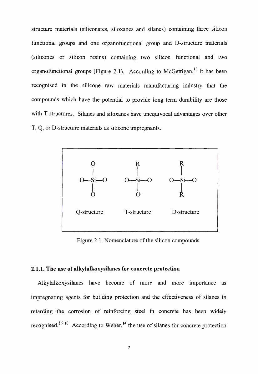
structure materials (siliconates, siloxanes and silanes) containing three silicon
functional groups and one organofunctional group and D-structure materials
(silicones or silicon resins) containing two silicon functional and two
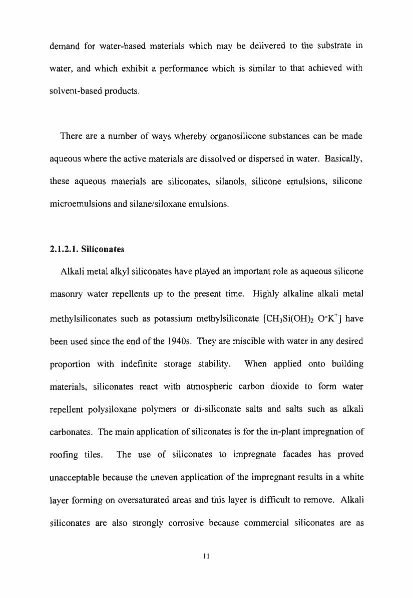
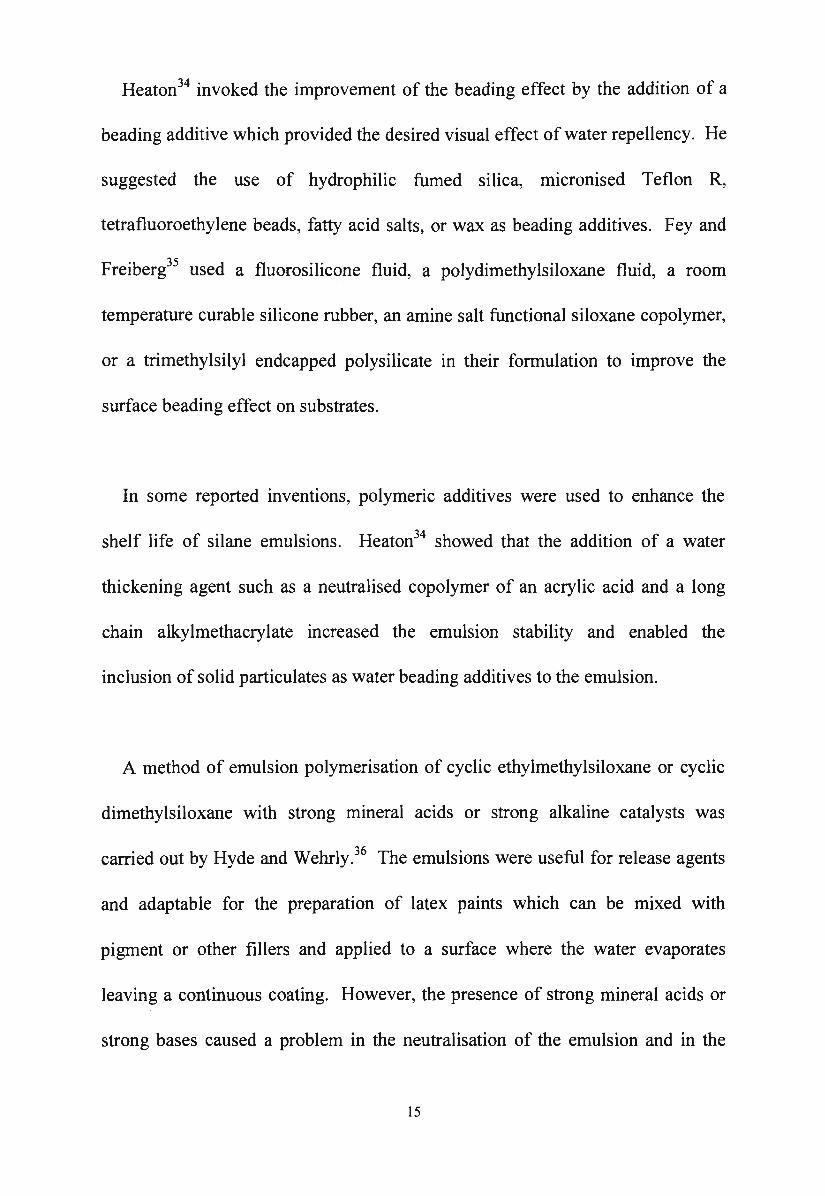
organofunctional groups (Figure 2.1 ). According to McGettigan, 13 it has been
recognised in the silicone raw materials manufacturing industry that the
compounds which have the potential to provide long term durability are those
with T structures. Silanes and siloxanes have unequivocal advantages over other
T, Q, or D-structure materials as silicone impregnants.
0
I R
I i 0-Si-O 0-Si-O 0-Si-O
I I I 0 0 R
Q-structure T -structure D-structure
Figure 2.1 . Nomenclature of the silicon compounds
2.1.1. The use of alkylalkoxysilanes for concrete protection
Alkylalkoxysilanes have become of more and more importance as
impregnating agents for building protection and the effectiveness of silanes in
retarding the corrosion of reinforcing steel in concrete has been widely
. d 8 9 10 A d" W b 14 h f ·1 ~ . recognise . ' ' ccor mg to e er, t e use o s1 anes ior concrete protection
7
has many advantages. Silanes have great penetrating power into substrates due to
their small molecular size, and therefore they can provide long-term protection to
reinforced concrete. The substrates to be treated with silanes do not need to be
air dry and silanes improve the frost resistance and the freeze-thaw durability of
the treated concrete in field exposure. 12,15
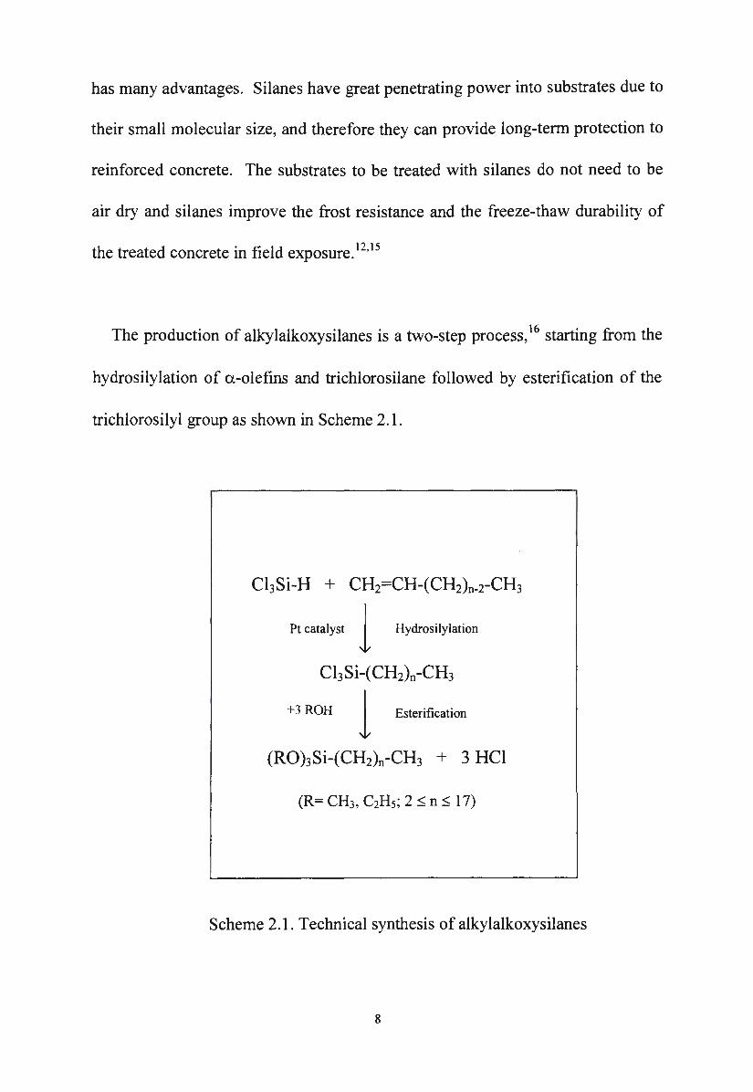
The production of alkylalkoxysilanes is a two-step process, 16 starting from the
hydrosilylation of a-olefins and trichlorosilane followed by esterification of the
trichlorosilyl group as shown in Scheme 2.1.
ChSi-H + CH2=CH-(CH2)n-i-CH3
Pt catalyst 1 Hydrosilylation
ChSi-(CH2)n-CH3
+3 ROH 1 Esterification
Scheme 2.1. Technical synthesis of alkylalkoxysilanes
8
Alternative synthetic methods of producing alkylalkoxysilanes have been
reported. They include the hydrosilylation of a-olefins with trialkoxysilanes, 17'18
the reaction of tetraalkoxysilanes with alkyl-Grignard compounds19•20 or the so
called direct synthesis from the silicon element and alkyl chlorides21 with
subsequent esterification of the trichlorosilyl group.
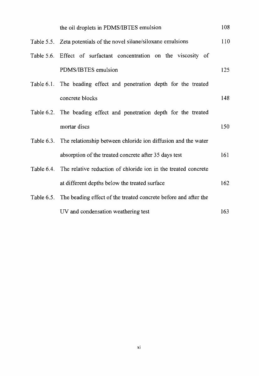
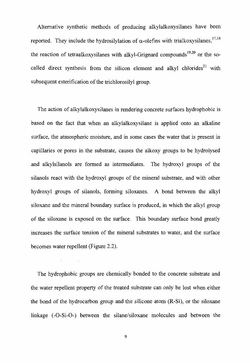
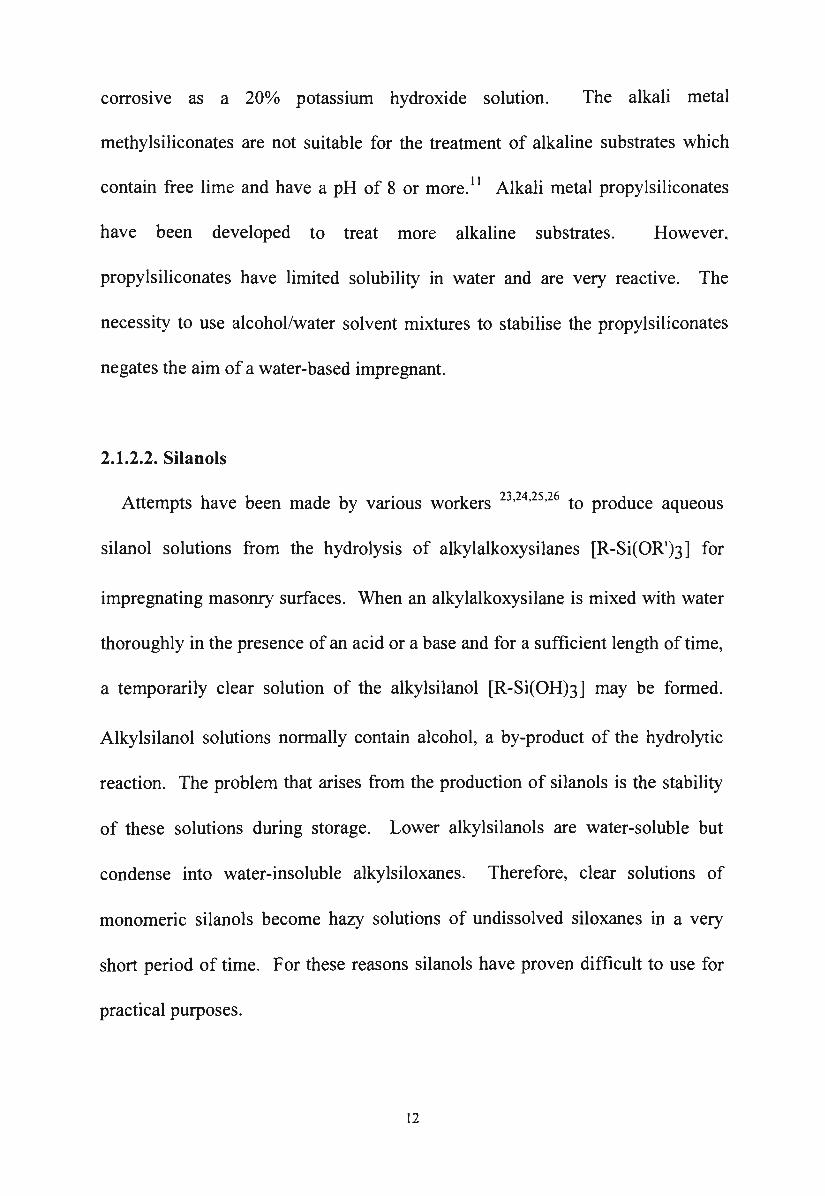
The action of alkylalkoxysilanes in rendering concrete surfaces hydrophobic is
based on the fact that when an alkylalkoxysilane is applied onto an alkaline
surface, the atmospheric moisture, and in some cases the water that is present in
capillaries or pores in the substrate, causes the alkoxy groups to be hydrolysed
and alkylsilanols are formed as intermediates. The hydroxyl groups of the
silanols react with the hydroxyl groups of the mineral substrate, and with other
hydroxyl groups of silanols, forming siloxanes. A bond between the alkyl
siloxane and the mineral boundary surface is produced, in which the alkyl group
of the siloxane is exposed on the surface. This boundary surface bond greatly
increases the surface tension of the mineral substrates to water, and the surface
becomes water repellent (Figure 2.2).
The hydrophobic groups are chemically bonded to the concrete substrate and
the water repellent property of the treated substrate can only be lost when either
the bond of the hydrocarbon group and the silicone atom (R-Si), or the siloxane
linkage (-0-Si-O-) between the silane/siloxane molecules and between the
9
silicone and the substrate is destroyed. In the first case, a Si-C bond is extremely
strong and in the second case, the only reagents which will break the Si-0 bond
belong to the same group of materials required to destroy the -Si-O-Si-0- bonds
of the concrete itself. 22
R R R R I I I I
-Si-O-Si--O-Si---0-Si-
I I I I 0 0 0 0
I I I I -Si--O-Si---0-Si--O-Si-
I I I I
}-+ Hydrophobic layer
___. Permanent bonding
}-+ Building material surface
Figure 2.2. Reaction of alkylalkoxysilane and concrete substrate
2.1.2. Aqueous silane/siloxane water repellents
Solutions of silanes/siloxanes in various solvents such as alcohols, or
hydrocarbons, have been used for treating masonry surfaces for many years. In
general, with the correct choice of active material, these products have been
technically successful in terms of good penetration depths, low water absorption
of the treated substrate and alkali stability of the final polymer. However, the
limitations of the organic solvent-based solutions are the toxicity and
flammability of the solvent employed. Moreover, the expense and difficulty of
the safe storage and transport of flammable and toxic solvents is also a factor
against the use of solvent-based products. Therefore, there is now an increasing
10
demand for water-based materials which may be delivered to the substrate in
water, and which exhibit a performance which is similar to that achieved with
solvent-based products.
There are a number of ways whereby organosilicone substances can be made
aqueous where the active materials are dissolved or dispersed in water. Basically,
these aqueous materials are siliconates, silanols, silicone emulsions, silicone
microemulsions and silane/siloxane emulsions.
2.1.2.1. Siliconates
Alkali metal alkyl siliconates have played an important role as aqueous silicone
masonry water repellents up to the present time. Highly alkaline alkali metal
methylsiliconates such as potassium methylsiliconate [CH3Si(OH)2 o-K+] have
been used since the end of the 1940s. They are miscible with water in any desired
proportion with indefinite storage stability. When applied onto building
materials, siliconates react with atmospheric carbon dioxide to form water
repellent polysiloxane polymers or di-siliconate salts and salts such as alkali
carbonates. The main application of siliconates is for the in-plant impregnation of
roofing tiles. The use of siliconates to impregnate facades has proved
unacceptable because the uneven application of the impregnant results in a white
layer forming on oversaturated areas and this layer is difficult to remove. Alkali
siliconates are also strongly corrosive because commercial siliconates are as
I I
corrosive as a 20% potassium hydroxide solution. The alkali metal
methylsiliconates are not suitable for the treatment of alkaline substrates which
contain free lime and have a pH of 8 or more. 11 Alkali metal propylsiliconates
have been developed to treat more alkaline substrates. However,
propylsiliconates have limited solubility in water and are very reactive. The
necessity to use alcohol/water solvent mixtures to stabilise the propylsiliconates
negates the aim of a water-based impregnant.
2.1.2.2. Silanols
Attempts have been made by various workers 23•24
•25
·26 to produce aqueous
silanol solutions from the hydrolysis of alkylalkoxysilanes [R-Si(OR1)3] for
impregnating masonry surfaces. When an alkylalkoxysilane is mixed with water
thoroughly in the presence of an acid or a base and for a sufficient length of time,
a temporarily clear solution of the alkylsilanol [R-Si(OH)3] may be formed.
Alkylsilanol solutions normally contain alcohol, a by-product of the hydrolytic
reaction. The problem that arises from the production of silanols is the stability
of these solutions during storage. Lower alkylsilanols are water-soluble but
condense into water-insoluble alkylsiloxanes. Therefore, clear solutions of
monomeric silanols become hazy solutions of undissolved siloxanes in a very
short period of time. For these reasons silanols have proven difficult to use for
practical purposes.
12
2.1.2.3. Silane and siloxane emulsions
Aqueous emulsions of organopolysiloxane oils have been developed by
Koerner et al. 27 and water-based silicone resin dispersions28 have also been
reported. These emulsions are unsuitable for impregnation of concrete because of
the relatively large size of the polysiloxane and the large particle size of the
emulsion. They are normally used as hydrophobic additives in plaster, aerated
concrete and paints, or as binders in silicone emulsion paints.
De Pasquale and Wilson29 prepared an aqueous silane emulsion as a masonry
water repellent which comprised an alkylalkoxysilane, an emulsifier and water.
The emulsifier was the sorbitan of a fatty acid ester having a
hydrophilic/lipophilic balance (HLB) value in the range from 4.3 to 11.4. The
emulsions prepared in this manner showed acceptable penetration depths and
acceptable water absorption values. However, surfaces treated with this emulsion
do not exhibit a good beading effect, possibly due to the adsorbed non-ionic
surfactant at the surface undergoing rewetting on exposure to water. This effect
causes a wetting of the very surface of the substrate and therefore would not be
acceptable in freezing climatic conditions. In addition pollutive substances could
be carried into the substrate in this wetted layer.
Alkylalkoxysilanes are liable to undergo hydrolysis and a subsequent
condensation reaction when incorporated in an emulsion. In order to overcome
13
this problem, Wilson30 used a buffering agent such as sodium bicarbonate
(NaHC03). The buffering agent enabled the addition of a biocide to the emulsion
without a change in the pH of the emulsion.
Deactivatable surfactants are defined as those which decompose and lose their
surface active characteristics as a result of an inherent characteristic of the
surfactant. This characteristic may be due to a reaction with other materials
which are present in a mineral substrate or by a reaction which can be initiated
after the impregnation of the mineral substrate. Fatty acid esters, silica esters31 or
esters and alcohol-alkylene adducts32 have been discussed as deactivatable
surfactants by Plihringer. However, the practicability of these ideas was not
delineated. The use of an amine soap as a deactivatable surfactant has been used
in an industrial process for the treatment of particulates by Raleigh.33 Silicate
particulate matter such as perlite and vermiculite was treated with an emulsion of
a polysiloxane with the emulsifier as the ammonium salt of a long chain aliphatic
carboxylic acid. The beading effect was activated by heating. Following
treatment of the silicate particulate matter, the particles were heated and the
silicone fluid formed a coating on the silicate surface and the ammonia
evaporated to leave the oily aliphatic carboxylic acid on the surface. This
concept had not been adapted to impregnants for masonry.
14
Heaton34 invoked the improvement of the beading effect by the addition of a
beading additive which provided the desired visual effect of water repellency. He
suggested the use of hydrophilic fumed silica, micronised Teflon R,
tetrafluoroethylene beads, fatty acid salts, or wax as beading additives. Fey and
Freiherg35 used a fluorosilicone fluid, a polydimethylsiloxane fluid, a room
temperature curable silicone rubber, an amine salt functional siloxane copolymer,
or a trimethylsilyl endcapped polysilicate in their formulation to improve the
surface beading effect on substrates.
In some reported inventions, polymeric additives were used to enhance the
shelf life of silane emulsions. Heaton34 showed that the addition of a water
thickening agent such as a neutralised copolymer of an acrylic acid and a long
chain alkylmethacrylate increased the emulsion stability and enabled the
inclusion of solid particulates as water beading additives to the emulsion.
A method of emulsion polymerisation of cyclic ethylmethylsiloxane or cyclic
dimethylsiloxane with strong mineral acids or strong alkaline catalysts was
carried out by Hyde and Wehrly.36 The emulsions were useful for release agents
and adaptable for the preparation of latex paints which can be mixed with
pigment or other fillers and applied to a surface where the water evaporates
leaving a continuous coating. However, the presence of strong mineral acids or
strong bases caused a problem in the neutralisation of the emulsion and in the
15
removal of the catalysts. Furthermore, for the best result a separate emulsifying
agent needed to be employed in this method and the stability of the emulsions
may change when additional materials such as pigments are added. The
polymerisation and copolymerisation of silcarbanes were carried out by Findlay
and Weyenberg37 in an aqueous medium where the silcarbanes were in a
dispersed state with the presence of a surface active sulphonic acid catalyst. The
polymerisation process proceeded at the desired temperature until the desired
increase in molecular aggregation was obtained. The organopolysiloxane latex
emulsions prepared in this manner were suitable for release coatings. However,
they apparently were not stable on storage and could not form a tough elastomer
for coating applications. According to Gee, 38 a typical problem encountered with
emulsion polymerisation of cyclic polysiloxanes was the presence of an
unemulsified silicone oil layer or very large silicone oil droplets in the final
product of the process. Complete elimination of the silicone oil layer could not
be achieved unless the cyclic siloxane was pre-emulsified using mechanical
means prior to polymerisation The author then developed a method of producing
a stable and oil-free emulsion which did not contain any unemulsified silicone
material and did not produce unemulsified silicone oil or polymers upon ageing.
The polymerisation process involved the opening of cyclic siloxane rings using
an acid or base catalyst in the presence of water. The products of the opening of
the cyclic rings were polysiloxane oligomers with terminal hydroxyl groups.
These oligomers then reacted with each other or with other siloxane reactants
16
through a condensation process to form polysiloxane polymers or copolymers.
The polysiloxane polymers then precipitated and aggregated to form particles
which were stabilised at a specific particle size in water by the ionic and non
ionic surfactants. Polysiloxane latex emulsions are stable and have very fine
particle sizes. They are not suitable for the impregnation of concrete. They are
added to aqueous paints to make them water repellent and to prolong shelf life.
They are also used as binders for silicone paints or added to dry mixes of building
materials, e.g. for making high grade, water repellent mortar.
Silane/siloxane emulsions have been developed recently by Scharnberg et al. 39
These inventors revealed that the emulsion of a mixture of octyltriethoxysilane
and a methylethoxypolysiloxane imparts a better water repellent effect than the
effect from emulsions made with either a silane or a siloxane alone. The
penetration depth of these emulsions was not significant on concrete substrates.
In addition, on neutral substrates the development of water repellent effect was
very slow or problematical.
Other research groups have committed significant resources to the research and
development of deep penetrating silane emulsions with good surface beading
effect with no success.40'41 This may be attributed to the polar/non-polar nature
of silane molecules and the degree of difficulty of obtaining a stable emulsion
system with such molecules. Furthermore, the added parameters of achieving
17
limited surface wetting effect from the surfactant together with deep penetration
of the active materials present significant obstacles to the researcher.
2.1.2.4. Silane emulsions with silicone surfactants
The difficulty encountered in the art of developing emulsions of polar silane
raw materials with limited surfactant wetting effect has encouraged other
developments. Goebel et al. 42 have developed new surfactants which are reactive
silicone surfactants. These surfactants have been used to develop novel silane
emulsions where the surfactant may co-polymerise with the silane base material.
2.1.2.5. Silicone microemulsions
Mayer et al. 43 have developed silicone microemulsions as aqueous masonry
water repellents. Silicone microemulsions have the advantage of being solvent
free, stable in concentrate form, easy to use, and have extremely fine-particle
size. However, the application in concrete protection has not been widely
accepted due to problems of cost (silicone microemulsion reqmres a large
quantity of amino-functional silicone), very short lifetime of the diluted
microemulsion and the products do not penetrate very well into concrete
substrates.
18
2.1.2.6. Impregnants for concrete
The present solutions of siliconates or silanols and the present emulsions of
siloxanes and silanes do not offer satisfactory water-based impregnants for
concrete. Microemulsions have been presented as a valid alternative but the cost,
lifetime and performance leave something to be desired. An innovative emulsion
has been offered by Goebel et al.42 but a new class of surfactants had to be
synthesised and this presents an obstacle to commercialisation. The
silane/siloxane emulsions developed by Scharnberg et al. 39 suffer from poor
penetration ability and difficulty of development of water repellent effect on
neutral substrates.
2.2. Emulsion stability
2.2.1. General considerations of emulsion stability
An emulsion is an heterogeneous system consisting of at least one immiscible
liquid dispersed in another in the form of droplets, which are usually within the
size range of 0.1 to I 00 µm in diameter. Emulsions are inherently unstable
systems and the risk of deterioration is higher than with other non-emulsified
products and thus stability is considered as the most important physical property
of the emulsion in industrial application. There is the added dimension with
hydrolysable moieties of chemical stability.
19
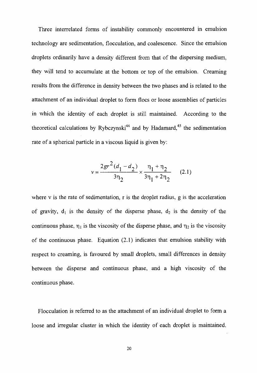
Three interrelated forms of instability commonly encountered in emulsion
technology are sedimentation, flocculation, and coalescence. Since the emulsion
droplets ordinarily have a density different from that of the dispersing medium,
they will tend to accumulate at the bottom or top of the emulsion. Creaming
results from the difference in density between the two phases and is related to the
attachment of an individual droplet to form floes or loose assemblies of particles
in which the identity of each droplet is still maintained. According to the
theoretical calculations by Rybczynski44 and by Hadamard,45 the sedimentation
rate of a spherical particle in a viscous liquid is given by:
where v is the rate of sedimentation, r is the droplet radius, g is the acceleration
of gravity, d1 is the density of the disperse phase, d2 is the density of the
continuous phase, ri 1 is the viscosity of the disperse phase, and ri 2 is the viscosity
of the continuous phase. Equation (2.1) indicates that emulsion stability with
respect to creaming, is favoured by small droplets, small differences in density
between the disperse and continuous phase, and a high viscosity of the
continuous phase.
Flocculation is referred to as the attachment of an individual droplet to form a
loose and irregular cluster in which the identity of each droplet is maintained.
20
Flocculation as well as coalescence increases the effective particle size and thus
leads to an increased rate of sedimentation. Forces responsible for flocculation
are London-van der Waals attraction forces which are frequently counteracted by
electrical repulsion. Flocculation may also be due to the interaction of the
flocculating agent with the emulsifier.
Coalescence is a phenomenon in which two or more droplets are joined
together to form a larger droplet which has a greater volume, but has a smaller
interfacial area. Coalescence cannot take place until two or more droplets are in
contact. Therefore, coalescence must be preceded by flocculation. The
coalescence rate most likely depends on the film-film surface chemical repulsion
and on the degree of irreversibility of film desorption.
2.2.2. Theories of emulsion stability
2.2.2.1. The adsorbed film theory
The effect of the emulsifier on the interfacial tension of the emulsion system
has long been recognised. Since emulsions present a large interface area, any
reduction in interfacial tension must reduce the driving force towards coalescence
and should promote stability. The lowering of the interfacial tension, while
important, cannot totally represent the effect of the emulsifying agents. The
lowering of interfacial tension by the emulsifying agent facilitates the formation
of droplets but does not necessarily increase the stability of the emulsion. In
21
addition, this also does not explain the effectiveness of non-surface active
materials, e.g. gums, finely-divided solids and other additives m stabilising
emulsions.
The role of the emulsifier in stable emulsions has been studied by
Bancroft,46'47 Harkins,48 Schulman and Riley49 and Becher.50 They indicated that
the emulsifying agent is concentrated at the interface and forms an interfacial
film which exerts a stabilising influence. The interfacial film is an oriented
monomolecular one, with the polar groups oriented towards the water phase and
the non-polar hydrocarbon chains oriented towards the oil. Consequently, the
droplet will be covered by a more or less dense protecting layer which will hinder
the coalescence of the droplets. According to King,51 the interfacial tension plays
a doubtful role in the stability of emulsions, but the interfacial adsorption of the
emulsifying agent is vital. King considered that the strength and the compactness
of the interfacial film are the most important factors favouring emulsion stability.
Stable emulsions can be prepared by using a combination of two or more
emulsifying agents. This phenomenon was studied by Schulman and Cockbain. 52
They showed that mixed emulsifying agents often lead to more stable emulsions
due to the formation of a complex film at the water-oil interface. The resulting
interfacial film is a closed-packed monolayer which possesses greater strength
and resistance to rupture, hence the emulsion droplets would be less liable to
22
coalescence and the emulsion becomes more stable. In contradiction to the
observations of Schulman and Cockbain, 52 Kremnev53 showed that the
thixotropic behaviour of mixed emulsifiers plays an important role in the
stabilisation of concentrated emulsions. According to Kremnev, highly stable
concentrated emulsions of benzene in water could be achieved by the use of
thixotropic mixtures of aliphatic alcohols and sodium oleate, owing to their
capacity of rapid restoration of the thixotropic structures which were perturbed in
the emulsifying process.
Emulsions with greater stability can also be obtained by the use of certain
macromolecular emulsifying agents such as proteins, gums, starches and certain
synthetic polymers (e.g., polyvinyl alcohol). It has been known that these
compounds adsorb at the oil-water interface and because of their multiplicity of
hydrophilic and hydrophobic groups, each molecule is attached at many points
and therefore are strongly held at the interface. The formation of tough skins
between oil and aqueous solutions of macromolecular substances such as gums
and proteins have been reported by Serralach and Jones.54'55 The work of Biswas
and Haydon56•57
•58
•59 showed that there is a direct correlation between emulsion
stability and the visco-elastic parameters of films of emulsifiers formed at the oil
water interface. Nielsen et al.60 correlated mechanical properties of various
macromolecular stabilised interfaces with droplet stability. They chose the
"surface rigidity" as the parameter to be studied rather than the elastic modulus.
23
However, Lawrence61 has questioned the choice of rigidity as a stabilising factor
due to the fact that a rigid film may not be able to "heal" a small disturbance in
the interfacial region. It seems probable that an effective macromolecular
emulsifier must form an elastic gel, swollen by the continuous phase, and any
attempt to thin this gel is opposed by very large osmotic forces. 62
2.2.2.2. The electrical theory
a. The electrical double layer
Practically, all the particles in aqueous suspensions carry a charge resulting
from dissociation of surface groups, adsorption of ions, isomorphic substitution
of ions, accumulation (or depletion) of electrons at the surface, and adsorption of
polyelectrolytes or charged macromolecular species. The . distribution of ions
around a charged particle is determined by electrical interaction with the surface
and the mixing tendency of thermal motion. Ions with opposite charges
( counterions) will be attracted to the surface and can be either closely associated
with the surface or distributed in some way into the solution. This leads to the
formation of an electrical double layer.
The structure of the electrical double layer is generally regarded as consisting
of two regions: an inner, compact layer known as the Stem layer that includes
ions bound relatively strongly to the surface by adsorption, and an outer, diffuse
layer known as the Gouy (or Gouy-Chapman) layer in which ion distribution is
24
determined by a balance of electrostatic forces and random thermal motion. As
particles approach each other, they begin to influence each other as soon as the
double layer overlaps. The repulsive electrostatic forces arise from interactions
of the surface charges of the particles and the diffuse portions of the electrical
double layer as charged particles move closely together . The inner, or Stern
layer does not have a direct role in the interactions between surfaces since it has
only several molecules of thickness. However, it has a significant indirect role in
these interactions in determining the value of the potential of the diffuse portion
of the double layer.63
Within a low ionic strength solution, the diffuse layer of counterions around
the particles extends to a considerable distance and particles begin to repel each
other when their diffuse layer overlaps. The repulsion can occur at quite large
separations. Within a higher ionic strength solution, the diffuse layer is less
extensive and the particles need to approach each other quite closely before
repulsion occurs. Interparticle repulsion is an important stabilising mechanism in
an oil/water emulsion. This prevents the close approach of the particles or
droplets and prevents coalescence.
b. The Derjaguin-Landau and Verwey-Overbeek (DLVO) theory
Colloidal particles present in a dispersion medium are always subject to
Brownian motion, and the resultant collisions between particles are frequent. The
25
stability of the system is thus determined by the interaction between the particles
during such a collision. Two basic interactions are discernible. One is the
electrostatic repulsion and the other is the London-van der Waals attraction
between the particles. A colloidal dispersion is only stable when the repulsive
force is sufficiently strong to counteract the van der Waals forces.
The repulsion between particles arises from two different sources, one is from
the overlap of electrical double layers on the particles, and the other from the
interaction between adsorbed layers of non-ionic materials, including adsorbed
molecules of the dispersion medium.
A theory relating surface charge to the stability of a colloidal system was
developed independently by Derjaguin and Landau64 and Verwey and Overbeek65
(the DL VO theory). According to the DL VO theory, the stability of a colloidal
system is determined by a balance of the van der Waals attractive energy and the
electrical repulsive energy. The total potential energy VT between the two
particles is given by:
(2.2)
where VA is the van der Waals attractive potential energy and V R is the repulsive
potential energy.
26
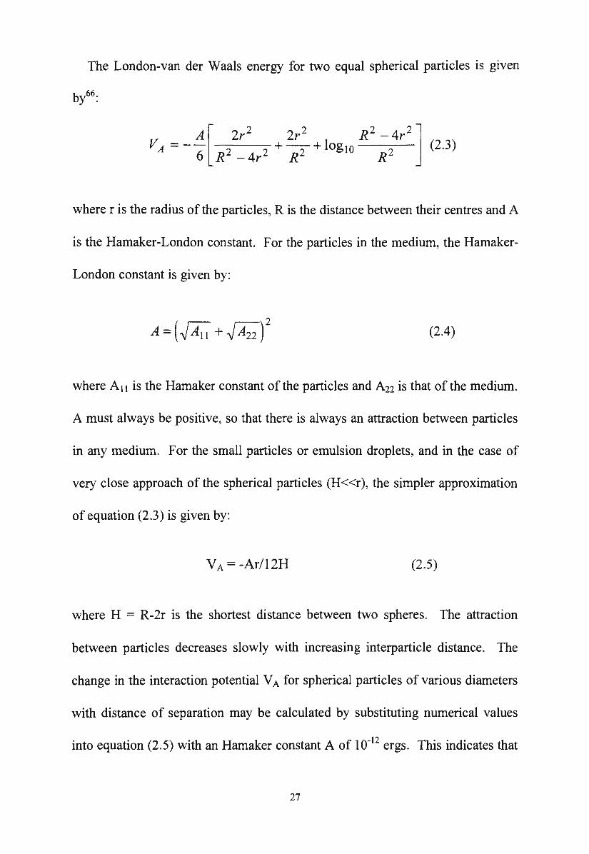
The London-van der Waals energy for two equal spherical particles is given
A[ 2r2
2r2
R2
- 4r2
] VA=-- 2 2 +-2 +log10 2 (2.3)
6 R -4r R R
where r is the radius of the particles, R is the distance between their centres and A
is the Hamaker-London constant. For the particles in the medium, the Hamaker-
London constant is given by:
(2.4)
where A 11 is the Hamaker constant of the particles and A22 is that of the medium.
A must always be positive, so that there is always an attraction between particles
in any medium. For the small particles or emulsion droplets, and in the case of
very close approach of the spherical particles (H<<r), the simpler approximation
of equation (2.3) is given by:
VA= -Ar/12H (2.5)
where H = R-2r is the shortest distance between two spheres. The attraction
between particles decreases slowly with increasing interparticle distance. The
change in the interaction potential VA for spherical particles of various diameters
with distance of separation may be calculated by substituting numerical values
into equation (2.5) with an Hamaker constant A of 10-12 ergs. This indicates that
27
the attraction between larger particles is greater than the attraction between the
smaller particles.67
The interaction between two charged particles was first formulated correctly
by Derjaguin and Landau64 and Verwey and Overbeek.65 However, the exact
equations for the interaction of spherical particles are complex. In the presence
of symmetrical electrolytes, the potential energy of repulsion is found to depend
on three dimensionless groups:
v R = f ( KH, Kr' Ze\jf olkT) (2.6)
where r is the radius of the particle, H = R-2r is the shortest distance between two
spheres, Z is the valency of the symmetrical electrolyte, e is the fundamental unit
of electric charge, \jJ0 is the surface potential and K is the Debye-Hi.ickel screening
parameter which is proportional to the square root of the ionic strength.
As the interaction of two particles is considered to occur via overlap of the
diffuse layer, the strength of the interaction may be determined by the potential at
the compact layer and diffuse layer boundary (\J18) and not by the intrinsic surface
potential \J1o· The compact-layer/diffuse layer boundary potential \jJi; is not
directly measurable and electrokinetic, or zeta potential data obtained from
microelectrophoresis measurements are normally used as the best approximation
28
available for \Jlo The zeta potential (s) is the potential at the surface of shear
between a particle and its diffuse layer which is created as the particle migrates in
an applied electric field. It is assumed that the surface shear lies close to the
compact layer/diffuse layer boundary and thus s and 'Vo should be very similar.
Although the validity of this assumption may be questionable, the advantage of
this assumption, however, is thats is readily determined experimentally, whereas
\Jlo is not. It is usually held that the zeta potential is a better guide to latex
stability than is 'Vo as calculated from the notional surface charge density.68
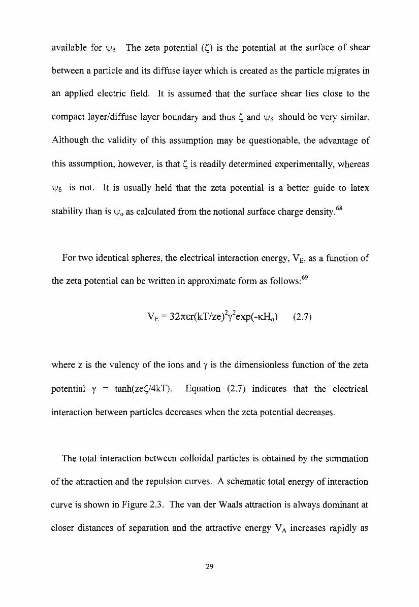
For two identical spheres, the electrical interaction energy, VE, as a function of
the zeta potential can be written in approximate form as follows: 69
VE= 32m~;r(kT/ze)2y2exp(-tll0) (2.7)
where z is the valency of the ions and y is the dimensionless function of the zeta
potential y = tanh(zes/4kT). Equation (2.7) indicates that the electrical
interaction between particles decreases when the zeta potential decreases.
The total interaction between colloidal particles is obtained by the summation
of the attraction and the repulsion curves. A schematic total energy of interaction
curve is shown in Figure 2.3. The van der Waals attraction is always dominant at
closer distances of separation and the attractive energy VA increases rapidly as
29
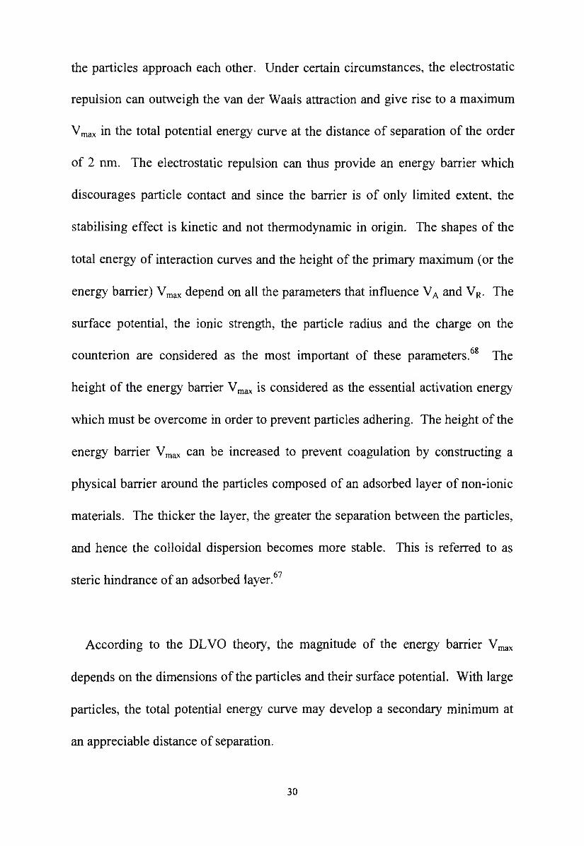
the particles approach each other. Under certain circumstances, the electrostatic
repulsion can outweigh the van der Waals attraction and give rise to a maximum
V max in the total potential energy curve at the distance of separation of the order
of 2 nm. The electrostatic repulsion can thus provide an energy barrier which
discourages particle contact and since the barrier is of only limited extent, the
stabilising effect is kinetic and not thermodynamic in origin. The shapes of the
total energy of interaction curves and the height of the primary maximum (or the
energy barrier) Vmax depend on all the parameters that influence VA and VR. The
surface potential, the ionic strength, the particle radius and the charge on the
counterion are considered as the most important of these parameters. 68 The
height of the energy barrier V max is considered as the essential activation energy
which must be overcome in order to prevent particles adhering. The height of the
energy barrier V max can be increased to prevent coagulation by constructing a
physical barrier around the particles composed of an adsorbed layer of non-ionic
materials. The thicker the layer, the greater the separation between the particles,
and hence the colloidal dispersion becomes more stable. This is referred to as
steric hindrance of an adsorbed layer. 67
According to the DL VO theory, the magnitude of the energy barrier V max
depends on the dimensions of the particles and their surface potential. With large
particles, the total potential energy curve may develop a secondary minimum at
an appreciable distance of separation.
30
ro ~
c Q) ~
0 0...
a:: >
<(
>
' ' ' ' ' ' '
/
\,/ Repulsion VR
/ /
/
', Total potential energy VT '
..... /
' '
-_...
' '............ Separation - ----Secondary minimum
/~A . . V 1 ttract1on A
Primary minimum
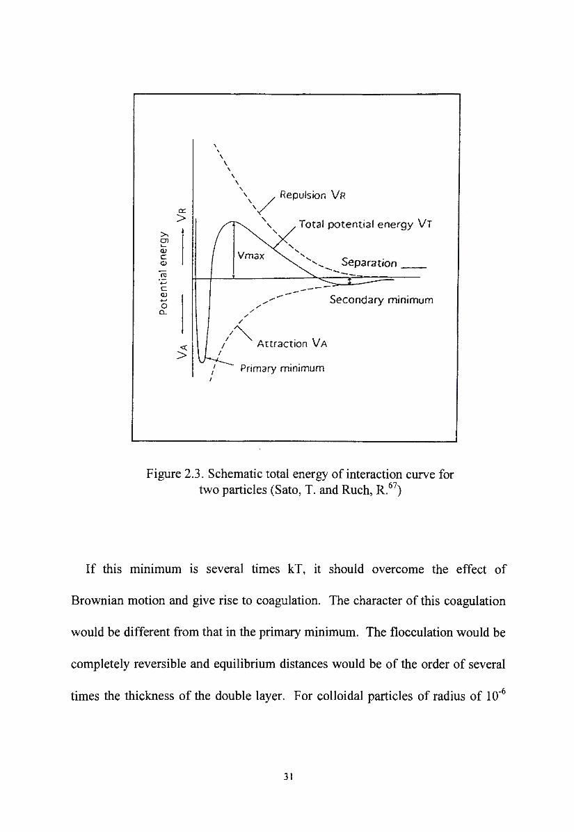
Figure 2.3. Schematic total energy of interaction curve for two particles (Sato, T. and Ruch, R.67
)
If this mm1mum is several times kT, it should overcome the effect of
Brownian motion and give rise to coagulation. The character of this coagulation
would be different from that in the primary minimum. The flocculation would be
completely reversible and equilibrium distances would be of the order of several
times the thickness of the double layer. For colloidal particles of radius of 10-6
31
cm or smaller, no secondary minimum appears in the total energy of interaction
curve and therefore flocculation is not observed.
2.3. Concrete protection through hydrophobicity
2.3.1. Corrosion of steel in concrete
When the reinforcing steel corrodes, the concrete deteriorates. Deterioration
of concrete due to corrosion results because the products of the corrosion process
build up and occupy a greater volume than the embedded steel, and therefore
exert substantial stress on the surrounding concrete. As a consequence, corrosion
causes staining, cracking and spalling of the concrete.
The corrosion of steel in concrete is a result of an electrochemical process
involving one or more chemical processes and a flow of electricity. The flow of
electricity in the electrochemical process is entirely an internally generated one
and does not involve any external source of electricity. In electrochemical
corrosion in concrete, the galvanic cell is formed in various ways and requires the
presence of an electrolyte, that is, water containing dissolved substances whose
ions can conduct electricity. Therefore, permanently dry concrete will not
support electrochemical corrosion of the embedded steel. Another fundamental
requirement for the formation of a galvanic cell is that there must be present two
dissimilar metals coupled in the same electrolyte or two similar metals
metallically coupled in a different electrolyte. In the latter case, which is of
32
prime importance to the corrosion of steel in concrete, the different electrolyte
results from the different concentrations of moisture, oxygen that comes from the
air, or dissolved substances existing from place to place in the same concrete
structure. The formation of different electrolytes at the anode and cathode is due
to the differences in permeability of the concrete in anodic and cathodic regions.
Even in concrete which is of uniform permeability, the difference in salt
concentration in anodic and cathodic regions still exists due to differences in the
environments to which various parts of the concrete members are exposed. The
two metallic surfaces in different electrolytes act as cell electrodes in the concrete
structure. The metallic surface where the protective film in concrete is poor will
act as an anode while the metallic surface where there is a good protective film
will act as a cathode. Electron current will flow from the anode to the cathode
through the embedded steel then through the electrolyte back to the anode to
complete the electrical circuit. The principal chemical reaction at the anode is as
shown in equation (2.8)
2+ Fe ~ Fe + 2e- (2.8)
The iron ions react further with water and oxygen that are present in the
concrete to from rust. The chemical reactions at the cathode may vary depending
on circumstances, but the principal one related to the corrosion of steel in
concrete is as shown in equation (2.9)
33
~o + H20 + 2e· 2 2 20H- (2.9)
The rate of this reaction is affected by different factors such as the relative size
of the electrodes, the concentration of oxygen, the temperature, and the electrical
resistivity of the electrolyte. The corrosion of reinforcing steel in concrete will
not take place if for any reason, the chemical reactions at the electrodes do not
occur and the galvanic cell does not operate.
2.3.2. Factors causing reinforcing steel corrosion
Corrosion in reinforced steel in concrete is affected by various factors such as
chloride ion, carbon dioxide, oxygen and water.7
Chloride ion is the most prevalent and damaging cause of corrosion of
reinforcing steel in concrete. Chloride ions are introduced into concrete in a
variety of ways. They are intentionally added as an accelerating admixture (such
as CaC12) , accidentally included as contaminants in aggregates or penetrate the
concrete from de-icing salts, marine environment, fog or mist. Concrete
normally provides a high degree of protection against corrosion to embedded
steel due to the formation of a thin protective film of gamma iron oxide on the
steel surface. However, this passivating film is destroyed when sufficient salt
(chloride ion) penetrates to the steel surface. It is well known that even very
small concentrations of chloride ions can break the passivating film. Chlorides
may be present in concrete in a number of states. However, it is believed that
34
only the free chloride ions influence the degradation of reinforced concrete by
causing corrosion of embedded steel. 70
Carbon dioxide (C02) plays a dominant part in damaging reinforced concrete.
It is present at a high concentration in the atmosphere. When concrete contacts
carbon dioxide from the air or carbon dioxide dissolved in water, carbonation
occurs. Carbonation is the effect of carbon dioxide in the air on Portland cement
products, mainly calcium hydroxide [Ca(OH)i] in the presence of moisture. The
Ca(OH)2 is converted to calcium carbonate [CaC03] by absorption of C02.
(2.10)
Carbonation reduces the pH value of the concrete from around 12 to 9 and
below. If the carbonation zone reaches the steel at this low pH, the passivity of
the steel surface in the concrete is destroyed and corrosion of steel is likely to
start. Carbonation proceeds from the surface of the concrete inwards and the rate
of the carbonation process is extremely slow. It has been shown by Tutti71 and
Lawrence 72 that carbonation takes place on the exposed surface and gradually
moves into the concrete. The rate of progress of the carbonation front is
proportional to the square root of time ( Jt ).
Carbonation of concrete exposed to the atmosphere is inevitable, but its
significance to the durability of reinforced concrete is only important under
35
certain conditions. If the cover zone of the embedded steel is permeable and the
cover depth is low, then the carbonation front can reach the reinforcement in a
relatively short period of time . The presence of chlorides, even in an alkaline
environment will exacerbate the corrosion process. The actual rate of
carbonation depends on the permeability of the concrete, its moisture content, the
concentration of carbon dioxide in the surrounding environment and the relative
humidity of the ambient medium. The moisture content is considered to be a
very important factor which causes the corrosion of the reinforcing steel in
carbonated concrete. It has been shown by the work of Volkwein and
Springenschmid6 in Germany that even if the concrete was carbonated, in dry
concrete, corrosion was not exhibited. This was confirmed by ACI Committee
222 Report, 7 which indicated that in the interior of building_s, carbonation of the
concrete past the embedded steel can occur with no resultant corrosion due to the
dry state of concrete.
Corrosion of steel in concrete is an electrochemical process and the availability
of oxygen at the cathode is one of the main factors for the chemical reaction. In a
cathodic reaction, the oxygen has to be in a dissolved state. According to
Gonzalez et al., 73 oxygen diffusion alone will not accelerate the corrosion rate
and the corrosion mechanism in some cases does not require oxygen diffusion.
Concrete absorbs water through its capillaries and pores. Water absorption
increases the moisture content in concrete. Through the capillary system, water
36
conveys harmful substances such as salts into concrete, which can cause severe
damage to the embedded steel. It has been reported that the majority of damage
to concrete bridges is caused by the penetration of contaminated water through
the cover to the embedded steel. 74
The electrical resistivity of the concrete depends on the moisture content of the
concrete. Dry concrete has been found to have a higher resistivity than water
saturated concrete. Gj0rv et al. 1 indicated that progressive drying of initially
water-saturated concrete results in electrical resistivity increasing from about
7xl03 ohm.cm to about 600xl03 ohm.cm. Field observations by Tremper et al.2
indicated that when the resistivity exceeds a level of 50 to 70x 103 ohm.cm, steel
corrosion would be negligible. Browne3 quoted values of resistivity of I Ox I 03
ohm.cm whilst Cavalier and Vassie4 quoted the value of 12xl03 ohm.cm above
which corrosion induced damage is unlikely even in the presence of chloride
ions, oxygen, and moisture. The work of Browne, 3 Cavalier and Vassie, 4 and
Wiss, Janney, Elstner Associates5 showed that when the concrete is kept dry,
corrosion of the embedded steel is very slow or insignificant, even in the
presence of significant chloride ion concentrations. This insignificant corrosion
rate in dry concrete is due to the corrosion reaction not having the electrolyte
portion available to support the ionic conduction of current in the corrosion cell.
Diagnostic studies on concrete in the field by Volkwein and Springenschmid6
also showed that even if the concrete was carbonated, corrosion of the embedded
37
steel was not apparent if the concrete was dry. Therefore, the "keeping dry"
effect has been shown to significantly reduce corrosion when the concrete is
contaminated with chloride ions or when the concrete is carbonated.
2.3.3. Protective measures for reinforcing steel
Several strategies have been developed to inhibit corrosion of reinforcing steel.
These strategies are based largely on work that has been done in recent years on
bridge-deck problems. The possible strategies include protective coatings on the
embedded steel, suppression of the electrochemical process (cathodic protection),
protective surface coating of the concrete surface and protective impregnation of
the concrete surface.
2.3.3.1. Reinforcement protection
Many substances are used as additives to concrete to inhibit corrosion of the
reinforcing steel. Such chemicals may act either to suppress the anodic reaction
by stabilising the passive oxide film or by forming a new insoluble coating
( chromates, phosphates), or to suppress the cathodic reaction by scavenging
oxygen (nitrites, benzoates, stannous and ferrous salts).75 However, when used in
quantities sufficient to be effective in inhibiting corrosion, some of these
substances may seriously reduce the concrete strength. In addition, when used in
sufficient concentration to deliver an effect the cost may be significant as they are
added to the bulk concrete.
38
Protective coatings of reinforcing steel in concrete structures has been
recommended to protect reinforcing steel from corrosion. Metal coatings, such
as zinc galvanising, are often used to protect steel from corrosion and galvanised
reinforcing bars have been used successfully in concrete. Other metals, such as
cadmium, nickel, and copper have also been tested. Zinc and cadmium provide
sacrificial anodic protection because they are more prone to corrosion and act as
anodes, making the iron cathodic. 76 The protection of the reinforcing steel by
such metal coatings may be insufficient in the presence of chloride ions, which
accelerate the corrosion of the coatings. The corrosion products may themselves
cause distress in concrete, and protection ceases when all the metal is consumed.
Nickel and copper act as inert coatings at high pH, although they, too, can be
susceptible to corrosion in the presence of chloride ions. Holes or scratches in
the metal coating film could lead to undue corrosion of the metal at that point,
and thus, deplete it. Furthermore, cut ends of the galvanised bars will produce
the same effect.
Inert coatings such as epoxy resins, asphalt, and synthetic rubbers have been
used. Epoxy resin coatings, however, can only provide good protection to
reinforced steel if the concrete is placed before the resin hardens and this
procedure is obviously not always practical. Bituminous and asphaltic coatings
have the disadvantage of considerably decreasing the bond between the
reinforcing steel and concrete. The effectiveness of reinforcing coatings depends
39
on their integrity during fabrication and their bonding to the embedded steel.
Damage to the coating during transportation of the steel and handling during the
erection of the structure affect the value of this approach.
Cathodic protection is generally used for protecting repairs to an already
corroding structure rather than being installed during construction. However,
some major high value structures such as offshore installations have embodied a
cathodic protection system from their inception. Cathodic protection based on
the impressed current method has been applied on occasions to both ordinary
concrete and prestressed concrete structures.77 According to Gj0rv,78 the
difficulties in using this method are to determine the correct potentials to apply to
the system and to make sure that it is applied uniformly over the entire
reinforcement. As the electrical resistivity of the concrete is highly dependent on
the moisture and salt content in the concrete, the electrolytic conditions may vary
noticeably from part to part within the same structure, as well as from time to
time depending on the environmental conditions. Furthermore, the applied
voltages must not be too high, since the excessive alkali may then lead to a
softening and a breakdown of the bond between the steel and concrete.
Hausmann 79 has set some criteria for the application of cathodic protection.
However, the practical experiences with cathodic protection are very limited and
it has not been used generally on concrete structures.
40
2.3.3.2. Hydrophobic additives
Hydrophobicity of a concrete substrate is achieved by adding hydrophobic
additives to the concrete mix, applying a protective coating to the concrete
surface or impregnating the concrete with water repellent materials.
The use of hydrophobic additives may control the permeability of the substrate
and reduce the ingress of external water, thus, reducing the risk of corrosion of
the reinforcing steel. The hydrophobic additives are added directly to the
concrete mix and the chemical materials are able to form a thin hydrophobic layer
within pores and voids and on the surfaces of concrete by reaction with cement
hydration products or by coalescence on contact with cement products.80
Hydrophobic additives are used normally for improving the quality of concrete
bricks, blocks and cladding panels where the benefits are reduced efflorescence
and the maintenance of clean surfaces. More even drying out of adjacent bricks
and panels is also obtained. In water-retaining structures or basement concrete
subject to high hydrostatic pressure, they are generally not beneficial.
2.3.3.3. Protective surface coating
Surface treatment is the other major method of preventing corrosion by
excluding external sources of corrosive influence from the concrete. The
concrete member is isolated from the corrosive environment by a surface coating
where the aim is to exclude liquid water and carbon dioxide or by a hydrophobic
41
impregnation to effectively exclude liquid water. It is possible to combine the
two approaches and impregnate followed by a surface coating.
Surface coating materials for concrete include polyurethanes, epoxies and
paints based on acrylic resins or acrylic resin/siloxane compounds as binders.
These materials form a coating on the concrete and slow down the rate of
deterioration by reducing the moisture content, and acting as a barrier to the
choride ions and carbon dioxide. Surface coatings are considered as a reliable
way of protecting concrete and decorating new concrete or enhancing the poor
appearance of concrete which has been repaired in different places. A good
surface coating is only obtained if the coating adheres well to the surface of
concrete.
Surface coatings seal the surface capillaries or at least greatly reduce their
diameter and hence, allow water to build up behind the coating if water can enter
the concrete from another source and cause the coating to blister and dis-adhere.
In general, pigmented coatings provide better protection and are more durable
than unpigmented coatings. Therefore, surface coatings usually impart colour or
a change of colour to the concrete. The life of the coatings themselves is difficult
to predict and certainly the coatings will not last as long as a durable concrete
surface and the recoating of concrete from time to time is unavoidable.
42
2.3.3.4. Protective surface impregnation
Concrete may be imparted with water repellency by impregnating it with
suitable compounds. Water repellency is achieved by coating the walls of the
capillaries and micropores with a very thin layer of water repellent material
which prevents wetting and water absorption by a surface tension effect. The
capillaries and pores of the treated concrete lose their absorbency and the treated
concrete becomes water repellent. Unlike surface coating, the pores and
capillaries of the concrete treated by surface impregnation are not blocked.
Therefore the permeability to water vapour of the treated concrete is generally not
significantly reduced.
43
CHAPTER THREE
Materials, equipment and test procedures
3.1. Materials
3.1.1. Alkylalkoxysilanes
The alkylalkoxysilanes used m the experiments were commercial
isobutyltrimethoxysilane (IBTMS), isobutyltriethoxysilane (IBTES) and n
octyltriethoxysilane (OTES). IBTMS was supplied by Dynamit Nobel Chemie
(U.K) Ltd. under the tradename Dynasylan BSM. IBTES was supplied by Hills
A G under the tradename Dynasylan BHN and OTES was supplied by PCR
Incorporated under the tradename Prosil 9206. These silanes were used without
further purification.
3.1.2. Surfactants
3.1.2.1. Alkylbenzenesulphonic acid
Alkylbenzenesulphonic acid was supplied by Albright & Wilson (Australia)
Limited under the trade name Nansa SSA/S. The acid contained about I o/o
sulphuric acid and 2.5% other impurities.
44
3.1.2.2. Sodium dodecylbenzenesulphonate
Technical grade sodium dodecylbenzenesulphonate was supplied by the
Aldrich Chemical Company, Inc.
3.1.2.3. Amine soap
The raw materials for the in situ formation of amine soap at the interface
during the emulsification process were technical grade fatty acids and an amine
such as morpholine or ammonia. The fatty acids included oleic acid and linoleic
acid. These were supplied by the Aldrich Chemical Company Inc.
3.1.3. Silicone fluid
Commercial silicone fluid used in this study was a polydimethylsiloxane
polymer with trimethylsiloxy termination and having a viscosity of 350 cps. The
fluid was provided by Dow Coming Australia Pty Ltd.
3.1.4. Octyl/methyl methoxysiloxane
Commercial octyl/methyl methoxysiloxane was supplied by Wacker-Chemie
GmbH under the trade name Wacker VP 1268.
3.2. Equipment
45
3.2.1. Emulsion polymerisation reactor
The emulsion polymerisation of IBTMS was carried out in a three neck flask.
The reaction vessel was equipped with a mechanical stirrer of variable speed, a
thermometer and a gas inlet. The temperature of the system was maintained by a
constant temperature bath.
3.2.2. Sorvall RCSC centrifuge
A Sorvall RC5C centrifuge with controlled temperature was used to purify the
latex particles. The centrifuge operated at 9,000 rpm and the temperature of the
latex sample was maintained at 10°C for 30 minutes. A maximum quantity of
2400g of latex was centrifuged each time.
3.2.3. IKA Ultra Turrax T25 shear mixer
Emulsions were prepared in a 500 ml glass fleaker, using an IKA Ultra Turrax
T25 shear mixer with a S25N-l 8G dispersing tool. The fleaker was cooled with
running water during the emulsification process. The shear mixer was operated
at different speeds of 8000, 9500, 13,500, 20,500 or 24,500 rpm.
3.2.4. Cambridge Du Nouy tensiometer
A Cambridge Du Nouy tensiometer was employed to measure the surface
tension of the polysiloxane latex at different concentrations. The ring method
was employed for measuring the surface tension of the polyisobutylsiloxane
46
(PIBS) latex. The instrument used a fine torsion wire to apply the necessary
force required to pull on a platinum ring from the surface of the liquid under
investigation. Calibration was carried out prior to any tests and the results were
reproducible to 0.1 dynes/cm.
3.2.5. Malvern Mastersizer
The study of particle size distribution of the PIBS latex and silane/siloxane
emulsions was undertaken with the use of the Malvern Mastersizer Model MS 20.
Samples were diluted in distilled water and the particle size distributions were
analysed by a computer using Mastersizer S3 .0 I software.
3.2.6. DV-1 Brookfield digital viscometer
The Brookfield digital viscometer model DV-1 was used for the measurement
of the viscosities of the PIBS latex and silane/siloxane emulsions. The UL
Adapter accessory was used in combination with the Brookfield viscometer to
obtain accurate and reproducible measurements on low viscosity materials. The
flow jacket of the adapter was connected with a circulating temperature bath so
that precise sample temperature control could be achieved. Calibration with
standard silicone fluids was carried out prior to viscosity measurement.
47
3.2. 7. Malvern Zetasizer 4
Zeta potentials of the PIBS latexes and the novel silane/siloxane emulsions
were measured using a Malvern Zetasizer 4 Analyser. The system consisted of
three components: the optical unit, the correlator series 7032 Multi-B, and the
computer using PCS-Zeta Mode Vl.23 software to analyse data. Samples were
diluted in distilled water then injected into the cell. Five measurements were
carried out for each sample at a measuring interval of 30 seconds and the
operating parameters were as follows:
Cell type AZ 104
Cell temperature 25 OC
Cell position 14.6 o/o
Applied voltage 150 Volts
Refraction index 1.333
Dielectric constant 79
3.2.8. Headspace GC-MS chromatograph
The silane and alcohol content in emulsions were determined by gas
chromatograph headspace analysis. The emulsion samples were heated at 80°C
in a thermostat controlled oil bath of the Hewlett Packard 13395-A Headspace
Sampler. The headspace vapours were then carried by Helium gas to a Hewlett
48
Packard 5890 Series II Gas Chromatograph with a HP 5971A Mass Selective
Detector. The mass spectral data acquired from the gas chromatograph was then
analysed by the HP-G 1030A MS Chem Station (DOS Series), using HP-G 1034B
Software. The operating conditions for the analysis were as follows:
Headspace conditions:
Method: 1
Bath temperature: 80°C
Valve/Loop temperature: 90°C
Sampling interval : 30 min
Method sequence: 1, 2
Carrier flow (He): 160 ml/min
G C conditions:
Column: 25 QC2 BP20 - 0.25 µm
(a) Thickness: 0.25 µm
(b) Dimension: 0.22 mm ID; 25m
Carrier gas (He):
Oven temp.:
Inlet temp.:
0.8 ml/min
35°c
250°C
Auxiliary pressure (He): 1.5 bar Duration of analysis: 12.5 min
A standard curve was constructed by plotting the peak area against the
concentration of ethanol standard solutions.
3.2.9. Gel permeation chromatograph
Molecular weight distribution of PIBS latexes were studied usmg gel
permeation chromatography (GPC). The instrument consisted of (a) a Bio-Rad
HPLC pump model 1330, (b) a senes of Ultrastyragel™ 500 A0 and
49
Ultrastyragel™ 100 A0 (Waters Associates Inc.) columns and (c) an Evaporative
Light Scattering Detector (ELSD)-V AREX MK III (Alltech Associates Inc.).
The solvent used for the GPC analysis was tetrahydrofuran (THF) and the
concentration of the sample was 0.01 per cent by weight in THF. A calibration
curve was established by plotting the elution volume of the peak maxima of a
series of polystyrene standards with polydispersities (ratio of Mw to M0 ) of less
than 1.1 against their molecular weight. The operating conditions for the GPC
analysis were as follows:
Injection volume:
Flow rate:
Nitrogen gas flow rate:
Drift tube temperature:
Attenuation:
Standards:
20 µl
1 ml/min.
2.5 Standard litres per minute (SLPM).
60 °C.
2
0.01 % polystyrene standard in THF
3.2.10. Orion pH/ISE meter model 720-A
An Orion chloride ion electrode model 96- l 7B and a digital benchtop pH/ISE
meter model 720A were used to measure directly the chloride concentration in
various test solutions. The test solution was acidified to pH 4 with IM HN03 to
50
minimise hydroxide interference. The ionic strengths of standard solutions and
test solutions were adjusted by the addition of 2 ml of 5M NaN03 per 100 ml
solution. The meter was initially calibrated using three aqueous solutions of
known chloride concentrations before the measurement of the chloride
concentration of the samples. Calibration was undertaken with one standard
every two hours to compensate for possible electrode drift. The slope of the
electrode was -57.9 mV at room temperature. The blank was automatically
corrected and the chloride concentration of the samples was calculated
automatically and displayed on the meter.
3.2.11. 29Si NMR spectrometer
Silicone nuclear magnetic resonance (29Si NMR) spectra of
isobutyltrimethoxysilane monomer and polyisobutylsiloxane polymer were
recorded using a Bruker DPX300 Spectrometer. The 29Si NMR spectra were
acquired at 59.595 MHz by using inverse gated decoupling measurement.
Samples were dissolved in deuterated chloroform (CDCh) before NMR analysis.
Each spectrum was obtained after I 00 scans and tetramethylsilane (TMS) was
used as internal reference.
51
3.2.12. QUV accelerated weathering tester
The relative durability of impregnated concrete specimens subjected to the
attack of UV light or moisture was tested with the QUV accelerated weathering
tester. The impregnated concrete specimens of size 75x 105x30 mm were
exposed to concentrated UV light and pure water at controlled elevated
temperature in a test chamber during 1500 hours.
The QUV tester was operated with repetitive cycles of 4 hours of UV radiation
at 60°C followed by 4 hours condensation at 50°C. The possible deterioration
such as chalking, cracking, blistering, colour change and water repellency loss
were examined. The QUV test data was used to evaluate the performance and the
efficacy of the novel silane/siloxane emulsions in concrete protection in
comparison to the comparable solvent-based silane solutions.
3.3. Preparation of silane/siloxane emulsions
The siloxane used for the preparation of novel silane/siloxane emulsions in this
study was either polyisobutylsiloxane (PIBS) which was prepared in the form of a
latex, or commercial polydimethylsiloxane (PDMS). The concentration of the
siloxane in the novel emulsions depended on the structure and the molecular weight
of the siloxane and the type and concentration of the surfactant used.
52
3.3.1. Preparation of polyisobutylsiloxane (PIBS) latex
Alkylbenzenesulphonic acid (ABSA) and 70 grams of distilled water were
mixed and stirred in a reaction vessel to give a solution of pH equal to 1.5 . 28
Grams of isobutyltrimethoxysilane (IBTMS) was added into the acid solution and
the hydrolysis of IBTMS was completed in about 15 minutes under moderate
stirring. 2 Grams of sodium dodecylbenzenesulphonate (SDBS) was then added
into the reaction vessel to adjust the pH of the solution to 3-4 and the system was
heated to 35°C. Methanol produced by the hydrolysis of IBTMS was removed
during the emulsion polymerisation process via slow evaporation in the fume
cupboard. Alternatively, the removal of methanol could be carried out by
purging with nitrogen through a gas inlet of the reactor. The system became a
milky solution and the condensation polymerisation of the isobutylsilantriols
(IBST) started after 20 minutes. The reaction was allowed to continue for 24
hours at a constant temperature to achieve the desired latex whose particle size
was suitable for the making of silane/siloxane emulsions in the subsequent
process.
The prepared PIBS latex contained other materials such as some of the
emulsifier molecules which were not adsorbed at the surface of the latex particles
and were soluble in the aqueous phase, and polymerised coagulum which was
unemulsified silicone resin. Therefore, the removal of part or all of the above
ingredients which were considered as impurities must be carried out
53
meticulously. A number of cleaning methods have been developed to ''clean"
latex systems. These methods include dialysis 81•82 and hollow-fibre dialysis 83
,
ion-exchange, 84'85
·86 gel filtration, 87 activated charcoal, 88 centrifugation, 89
'90
'91
serum replacement,92•93
•94 diafiltration,95 and microfiltration.96 In this research,
centrifugation which has been widely used for cleaning latex systems was used
for cleaning the PIBS latex. The PIBS latex obtained from the emulsion
polymerisation process was filtered through glass wool to remove latex
coagulum. The filtrate was then centrifuged for approximately 60 minutes to
separate the polymer particles from residual surfactant and unreacted monomers,
using the Sorvall RCSC centrifuge at a speed of 5000 rpm and at a temperature of
l 0°C. The polymer particles were then washed again with distilled water and
redispersed in distilled water to obtain the final PIBS latex with the desired
concentration of solid. The process of redispersion of the sediment particles into
distilled water and recentrifugation could be repeated several times for the
complete cleaning of the latex system.
The centrifuge process could also be carried out at a higher speed of 9,000 rpm
and in about 30 minutes. The PIBS latex prepared by the method of this research
can be stored for a substantial time at a solids concentration up to 50o/o by weight
without a change in its properties.
54
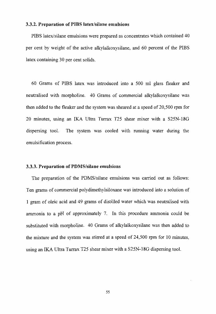
3.3.2. Preparation of PIBS latex/silane emulsions
PIBS latex/silane emulsions were prepared as concentrates which contained 40
per cent by weight of the active alkylalkoxysilane, and 60 percent of the PIBS
latex containing 30 per cent solids.
60 Grams of PIBS latex was introduced into a 500 ml glass fleaker and
neutralised with morpholine. 40 Grams of commercial alkylalkoxysilane was
then added to the fleaker and the system was sheared at a speed of 20,500 rpm for
20 minutes, using an IKA Ultra Turrax T25 shear mixer with a S25N- l 8G
dispersing tool. The system was cooled with running water during the
emulsification process.
3.3.3. Preparation of PDMS/silane emulsions
The preparation of the PDMS/silane emulsions was carried out as follows:
Ten grams of commercial polydimethylsiloxane was introduced into a solution of
1 gram of oleic acid and 49 grams of distilled water which was neutralised with
ammonia to a pH of approximately 7. In this procedure ammonia could be
substituted with morpholine. 40 Grams of alkylalkoxysilane was then added to
the mixture and the system was stirred at a speed of 24,500 rpm for 10 minutes,
using an IKA Ultra Turrax T25 shear mixer with a S25N- l 8G dispersing tool.
55
3.4. T,est procedures
3.4.1. Freeze-thaw stability test
Freeze-thaw resistance tests for the PIBS latex and the novel silane/siloxane
emulsions were carried out according to ASTM D2243 Standard Test Method.
Samples were stored in a test chamber maintained at - l 8°C in such a manner that
free circulation of air was permitted around each container. For a 24 hour freeze
thaw cycle, the test samples were kept in the chamber for 17 hours and then
removed and allowed to stand undisturbed at room temperature for 7 hours,
adjacent to the control samples. The procedure was repeated three times and
each sample was tested in duplicate. After completion of three cycles, the
samples were then observed for any sign of settling and coagulation.
3.4.2. Preparation of test specimens
Concrete was prepared in the laboratory with the following mix proportions (in
kg/m3):
Cement 281
Water 180
Aggregate
Coarse (20 mm) 410
Fine (I 0 mm) 680.
These mix proportions represent a typical medium grade concrete which had
an average compressive strength of 28.5 N/mm2 after 28 days. The mix was cast
56
into slabs of 500x500x45 mm which were cured for 28 days. These concrete
slabs were then cut into cubes with dimensions 50x50x45 mm. The surface of
the concrete cube to be treated was always the same.
Cylindrical cement mortar blocks with dimensions of 75 mm diameter and 30
mm length were prepared in the laboratory according to British Standard (BS
64 77) in which the cement/sand/water ratio was 1: 4.5: 0.6. They were cured at
room temperature for 28 days before testing.
The substrate surface was washed with water using a metal brush, dried in an
oven at 105°C and then allowed to cool to room temperature before impregnation.
One side of the specimen was immersed in the emulsion or solution (Figure 3 .1)
containing different concentrations of alkylalkoxysilane. The time of immersion
was 60 seconds in each case.
lmpregnant
Substrate
0.5 mm I '-------~--__,,..__ __ __,
T 2 mm
_J_
Figure 3 .1. Impregnation of the test sample
57
3.4.3. Beading effect examination
The beading effect was determined according to Scharnberg et al. 39 The
treated substrate was cured for 7 days after impregnation before it was subjected
to water beading examination. About 0.2 ml of tap water was dropped
horizontally onto the test surface with a pipette. After 10 minutes, the water on
the surface was then removed and the contact area of the water droplet and the
surface was evaluated visually and graded according to the following standard:
1 No wetting of the contact area
2 50o/o of the contact area wetted
3 100% of the contact area wetted
4 Part of the water droplet (less than 50%) absorbed
5 50% or more of the water droplet absorbed
6 Water droplet absorbed completely
7 Water droplet completely absorbed in less than 5 minutes.
3.4.4. Measurement of penetration depth
After impregnation with the water repellent liquid, the test samples were
stored for seven days for curing. The depth of penetration was measured by
breaking the impregnated blocks in half and wetting the fractured surfaces with
water. The bright edge (unwetted) of the cross-section was then measured as the
penetration depth of the impregnant.
58
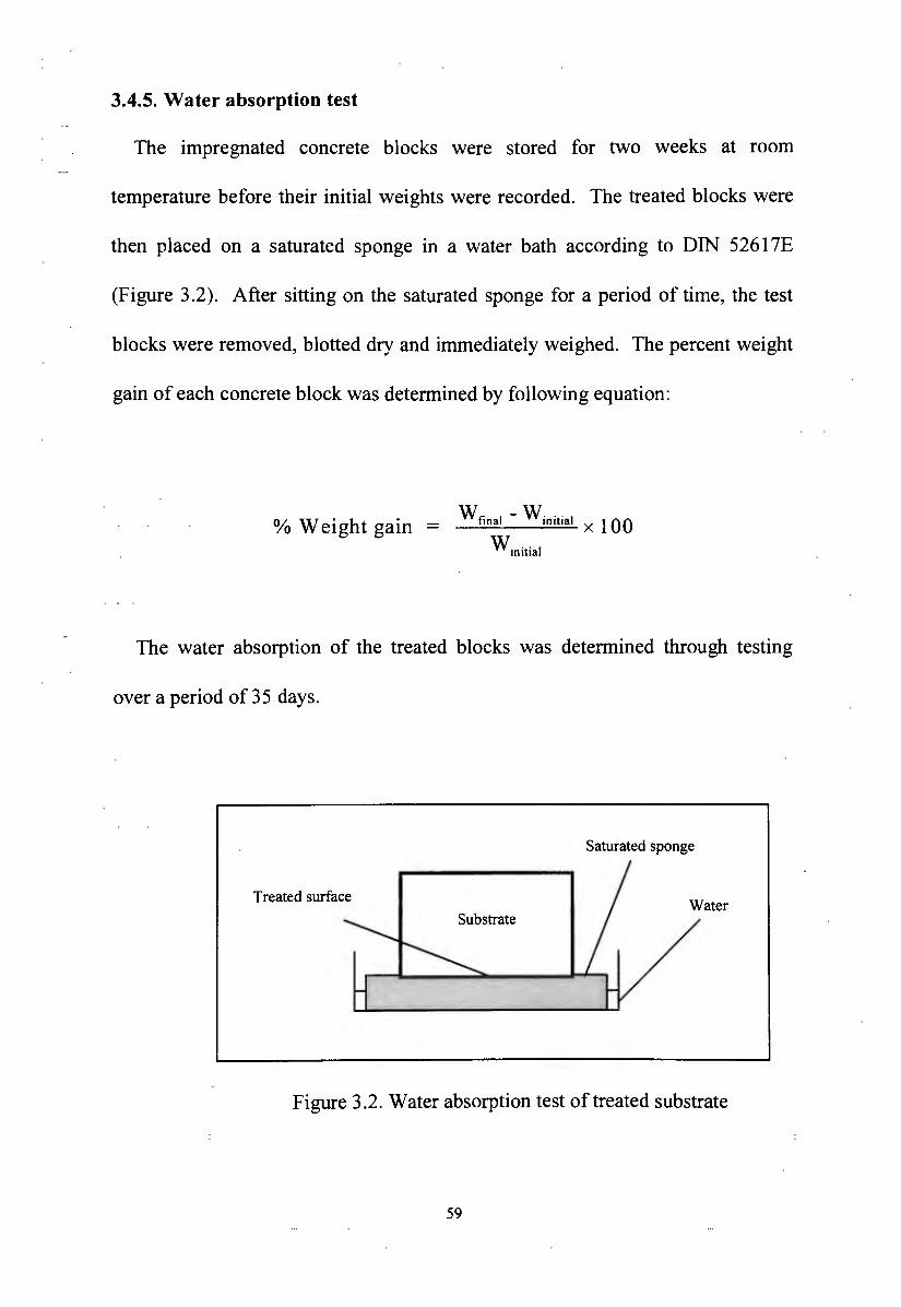
3.4.5. Water absorption test
The impregnated concrete blocks were stored for two weeks at room
temperature before their initial weights were recorded. The treated blocks were
then placed on a saturated sponge in a water bath according to DIN 5261 ?E
(Figure 3 .2). After sitting on the saturated sponge for a period of time, the test
blocks were removed, blotted dry and immediately weighed. The percent weight
gain of each concrete block was determined by following equation:
% Weight gain w final - winitial x 100
winitial
The water absorption of the treated blocks was determined through testing
over a period of 35 days.
Saturated sponge
Treated surface
Substrate
Figure 3.2. Water absorption test of treated substrate
59
3.4.6. Alkali stability test
The test procedure was carried out using a similar procedure to the water
absorption test. The treated blocks were placed on a saturated sponge in a water
bath containing 0.1 M KOH solution. The percent weight gain of each block was
then determined through testing over a period of 3 5 days.
3.4.7. Chloride ion resistance test
One side of a concrete block of dimensions I OOx I OOx 130 mm was immersed
in the silane solutions or silane/siloxane emulsions for 60 seconds. These
specimens were then cured for 28 days. Four sides of the block were then sealed
with epoxy coating to prevent test solution entering the block from these sides.
The blocks were placed in a trough containing 3% NaCl solution so that they
were standing in 1.5 cm solution on the treated side for 35 days. The concrete
blocks were removed from the solution and kept in laboratory conditions for one
week. To determine the chloride content and its change with time in the
controlled environment, cylindrical core specimens of 50 mm in diameter were
taken by drilling downwards perpendicular from the centre of the treated surface
to the opposite untreated surface. The cylindrical core specimen was cut into
discs at a depth of 2,4,6,8, 10 cm below the treated surface. The concrete disc
was then crushed into fine powder with a ring mill. One gram of the concrete
powder was mixed with 100 ml of deionised water and the chloride content in the
solution was determined using the chloride electrode.
60
3.4.8. Efflorescence resistance test
The test procedure was carried out using a similar procedure to the alkali
stability test. The treated concrete blocks were placed with the untreated surface
downward at a depth of 15 mm in a trough containing 1 Oo/o aqueous sodium
sulphate solution so that they were standing at 0.5 mm above the bottom of the
trough. After 14 days, the test samples were examined visually for any sign of
efflorescence on the treated surface.
61
CHAPTER FOUR
Siloxanes for silane/siloxane emulsions and the preparation of
polyisobutylsiloxane latex
4.1. The use of siloxane for the preparation of novel emulsions
Silanes are known to be difficult molecules from which to achieve stable
emulsions. This is due to their polar/non-polar nature and their low viscosity. It
is possible to produce silane emulsions with non-ionic surfactant as the emulsifier
as reported for instance by De Pasquale and Wilson.29 The level of surfactant
necessary to achieve a stable emulsion produces a wetting effect on treated
concrete substrates. Investigation of a range of non-ionic surfactants with a
variety of silanes in the present study confirmed the difficulty of achieving a
satisfactorily high concentration silane emulsion in terms of stability and
performance.
The polarity and viscosity of the orgamc phase of the emulsion may be
adjusted by the addition of oligomeric silanes. This was investigated in the
present study by the use of mixtures of silanes and octyl/methyl methoxysiloxane
(BS 1268). The use of such silane/oligomeric silane mixtures as the oil phase for
the emulsion did not produce success in terms of the parameters of stability and
performance for high concentration silane emulsions. The use of amine soap
62
surfactants within this system also did not provide satisfactory emulsions.
Therefore, in order to develop a novel silane/siloxane emulsion, it was necessary
to prepare a suitable polysiloxane to add to the base silane and surfactant. This
can be achieved by using a commercial siloxane or by polymerisation of a
monomeric silane.
The use of commercial silicone fluids to prepare novel silane/siloxane
emulsions has been investigated in this study with the intention of solving the
stability problem related to the viscosity of the oil phase and to simplify the
preparation process. Silicone fluids containing large alkyl substituents are not
commercially available and thus, commercial polydimethysiloxanes (PDMS)
with molecular weights in the range of 3 780 to 28,000 have been used. In order
to minimise the unfavourable effect of the methyl group on the performance of
the PDMS/silane emulsions, the concentration of the PDMS was minimised and
amine soap was used as an emulsifier. It was found that a commercial PDMS
with trimethylsiloxy termination having a molecular weight of 13,650 was the
preferred siloxane for the preparation of PDMS/silane emulsions with the amine
soap as surfactant.
Consideration of the parameters of the target silane emulsion required that the
desired polysiloxane obtained by polymerisation for use with the silane as the oil
phase should be alkali stable. In general, methyl silicone polymers are not alkali
63
stable (see Chapter 6). Therefore, the use of a methyl silane as the monomer for
polymerisation was not a satisfactory choice. The choice of silane rested with
propylsilane, butylsilane or octylsilane. The propylsilicone polymer would not
achieve comparable alkali stability to those from butyl or octylsilanes so it was
discarded as a choice. This left butyl or octyl as the alkyl substituent on silicone.
It was considered that the octyl substituent may be too bulky and hydrolysis of
the esters of octylsilane are known to be difficult. Therefore, isobutyl was chosen
as the alkyl group. The methyl ester was chosen due to the ease of hydrolysis in
the acidic conditions of the polymerisation reaction. Isobutyltrimethoxysilane
was therefore chosen as the monomeric silane to investigate for polymerisation to
a polysiloxane additive (PIBS) possibly suitable for preparation of the
silane/siloxane emulsion.
It was found in this study that stable silane/siloxane emulsions could be
prepared from a polyisobutylsiloxane (PIBS) latex and an alkylalkoxysilane. The
use of PIBS latex for the development of novel silane/siloxane emulsions has
several advantages. The latex produced from the emulsion polymerisation of
IBTMS was employed directly for the preparation of silane/siloxane emulsions
with no more surfactant required. The particle size of the latex particles and the
molecular weight of the PIBS was definable under effective temperature control
and suitable concentration of surfactant. This would contribute to the film
thickness during the application of the silane/siloxane emulsion on the concrete
64
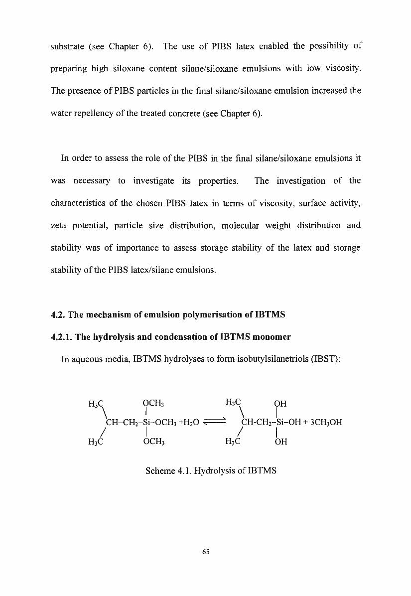
substrate (see Chapter 6). The use of PIBS latex enabled the possibility of
preparing high siloxane content silane/siloxane emulsions with low viscosity.
The presence of PIBS particles in the final silane/siloxane emulsion increased the
water repellency of the treated concrete (see Chapter 6).
In order to assess the role of the PIBS in the final silane/siloxane emulsions it
was necessary to investigate its properties. The investigation of the
characteristics of the chosen PIBS latex in terms of viscosity, surface activity,
zeta potential, particle size distribution, molecular weight distribution and
stability was of importance to assess storage stability of the latex and storage
stability of the PIBS latex/silane emulsions.
4.2. The mechanism of emulsion polymerisation of IBTMS
4.2.1. The hydrolysis and condensation of IBTMS monomer
In aqueous media, IBTMS hydrolyses to form isobutylsilanetriols (IBST):
Scheme 4.1. Hydrolysis oflBTMS
65
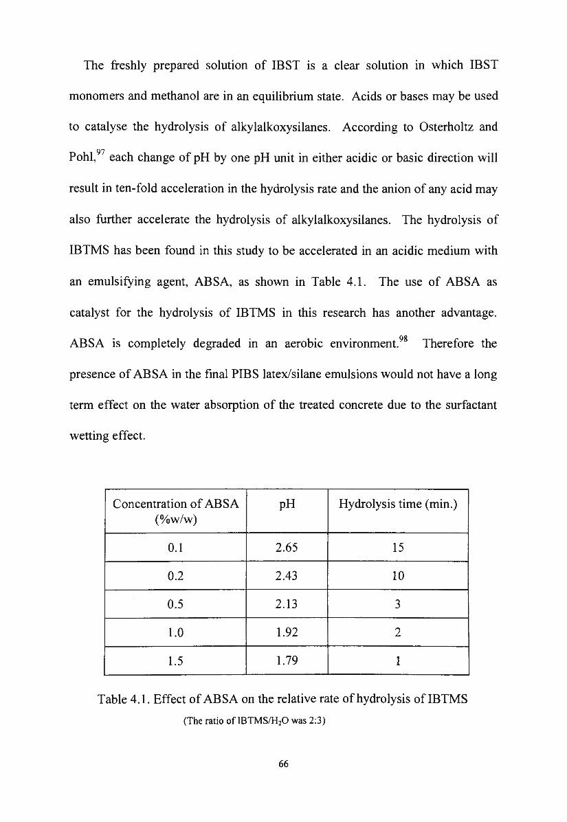
The freshly prepared solution of IBST is a clear solution in which IBST
monomers and methanol are in an equilibrium state. Acids or bases may be used
to catalyse the hydrolysis of alkylalkoxysilanes. According to Osterholtz and
Pohl, 97 each change of pH by one pH unit in either acidic or basic direction will
result in ten-fold acceleration in the hydrolysis rate and the anion of any acid may
also further accelerate the hydrolysis of alkylalkoxysilanes. The hydrolysis of
IBTMS has been found in this study to be accelerated in an acidic medium with
an emulsifying agent, ABSA, as shown in Table 4.1. The use of ABSA as
catalyst for the hydrolysis of IBTMS in this research has another advantage.
ABSA is completely degraded in an aerobic environment.98 Therefore the
presence of ABSA in the final PIBS latex/silane emulsions would not have a long
term effect on the water absorption of the treated concrete due to the surfactant
wetting effect.
Concentration of ABSA pH Hydrolysis time (min.) (o/ow/w)
0.1 2.65 15
0.2 2.43 10
0.5 2.13 3
1.0 1.92 2
1.5 1.79 1
Table 4.1. Effect of ABSA on the relative rate of hydrolysis ofIBTMS
(The ratio of IBTMS/H20 was 2:3)
66
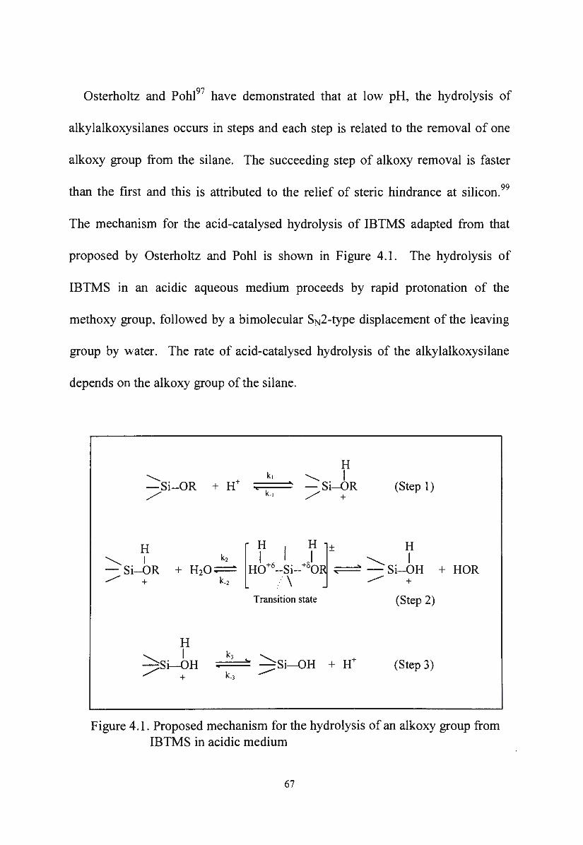
Osterholtz and Pohl97 have demonstrated that at low pH, the hydrolysis of
alkylalkoxysilanes occurs in steps and each step is related to the removal of one
alkoxy group from the silane. The succeeding step of alkoxy removal is faster
than the first and this is attributed to the relief of steric hindrance at silicon. 99
The mechanism for the acid-catalysed hydrolysis of IBTMS adapted from that
proposed by Osterholtz and Pohl is shown in Figure 4.1. The hydrolysis of
IBTMS in an acidic aqueous medium proceeds by rapid protonation of the
methoxy group, followed by a bimolecular SN2-type displacement of the leaving
group by water. The rate of acid-catalysed hydrolysis of the alkylalkoxysilane
depends on the alkoxy group of the silane.
............. -Si-OR + H+ /
H '-...... I - Si-OR _,,/' +
H I
)si-OH + k_3
H ..........._ I - Si-OR / +
(Step 1) k.1
[
H I H1+ H I I - I H0+8--Si--+oo ~ '---..Si-OH
/ \ -- + Transition state (Step 2)
(Step 3)
+HOR
Figure 4.1. Proposed mechanism for the hydrolysis of an alkoxy group from IBTMS in acidic medium
67
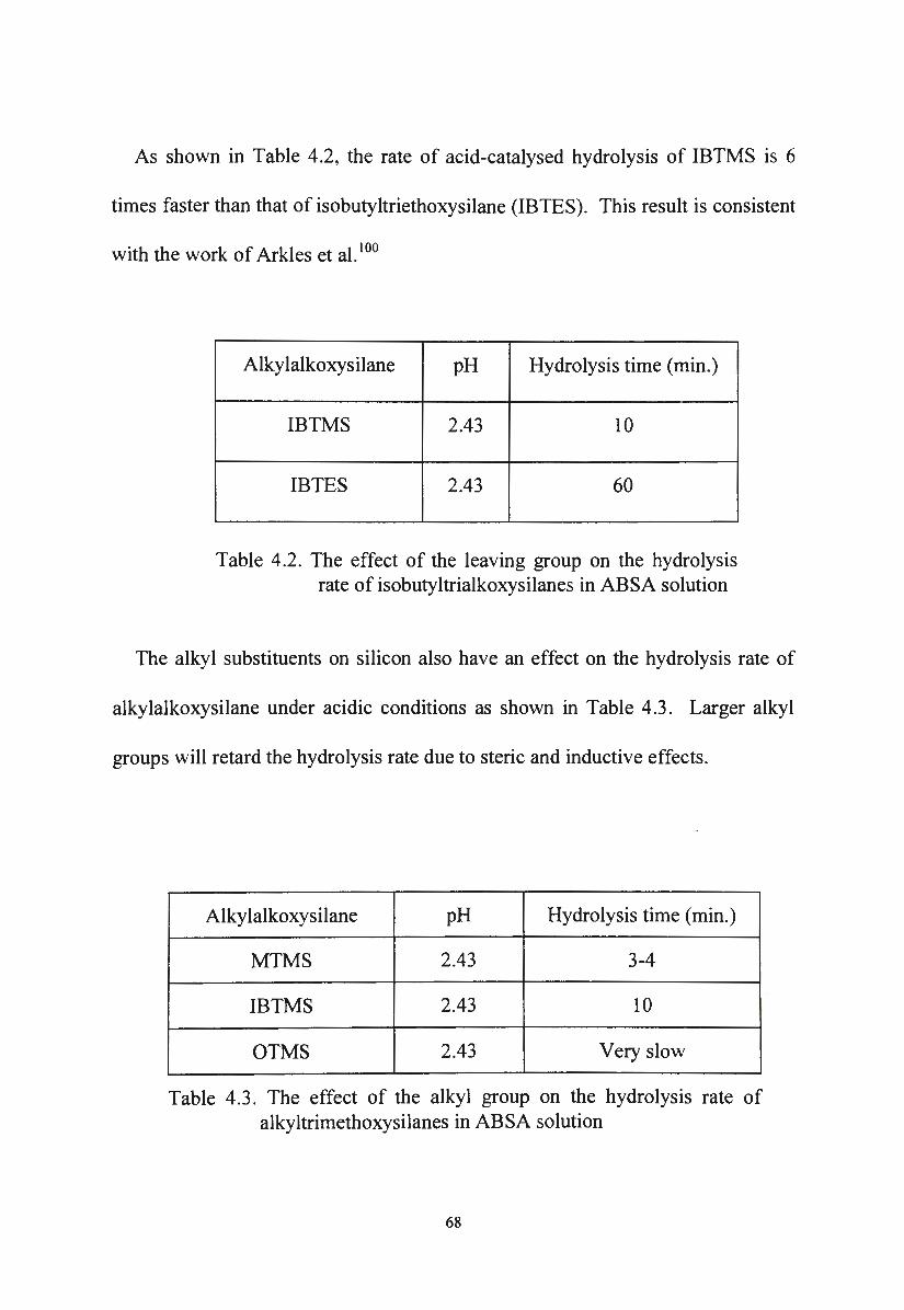
As shown in Table 4.2, the rate of acid-catalysed hydrolysis of IBTMS is 6
times faster than that of isobutyltriethoxysilane (IBTES). This result is consistent
with the work of Arkles et al. 100
Alky lalkoxysilane pH Hydrolysis time (min.)
IBTMS 2.43 10
IBTES 2.43 60
Table 4.2. The effect of the leaving group on the hydrolysis rate of isobutyltrialkoxysilanes in ABSA solution
The alkyl substituents on silicon also have an effect on the hydrolysis rate of
alkylalkoxysilane under acidic conditions as shown in Table 4.3. Larger alkyl
groups will retard the hydrolysis rate due to steric and inductive effects.
Alky lalkoxysilane pH Hydrolysis time (min.)
MTMS 2.43 3-4
IBTMS 2.43 10
OTMS 2.43 Very slow
Table 4.3. The effect of the alkyl group on the hydrolysis rate of alkyltrimethoxysilanes in ABSA solution
68
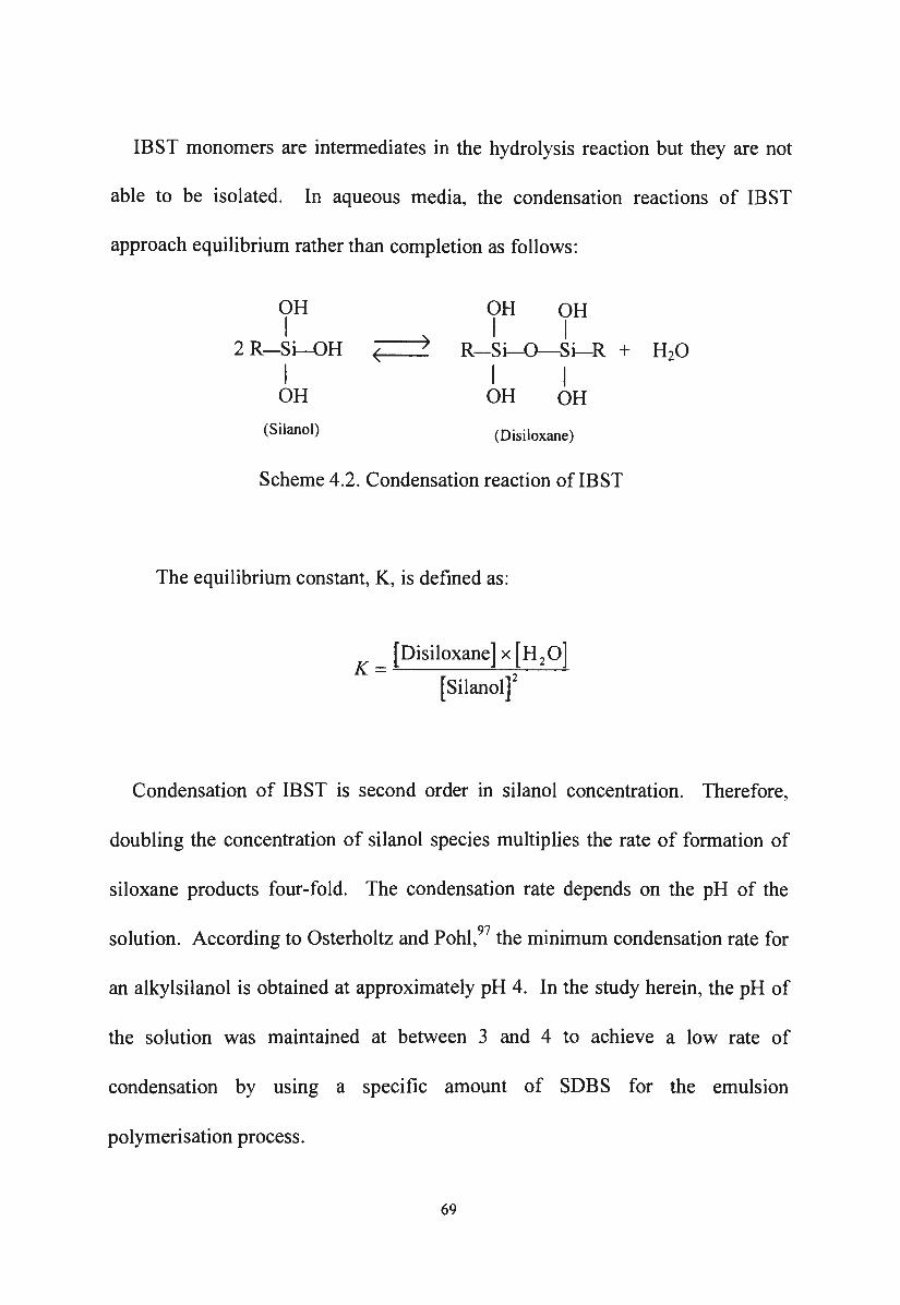
IBST monomers are intermediates in the hydrolysis reaction but they are not
able to be isolated. In aqueous media, the condensation reactions of IBST
approach equilibrium rather than completion as follows:
OH OH OH I
2 R-Si-OH -< __ > I I
R-Si-0--Si-R + H20 I I I OH OH OH
(Silano!) (Disiloxane)
Scheme 4.2. Condensation reaction of IBST
The equilibrium constant, K, is defined as:
K = [Disiloxane] x [H 20]
[Silanol]2
Condensation of IBST is second order in silanol concentration. Therefore,
doubling the concentration of silanol species multiplies the rate of formation of
siloxane products four-fold. The condensation rate depends on the pH of the
solution. According to Osterholtz and Pohl, 97 the minimum condensation rate for
an alkylsilanol is obtained at approximately pH 4. In the study herein, the pH of
the solution was maintained at between 3 and 4 to achieve a low rate of
condensation by usmg a specific amount of SOBS for the emulsion
polymerisation process.
69
Both the hydrolysis reactions and condensation reactions of alkylalkoxysilanes
are reversible. The condensation of silanols proceeds more rapidly at higher
temperatures. Therefore, the hydrolysis of IBTMS was undertaken at room
temperature. Alcohol produced from the hydrolysis reaction stabilises the
silanols in the solution. The removal of methanol from the IBTMS emulsion
polymerisation process was undertaken slowly at a moderate temperature. The
slow evaporation of methanol in the process and the maintenance of the pH
between 3 and 4 prolongs the lifetime of the silanol monomers in the solution.
This would allow the silanol monomers enough time to enter the SDBS micelles
before they are condensed and reduce the number of silanol monomers
undergoing condensation in the bulk solution. IBTMS was chosen as the silane
monomer in the emulsion polymerisation reaction for several reasons. It is easily
hydrolysed under acidic conditions compared to OTMS. The removal of
methanol during the emulsion polymerisation of IBTMS can be carried out at a
low temperature under atmospheric pressure. Further, the final product is a PIBS
latex containing the isobutyl group as the alkyl group which contributes to the
alkali stability after application of the PIBS latex/silane emulsion impregnants (as
discussed in 6.5). Also the IBTMS is commercially available.
The polymer in the latex particles is a cross-linked polyisobutylsiloxane
(PIBS) resin with terminal hydroxyl groups as shown in the 29Si NMR spectrum
of PIBS (Figure 4.2). In this figure, the sharp peak resonating at -42.32 ppm may
70
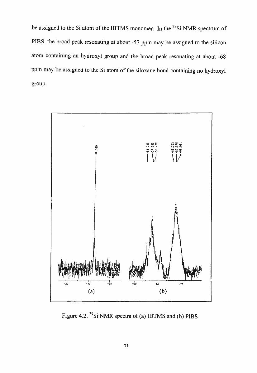
be assigned to the Si atom of the IBTMS monomer. In the 29Si NMR spectrum of
PIBS, the broad peak resonating at about -57 ppm may be assigned to the silicon
atom containing an hydroxyl group and the broad peak resonating at about -68
ppm may be assigned to the Si atom of the siloxane bond containing no hydroxyl
group.
CD "' C7' ..,.., _
.... <7'"' <1' ~ <7'
"' "' CJ • .., ..., 0
"' <D - CD ': "' - c:> ..., ..., ...,
\ll "' .. . . I \/ .
(a) (b)
Figure 4.2. 29Si NMR spectra of (a) IBTMS and (b) PIBS
71

The 29Si NMR assignment of IBTMS and PIBS is summarised in Table 4.4 .
These assignments are consistent with the work of Nishiyama and Horie 101 on the
hydrolysis and condensation of y-methacryloxypropyltrimethoxysilane and
justified by the 29Si CP/MAS chemical shift data of several kinds of Si
compounds studied by Sindorf and MacieI. 102
Assignment 8 (ppm)
I CH2 I
CH30-Si-OCH3 -42.325
I OCH3
OH
I -CH2-Si-O-
I -57.892
0
I
I 0 I
-CH2-Si-O- -67.576
I 0 I
Table 4.4. Assignment of 29Si NMR spectra ofIBTMS and PIBS
72
4.2.2. The role of the surfactant in the emulsion polymerisation of IBTMS
In the emulsion polymerisation of IBTMS, the choice of surfactant is
considered to be a very important factor. The surfactant must have the ability to
stabilise polymer particles in the final polyisobutylsiloxane (PIBS) latex and not
interfere adversely with the condensation of silanol monomer in the emulsion
polymerisation process. Since the residual surfactant will remain in the final
PIBS latex recovered after emulsion polymerisation, it must impart no adverse
properties to the latex.
The maJor characteristic of a surfactant is that it appears at a higher
concentration at the surface than in the bulk of a liquid and this phenomenon is
known as adsorption. The adsorption of the surfactant at the surface is a
consequence of its molecular structure. A surfactant contains both a hydrophilic
and a hydrophobic group. The hydrophilic group makes the surfactant soluble in
the aqueous phase whilst the hydrophobic group has only a slight affinity for
water. In aqueous solution, the surfactant migrates to the water-air interface,
resulting in a lowering of the surface tension of the water. If the external phase is
organic, the hydrophobic portion of the surfactant is very compatible with the
external phase and perhaps even soluble in it, and the tendency to migrate to the
water-organic interface is increased. This results in a lowering of the interfacial
tension between the water and organic phases. It is not likely that all the
surfactant molecules will be adsorbed at the surface when the concentration of
73
surfactant increases; the additional surfactant molecules remain in the bulk of the
solution and their hydrophobic heads will still be expelled from the water. This
expulsion is opposed by the hydrophilic groups and the end result is that the
excess surfactant molecules aggregate together to form small colloidal clusters
called micelles. The concentration of surfactant at which micelles start to form is
called the critical micelle concentration (CMC). The CMC varies with different
surfactants and its value is usually in the 0.08 to 0.30% range. In a dilute solution
of 0.5 to 2.0o/o of surfactant, there is an equilibrium between micelles and single
surfactant molecules in the aqueous phase. The number of single surfactant
molecules in the aqueous phase depends on the CMC. According to McCoy, 103
surfactants with a low CMC give fewer single surfactant molecules than those
with a high CMC. The CMC of surfactants in solution is related to the
hydrocarbon chain of the molecule and can be defined in an empirical
relationship 104 as follows:
tiG w tiG h K log10 Ckte= m +nJ m-)+log10+ (4.1)
2.3RT 2.3RT 2.3RT
where LlGm h is the free energy term favouring micellisation, LlGm w is the free
energy term opposing micelle formation, K is a constant, and nc is the number of
carbon atoms in the hydrocarbon tail. Equation (4.1) shows that the CMC
decreases as the number of carbons in the hydrophobic chain increases. In
aqueous media, the CMC of ionic surfactants is approximately halved by the
74
addition of each CH2 group in their hydrocarbon chain. 105 The nature of the
charged hydrophilic group of ionic surfactants has little effect on their CMC. 106
Apart from the chemical constitution, the micellisation of a surfactant in an
aqueous medium also depends on many other factors which can in tum influence
the solubilising ability of the surfactant. It has been shown that the CMC of most
ionic surfactants passes through a minimum as the temperature is varied from
about 0°C to 70°C. 107 The addition of electrolytes such as alcohols, amines or
mercaptans to the aqueous phase also causes the CMC to fall. 108 The size of the
micelle is usually measured by the aggregation number which is the number of
surfactant molecules going to make up the aggregate micelle. The size of
micelles formed by non-ionic surfactants is very large compared to those from
anionic or cationic surfactants. 106 Several different micelle structures are
possible, but at relatively dilute concentration (1-2%) micelles are spherical 109
and are 20-100 nm in diameter. 110 Each micelle contains about 50-100 surfactant
molecules. 111 In spherical micelles, the hydrocarbon ends of the surfactant
molecules orient towards the interior of the micelle and their ionic ends orient
outward, towards the water.
The use of SDBS in the emulsion polymerisation of IBTMS, has some
advantages. Firstly, the size of the SDBS micelles is not very large compared to
those from nonionic surfactants and this will not produce large polymer particles.
75
Secondly, the CMC of SDBS is relatively low due to its long hydrophobic carbon
chain. Therefore, in aqueous media, the number of micelles is higher than the
number of single surfactant molecules in the solution. Thirdly, SDBS is
completely ionised in aqueous solution and the free sulphonic acid is water
soluble so the solubility of SDBS is not affected106 at low pH due to the presence
of ABSA which was used as catalyst for the hydrolysis of IBTMS.
SDBS plays a significant role in the emulsion polymerisation process. It
increases the amount of the silanol monomers taken into the water phase owing to
solubilisation in micelles. It also emulsifies the silanol monomers into fine stable
droplets. Once the polymerisation process has begun the SDBS protects the latex
particles against coagulation during and after the emulsion polymerisation
process. The number of SDBS micelles and their size depends on the amount of
surfactant used compared to the amount of monomer. Larger amounts of
surfactant will yield a larger number of small size micelles. The quantity of
micellar SDBS also determines the number of polymer particles formed. The
number of latex particles formed and the rate of the polymerisation reaction
depends on the concentration of micellar surfactants. 111 When higher
concentrations of SDBS are used, small latex particles are formed (; 4.2.2) but
the residual surfactant remains in the PIBS latex and will have a wetting effect on
the treated concrete on application of the final emulsion. If the concentration of
SDBS is low, the amount of surfactant may be insufficient to cover and stabilise
76
the ever growing surface of the latex particle. Consequently the latex is not
stable and the addition of more surfactant is required for the production of stable
PIBS latex/silane emulsions in the next process. The pH of the system depends
on the concentration of SDBS. The pH of the system was maintained at 3-4 in
order to control the rate of the condensation of silanol 112 and to assure the
polycondensation of the silanol monomers mainly within the SDBS micelles.
4.2.3. The mechanism of the emulsion polymerisation process
Emulsion polymerisation of IBTMS is heterogeneous reaction and the
mechanism of the process can be explained by the general theory of the
mechanism of emulsion polymerisation developed by Harkins. 113
In a dilute solution of SDBS above its CMC, SDBS micelles are formed. A
small portion of the IBST monomer enters the interior hydrocarbon section of the
micelles. This action is caused by the hydrophobic interaction between the tail of
the surfactant molecule and the hydrocarbon group of the silanol monomers. A
larger portion of the silanol monomer is dispersed as small droplets whose sizes
depend on the intensity of agitation. These monomer droplets are stabilised in
the water by the adsorption of surfactant molecules on the surface and they are
quite a bit larger than the monomer swollen micelles. Under the effect of
temperature and agitation, methanol slowly evaporates from the bulk solution.
The condensation polymerisation of the IBST monomers takes place
77
simultaneously and almost exclusively in the interior of the micelles as the
methanol evaporates. The micelles are favoured as reaction sites 114 because of
their high monomer concentration compared to the IBST monomer in the solution
and their high surface-to-volume ratio compared to the IBST monomer droplets .
As polymerisation proceeds, the micelles grow by the addition of silanol
monomer molecules from the aqueous phase whose monomer concentration is
replenished by the diffusion of IBST monomer molecules from the IBST
monomer droplets. The activated micelles become polymer particles with
surfactant molecules adsorbed on their surface. As the polymer particles grow,
the monomer droplets lose their IBST monom,er and eventually disappear. A
simplified schematic representation of the emulsion polymerisation system is
shown in Figure 4.3. The separate parts of this figure relate to the various stages
of the emulsion polymerisation system from initiation up to complete conversion.
The system initially consists of three types of particles; namely silanol IBST
monomer droplets, micelles free of IBST monomers, and micelles containing
IBST monomers in which the condensation reaction is about to begin. At this
stage, the surface free energy of the aqueous phase-air interface is low due to the
adsorption of the surfactant molecules. The monomer droplets are very large
relative to the micelles and they tend to coalesce if the system is not agitated.
78
At stage 1, the system is in the initial stages of the condensation reaction of
silanol monomers. Some siloxane oligomers are now formed in the interior of
the micelles.
At stage 2, all the silanol monomer-swollen micelles have disappeared. The
number of surfactant molecules adsorbed on the monomer droplets has fallen,
and so too has the amount of dissolved SDBS molecules. The size of the latent
latex particles is increasing at the expense of silanol monomer droplets which
have become smaller and fewer in number. The surface free energy of the
aqueous phase-air interface has increased, the number of reaction loci is constant,
and so too, therefore, is the polymerisation rate.
At stage 3, the silanol monomer droplets have disappeared and the system
comprises polysiloxane particles which are dispersed in the aqueous phase and
some "free" IBST monomers which later condense outside the micelles to form
latex coagulum.
At the completion of the emulsion polymerisation process, the system
comprises polyisobutylsiloxane (PIBS) particles which are dispersed in the
aqueous phase. These PIBS particles are stabilised by the surfactant molecules of
the original micelles. Latex coagulum is also present in the system therefore, the
purification of the latex system is necessary.
79
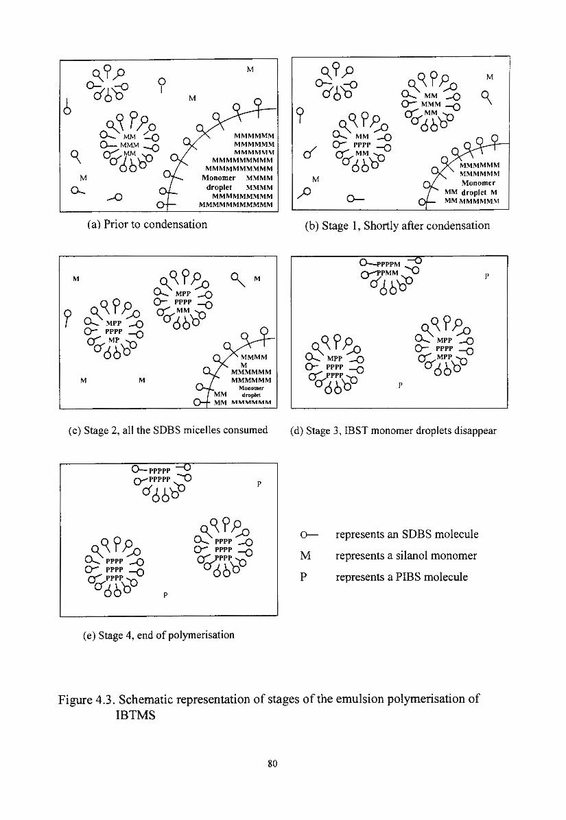
M °'? ;:> 0
°26~ I
6 M
°' M
0-
M
M
~!~Ji MMMMMM 0-MMM -0 MMMMMM
Oif66'00 MMMMMM
MMMMMMMMM MMMMMMMMMM
Monomer MMMM droplet MMMM
-0 MMMMMMMMM MMMMMMMMMMM
(a) Prior to condensation
M
~~?J;o °"M 0...... MPP -Q 0- pppp -0
Dif66'&
Monomer droplet
MM MMMMMM
( c) Stage 2, all the SDBS micelles consumed
0- ppppp --()
Q-PPPPP -0
dc!Jb~
p
(e) Stage 4, end of polymerisation
p
°'? ,P ~~? J;o M
°d6~ °' 0...... MM -Q 0- MMM -0
9 ~~? J;o Dif66'& 0...... MM -Q
cl 0- pppp -0
Dif66'& M Monomer
,)) MM droplet M 0- MMMMMMMM
(b) Stage 1, Shortly after condensation
p
p
(d) Stage 3, IBST monomer droplets disappear
o- represents an SDBS molecule
M represents a silanol monomer
P represents a PIBS molecule
Figure 4.3. Schematic representation of stages of the emulsion polymerisation of IBTMS
80
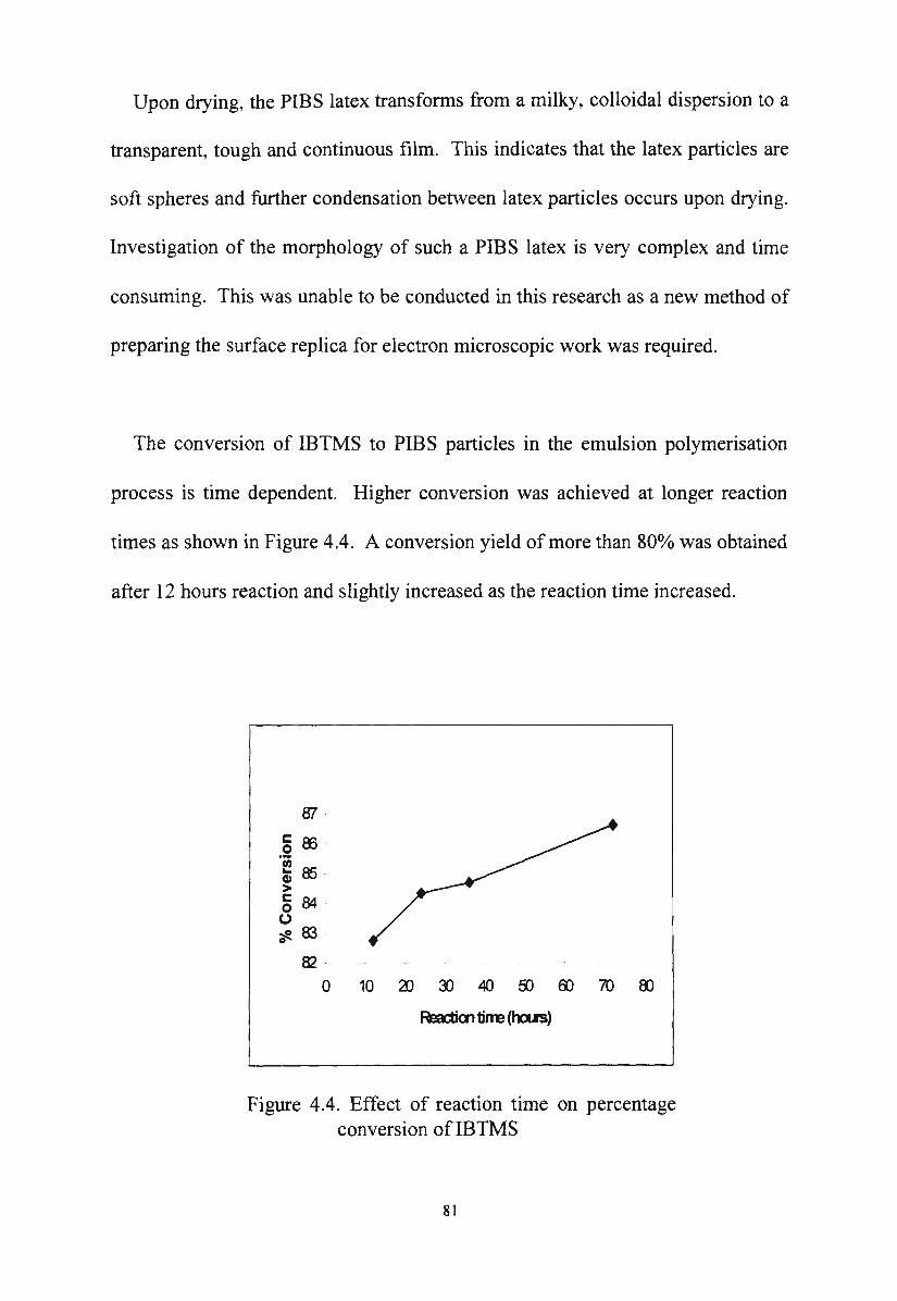
Upon drying, the PIBS latex transforms from a milky, colloidal dispersion to a
transparent, tough and continuous film. This indicates that the latex particles are
soft spheres and further condensation between latex particles occurs upon drying.
Investigation of the morphology of such a PIBS latex is very complex and time
consuming. This was unable to be conducted in this research as a new method of
preparing the surface replica for electron microscopic work was required.
The conversion of IBTMS to PIBS particles in the emulsion polymerisation
process is time dependent. Higher conversion was achieved at longer reaction
times as shown in Figure 4.4. A conversion yield of more than 80o/o was obtained
after 12 hours reaction and slightly increased as the reaction time increased.
ff1
.2 ffi
~ 8.5 > § 84 0 ~ 83 0
82 -
0 10 al :Il 40 &> 00 70 00
Fm:tim tirm (Inn)
Figure 4.4. Effect of reaction time on percentage conversion of IBTMS
81
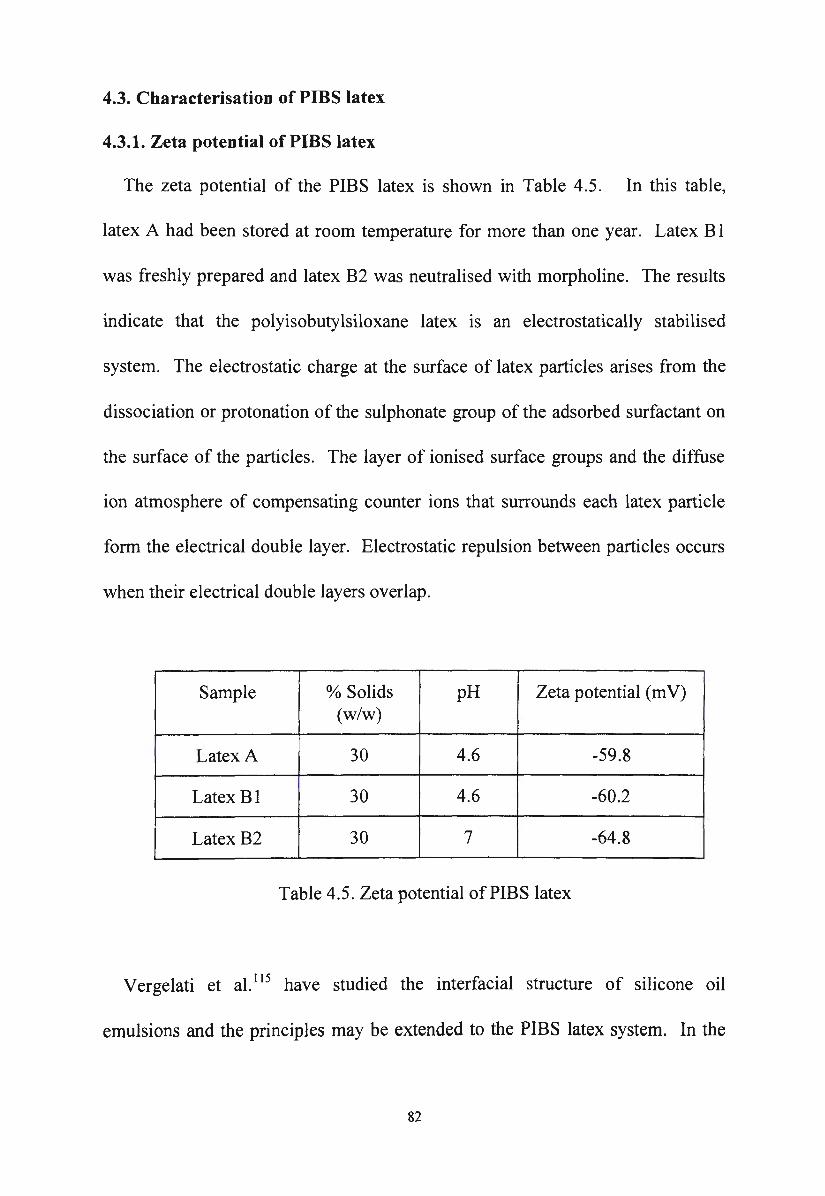
4.3. Characterisation of PIBS latex
4.3.1. Zeta potential of PIBS latex
The zeta potential of the PIBS latex is shown in Table 4.5. In this table,
latex A had been stored at room temperature for more than one year. Latex B I
was freshly prepared and latex B2 was neutralised with morpholine. The results
indicate that the polyisobutylsiloxane latex is an electrostatically stabilised
system. The electrostatic charge at the surface of latex particles arises from the
dissociation or protonation of the sulphonate group of the adsorbed surfactant on
the surface of the particles. The layer of ionised surface groups and the diffuse
ion atmosphere of compensating counter ions that surrounds each latex particle
form the electrical double layer. Electrostatic repulsion between particles occurs
when their electrical double layers overlap.
:
Sample % Solids pH Zeta potential (m V)
' (w/w)
Latex A 30 4.6 -59.8
Latex Bl 30 4.6 -60.2
Latex B2 30 7 -64.8
Table 4.5. Zeta potential of PIBS latex
Vergelati et al. 115 have studied the interfacial structure of silicone oil
emulsions and the principles may be extended to the PIBS latex system. In the
82
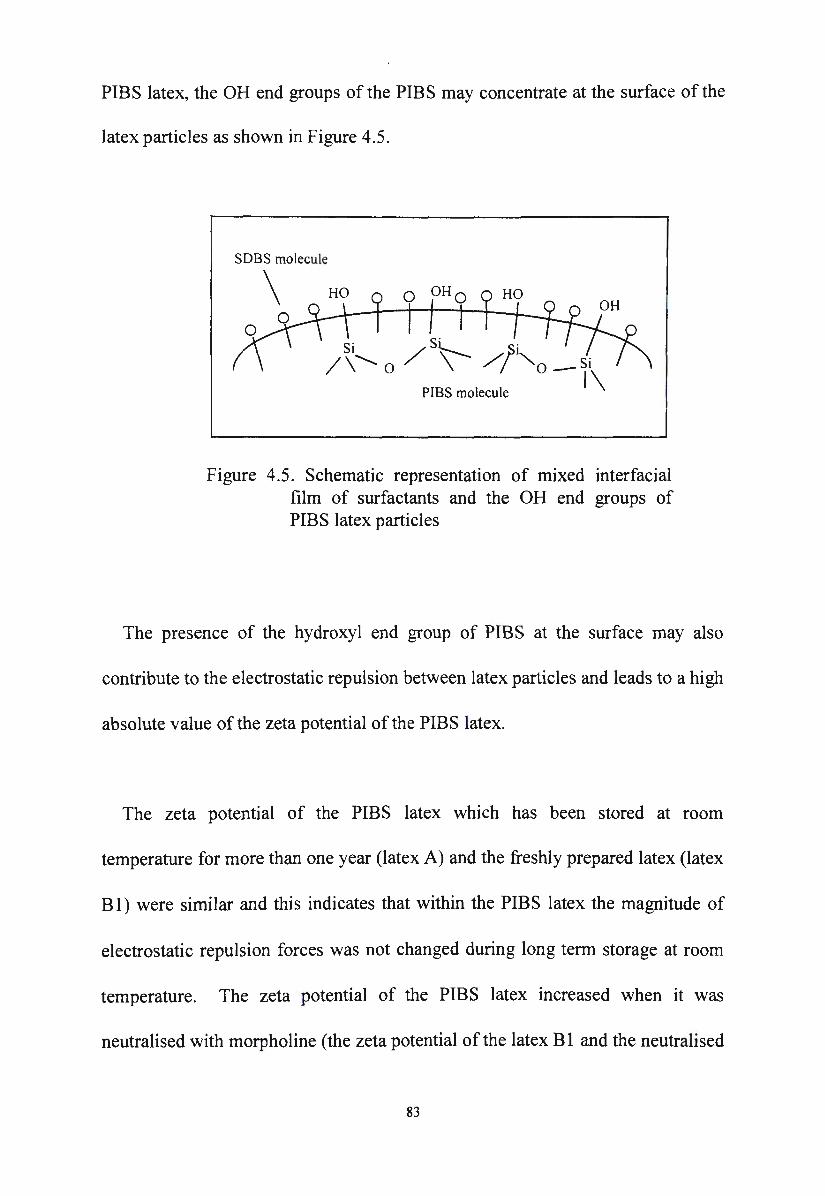
PIBS latex, the OH end groups of the PIBS may concentrate at the surface of the
latex particles as shown in Figure 4.5.
SOBS molecule
\ 0 OHO HO
Si /S~ ,$i /\"- o \ /; "-o-ji
PIBS molecule \
Figure 4.5. Schematic representation of mixed interfacial film of surfactants and the OH end groups of PIBS latex particles
The presence of the hydroxyl end group of PIBS at the surface may also
contribute to the electrostatic repulsion between latex particles and leads to a high
absolute value of the zeta potential of the PIBS latex.
The zeta potential of the PIBS latex which has been stored at room
temperature for more than one year (latex A) and the freshly prepared latex (latex
B 1) were similar and this indicates that within the PIBS latex the magnitude of
electrostatic repulsion forces was not changed during long term storage at room
temperature. The zeta potential of the PIBS latex increased when it was
neutralised with morpholine (the zeta potential of the latex B 1 and the neutralised
83
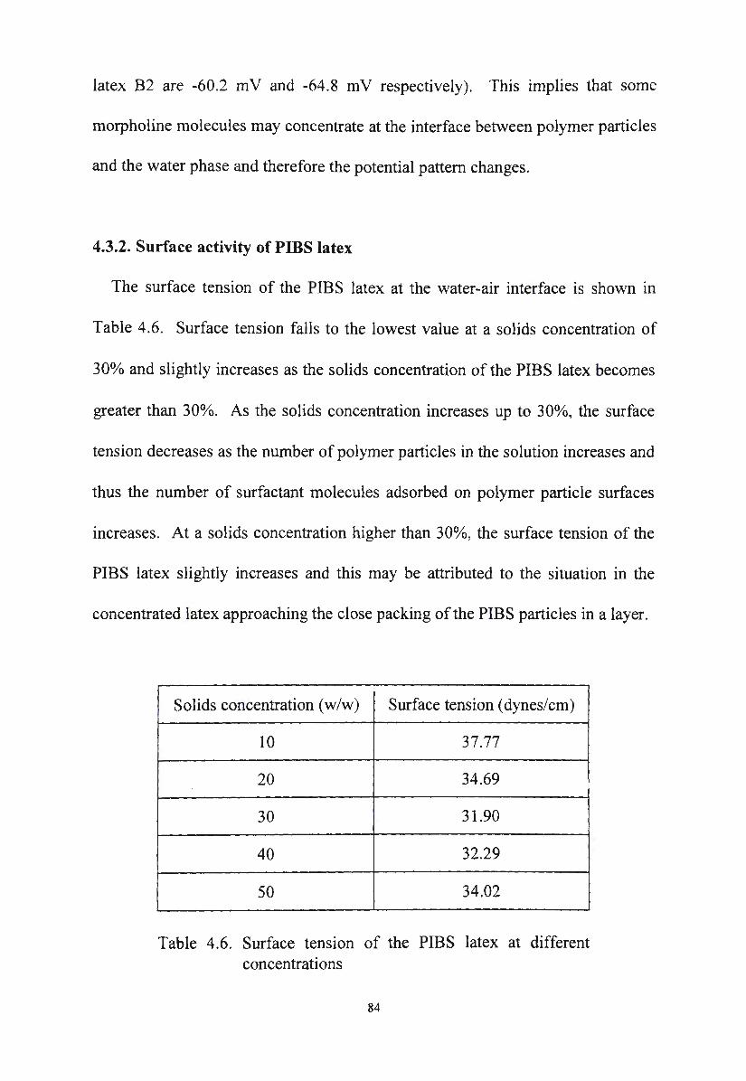
latex B2 are -60.2 m V and -64.8 m V respectively). This implies that some
morpholine molecules may concentrate at the interface between polymer particles
and the water phase and therefore the potential pattern changes.
4.3.2. Surface activity of PIBS latex
The surface tension of the PIBS latex at the water-air interface is shown in
Table 4.6. Surface tension falls to the lowest value at a solids concentration of
30o/o and slightly increases as the solids concentration of the PIBS latex becomes
greater than 30%. As the solids concentration increases up to 30%, the surface
tension decreases as the number of polymer particles in the solution increases and
thus the number of surfactant molecules adsorbed on polymer particle surfaces
increases. At a solids concentration higher than 30%, the surface tension of the
PIBS latex slightly increases and this may be attributed to the situation in the
concentrated latex approaching the close packing of the PIBS particles in a layer.
Solids concentration (w/w) Surface tension ( dynes/cm)
10 37.77
20 34.69
30 31.90
40 32.29 I
50 34.02
Table 4.6. Surface tension of the PIBS latex at different concentrations
84
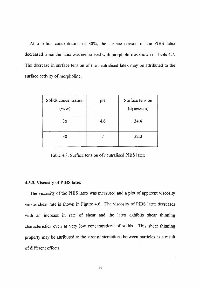
At a solids concentration of 30o/o, the surface tension of the PIBS latex
decreased when the latex was neutralised with morpholine as shown in Table 4. 7.
The decrease in surface tension of the neutralised latex may be attributed to the
surface activity of morpholine.
Solids concentration pH Surface tension
(w/w) (dynes/cm)
30 4.6 34.4
30 7 32.0
Table 4.7. Surface tension of neutralised PIBS latex
4.3.3. Viscosity of PIBS latex
The viscosity of the PIBS latex was measured and a plot of apparent viscosity
versus shear rate is shown in Figure 4.6. The viscosity of PIBS latex decreases
with an increase in rate of shear and the latex exhibits shear thinning
characteristics even at very low concentrations of solids. This shear thinning
property may be attributed to the strong interactions between particles as a result
of different effects.
85
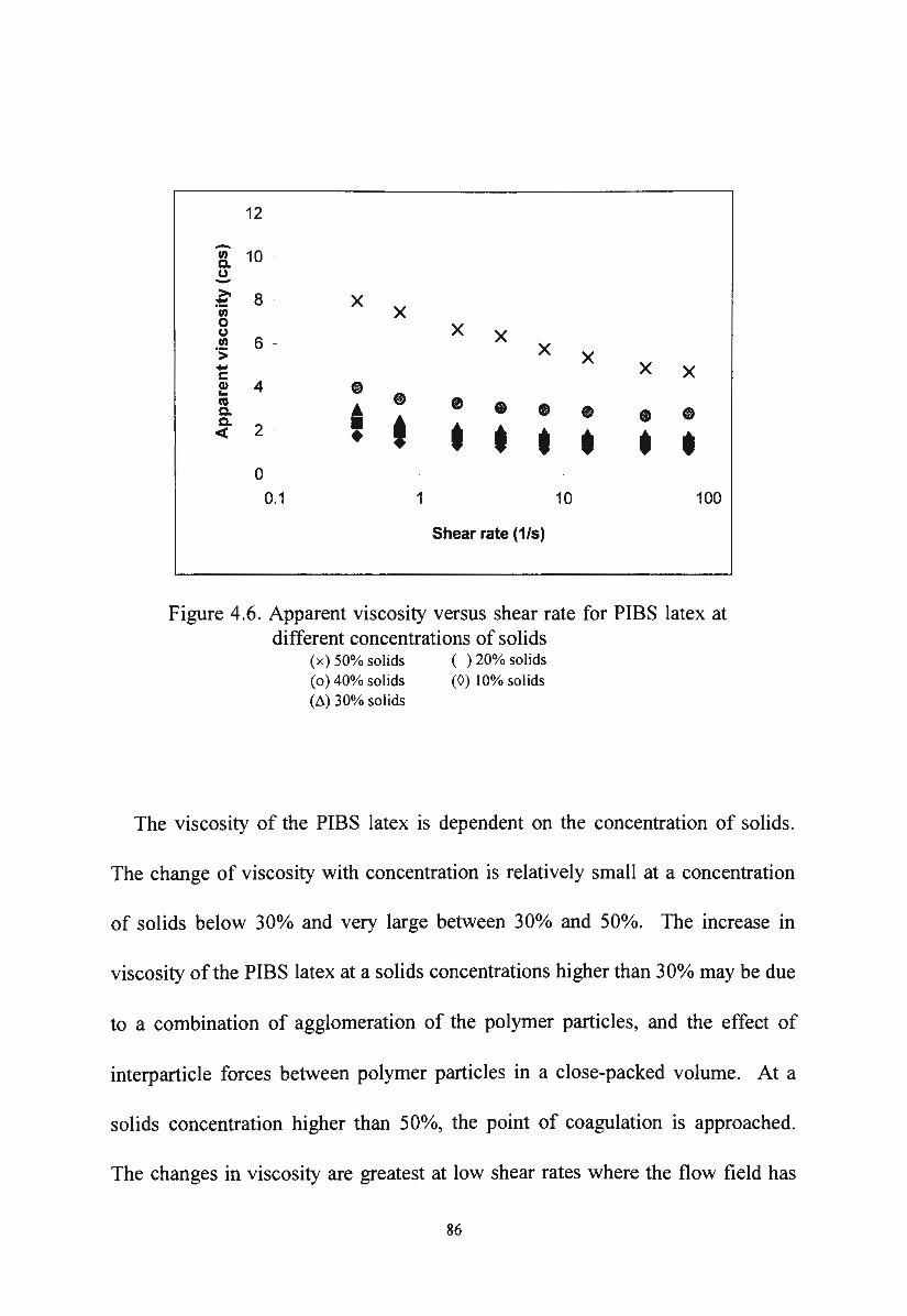
12
-"' 10 Q. u ->. 8 - x ~
"' x 0 x u x "' 6 -·:;: x x - x x c Cl) 4 • ... • ca
A • • • Q. • • • Q. 2 • t t t < • t t t t 0
0.1 1 10 100
Shear rate (1/s)
Figure 4.6. Apparent viscosity versus shear rate for PIBS latex at different concentrations of solids
(x) 50% solids ( o) 40% solids (Li) 30% solids
(. ) 20% solids (0) 10% solids
The viscosity of the PIBS latex is dependent on the concentration of solids.
The change of viscosity with concentration is relatively small at a concentration
of solids below 30% and very large between 30% and 50%. The increase in
viscosity of the PIBS latex at a solids concentrations higher than 30°/o may be due
to a combination of agglomeration of the polymer particles, and the effect of
interparticle forces between polymer particles in a close-packed volume. At a
solids concentration higher than 50o/o, the point of coagulation is approached.
The changes in viscosity are greatest at low shear rates where the flow field has
86
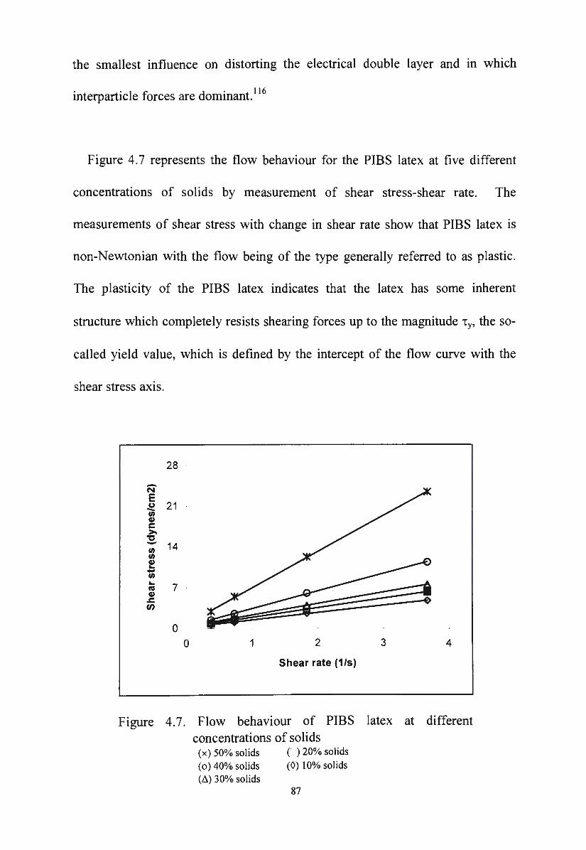
the smallest influence on distorting the electrical double layer and m which
. . 1 .(:" d . 116 mterpart1c e 1orces are ommant.
Figure 4.7 represents the flow behaviour for the PIBS latex at five different
concentrations of solids by measurement of shear stress-shear rate. The
measurements of shear stress with change in shear rate show that PIBS latex is
non-Newtonian with the flow being of the type generally referred to as plastic.
The plasticity of the PIBS latex indicates that the latex has some inherent
structure which completely resists shearing forces up to the magnitude 'ty, the so-
called yield value, which is defined by the intercept of the flow curve with the
shear stress axis.
28
-N E (,) 21 --"' Cl) c >-
't:S - 14 "' "' Cl) ... .. "' ...
7 ns Cl)
.&:.
"' 0
0 1 2 3 4
Shear rate (1/s)
Figure 4.7. Flow behaviour of PIBS latex at different concentrations of solids
(x) 50% solids ( o) 40% solids (~) 30% solids
() 20% solids (0) 10% solids
87
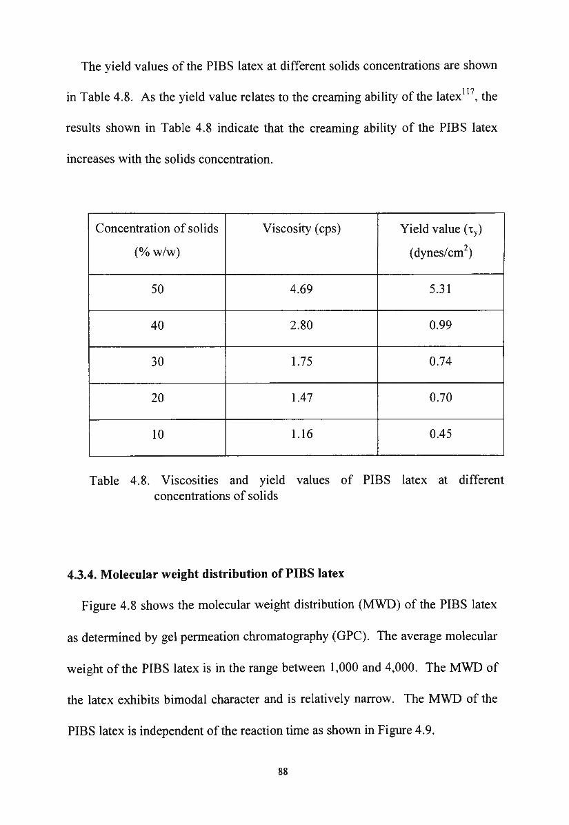
The yield values of the PIBS latex at different solids concentrations are shown
in Table 4.8. As the yield value relates to the creaming ability of the latex 11 7, the
results shown in Table 4.8 indicate that the creaming ability of the PIBS latex
increases with the solids concentration.
Concentration of solids Viscosity (cps) Yield value (1y)
(o/o w/w) (dynes/cm2)
50 4.69 5.31
40 2.80 0.99
30 1.75 0.74
20 1.47 0.70
10 1.16 0.45
Table 4.8. Viscosities and yield values of PIBS latex at different concentrations of solids
4.3.4. Molecular weight distribution of PIBS latex
Figure 4.8 shows the molecular weight distribution (MWD) of the PIBS latex
as determined by gel permeation chromatography (GPC). The average molecular
weight of the PIBS latex is in the range between 1,000 and 4,000. The MWD of
the latex exhibits bimodal character and is relatively narrow. The MWD of the
PIBS latex is independent of the reaction time as shown in Figure 4.9.
88
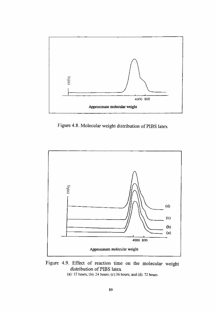
4000 800
Approximate molecular weight
Figure 4.8. Molecular weight distribution of PIBS latex
..:::: . 0 <)
4000 800
Approximate molecular weight
(d)
(b)
(a)
Figure 4.9. Effect of reaction time on the molecular weight distribution of PIBS latex
(a): 12 hours; (b): 24 hours; (c):36 hours; and (d): 72 hours
89
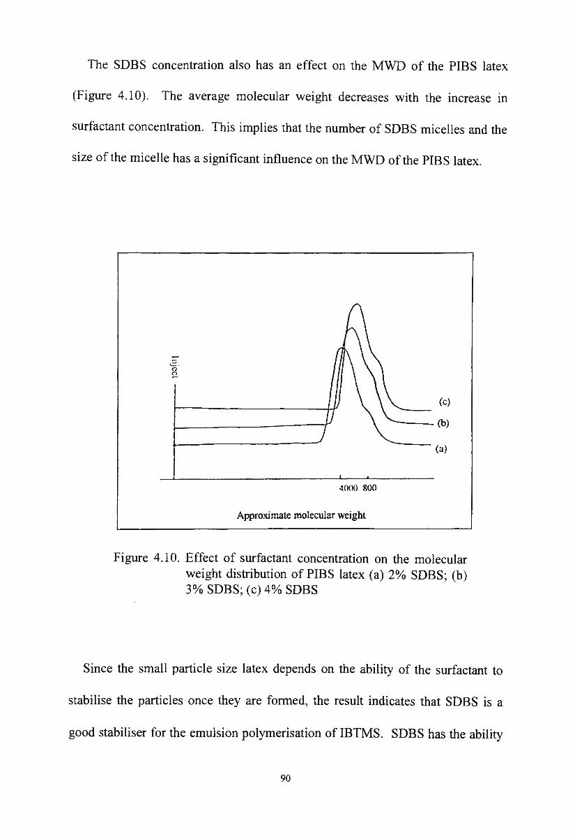
The SDBS concentration also has an effect on the MWD of the PIBS latex
(Figure 4.10). The average molecular weight decreases with the increase in
surfactant concentration. This implies that the number of SDBS micelles and the
size of the micelle has a significant influence on the MWD of the PIBS latex.
-'- · (")
~
4000 800
Approximate molecular weight
(c)
._ __ (b)
(a)
Figure 4.10. Effect of surfactant concentration on the molecular weight distribution of PIBS latex (a) 2% SDBS; (b) 3% SDBS; (c) 4o/o SDBS
Since the small particle size latex depends on the ability of the surfactant to
stabilise the particles once they are formed, the result indicates that SDBS is a
good stabiliser for the emulsion polymerisation of IBTMS. SDBS has the ability
90
to form small PIBS particles and prevents them agglomerating into large particles
(physical effect).
4.3.5. Particle size distribution of PIBS latex
The particle size distribution (PSD) of the PIBS latex is shown in Figure 4.11.
The PSD curve shows that the PIBS latex is a polydispersed system containing
different particles ranging from small particles of 0.1 micron to some large
particles of more than 1 micron. The PSD of the PIBS latex does not change
during storage.
The distribution of particle size becomes narrower and the average particle
size decreases with an increase in the surfactant concentration (Figure 4.12).
This implies that the concentration of the surfactant has an effect on the
monodispersity of the system. As the concentration of the surfactant increases,
the number of SDBS micelles and thus the number of reaction sites increases.
Consequently, the size of the latex particles decreases as the number of reaction
sites increases. The change in the number of latex particles with surfactant
concentration is shown in Table 4.9. The number of latex particles per unit
volume (specific surface area) mcreases as the concentration of the SDBS
increases.
91
I
.I 1 Ill f .ui iclc 1 ia C-1.
(a) freshly prepared latex
I ll
. l l • f.uiick 1ia C-l.
(b) one year old latex
Figure 4.11. Particle size distribution of the PIBS latex
The result also indicates that the SDBS micelles are reaction sites for the
emulsion polymerisation of IBTMS as the particle sizes of the polymer particles
depends on the number of SDBS micelles.
92
:r UI
. 1 1 II f ui.icl• d:a: <-J.
(a) 2% SOBS
UI
• 1 1 • P..ticl< ai::a: 1-1.
(b) 3% SOBS
UI
• 1 l • hrtlck d:a: <-J.
(c) 4% SDBS
Figure 4.12. Effect of the concentration of surfactant on the particle size distribution of the PIBS latex
93
Surfactant concentration (o/ow/w) Specific surface area (m2/ml)
2 16.0580
3 16.4143
4 21.7448
Table 4.9 . Effect of surfactant concentration on the specific surface area of the PIBS latex
4.4. The stability of PIBS latex
The PIBS latex is a colloidal solution and its stability is governed by the same
principles as colloidal sols in general. There are several factors which may
contribute to the stability of the PIBS latex . These factors are : (a) the particle
size of the PIBS latex exhibits a relatively narrow distribution in the range
between 0.01 to 1.00 microns; (b) the PIBS latex exhibits a yield stress at a low
level of shear; ( c) the zeta potential of the latex is relatively high at more than
-50 mV.
According to Shaw, 118 larger particles are less stable than smaller particles on
account of their smaller area-to-volume ratio, and so will tend to grow at the
expense of the small particles. If this process continues, the latex will eventually
94
break. The particle size distribution of the PIBS latex is relatively narrow and
this indicates that the latex has a fairly uniform droplet size, and therefore the
PIBS latex is less prone to this effect.
The PIBS latex exhibits a strong yield stress and a shear thinning behaviour.
This implies that the latex is stabilised by strong electrostatic forces of
repulsion. 119 The strong electrostatic forces of repulsion between the particles in
the PIBS latex is also shown by the relatively high zeta potential of the latex.
The absolute value of the zeta potential of the PIBS latex is about 60 m V and this
is higher than the minimum value of 30 mV required for a stable emulsion. 120
The electrostatic repulsion arising from the charged double layer around the latex
particle effectively decreases the van der Waals attractive forces between the
latex particles. Hence, this prevents the close approach of the particles and
prevents subsequent coalescence.
Another factor which may contribute to the stability of the PIBS latex is the
presence of the hydroxyl end groups of the PIBS at the water-oil interface. In
latex particles, the polymer is a cross-linked polysiloxane with hydroxyl end
groups. The presence of the hydroxyl groups at the oil-water interface leads to
the perturbation of the interfacial energy (~ 4.3 .1 ). As a result, the PIBS has a
peculiar surfactant behaviour. The closed-packed interfacial film composed of
surfactants and hydroxyl groups at the oil-water interface would possess greater
95
strength and resistance to rupture . Hence, the particles would be less liable to
coalesce and the latex achieves significant stability. This physical barrier around
the particles also increase the height of the energy barrier V max (see Chapter 2)
and thus contributes to the stability of the latex. In conclusion, the stability of the
PIBS latex may be attributed to the strong electrostatic repulsion of the adsorbed
ionic emulsifier which is supplemented by the presence of the hydroxyl groups of
the polyisobutylsiloxane.
At low concentration of solids, the latex particles are not close together and the
attraction is overcome by the repulsion between particles and the interparticle
forces are strong enough to prevent coalescence. As the concentration of solids
increases, the distance between particles becomes smaller, the attraction forces
overcome the electrostatic repulsion forces, leading to the aggregation or
coagulation of the latex particles and the latex becomes unstable. For this reason,
the PIBS latex should be stored as a concentrate which contains less than 50°/o of
solids.
96
CHAPTER FIVE
Characterisation and stability of novel silane/siloxane emulsions
5.1. Characterisation of novel silane/siloxane emulsions
As discussed previously, the required properties of the silane/siloxane
emulsions are deep penetration, alkali stability, physical stability, chemical
stability, good beading effect (no wetting effect due to surfactant) and good
performance in terms of water absorption.
In addition, ideally the emulsion should be preparable at a high concentration
of silane and be dilutable to 20-25°/o. In the diluted state, it is necessary for the
emulsion to exhibit satisfactory viscosity to spread on the substrate surfaces by
normal application.
The stability of an emulsion is governed by its physical properties which
determine its characteristics and usefulness for intended applications. Therefore,
in this Chapter, the various properties such as particle size, particle size
distribution, viscosity, zeta potential and the stability of the alkylalkoxysilane in
the novel emulsions will be discussed. The stability of the novel silane/siloxane
emulsions will be discussed in the last section of this Chapter.
97
5.1.1. Particle size distribution of novel silane/siloxane emulsions
5.1.1.1. Particle size distribution of PIBS latex/silane emulsions
The particle size distribution (PSD) of the PIBS latex/silane emulsions is
broader than the PSD of the PIBS latex itself as shown in Figure 5.1. The result
shows that when silane is added to the PIBS latex, the PSD of the PIBS latex is
shifted to a larger size distribution, resulting from the formation of larger silane
droplets in the emulsion (Figure 5 .1 a and 5 .1 b ). Therefore, the number of
particles per unit volume (specific surface area) of the emulsion is smaller than
that of the latex (Table 5.1).
Table 5.1 shows that the specific surface area (SSA) of the PIBS latex/ OTES
emulsion is lower than that of the PIBS latex/IBTES emulsion. The molecular
size of OTES is larger than the molecular size of IBTES due to the hydrocarbon
chain of the octyl group in OTES being longer than the hydrocarbon chain of the
isobutyl group in IBTES. Therefore, the oil droplets in the OTES emulsion may
be larger than the oil droplets in the IBTES emulsion. As a result, the number of
particles per unit volume of the PIBS latex/OTES emulsion is lower than that of
the PIBS latex/IBTES emulsion.
98
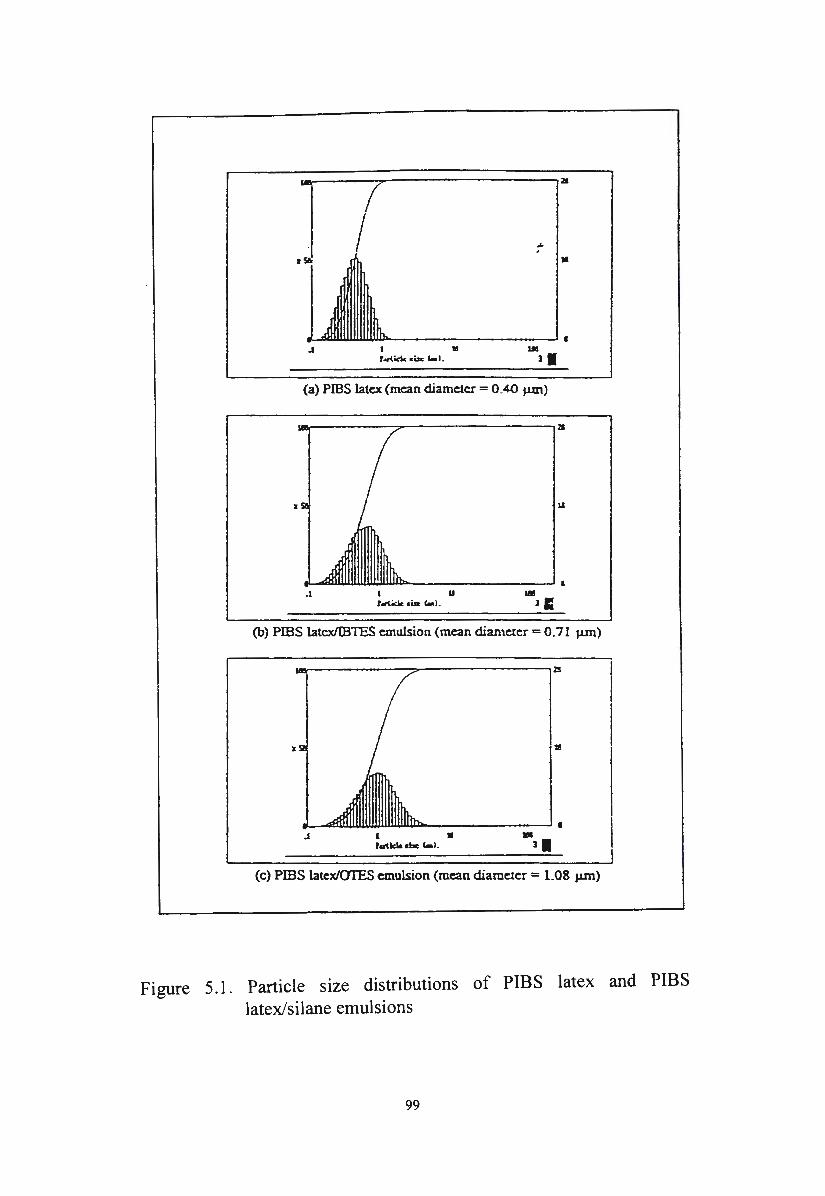
I
.1 I 11! r..ticlc ... 1-l.
(a) PIES latex (mean diameter= 0_4-0 µm)
.1 I 11 Ull r.ri.idc ,._ 1-1 . l I:
(b) PIBS latcx/1B1ES emulsion (mean diameter= 0.71 µm)
z 11!
.1 t • Plrilcl& •bl: 1..1.
(c) PIBS latex/OTES emulsion (mean diameter= LOS µm)
Figure 5.1. Particle size distributions of PIBS latex and PIBS latex/silane emulsions
99
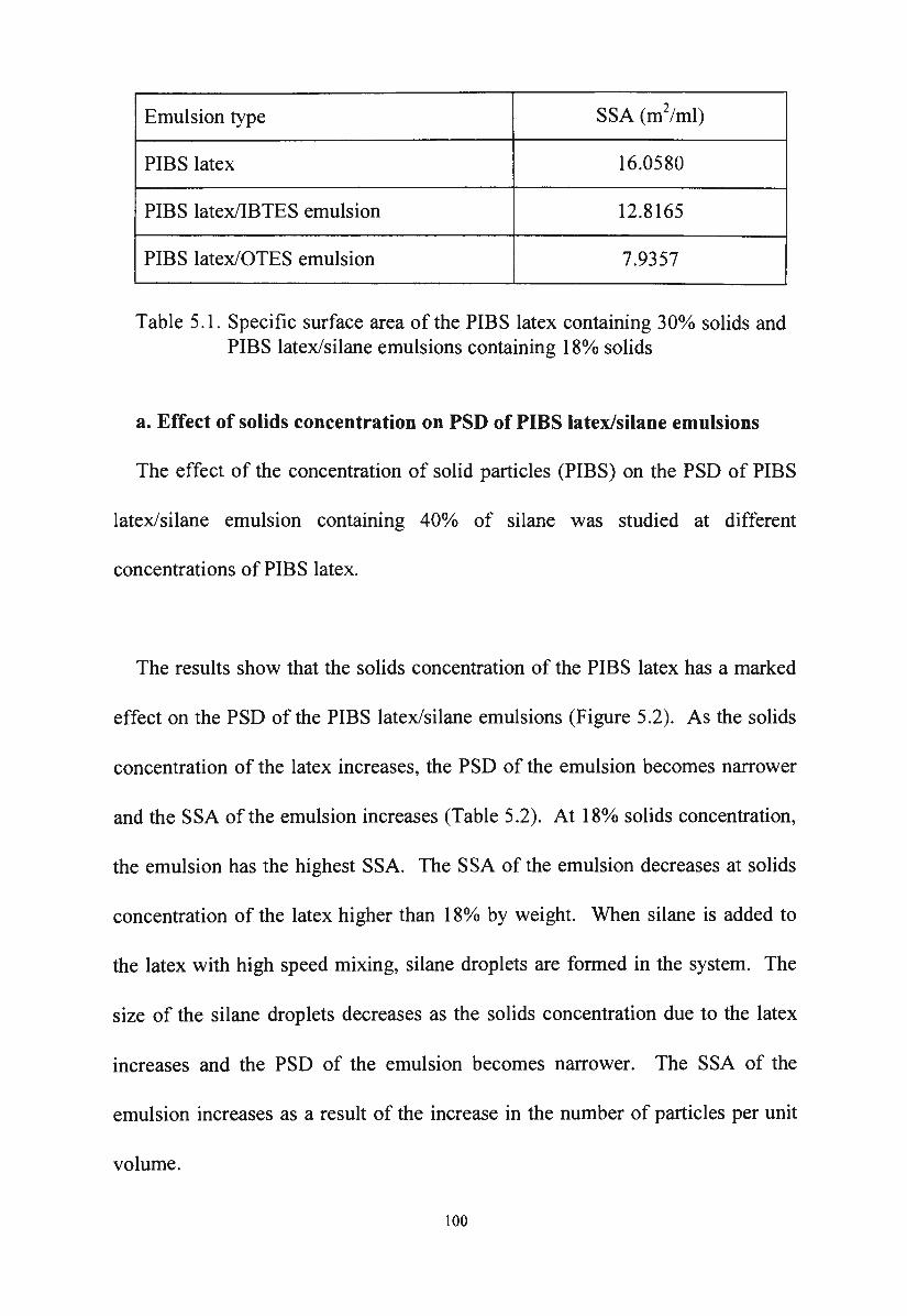
Emulsion type SSA (m2/ml)
PIBS latex 16.0580
PIBS latex/IBTES emulsion 12.8165
PIBS latex/OTES emulsion 7.9357
Table 5.1. Specific surface area of the PIBS latex containing 30% solids and PIBS latex/silane emulsions containing 18% solids
a. Effect of solids concentration on PSD of PIBS latex/silane emulsions
The effect of the concentration of solid particles (PIBS) on the PSD of PIBS
latex/silane emulsion containing 40% of silane was studied at different
concentrations of PIBS latex.
The results show that the solids concentration of the PIBS latex has a marked
effect on the PSD of the PIBS latex/silane emulsions (Figure 5.2). As the solids
concentration of the latex increases, the PSD of the emulsion becomes narrower
and the SSA of the emulsion increases (Table 5.2). At 18% solids concentration,
the emulsion has the highest SSA. The SSA of the emulsion decreases at solids
concentration of the latex higher than l 8o/o by weight. When silane is added to
the latex with high speed mixing, silane droplets are formed in the system. The
size of the silane droplets decreases as the solids concentration due to the latex
increases and the PSD of the emulsion becomes narrower. The SSA of the
emulsion increases as a result of the increase in the number of particles per unit
volume.
100
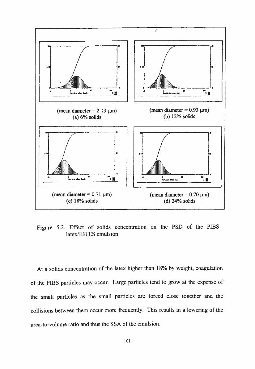
•
.l
(mean diameter = 2. 13 µm) (a) 6% solids
l •
r..ticlc - '-'·
(mean diameter= 0.71 µm) (c) 18% solids
•
•
.l
.l
....
I • fwU<loo .... '-"·
(mean diameter= 0.93 µm) (b) 12% solids
l •
~-'-'-• ,I
(mean diameter= 0.70 µm) (d) 24% solids
•
Figure 5.2. Effect of solids concentration on the PSD of the PIBS latex/IBTES emulsion
At a solids concentration of the latex higher than 18% by weight, coagulation
of the PIBS particles may occur. Large particles tend to grow at the expense of
the small particles as the small particles are forced close together and the
collisions between them occur more frequently . This results in a lowering of the
area-to-volume ratio and thus the SSA of the emulsion.
I 01
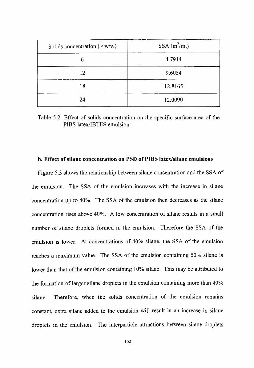
Solids concentration (o/ow/w) SSA (m2/ml)
6 4.7914
12 9.6054
18 12.8165
24 12.0090
Table 5.2. Effect of solids concentration on the specific surface area of the PIBS latex/IBTES emulsion
b. Effect of silane concentration on PSD of PIBS latex/silane emulsions
Figure 5.3 shows the relationship between silane concentration and the SSA of
the emulsion. The SSA of the emulsion increases with the increase in silane
concentration up to 40%. The SSA of the emulsion then decreases as the silane
concentration rises above 40%. A low concentration of silane results in a small
number of silane droplets formed in the emulsion. Therefore the SSA of the
emulsion is lower. At concentrations of 40% silane, the SSA of the emulsion
reaches a maximum value. The SSA of the emulsion containing 50% silane is
lower than that of the emulsion containing 10% silane. This may be attributed to
the formation of larger silane droplets in the emulsion containing more than 40°/o
silane. Therefore, when the solids concentration of the emulsion remains
constant, extra silane added to the emulsion will result in an increase in silane
droplets in the emulsion. The interparticle attractions between silane droplets
102
becomes stronger as the collisions between them become more frequent .
Coalescence of the silane droplets then occurs and larger silane droplets are
formed.
14 -
12 ~
- 10 E - 8 N E
6 < "' 4 -
"' 2 -
0
0 10 20 30 40 50
Silane concentration (o/ow/w)
Figure 5.3. Relationship between SSA and silane concentration
The formation of larger droplets in emulsions containing more than 40% silane
contributes to the instability of the emulsions. In support of this explanation, it
has been found that the shelf life of the PIBS latex/silane emulsions containing
50% silane was less than one week.
c. Effect of shearing on PSD of PIBS latex/silane emulsions
The effect of shearing time by the shear mixer on the SSA is shown in Figure
5.4. The SSA of the emulsion increases with an increase in the shearing time.
103
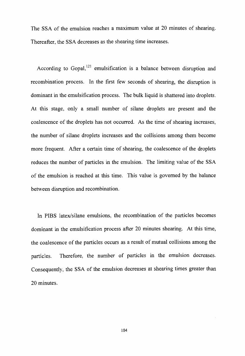
The SSA of the emulsion reaches a maximum value at 20 minutes of shearing.
Thereafter, the SSA decreases as the shearing time increases.
According to Gopal, 121 emulsification is a balance between disruption and
recombination process. In the first few seconds of shearing, the disruption is
dominant in the emulsification process. The bulk liquid is shattered into droplets.
At this stage, only a small number of silane droplets are present and the
coalescence of the droplets has not occurred. As the time of shearing increases,
the number of silane droplets increases and the collisions among them become
more frequent. After a certain time of shearing, the coalescence of the droplets
reduces the number of particles in the emulsion. The limiting value of the SSA
of the emulsion is reached at this time. This value is governed by the balance
between disruption and recombination.
In PIBS latex/silane emulsions, the recombination of the particles becomes
dominant in the emulsification process after 20 minutes shearing. At this time,
the coalescence of the particles occurs as a result of mutual collisions among the
particles. Therefore, the number of particles in the emulsion decreases.
Consequently, the SSA of the emulsion decreases at shearing times greater than
20 minutes.
104
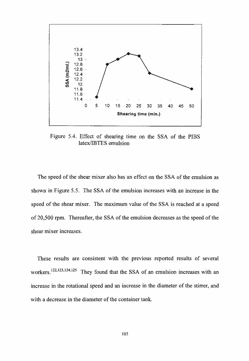
-13.4 13.2
13 -E 12.8 -N 12 .6 E 12.4 -< 12.2 "' 12 "' 11 .8
11 .6 11.4
0 5 10 15 20 25 30 35 40 45 50
Shearing time (min.)
Figure 5.4. Effect of shearing time on the SSA of the PIBS latex/IBTES emulsion
The speed of the shear mixer also has an effect on the SSA of the emulsion as
shown in Figure 5.5. The SSA of the emulsion increases with an increase in the
speed of the shear mixer. The maximum value of the SSA is reached at a speed
of 20,500 rpm. Thereafter, the SSA of the emulsion decreases as the speed of the
shear mixer increases.
These results are consistent with the prev10us reported results of several
workers.122•123
•124
•125 They found that the SSA of an emulsion increases with an
increase in the rotational speed and an increase in the diameter of the stirrer, and
with a decrease in the diameter of the container tank.
105
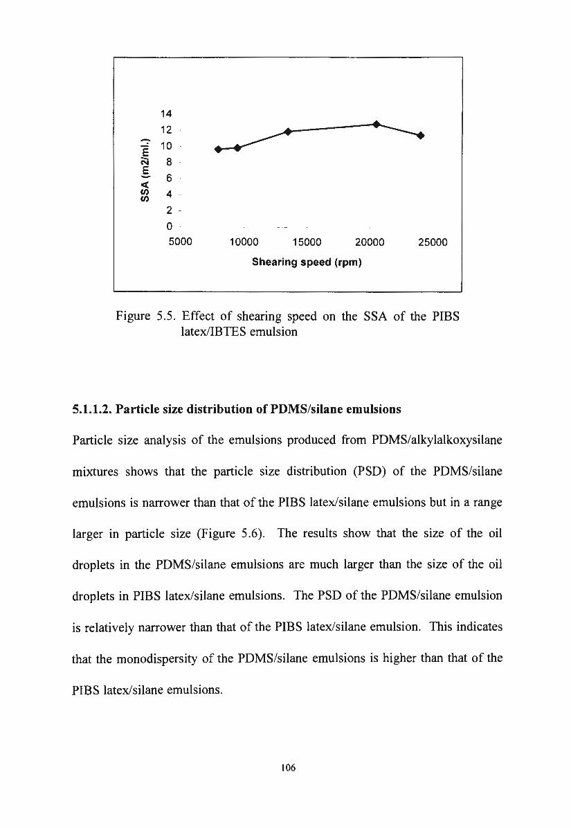
14 -
12
E 10 - 8 N
E 6 -c(
"' 4 -
"' 2 -
0 5000 10000 15000 20000 25000
Shearing speed (rpm)
Figure 5.5. Effect of shearing speed on the SSA of the PIBS latex/IBTES emulsion
5.1.1.2. Particle size distribution of PDMS/silane emulsions
Particle size analysis of the emulsions produced from PDMS/alkylalkoxysilane
mixtures shows that the particle size distribution (PSD) of the PDMS/silane
emulsions is narrower than that of the PIBS latex/silane emulsions but in a range
larger in particle size (Figure 5.6). The results show that the size of the oil
droplets in the PDMS/silane emulsions are much larger than the size of the oil
droplets in PIBS latex/silane emulsions. The PSD of the PDMS/silane emulsion
is relatively narrower than that of the PIBS latex/silane emulsion. This indicates
that the monodispersity of the PDMS/silane emulsions is higher than that of the
PIBS latex/silane emulsions.
106
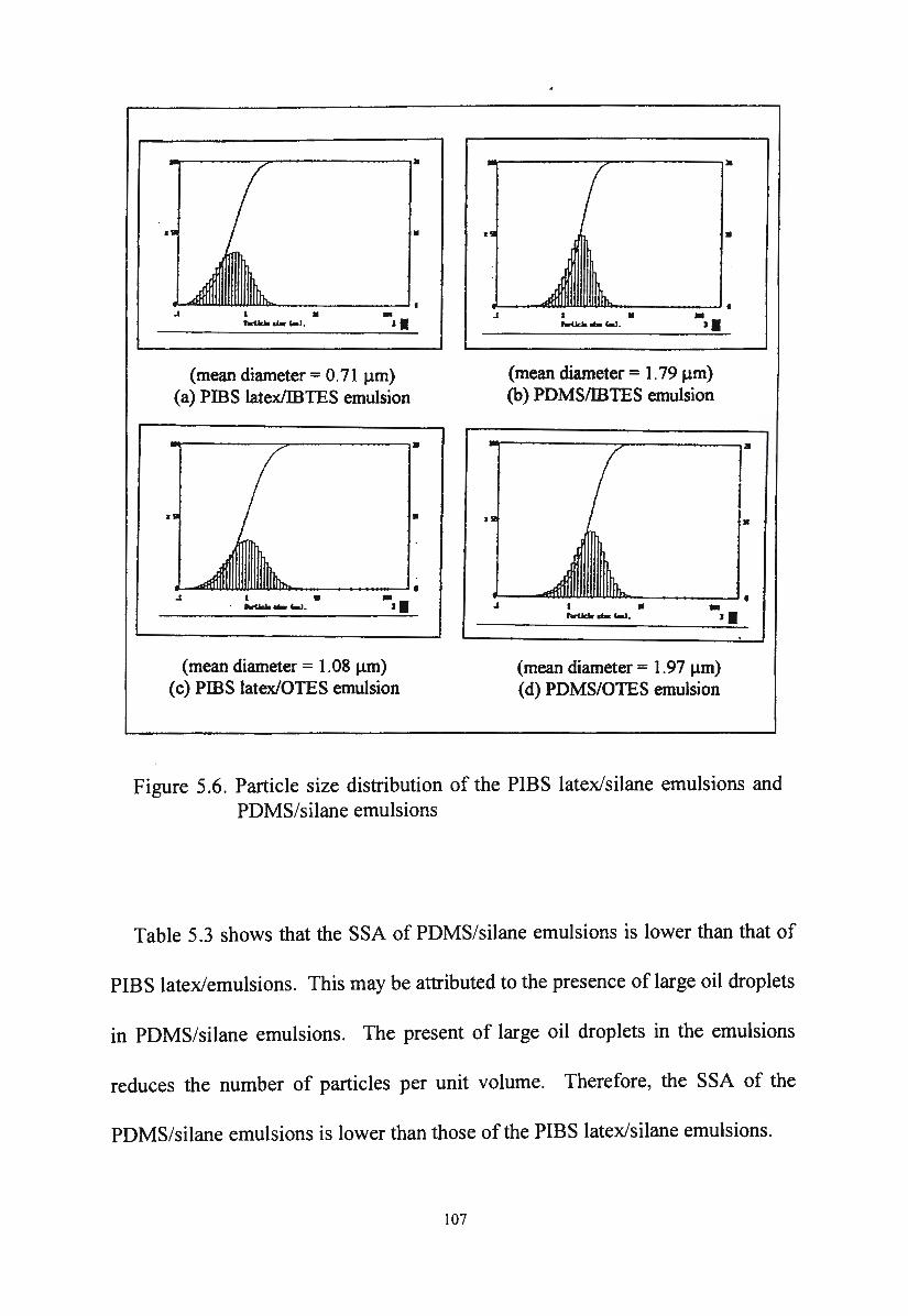
.1 I •
--dar i-1.
(mean diameter = 0. 71 µm) (a) PIBS latex/IBTES emulsion
.1 I • ---'-!. (mean diameter= 1.08 µm)
(c) PIBS latex/OTES emulsion
•
.1 I • hrildo - c..J.
(mean diameter= 1. 79 µm) (b) PDMS/IBTES emulsion
(mean diameter = I. 97 µm) ( d) PD MS/OTES emulsion
•
•
Figure 5.6. Particle size distribution of the PIBS latex/silane emulsions and PDMS/silane emulsions
Table 5.3 shows that the SSA of PDMS/silane emulsions is lower than that of
PIBS latex/emulsions. This may be attributed to the presence of large oil droplets
in PDMS/silane emulsions. The present of large oil droplets in the emulsions
reduces the number of particles per unit volume. Therefore, the SSA of the
PDMS/silane emulsions is lower than those of the PIBS latex/silane emulsions.
107
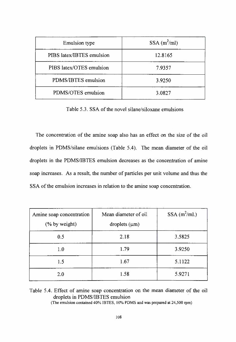
Emulsion type SSA (m2/ml)
PIBS latex/IBTES emulsion 12.8165
PIBS latex/OTES emulsion 7.9357
PDMS/IBTES emulsion 3.9250
PDMS/OTES emulsion 3.0827
Table 5.3. SSA of the novel silane/siloxane emulsions
The concentration of the amine soap also has an effect on the size of the oil
droplets in PDMS/silane emulsions (Table 5.4). The mean diameter of the oil
droplets in the PDMS/IBTES emulsion decreases as the concentration of amine
soap increases. As a result, the number of particles per unit volume and thus the
SSA of the emulsion increases in relation to the amine soap concentration.
Amine soap concentration Mean diameter of oil SSA (m2/ml.)
(%by weight) droplets (µm)
0.5 2.18 3.5825
1.0 1.79 3.9250
1.5 1.67 5.1122
2.0 1.58 5.9271
Table 5.4. Effect of amine soap concentration on the mean diameter of the oil droplets in PDMS/IBTES emulsion
(The emulsion contained 40% IBTES, I 0% PDMS and was prepared at 24,500 rpm)
108
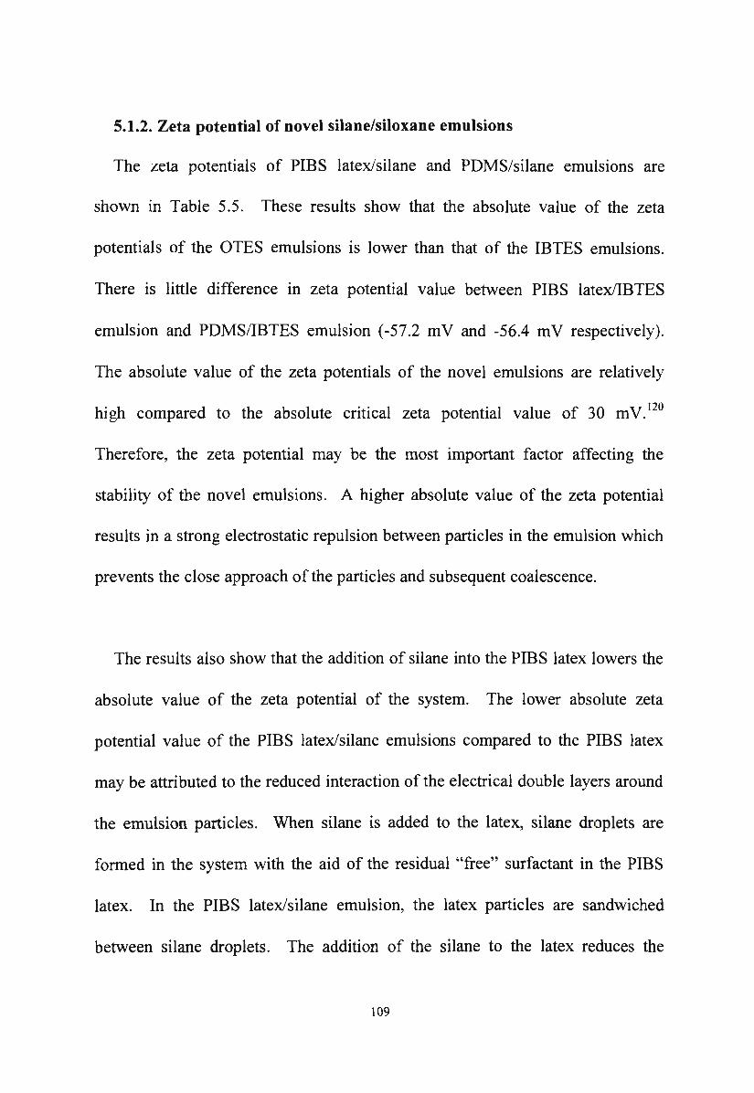
5.1.2. Zeta potential of novel silane/siloxane emulsions
The zeta potentials of PIBS latex/silane and PDMS/silane emulsions are
shown in Table 5.5. These results show that the absolute value of the zeta
potentials of the OTES emulsions is lower than that of the IBTES emulsions.
There is little difference in zeta potential value between PIBS latex/IBTES
emulsion and PDMS/IBTES emulsion (-57.2 mV and -56.4 mV respectively).
The absolute value of the zeta potentials of the novel emulsions are relatively
high compared to the absolute critical zeta potential value of 30 m V. 120
Therefore, the zeta potential may be the most important factor affecting the
stability of the novel emulsions. A higher absolute value of the zeta potential
results in a strong electrostatic repulsion between particles in the emulsion which
prevents the close approach of the particles and subsequent coalescence.
The results also show that the addition of silane into the PIBS latex lowers the
absolute value of the zeta potential of the system. The lower absolute zeta
potential value of the PIBS latex/silane emulsions compared to the PIBS latex
may be attributed to the reduced interaction of the electrical double layers around
the emulsion particles. When silane is added to the latex, silane droplets are
formed in the system with the aid of the residual "free" surfactant in the PIBS
latex. In the PIBS latex/silane emulsion, the latex particles are sandwiched
between silane droplets. The addition of the silane to the latex reduces the
109
number of particles per unit volume and thus the interaction between particles
becomes weaker. The electrostatic repulsion between latex particles in the PIBS
latex/silane emulsion decreases since the presence of the silane droplets makes
the electrical double layer around the latex particles interact less.
Sample Zeta potential ( m V)
PIBS latex/IBTES emulsion -57.2
PIBS latex/OTES emulsion -44.9
PDMS/IBTES emulsion -56.4
PDMS/OTES emulsion -40.5
Table 5.5. Zeta potentials of the novel silane/siloxane emulsions
The significantly lower absolute value of the zeta potential of the OTES
emulsions compared to the IBTES emulsions may be attributed to the large size
of the OTES droplets. The large size of the OTES droplets results in a small
number of particles per unit volume. The distance between particles increases,
the electrical double layers around particles interact less and the electrostatic
repulsion between particles becomes weaker. This results in a lower zeta
potential value of the OTES emulsions compared to the IBTES emulsions.
110
In the PDMS/silane emulsions, the electrostatic repulsion between oil droplets
arises from the adsorption of the anionic surfactant at the oil/water interface,
resulting in the formation of the electrical double layer around the emulsion
droplets . The absolute value of the zeta potentials of the PIBS latex/silane
emulsions are higher than the corresponding PDMS/silane emulsions. This
indicates that the electrostatic repulsions between oil droplets in PDMS/silane
emulsions are weaker than the electrostatic repulsions between particles in the
PIBS latex/silane emulsions.
5.1.3. Viscosity of novel silane/siloxane emulsions
5.1.3.1. Viscosity of PIBS latex/silane emulsions
Viscosity is considered to be an important factor in the application properties
of the emulsion. Emulsions with very low viscosity will cause difficulties in
forming a liquid film on vertical surfaces in the impregnation process.
It is necessary for the silane/siloxane emulsion to have a suitable viscosity
which not only holds the emulsion on the vertical surface but also allows it to
break so that the silane may enter the capillaries of the substrate. There are many
factors which may affect the viscosity of the PIBS latex/silane emulsion. The
study of these factors in this research aimed to optimise the conditions to achieve
a desired viscosity.
111
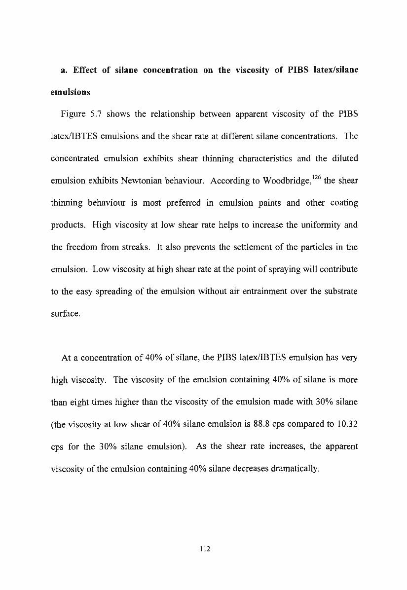
a. Effect of silane concentration on the viscosity of PIBS latex/silane
emulsions
Figure 5.7 shows the relationship between apparent viscosity of the PIBS
latex/IBTES emulsions and the shear rate at different silane concentrations. The
concentrated emulsion exhibits shear thinning characteristics and the diluted
emulsion exhibits Newtonian behaviour. According to Woodbridge, 126 the shear
thinning behaviour is most preferred in emulsion paints and other coating
products. High viscosity at low shear rate helps to increase the uniformity and
the freedom from streaks. It also prevents the settlement of the particles in the
emulsion. Low viscosity at high shear rate at the point of spraying will contribute
to the easy spreading of the emulsion without air entrainment over the substrate
surface.
At a concentration of 40% of silane, the PIBS latex/IBTES emulsion has very
high viscosity. The viscosity of the emulsion containing 40o/o of silane is more
than eight times higher than the viscosity of the emulsion made with 30%> silane
(the viscosity at low shear of 40% silane emulsion is 88.8 cps compared to 10.32
cps for the 30% silane emulsion). As the shear rate increases, the apparent
viscosity of the emulsion containing 40% silane decreases dramatically.
112
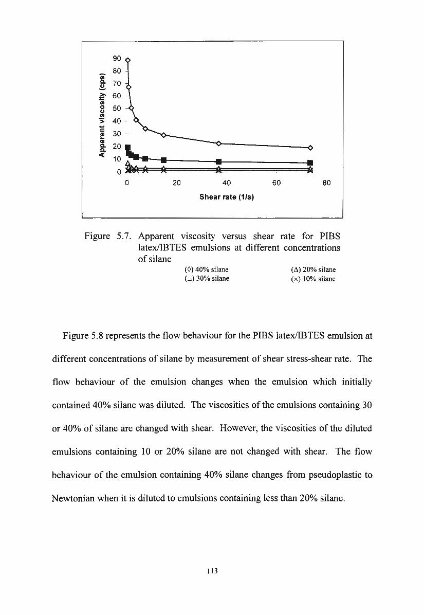
90
80 ' -"' c. 70 ~ ~ 60 -·u; 0 50 ()
"' "> -c Q) ... ca c.
20 '-c. <(
10 -· • • • o~ * ti 0 20 40 60 80
Shear rate (1/s)
Figure 5.7. Apparent viscosity versus shear rate for PIBS latex/IBTES emulsions at different concentrations of silane
(0) 40% silane (:.=) 30% silane
(f1) 20% silane ( x) 1 0% silane
Figure 5.8 represents the flow behaviour for the PIBS latex/IBTES emulsion at
different concentrations of silane by measurement of shear stress-shear rate. The
flow behaviour of the emulsion changes when the emulsion which initially
contained 40o/o silane was diluted. The viscosities of the emulsions containing 30
or 40% of silane are changed with shear. However, the viscosities of the diluted
emulsions containing 10 or 20% silane are not changed with shear. The flow
behaviour of the emulsion containing 40o/o silane changes from pseudoplastic to
Newtonian when it is diluted to emulsions containing less than 20% silane.
113
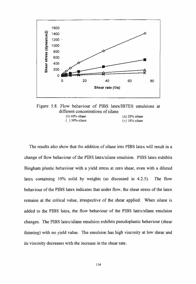
1600 . -N 1400 E (.)
1200 ---rn Cl> c: 1000 ->.
"C - 800 -rn rn Cl> 600 -... -rn ... 400 ca Cl>
200 -.c:
"' 0
0 20 40 60 80
Shear rate (1/s)
Figure 5.8. Flow behaviour of PIBS latex/IBTES emulsions at different concentrations of silane
(0) 40% silane ( ) 30% silane
(M 20% silane (x) 10% silane
The results also show that the addition of silane into PIBS latex will result in a
change of flow behaviour of the PIBS latex/silane emulsion. PIBS latex exhibits
Bingham plastic behaviour with a yield stress at zero shear, even with a diluted
latex containing I 0% solid by weights (as discussed in 4.2.5). The flow
behaviour of the PIBS latex indicates that under flow, the shear stress of the latex
remains at the critical value, irrespective of the shear applied. When silane is
added to the PIBS latex, the flow behaviour of the PIBS latex/silane emulsion
changes. The PIBS latex/silane emulsion exhibits pseudoplastic behaviour (shear
thinning) with no yield value. The emulsion has high viscosity at low shear and
its viscosity decreases with the increase in the shear rate.
114
The flow behaviour of the PIBS latex/OTES emulsion is similar to that of the
PIBS latex/IBTES emulsion as shown in Figure 5.9.
70 .
-V> 60 c. CJ -~ 50 ·u; 0 40 CJ V> ·; .. c: f 20 . ca c. : 10 ....
o~ 0 20
• ;k _
40
Shear rate (1/s)
60 80
Figure 5.9. Apparent viscosity versus shear rate for PIBS latex/OTES emulsions at different concentrations of silane
(0) 40% silane ( ) 30% silane
CM 20% silane (x) 10% silane
Concentrated PIBS latex/OTES emulsion containing 40% silane exhibits
pseudoplastic behaviour. Diluted OTES emulsion containing I Oo/o silane exhibits
Newtonian behaviour as shown in Figure 5.10.
At the same concentration of silane, the viscosity of the PIBS latex/IBTES
emulsion is higher than the viscosity of the PIBS latex/OTES emulsion as shown
in Figure 5.11.
115
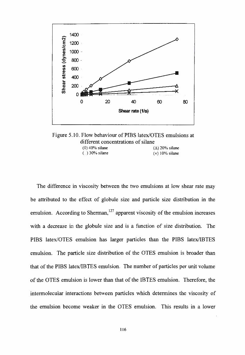
-N E CJ -"' Cl> c: >.
"C -"' "' Cl> ... -"' ... cu Cl> .c:
"'
1400
1200 -
1(XX) -
800 -
6()J .
400 -
200 -
0
0 20 40
Shear rate (1/s)
60 80
Figure 5.10. Flow behaviour of PIBS latex/OTES emulsions at different concentrations of silane
(0) 40% silane ( ) 30% silane
(~) 20% silane (x) 10%silane
The difference in viscosity between the two emulsions at low shear rate may
be attributed to the effect of globule size and particle size distribution in the
emulsion. According to Sherman, 127 apparent viscosity of the emulsion increases
with a decrease in the globule size and is a function of size distribution. The
PIBS latex/OTES emulsion has larger particles than the PIBS latex/IBTES
emulsion. The particle size distribution of the OTES emulsion is broader than
that of the PIBS latex/IBTES emulsion. The number of particles per unit volume
of the OTES emulsion is lower than that of the IBTES emulsion. Therefore, the
intermolecular interactions between particles which determines the viscosity of
the emulsion become weaker in the OTES emulsion. This results in a lower
116
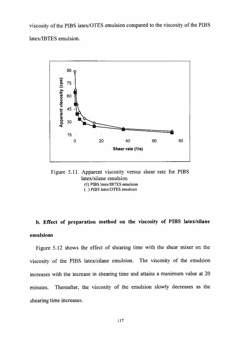
viscosity of the PIBS latex/OTES emulsion compared to the viscosity of the PIBS
latex/IBTES emulsion.
90
-"' c. 75 (.) -~ ·c;; 60 0 (.)
.!? > -c ! "' c. 30 c. <(
15 -
0 20 40 60 80
Shear rate (1/s)
Figure 5.11 . Apparent viscosity versus shear rate for PIBS latex/silane emulsion
(0) PIBS latex/IBTES emulsion C :) PIBS latex/OTES emulsion
b. Effect of preparation method on the viscosity of PIBS latex/silane
emulsions
Figure 5 .12 shows the effect of shearing time with the shear mixer on the
viscosity of the PIBS latex/silane emulsion. The viscosity of the emulsion
increases with the increase in shearing time and attains a maximum value at 20
minutes. Thereafter, the viscosity of the emulsion slowly decreases as the
shearing time increases.
117
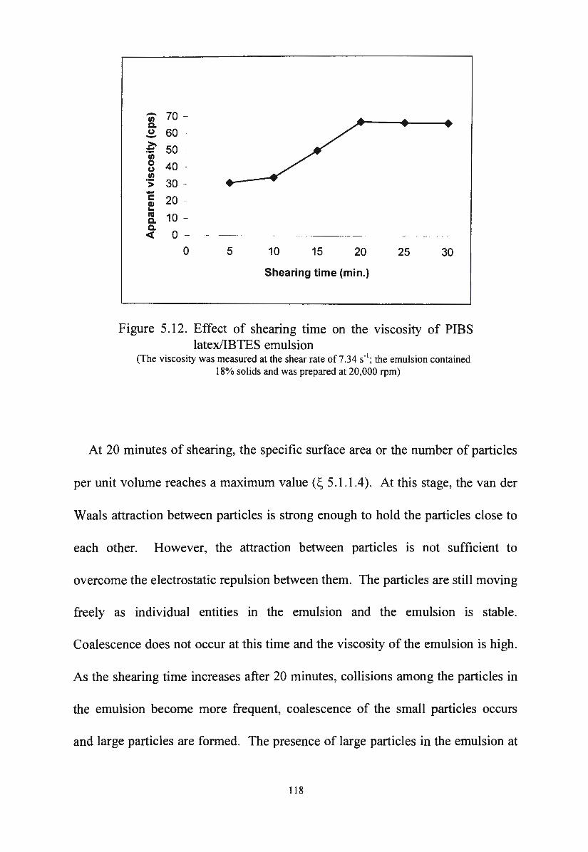
- 70 -"' c. (.) 60 -->. 50 ~
"' 0 40 (.)
.!!? 30 -> -c: 20 C1) ~
"' 10 -c. c. < 0 - -- -~ - -·--··-- --
0 5 10 15 20 25 30
Shearing time (min.)
Figure 5.12. Effect of shearing time on the viscosity of PIBS latex/IBTES emulsion
(The viscosity was measured at the shear rate of 7.34 s· 1; the emulsion contained
18% solids and was prepared at 20,000 rpm)
At 20 minutes of shearing, the specific surface area or the number of particles
per unit volume reaches a maximum value(~ 5.1.1.4). At this stage, the van der
Waals attraction between particles is strong enough to hold the particles close to
each other. However, the attraction between particles is not sufficient to
overcome the electrostatic repulsion between them. The particles are still moving
freely as individual entities in the emulsion and the emulsion is stable.
Coalescence does not occur at this time and the viscosity of the emulsion is high.
As the shearing time increases after 20 minutes, collisions among the particles in
the emulsion become more frequent, coalescence of the small particles occurs
and large particles are formed. The presence of large particles in the emulsion at
118
this stage reduces the number of particles in the emulsion. The interaction
between particles in a unit volume becomes weaker and thus the viscosity of the
emulsion decreases.
The method used to add silane into the latex has an effect on the viscosity of
the emulsion. An emulsion which is prepared by injecting 2 grams of silane each
time into the latex during the shearing process is more viscous than an emulsion
which is prepared by adding silane drop by drop into the latex. The viscosity of
the emulsion which is prepared by adding silane in very small increments into the
latex is lower than the viscosity of the emulsion prepared by introducing silane in
bulk to the latex before shearing as shown in Figure 5.13.
c. Effect of solids concentration on the viscosity of PIBS latex/silane
emulsions
Figure 5.14 shows that the viscosity of the PIBS latex/silane emulsion depends
on the concentration of solid in the emulsion. The viscosity of the emulsion
increases with an increase in the solids concentration.
The solids concentration of the emulsion has an effect on the particle size and
the PDMS of the PIBS latex/silane emulsions (as discussed in 5.1.1. l.a).
Therefore, the viscosity of the PIBS latex/silane emulsion depends on the solids
concentration of the emulsion.
119
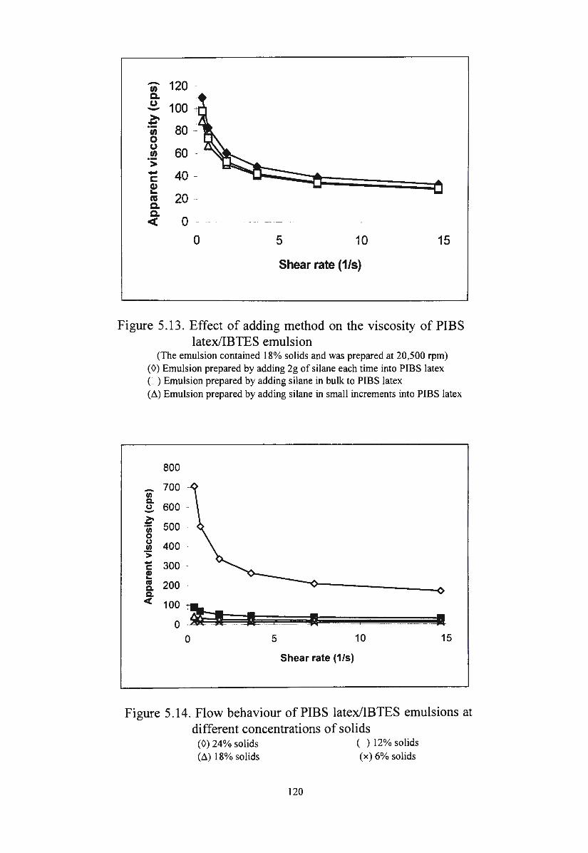
- 120 "' Q. C,) 100 -~ 80 ~ "' 0 C,)
60 -"' ·:;: - 40 -c Cl,) ....
20 -ca Q. Q.
0 -ct -
0 5 10 15
Shear rate (1/s)
Figure 5 .13 . Effect of adding method on the viscosity of PIBS latex/IBTES emulsion
(The emulsion contained 18% solids and was prepared at 20,500 rpm) (0) Emulsion prepared by adding 2g of silane each time into PIBS latex (: ) Emulsion prepared by adding silane in bulk to PIBS latex (~)Emulsion prepared by adding silane in small increments into PIBS latex
800
700 Ci) Q, ~ 600 ~ «;; 500 0
~ 400 ·s: -c e ftS Q, Q,
c( 100 7!--0 ~-;( iL =
0 5 • I 10 15
Shear rate (1/s)
Figure 5.14. Flow behaviour of PIBS latex/IBTES emulsions at different concentrations of solids
(0) 24% solids (M 18%solids
120
( ) 12% solids
(x) 6% solids
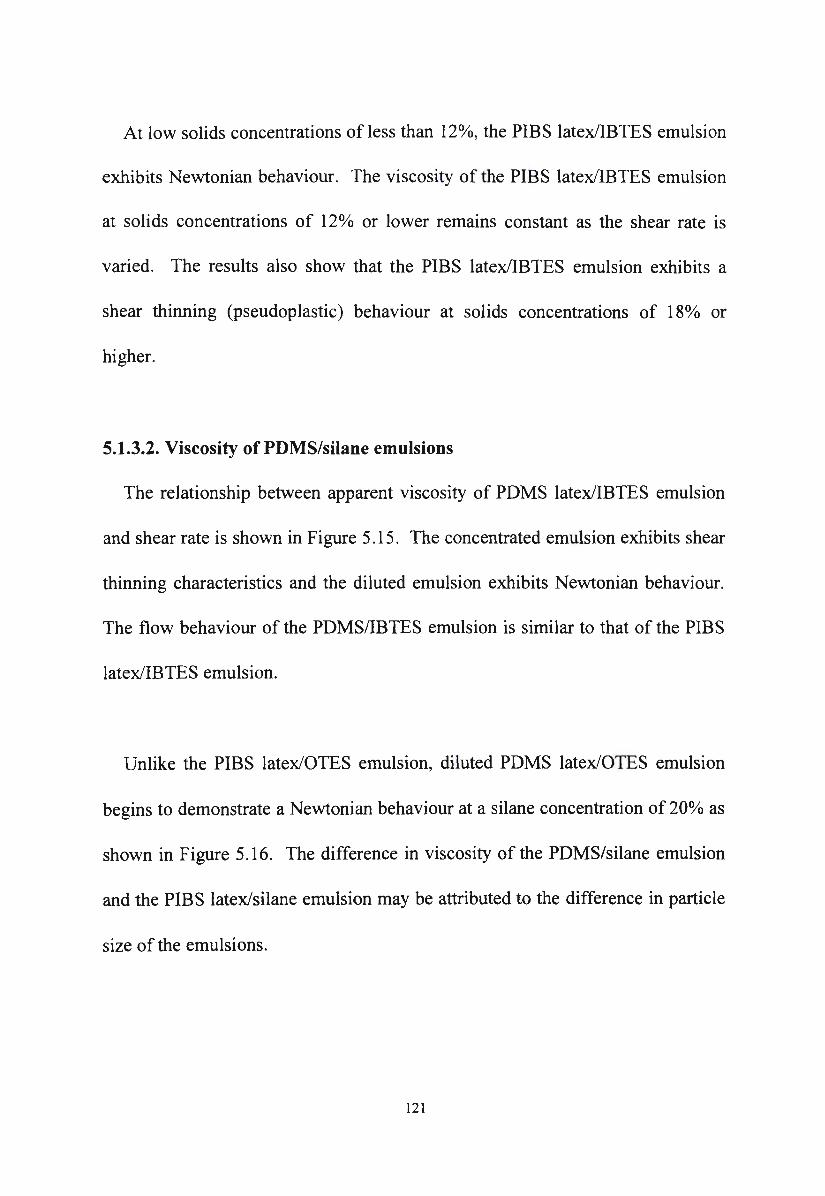
At low solids concentrations of less than 12%, the PIBS latex/IBTES emulsion
exhibits Newtonian behaviour. The viscosity of the PIBS latex/IBTES emulsion
at solids concentrations of 12o/o or lower remains constant as the shear rate is
varied. The results also show that the PIBS latex/IBTES emulsion exhibits a
shear thinning (pseudoplastic) behaviour at solids concentrations of 18% or
higher.
5.1.3.2. Viscosity of PDMS/silane emulsions
The relationship between apparent viscosity of PDMS latex/IBTES emulsion
and shear rate is shown in Figure 5 .15. The concentrated emulsion exhibits shear
thinning characteristics and the diluted emulsion exhibits Newtonian behaviour.
The flow behaviour of the PDMS/IBTES emulsion is similar to that of the PIBS
latex/IBTES emulsion.
Unlike the PIBS latex/OTES emulsion, diluted PDMS latex/OTES emulsion
begins to demonstrate a Newtonian behaviour at a silane concentration of 20% as
shown in Figure 5.16. The difference in viscosity of the PDMS/silane emulsion
and the PIBS latex/silane emulsion may be attributed to the difference in particle
size of the emulsions.
121
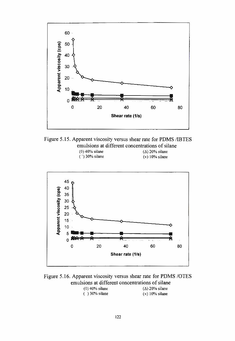
-tn c. (.) -
60 -
~ 40 tn 0 (.)
.!!? > -c: ~ ftl c. ~ 10 '
0 =:--t -0 20
.. I _ 40
Shear rate (1/s)
60
--- __ I 80
Figure 5 .15. Apparent viscosity versus shear rate for PDMS /IBTES emulsions at different concentrations of silane
-tn c. (.) -~ tn 0 (.) In ·:;;: -c: cu ... ftl c. c. c(
45 40
35 30 25 20 15 -·
10
5 5
(0) 40% silane C ) 30% silane
• • o~ ~
0 20
• 40
Shear rate (1/s)
(Li) 20% silane (x) 10% silane
60
• 80
Figure 5.16. Apparent viscosity versus shear rate for PDMS /OTES emulsions at different concentrations of silane
(0) 40% silane ( ) 30% silane
122
(Li) 20% silane (x) 10% silane
The particles in the PIBS latex/silane emulsions are smaller than the particles
in the PDMS/silane emulsions. The number of particles in a unit volume of PIBS
latex/silane emulsion is higher than that of PDMS/silane emulsion. The
interaction between particles in PIBS latex/silane emulsions is stronger than the
interaction between particles in PDMS/silane emulsions. Therefore, the viscosity
of the PIBS latex/silane emulsion is higher than the viscosity of the PDMS/silane
emulsion (Figure 5 .17).
Figure 5.17 also shows that the silane structure has an effect on the viscosity of
the PDMS/silane emulsions. The viscosity of PDMS/IBTES emulsion is higher
than the viscosity of the PDMS/OTES emulsion. The size of the oil droplets in
the PDMS/IBTES emulsion is smaller than the size of the oil droplets in the
PD MS/OTES emulsion. Therefore, the viscosity of the PDMS/IBTES emulsion
is higher than the viscosity of the PD MS/OTES emulsion.
The viscosity of the PDMS/silane emulsions depends on the PDMS
concentration as the silane concentration is held constant at 40o/o. The viscosity
of the PDMS/IBTES emulsion which contains 40% silane increases as the
concentration of PDMS increases from 2% to 10%. The viscosity of the
emulsion reaches a maximum value at a PDMS concentration of 10%.
Thereafter, the viscosity of the emulsion decreases as the concentration of PDMS
increases (Figure 5.18).
123
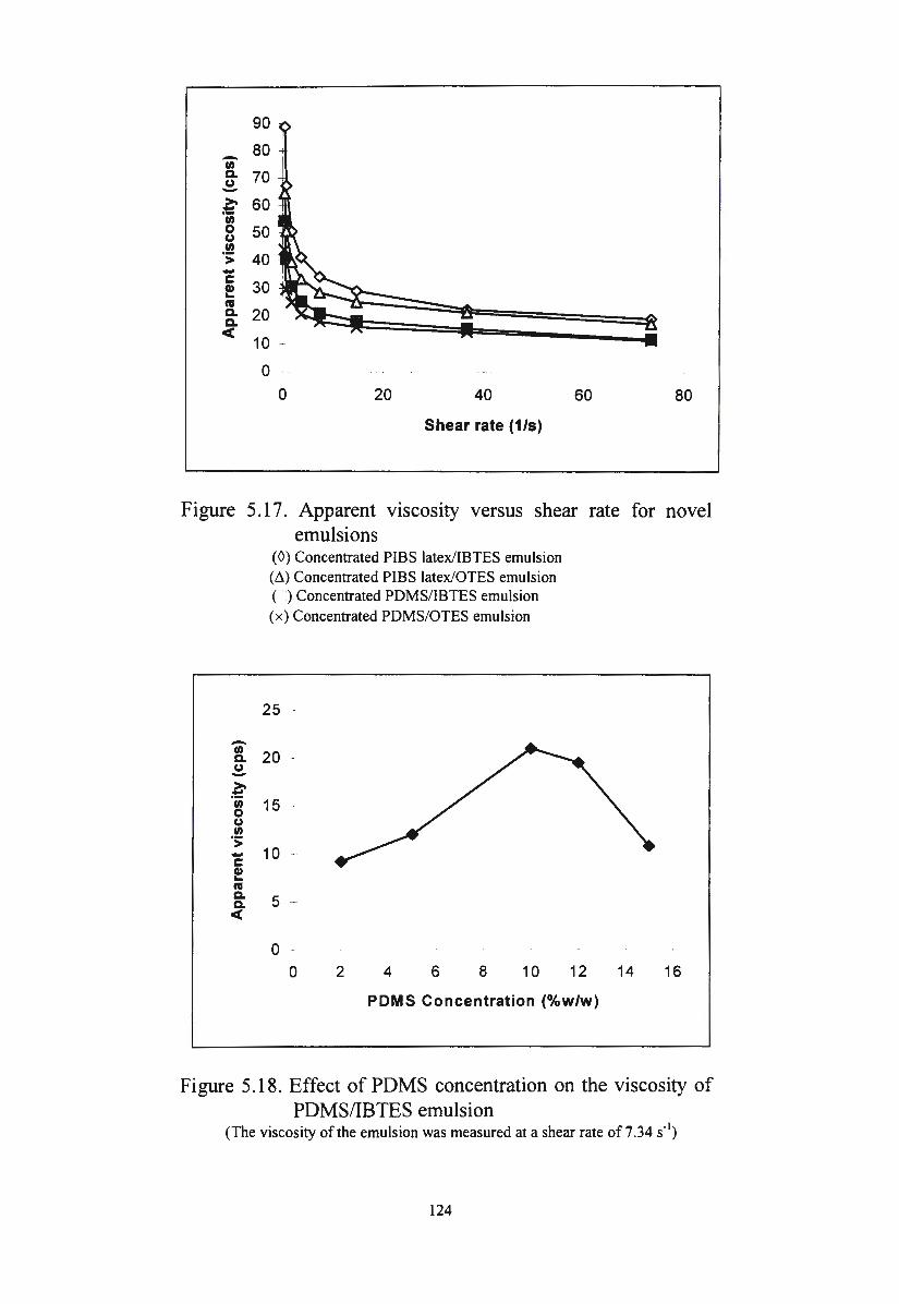
90
80 -fl) Cl. 70 u -~ 60 ·u; 0 50 u fl) ·:;: 40 -c
30 f ftS Cl. Cl. <(
0 --
0 20 40 60 80
Shear rate (1/s)
Figure 5.17. Apparent viscosity versus shear rate for novel
-fl) Cl. CJ -~ (I) 0 u (I)
·:;: -c: f "' Cl. Cl. <(
emulsions (0) Concentrated PIBS latex/IBTES emulsion (M Concentrated PIBS latex/OTES emulsion ( -) Concentrated PDMS/IBTES emulsion (x) Concentrated PDMS/OTES emulsion
25
20 -
15
10 -
5 -
0 0 2 4 6 8 10 12
PDMS Concentration (%w/w)
14 16
Figure 5.18. Effect of PDMS concentration on the viscosity of PDMS/IBTES emulsion
(The viscosity of the emulsion was measured at a shear rate of 7.34 s-1)
124
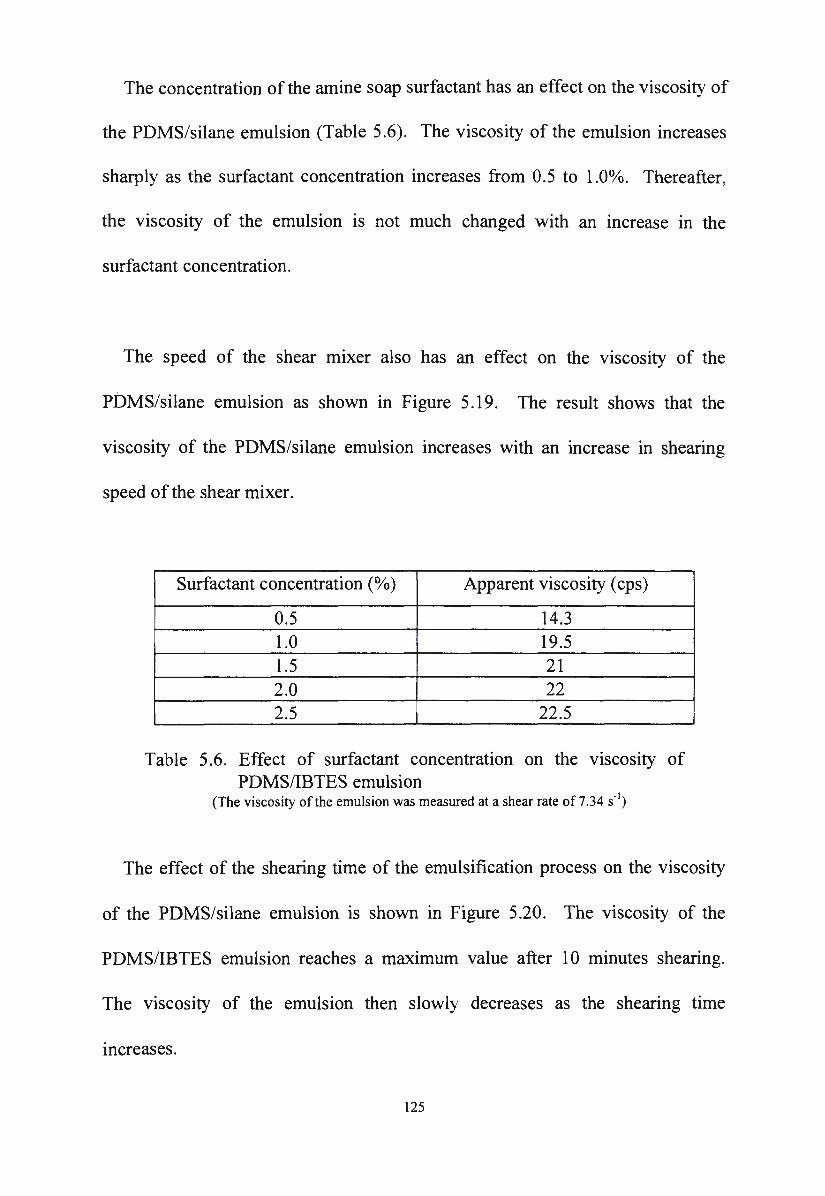
The concentration of the amine soap surfactant has an effect on the viscosity of
the PDMS/silane emulsion (Table 5.6). The viscosity of the emulsion increases
sharply as the surfactant concentration increases from 0.5 to 1.0°/o. Thereafter,
the viscosity of the emulsion is not much changed with an increase in the
surfactant concentration.
The speed of the shear mixer also has an effect on the viscosity of the
PDMS/silane emulsion as shown in Figure 5.19. The result shows that the
viscosity of the PDMS/silane emulsion increases with an increase in shearing
speed of the shear mixer.
Surfactant concentration (o/o) Apparent viscosity (cps)
0.5 14.3 1.0 19.5 1.5 21 2.0 22 2.5 22 .5
Table 5.6. Effect of surfactant concentration on the viscosity of PDMS/IBTES emulsion
(The viscosity of the emulsion was measured at a shear rate of 7.34 s" 1)
The effect of the shearing time of the emulsification process on the viscosity
of the PDMS/silane emulsion is shown in Figure 5.20. The viscosity of the
PDMS/IBTES emulsion reaches a maximum value after 10 minutes shearing.
The viscosity of the emulsion then slowly decreases as the shearing time
increases.
125
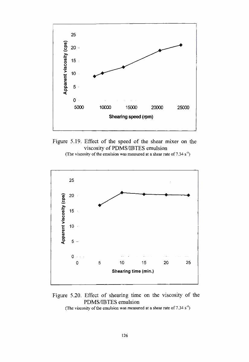
25
-"' c.. 20 --(.J ->. :!:
"' 15 .. 0 (.J
"' ·:;: 10 -....
c: Cl) ... cu
5 -c.. c.. <
0
5000 10000 15000 20000 25000
Shearing speed (rpm)
Figure 5.19. Effect of the speed of the shear mixer on the viscosity of PDMS/IBTES emulsion
(The viscosity of the emulsion was measured at a shear rate of 7.34 s-1)
25
- 20 / • • • "' c. 0 -~ "' 15 . 0 0 .!!! > - 10 c: G> ... cu c. c. 5 -<(
0 ·-- - --1
0 5 10 15 20 25
Shearing time (min.)
Figure 5.20. Effect of shearing time on the viscosity of the PDMS/IBTES emulsion
(The viscosity of the emulsion was measured at a shear rate of 7.34 s· 1)
126
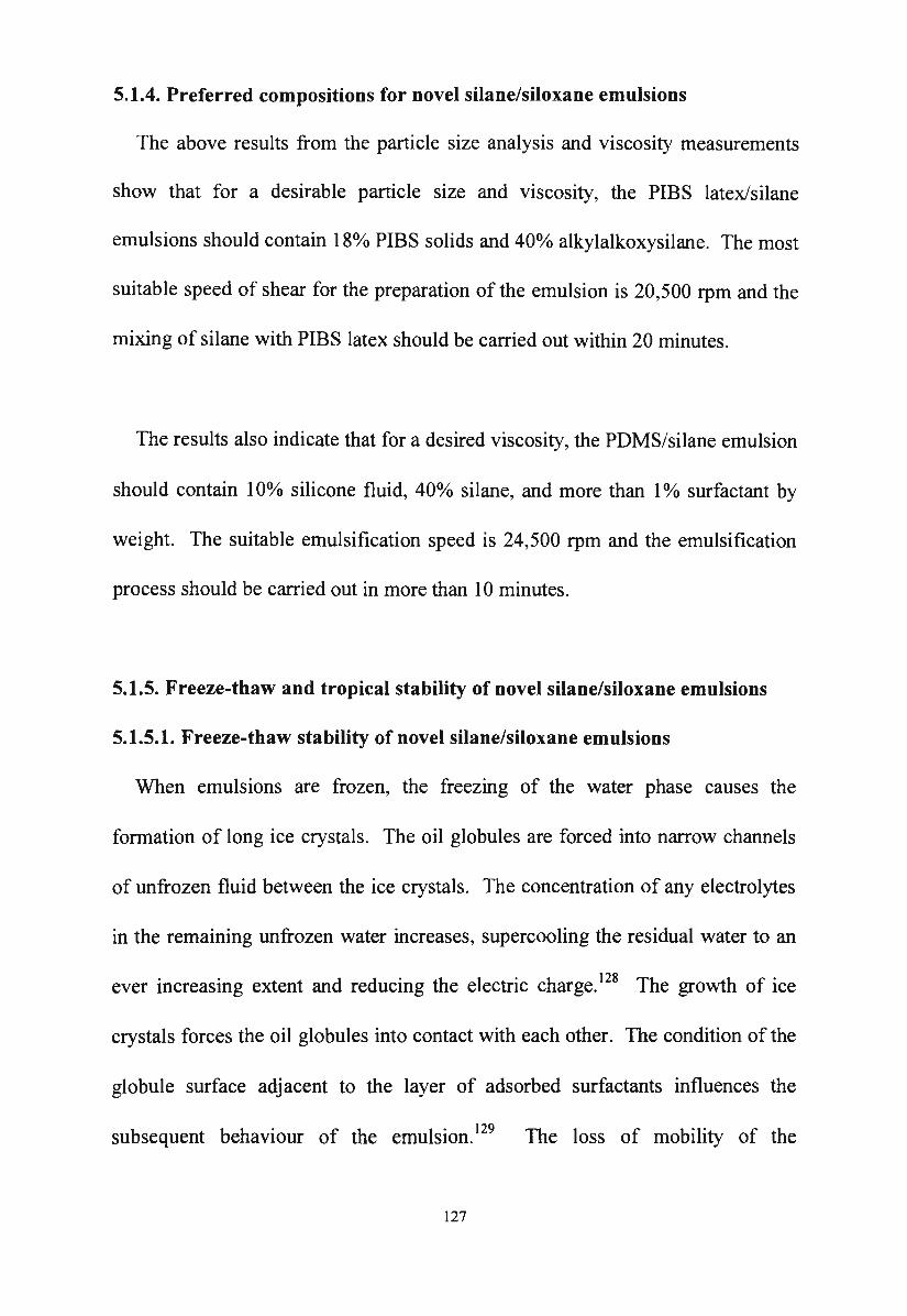
5.1.4. Preferred compositions for novel silane/siloxane emulsions
The above results from the particle size analysis and viscosity measurements
show that for a desirable particle size and viscosity, the PIBS latex/silane
emulsions should contain l 8o/o PIBS solids and 40% alkylalkoxysilane. The most
suitable speed of shear for the preparation of the emulsion is 20,500 rpm and the
mixing of silane with PIBS latex should be carried out within 20 minutes.
The results also indicate that for a desired viscosity, the PDMS/silane emulsion
should contain I 0% silicone fluid, 40% silane, and more than I% surfactant by
weight. The suitable emulsification speed is 24,500 rpm and the emulsification
process should be carried out in more than I 0 minutes.
5.1.5. Freeze-thaw and tropical stability of novel silane/siloxane emulsions
5.1.5.1. Freeze-thaw stability of novel silane/siloxane emulsions
When emulsions are frozen, the freezing of the water phase causes the
formation of long ice crystals. The oil globules are forced into narrow channels
of unfrozen fluid between the ice crystals. The concentration of any electrolytes
in the remaining unfrozen water increases, supercooling the residual water to an
ever increasing extent and reducing the electric charge. 128 The growth of ice
crystals forces the oil globules into contact with each other. The condition of the
globule surface adjacent to the layer of adsorbed surfactants influences the
subsequent behaviour of the emulsion. 129 The loss of mobility of the
127
hydrophobic part of the adsorbed surfactant molecule occurs when the viscosity
of the globule surface reaches that of a solid state. This prevents self
regeneration during the continuous deformation of the oil globules under pressure
exerted by the ice crystals. Consequently, an uneven distribution of surfactants
on the oil globule surface occurs. Coalescence begins at the part of the oil
globule which is not covered by surfactants. Pospelova et al. 130 have shown that
the extent of coalescence is influenced by the nature of the surfactant. Kistler131
has also indicated that the coalescence of the oil globules on cooling depends on
the extent of globule surface covered by surfactant and the nature of the oil
phase. The degree of coalescence increases with the increase in the hydrophobic
chain in the surfactant molecule which is attributed to the inhibition of self
generation as the viscosity in the vicinity of the globule surface is increased. The
extent to which dehydration takes place is controlled by the length of the
hydrophilic chain in the surfactant molecule which may render instability during
freezing. The coalescence during freezing is minimised with an optimum balance
between the hydrophilic and hydrophobic parts of the surfactant molecules. 127
Singleton et al. 132 have pointed out that both freezing and thawing rate have an
influence on the stability. It has been found that rapid freezing and a moderate
rate of thawing lead to greater instability than any other conditions. The nature
and the melting point of the oil phase also affect the degree of coalescence.
128
The freeze-thaw stability tests on the novel emulsions showed that the PIBS
latex/silane emulsions are sensitive to frost. The mechanism of coagulation
during freezing may be attributed to the accumulation of dispersed phase particles
which are rejected by the growing ice crystal lattice. The growing of the ice
crystal lattice ultimately forces the primary PIBS particles into intimate contact
with each other and so promotes coalescence. Barb and Mikucki 133 have worked
on polystyrene emulsions and found that the particles which coagulated tended to
be smaller. The more rapid the freezing and the more concentrated the emulsion,
the larger are the particles formed. This research work was carried out with
polystyrene latex emulsions and the principles may be extended to the PIBS
latex/silane emulsions. In the PIBS latex/silane emulsions, the large number of
small PIBS particles may contribute to the instability of the emulsions to
freezing.
PDMS/silane emulsions were found to be more freeze-thaw stable than PIBS
latex/silane emulsions. This may be due to the steric stabilisation effect134 of
PDMS at the water-oil interface. The high molecular weight PDMS molecule is
flexible and thermally stable. 135 When PDMS/silane emulsions are frozen,
PDMS creates a mobile phase and protects the charge on the emulsion droplets
which causes sufficient repulsion to prevent coalescence. The particle sizes of
the PDMS/silane emulsions are larger than the particle sizes of the PIBS latex
129
emulsions and this may be another factor which contributes to the freeze-thaw
stability of the PDMS/silane emulsions.
5.1.5.2. Tropical stability of novel silane/siloxane emulsions
Tropical stability of emulsions is a factor related to the fundamental
metastability of emulsions. When the temperature increases, the viscosity of the
emulsion changes and the gravitational effects become more pronounced.
Therefore, in silane/siloxane emulsions, the polysiloxane particles which have a
density greater than water may tend to sediment. Certain chemical changes may
also occur in the emulsion and these changes may be accelerated by the heat at
the experimental tropical temperature.
Tests carried out within this research showed that the novel silane/siloxane
emulsions were stable at the experimental tropical temperature of 40°C. The
emulsions were stored at 40°C for more than one month and there was no sign of
separation or the formation of a serum on the surface of the emulsions after they
were cooled down. The stability of the novel silane/siloxane emulsion at higher
temperatures was also shown when the emulsion was heated to 90°C in an oil
bath during headspace chromatography analysis. The emulsion still remained
stable without any sign of the formation of a serum on the surface after being
cooled down.
130
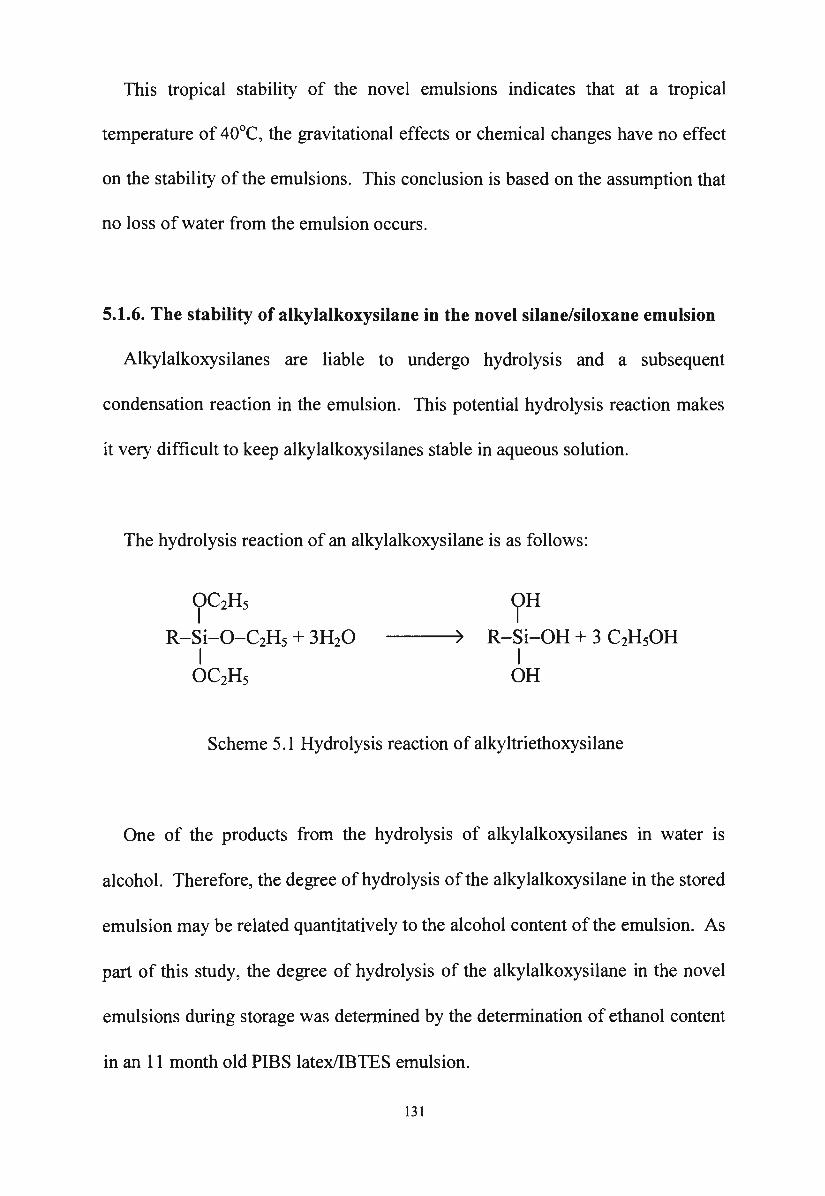
This tropical stability of the novel emulsions indicates that at a tropical
temperature of 40°C, the gravitational effects or chemical changes have no effect
on the stability of the emulsions. This conclusion is based on the assumption that
no loss of water from the emulsion occurs.
5.1.6. The stability of alkylalkoxysilane in the novel silane/siloxane emulsion
Alkylalkoxysilanes are liable to undergo hydrolysis and a subsequent
condensation reaction in the emulsion. This potential hydrolysis reaction makes
it very difficult to keep alkylalkoxysilanes stable in aqueous solution.
The hydrolysis reaction of an alkylalkoxysilane is as follows:
?C2Hs
R-Si-O-C2H5 + 3H20 I
OC2Hs
?H R-Si-OH + 3 C2H50H
I OH
Scheme 5 .1 Hydrolysis reaction of alkyltriethoxysilane
One of the products from the hydrolysis of alkylalkoxysilanes in water is
alcohol. Therefore, the degree of hydrolysis of the alkylalkoxysilane in the stored
emulsion may be related quantitatively to the alcohol content of the emulsion. As
part of this study, the degree of hydrolysis of the alkylalkoxysilane in the novel
emulsions during storage was determined by the determination of ethanol content
in an 11 month old PIBS latex/IBTES emulsion.
131
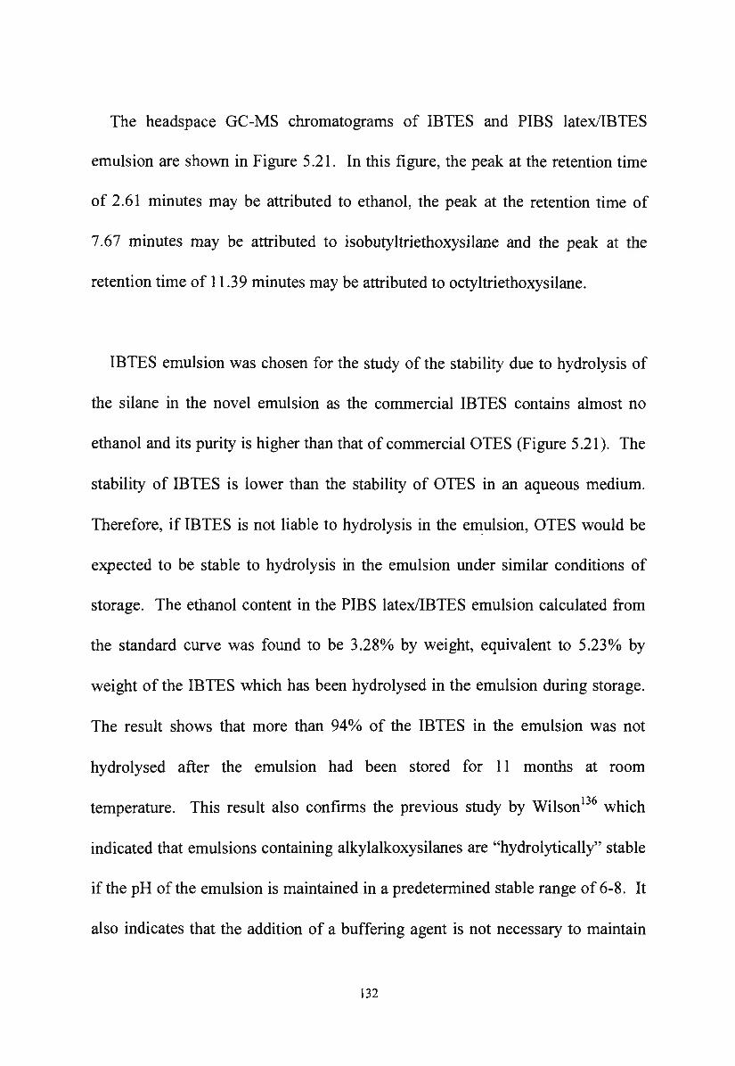
The headspace GC-MS chromatograms of IBTES and PIBS latex/IBTES
emulsion are shown in Figure 5 .21. In this figure, the peak at the retention time
of 2.61 minutes may be attributed to ethanol, the peak at the retention time of
7.67 minutes may be attributed to isobutyltriethoxysilane and the peak at the
retention time of 11 .39 minutes may be attributed to octyltriethoxysilane.
IBTES emulsion was chosen for the study of the stability due to hydrolysis of
the silane in the novel emulsion as the commercial IBTES contains almost no
ethanol and its purity is higher than that of commercial OTES (Figure 5.21). The
stability of IBTES is lower than the stability of OTES in an aqueous medium.
Therefore, if IBTES is not liable to hydrolysis in the emulsion, OTES would be
expected to be stable to hydrolysis in the emulsion under similar conditions of
storage. The ethanol content in the PIBS latex/IBTES emulsion calculated from
the standard curve was found to be 3.28% by weight, equivalent to 5.23% by
weight of the IBTES which has been hydrolysed in the emulsion during storage.
The result shows that more than 94o/o of the IBTES in the emulsion was not
hydrolysed after the emulsion had been stored for 11 months at room
temperature. This result also confirms the previous study by Wilson 136 which
indicated that emulsions containing alkylalkoxysilanes are "hydrolytically" stable
if the pH of the emulsion is maintained in a predetermined stable range of 6-8. It
also indicates that the addition of a buffering agent is not necessary to maintain
132
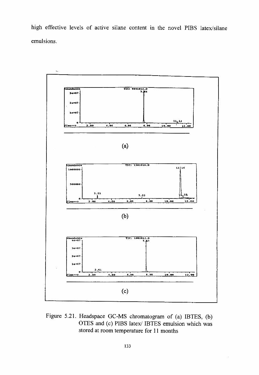
high effective levels of active silane content m the novel PIBS latex/silane
emulsions.
>•+4,
2e+07
le+07
0 1r1->
"°"'nd• nee. 1000000
500000
• :i.oo ... oo
2.00 4.00
TIC: 0101011.D , IW
11~1l
• ,.oo o. oo 10. 00 ' 12.00
(a)
TIC: llO.lOU . D
,.oo 8.00 10 . - 12.00
(b)
(c)
Figure 5.21. Headspace GC-MS chromatogram of (a) IBTES, (b) OTES and ( c) PIBS latex/ IBTES emulsion which was stored at room temperature for 11 months
133
5.2. The stability of novel silane/siloxane emulsions
5.2.1. The stability of PIBS latex/silane emulsions
PIBS latex/silane emulsions are electrostatically stabilised systems. The
electrostatic repulsions between the PIBS particles and the silane droplets
overcome the interparticle attractions between them. The strong repulsion keeps
the emulsion particles apart at a distance where the attraction between them
remains just strong enough to hold them close but is not enough to cause
coalescence. The particles still move freely and individually in the emulsion.
In PIBS latex/silane emulsions, the PIBS latex particles are stabilised by strong
electrostatic force repulsion between the particles (~ 4.3). The electrostatic
repulsion between silane monomer droplets arises from the presence of the
charged PIBS particles and the ionised sulphonate end groups of SDBS which
accumulate at the oil-water interfaces. The presence of the PIBS particles in the
emulsion plays an important role in the stability of the PIBS latex/silane
emulsion. The PIBS particles may prevent the thinning of the liquid film
between the silane droplets. They contribute to the reduction of the interfacial
tension of the system(~ 4.2.2) and lead to high zeta potential (Table 5.1) and a
stabilising effect.
134
5.2.2. The stability of PDMS/silane emulsions
PDMS plays an important role in the stabilisation of this emulsion. In
PDMS/silane emulsions, PDMS and silane form droplets with the aid of amine
soap and adsorb at the surface of the oil droplet. The PDMS droplets and silane
droplets are stabilised by the balance between the van der Waals attractions and
the electrostatic repulsions between oil droplets in combination with the steric
stabilisation effect of the free PDMS molecules in the emulsion. The
electrostatic charge at the surface of the oil droplets results from the presence of
amine soap molecules at the water-oil interface. The layer of ionised carboxyl
groups and the diffuse ion atmosphere of compensating counter ions surrounds
each oil droplet and forms the electrical double layer. The electrostatic repulsion
between oil droplets occurs when their electrical double layers overlap. In the
PDMS/silane emulsion, the electrostatic repulsions between oil droplets are
strong as shown by the relatively high absolute value of the zeta potential of the
emulsion(~ 5.1.2). The steric stabilisation effect in the PDMS/silane emulsion is
caused by the adsorption of PDMS polymer at the surface of the oil droplet.
According to Bass, 137 PDMS has a helical structure in which the siloxane
backbone is flexible and partially ionic. PDMS also exhibits very low
intermolecular attraction. Therefore, the layer of polymeric PDMS adsorbed
around the oil droplet generates a repulsive force when two oil droplets approach
each other through a Brownian encounter. This steric stabilisation effect of the
PDMS contributes to the high freeze-thaw stability of the PDMS/silane
135
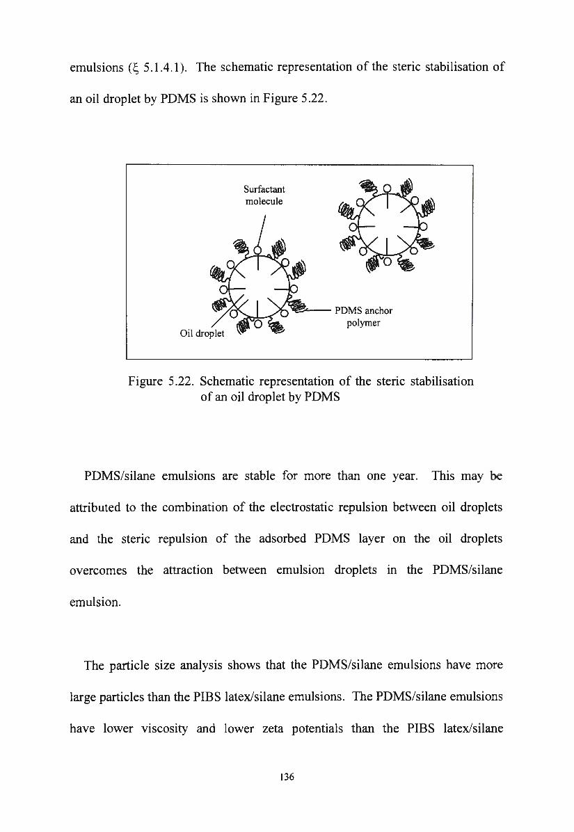
emulsions (~ 5.1.4.l ). The schematic representation of the steric stabilisation of
an oil droplet by PDMS is shown in Figure 5.22.
Surfactant molecule
~- PDMS anchor polymer
Figure 5.22. Schematic representation of the steric stabilisation of an oil droplet by PDMS
PDMS/silane emulsions are stable for more than one year. This may be
attributed to the combination of the electrostatic repulsion between oil droplets
and the steric repulsion of the adsorbed PDMS layer on the oil droplets
overcomes the attraction between emulsion droplets in the PDMS/silane
emulsion.
The particle size analysis shows that the PDMS/silane emulsions have more
large particles than the PIBS latex/silane emulsions. The PDMS/silane emulsions
have lower viscosity and lower zeta potentials than the PIBS latex/silane
136

emulsions. All of these factors indicate that PDMS/silane emulsions may be less
stable than PIBS/silane emulsions during long term storage.
137
CHAPTER SIX
The effectiveness of novel silane/siloxane emulsions for concrete
protection
6.1. Evaluation of the performance of novel emulsions
An evaluation of the performance of the impregnants was conducted in this
study. The performance was examined in terms of the beading effect, the
penetration depth of the impregnants, and the water absorption of the concrete
substrates treated with novel emulsions and hydrocarbon solutions containing the
same concentration of silane. Alkali stability of the impregnants, chloride ion
resistance due to the impregnant and the effect of UV radiation on impregnants
were also tested. The effectiveness of the novel emulsions for concrete
protection was evaluated by a comparison of the results obtained from the
substrates treated with novel emulsions with those obtained from the substrates
treated with silane solutions in organic solvent.
6.2. The application mechanism of silane/siloxane emulsions
When a silane/siloxane emulsion is applied to a concrete substrate, several
reactions simultaneously occur:
(a) the emulsion breaks, 138 and siloxane, silane and water are absorbed into the
concrete substrate by capillary suction;
138
(b) a polysiloxane film is formed on the concrete surface; 139
( c) the silane partially evaporates;
( d) silane molecules react with each other and with the concrete substrate.
As soon as the emulsion spreads over the concrete surface, emulsion
ingredients are absorbed into the concrete. The absorption of the silane and water
into the concrete substrate by capillary forces is the fastest reaction compared to
the absorption of the polysiloxane due to their small molecular weight and high
spreadability. The second fastest reaction is the formation of the polysiloxane
film (from PIBS particles or PDMS droplets) on the concrete surface. The
hydrolysis of the monomeric alkylalkoxysilane, followed by the subsequent
condensation reaction of silanol intermediates in the capillaries and pores inside
the concrete substrate is very slow and may take days to be completed. The
evaporation of the silane during application is the slowest reaction. The
evaporation of the silane may occur faster than the condensation reaction only
under unfavourable application conditions such as low humidity, high winds
and/or high temperature. High temperature, whilst promoting evaporation, also
speeds up the condensation of silanols into oligomeric siloxanes and accelerates
film forming of the polysiloxane on the concrete surface. This will significantly
reduce the evaporation of the silane inside the capillaries and pores to the treated
surface. It has been shown by the work of McGettigan, 140 that the loss of high
boiling silane due to evaporation, even under unfavourable application conditions
139
is so minimal that it can be ignored in field application. The absorption of the
polysiloxane into the concrete substrate is much slower than the absorption of
silane due to its high molecular weight. Therefore, most of the polysiloxane
remains on the treated surface and this will have a beneficial effect on the
beading effect of the treated concrete.
The loss of water either by absorption into the concrete substrate or
evaporation into the atmosphere causes the suspended polysiloxane particles (or
droplets) to become crowded together to form a hydrophobic film on the treated
surface. Film formation is a complex process and the mechanism of film
formation has not been completely elucidated. The earliest theory of film
formation was developed by Dillon et al. 141 According to this theory, the main
energy required for particle coalescence is produced by surface tension forces as
the total surface area decreases. The theory uses Frenkel's equation: 142
82 = 3yt/2nrir (6.1)
where e is the half-angle of coalescence (Figure 6.1 ), y is the surface tension, r is
the particle radius and Tl is the particle viscosity. 82 was determined as a function
of particle radius r. Equation 6.1 shows that the pressure related to 8 on the
particles varies inversely with the polymer particle radius.
140

An alternative theory according to Brown 143 postulated that polymer particles
would coalesce if the driving force provided by capillary pressure is sufficient to
overcome the resistance of the particles to deformation. The nature of the forces
involved in the coalescence of the particles is shown in Figure 6.2. According to
this theory, the maximum modulus for film formation depends inversely on the
particle radius r.
'\. \ i I
/ .......... .-~
+--__.
/ ~
! i i \
Figure 6.1. Coalescence of spherical particles by viscous flow caused by surface tension forces
Figure 6.2. Coalescence of spherical particles caused by capillary forces
141
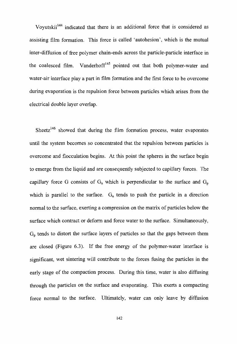
Voyutskii 144 indicated that there is an additional force that is considered as
assisting film formation. This force is called 'autohesion' , which is the mutual
inter-diffusion of free polymer chain-ends across the particle-particle interface in
the coalesced film. Vanderhoff145 pointed out that both polymer-water and
water-air interface play a part in film formation and the first force to be overcome
during evaporation is the repulsion force between particles which arises from the
electrical double layer overlap.
Sheetz146 showed that during the film formation process, water evaporates
until the system becomes so concentrated that the repulsion between particles is
overcome and flocculation begins. At this point the spheres in the surface begin
to emerge from the liquid and are consequently subjected to capillary forces. The
capillary force G consists of G0 which is perpendicular to the surface and GP
which is parallel to the surface. G0 tends to push the particle in a direction
normal to the surface, exerting a compression on the matrix of particles below the
surface which contract or deform and force water to the surface. Simultaneously,
Gp tends to distort the surface layers of particles so that the gaps between them
are closed (Figure 6.3). If the free energy of the polymer-water interface is
significant, wet sintering will contribute to the forces fusing the particles in the
early stage of the compaction process. During this time, water is also diffusing
through the particles on the surface and evaporating. This exerts a compacting
force normal to the surface. Ultimately, water can only leave by diffusion
142
through the particles as the compaction grows and the compressive pressure
compacts the polymer film with no void spaces. After compression, the
interfaces remain intact and it takes several days before the final equilibrium is
reached as either the adsorbed surfactants congregate together if there is a large
surplus of surfactant or become dispersed evenly throughout the film where only
a small quantity of surfactant has been used.
Capillary
Figure 6.3. Schematic representation of the capillary force
The rate of film formation depends on the water absorption rate of the
substrate, the quantity of emulsion, the temperature, the type of surfactant, and
the particle size of the emulsion. If the water absorption rate is slow, it may
allow polysiloxane particles or droplets to have sufficient time to assume
optimum packing and, therefore, maximum binding and film integration. If the
water absorption rate is fast, or if the size of the capillaries or pores of the
143
concrete substrate are greater than the emulsion droplets, it is probable that the
emulsion will quickly impregnate the substrate, leaving a weak or poorly
integrated film on the surface. Increases in temperature will accelerate the
evaporation rate of water and silane whilst only slightly affecting the diffusion
rate of water and silane through the polysiloxane film. During the film forming
process, surfactants will not only remain at the film surface, but also migrate into
the concrete substrate where they could interfere with wet adhesion of the film.
The particle size of the emulsion plays a major role in film formation and
integration according to the theories developed by Dillon et al. 141 and Brown. 143
Both these theories imply that the pressure on the particles to coalesce increases
with small particles. Emulsions with small polymer particles will produce films
where the particles are more closely packed. Water and silane must diffuse
through a continuous surface film to evaporate. The rate of diffusion through the
surface film is slower than the rate of evaporation at the air-emulsion interface.
Therefore the film formation will effectively reduce the evaporation of
alkylalkoxysilane under the PIBS film.
6.3. Factors affecting the performance of silane/siloxane emulsions
The effectiveness of silane/siloxane emulsions for the protection of reinforced
concrete depends on a number of factors such as the choice of the silane, the
stability of the silane in the emulsion and the effect of surfactant on the beading
effect exhibited by the treated concrete.
144
The choice of the silane plays an important role in the performance of
silane/siloxane emulsions as it has a great influence on the water repellency and
the alkali stability of the impregnant m the treated concrete.
Isobutyltriethoxysilane (IBTES) and octyltriethoxysilane (OTES) have been
chosen as the active ingredients in the novel silane/siloxane emulsions. The
reasons for choosing IBTES and OTES are due to (a) their low volatility and
therefore the loss of the silane during application is minimised, (b) the rate of
hydrolysis of IBTES and OTES in an aqueous medium is very slow compared to
alkyltrimethoxysilanes, 147 ( c) their high degree of water repellency (~ 6.4) and
good resistance to hydroxide attack (~ 6.5) due to the isobutyl and octyl group,
( d) their small molecular size in a comparison to the capillaries and pores in
concrete148 and (e) their commercial availability.
In silane/siloxane emulsions, the alkylalkoxysilane is hydrolysable. In an
acidic or basic aqueous medium, the hydrolysis of the alkoxy group occurs and
alcohol is produced. Therefore, if the pH of the emulsion is not neutral, the
active silane may hydrolyse to silanol and polymerise. As a result, the silane
content in the emulsion would be reduced during storage. The pH of the novel
silane/siloxane emulsions were maintained at pH~ 7 without the use of a buffer.
Test results(~ 5.1.5) showed that the silane remained substantially unhydrolysed
and its concentration in the emulsions was not changed during storage for many
months. In the PIBS latex, the surfactant SDBS is a wetting agent. The PIBS
145
latex was cleaned in a purification process before use in making PIBS latex/silane
emulsions and thus the concentration of "free" SDBS in the final emulsions was
very low. The remaining SDBS in the PIBS latex/silane emulsion has little effect
on the treated concrete (as shown in 6.3 and 6.4). The hydrophobic layer under
the very surface of the concrete treated with the novel emulsions was not wetted
when the "impregnated part" of the cross-section of the treated specimen was
immersed in water. This indicates that the SDBS surfactant and amine soap
when used at low concentration, caused no "wetting effect" at the very surface of
the treated concrete.
The combination of alkylalkoxysilane and polysiloxane used to make novel
emulsions has some advantages. Firstly, a high penetration depth was achieved
due to the low molecular weight of the silane. Secondly, a satisfactory early
water repellency was achieved due to the fast film-forming of the polysiloxane on
the treated surface. Thirdly, the use of the polysiloxane makes the emulsification
of the silane easier and a determination of the optimum HLB value at which the
silane may be emulsified becomes unnecessary.
6.4. The beading effect and the penetration depth of the water repellent
The beading effect and the penetration depth of the impregnant for the treated
concrete blocks is shown in Table 6.1. The penetration depths of the emulsions
are lower than that of the solutions. This can be explained by the presence of the
146
polysiloxane in the emulsions. Some PIBS particles in the emulsions would have
an average diameter of over 10 nm and are larger than the concrete gel pores
which have an average diameter of 1.5-2.0 nm. 148 Therefore, when the emulsion
is applied onto the concrete substrate, the emulsion breaks and some of
polysiloxane remains on the surface of the concrete substrate.
The lower penetration depth of the emulsions may also be attributed to the
lower spreadability of the emulsion compared to the silane solution. According
to Washburn, 149 the rate at which a liquid will rise in a vertical cylindrical
capillary of a solid substrate, assuming the absence of wall slippage effects is
shown by:
dh/dt = r(ycos8-ghp)/411h (6.2)
where dh/dt is the rate of penetration into capillaries, h is the height of rise in
time t, y is the surface tension of the liquid, r is the radius of the capillary, e is the
contact angle, g is the gravitational constant, p = p1-p2 is the difference in density
between the rising liquid (p1) and the surrounding fluid (p2) and Tl is the viscosity
of the liquid. Equation (6.2) shows that the rate of penetration of a liquid into a
capillary depends on the viscosity of the liquid. The viscosity of the emulsion is
higher than that of the hydrocarbon solvent in silane solution. Therefore, the
147
emulsion exhibits less spreadability than the silane solution. As a result, the
penetration depth of the emulsions is lower than that of the silane solutions.
Impregnants Concentration of Penetration depth Beading effect silane (%by (mm)
weight)
IBTES solution 40% 6.5 3 20% 3.5 3
PIBS latex/IBTES 40% 6.0 3 emulsion 20% 3.0 3
PDMS/IBTES emulsion 40% 5.5 2 20% 2.8 2
OTES solution 40% 6.0 2 20% 3.0 2
PIBS latex/OTES 40% 5.5 2 emulsion 20% 2.8 2
PDMS/OTES emulsion 40% 5.0 I 20% 2.5 I
Table 6.1. The beading effect and penetration depth for the treated concrete blocks
The penetration depth also depends on the nature of the alkyl group of the
active alkylalkoxysilane. The larger the alkyl group, the lower the penetration
depth obtained. This is shown by the penetration depth in concrete treated with
silane solutions and emulsions. Therefore, octyltriethoxysilane emulsions with
an eight carbon alkyl group exhibit a lower penetration depth than those of
isobutyltriethoxysilane emulsions with a four carbon alkyl group. The
penetration depth increases with an increase in silane concentration. The beading
effect of the PIBS latex/IBTES emulsions is similar to the solutions containing
the same concentration of the silane in hydrocarbon solvent (Table 6.1 ).
148
The molecular weight of the siloxane has an effect on the penetration depth of
the silane/siloxane emulsions. The penetration depth of PDMS/silane emulsions
with PDMS having a molecular weight of 13,650 is lower than the penetration
depth of the PIBS latex/silane emulsions in which the molecular weight of the
PIBS particles lie in the range between 800 and 4,000. The beading effect of the
treated concrete with PDMS/silane emulsions is better than the concrete treated
with silane solutions or PIBS latex/silane emulsions. This indicates that the
presence of the silicone fluid and amine soap at the surface of the concrete
increases the beading effect of the treated substrates. The PDMS/silane
emulsions provide a better beading effect than PIBS latex/silane emulsions due to
the effect of the surfactant remaining on the surface. In the PIBS latex/silane
emulsions, SDBS is a wetting agent, whilst the amine soap of oleic acid in the
PDMS/silane emulsions is a deactivatable surfactant. Following treatment of the
concrete, the amine soap decomposes as the morpholine or ammonia evaporates
and leaves the hydrophobic oleic acid on the concrete surface. However, any
SDBS in the PIBS latex/silane emulsion remains on the treated surface and
decreases the beading effect.
The penetration depth in mortar discs is higher than the depth in concrete
substrates (Table 6.2). This indicates that the penetration depth depends largely
on the compaction of the substrate and the resultant capillary and pore size.
149

Impregnants Concentration of Penetration depth Beading effect silane (%by (mm)
weight) IBTES solution in 40% 12.0 3
hydrocarbon 20% 8.5 3 PIBS latex/IBTES 40% 11.0 3
emulsion 20% 7.5 3 PDMS/IBTES emulsion 40% 9.0 2
20% 6.5 2 OTES solution in 40% 9.0 2
hydrocarbon 20% 7.0 2 PIBS latex/OTES 40% 7.0 2
emulsion 20% 6.5 2
Table 6.2. The beading effect and penetration depth for the treated mortar discs
6.5. Water absorption of the treated concrete
Figure 6.4 represents the relationship between the time of water absorption test
and the percentage weight gain of the treated and untreated concrete over 35 days
for isobutyltriethoxysilane solution and emulsion. The water absorption of the
untreated concrete increases sharply during one day, then slows down and
becomes nearly constant after 7 days. The water absorption performance of
concrete substrates treated with IBTES solution and PIBS latex/IBTES emulsion
exhibit very similar characteristics to each other. Figure 6.5 shows that the water
absorption performance characteristics of the IBTES emulsions are superior to
the IBTES solution of the same concentration of isobutyltriethoxysilane. This
may be attributed to the formation of polysiloxane film on the surface of the
concrete treated with emulsion and the filling of the larger pores in the surface
layer of the treated concrete by PIBS particles or PDMS.
150
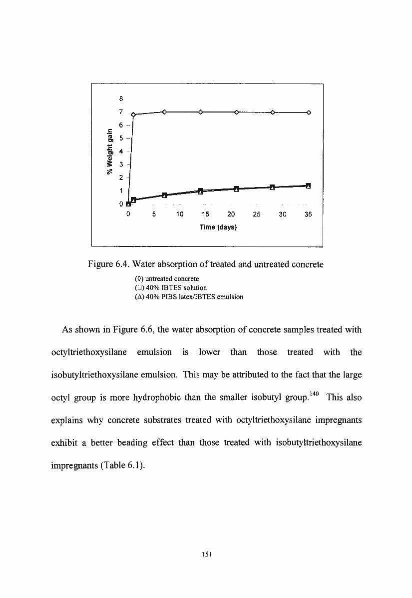
8
7 -
6 -c I'll 5 -C> -.c 4 ~ C> ·a; 3: 3 ~ 0
2
1
0 0 5 10 15 20 25 30 35
Time (days)
Figure 6.4. Water absorption of treated and untreated concrete
(0) untreated concrete (0) 40% IBTES solution (~) 40% PIBS latex/IBTES emulsion
As shown in Figure 6.6, the water absorption of concrete samples treated with
octyltriethoxysilane emulsion 1s lower than those treated with the
isobutyltriethoxysilane emulsion. This may be attributed to the fact that the large
octyl group is more hydrophobic than the smaller isobutyl group. 140 This also
explains why concrete substrates treated with octyltriethoxysilane impregnants
exhibit a better beading effect than those treated with isobutyltriethoxysilane
impregnants (Table 6.1 ).
151
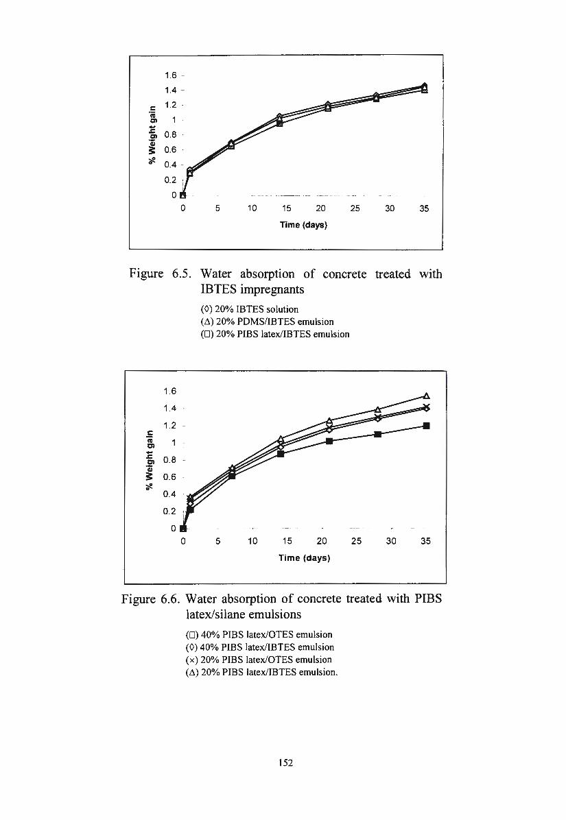
1.6 -
1.4 -
c: 1.2 -
'iii Cl -&. 0.8 Cl
'Qi 3: 0.6 ~ 0 0.4 -
0.2 T
0 0 5 10 15 20 25 30 35
Time (days)
Figure 6.5. Water absorption of concrete treated with IBTES impregnants
(0) 20% IBTES solution (M 20% PDMS/IBTES emulsion (0) 20% PIBS latex/IBTES emulsion
1.6
1.4
c: ·; C> -&. 0.8 C> ·c; 3: 0.6 ~ 0
0.4
0.2
0 0 5 10 15 20 25 30 35
Time (days)
Figure 6.6. Water absorption of concrete treated with PIBS latex/silane emulsions
(0) 40% PIBS latex/OTES emulsion (0) 40% PIBS latex/IBTES emulsion ( x) 20% PIBS latex/OTES emulsion ('1.) 20% PIBS latex/IBTES emulsion.
152
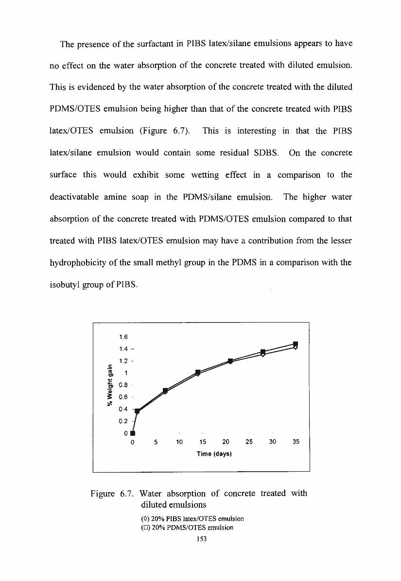
The presence of the surfactant in PIBS latex/silane emulsions appears to have
no effect on the water absorption of the concrete treated with diluted emulsion.
This is evidenced by the water absorption of the concrete treated with the diluted
PDMS/OTES emulsion being higher than that of the concrete treated with PIBS
latex/OTES emulsion (Figure 6.7). This is interesting in that the PIBS
latex/silane emulsion would contain some residual SOBS. On the concrete
surface this would exhibit some wetting effect in a comparison to the
deactivatable amine soap in the PDMS/silane emulsion. The higher water
absorption of the concrete treated with PDMS/OTES emulsion compared to that
treated with PIBS latex/OTES emulsion may have a contribution from the lesser
hydrophobicity of the small methyl group in the PDMS in a comparison with the
isobutyl group of PIBS.
1.6 -
1.4 -
c: Cll c:n -.c: c:n ·; 3: ~ 0
0.2
0 0 5 10 15 20 25 30 35
Time (days)
Figure 6.7. Water absorption of concrete treated with diluted emulsions
(0) 20% PIBS latex/OTES emulsion (0) 20% PDMS/OTES emulsion
153
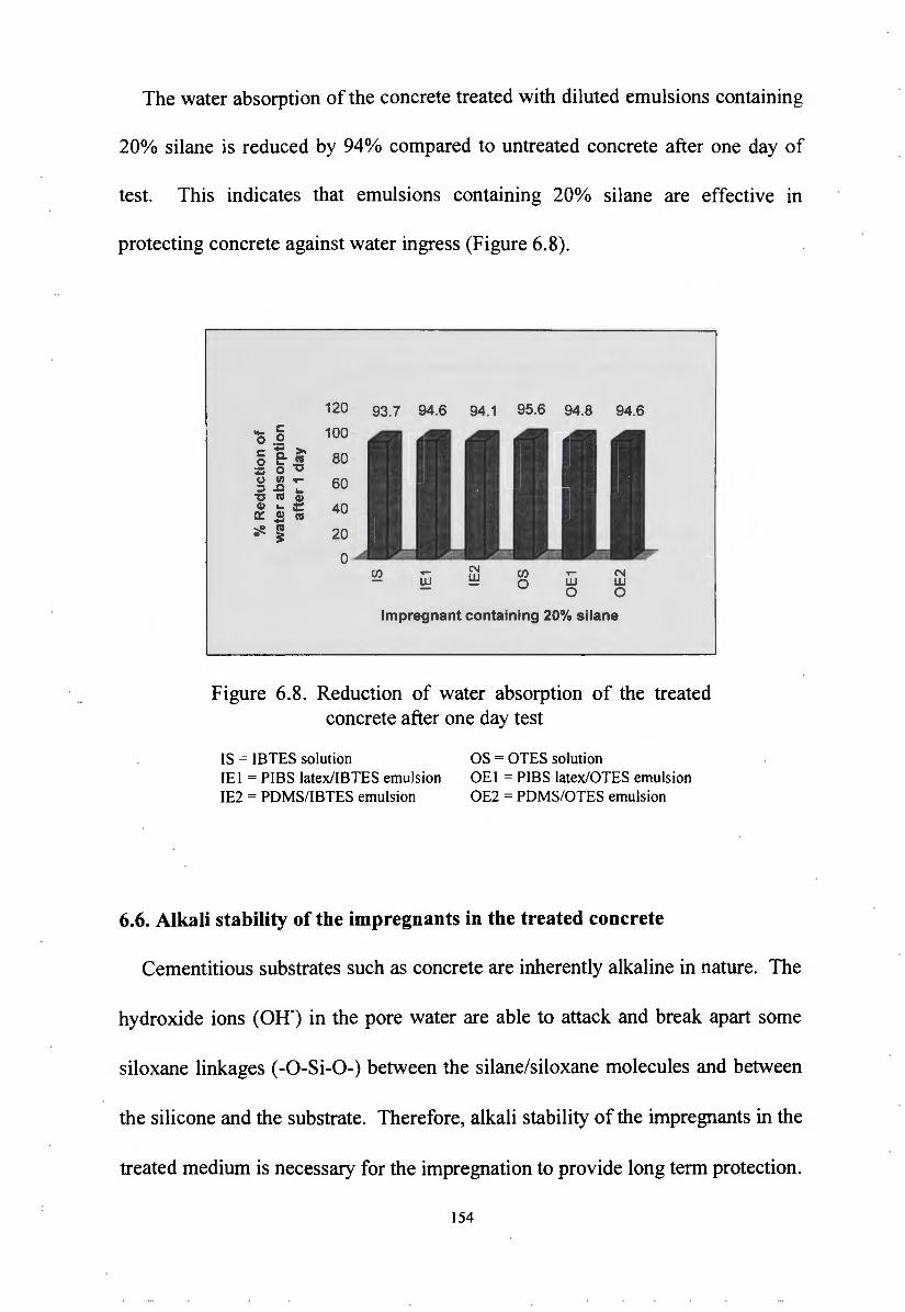
The water absorption of the concrete treated with diluted emulsions containing
20o/o silane is reduced by 94% compared to untreated concrete after one day of
test. This indicates that emulsions containing 20% silane are effective in
protecting concrete against water ingress (Figure 6.8).
120 93.7 94.6 94.1 95.6 94.8 94.6 -c: 100 0 .2 c: ... >-
80 0 e- cu ; 0 "C (,,) Ill ..... 60 ::I .c ...
"C cu Q) Q) ... :::
a::: .s cu 40 ~ cu 0 ~ 20
0 (/) ...... N (/) ...... N
UJ UJ 0 UJ UJ 0 0
lmpregnant containing 20% silane
Figure 6.8. Reduction of water absorption of the treated concrete after one day test
IS = IBTES solution OS = OTES solution IEI = PIBS latex/IBTES emulsion OEI = PIBS latex/OTES emulsion IE2 = PDMS/IBTES emulsion OE2 = PDMS/OTES emulsion
6.6. Alkali stability of the impregnants in the treated concrete
Cementitious substrates such as concrete are inherently alkaline in nature. The
hydroxide ions (OH-) in the pore water are able to attack and break apart some
siloxane linkages (-0-Si-O-) between the silane/siloxane molecules and between
the silicone and the substrate. Therefore, alkali stability of the impregnants in the
treated medium is necessary for the impregnation to provide long term protection.
154
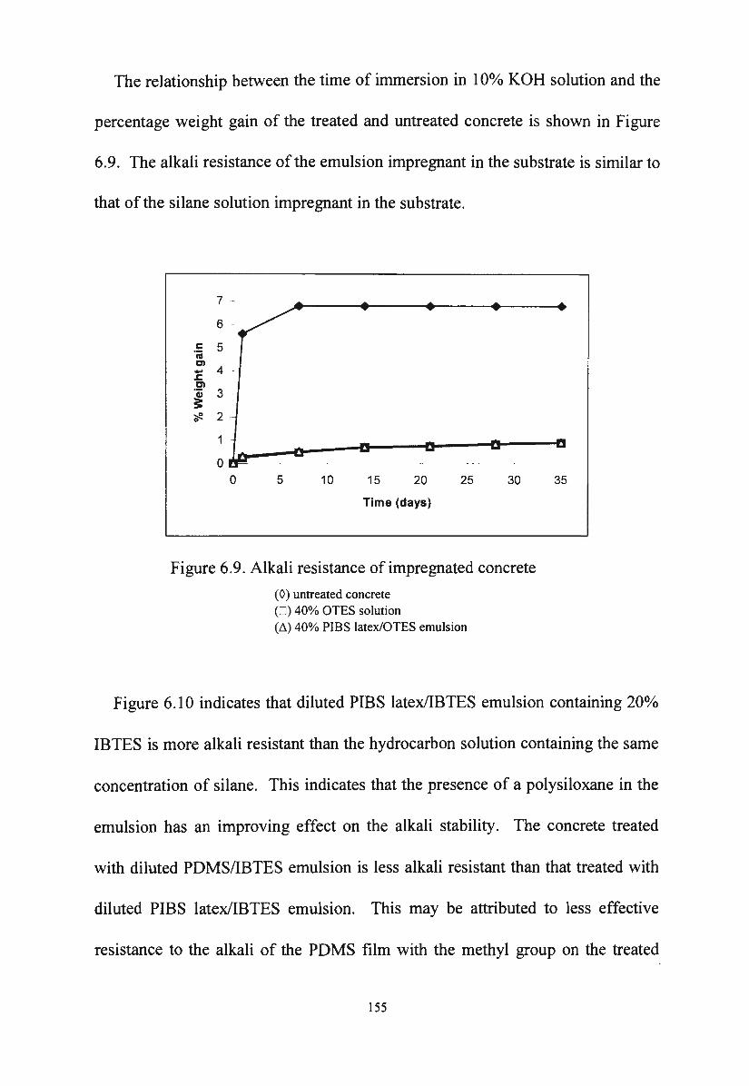
The relationship between the time of immersion in 10% KOH solution and the
percentage weight gain of the treated and untreated concrete is shown in Figure
6.9. The alkali resistance of the emulsion impregnant in the substrate is similar to
that of the silane solution impregnant in the substrate.
7 ~
6 -
.!: 5 cu C>
- 4 .c: Cl ·a; 3 3: ';fe. 2
0 0 5 10 15 20 25
Time (days)
30
Figure 6.9. Alkali resistance of impregnated concrete
( 0) untreated concrete (0 ) 40% OTES solution (~) 40% PIBS latex/OTES emulsion
35
Figure 6.10 indicates that diluted PIBS latex/IBTES emulsion containing 20%
IBTES is more alkali resistant than the hydrocarbon solution containing the same
concentration of silane. This indicates that the presence of a polysiloxane in the
emulsion has an improving effect on the alkali stability. The concrete treated
with diluted PDMS/IBTES emulsion is less alkali resistant than that treated with
diluted PIBS latex/IBTES emulsion. This may be attributed to less effective
resistance to the alkali of the PDMS film with the methyl group on the treated
155
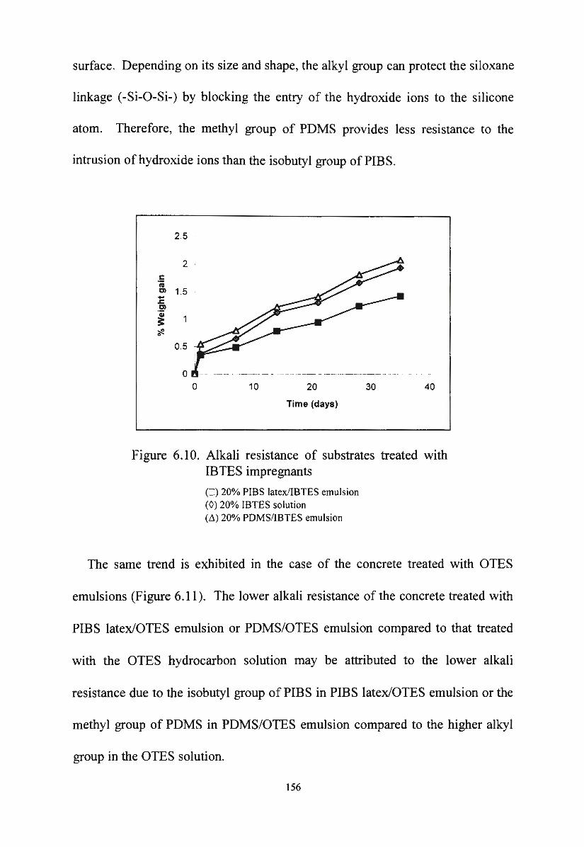
surface. Depending on its size and shape, the alkyl group can protect the siloxane
linkage (-Si-0-Si-) by blocking the entry of the hydroxide ions to the silicone
atom. Therefore, the methyl group of PDMS provides less resistance to the
intrusion of hydroxide ions than the isobutyl group of PIBS.
2.5
2 c 'iii C'I 1.5 -~ C'I ·a; ~ ~ 0
0.5
0
-
0 10 20
Time (days)
30 40
Figure 6.10. Alkali resistance of substrates treated with IBTES impregnants
(D) 20% PIBS latex/IBTES emulsion (0) 20% IBTES solution (~) 20% PDMS/IBTES emulsion
The same trend is exhibited in the case of the concrete treated with OTES
emulsions (Figure 6.11 ). The lower alkali resistance of the concrete treated with
PIBS latex/OTES emulsion or PDMS/OTES emulsion compared to that treated
with the OTES hydrocarbon solution may be attributed to the lower alkali
resistance due to the isobutyl group of PIBS in PIBS latex/OTES emulsion or the
methyl group of PDMS in PDMS/OTES emulsion compared to the higher alkyl
group in the OTES solution.
156
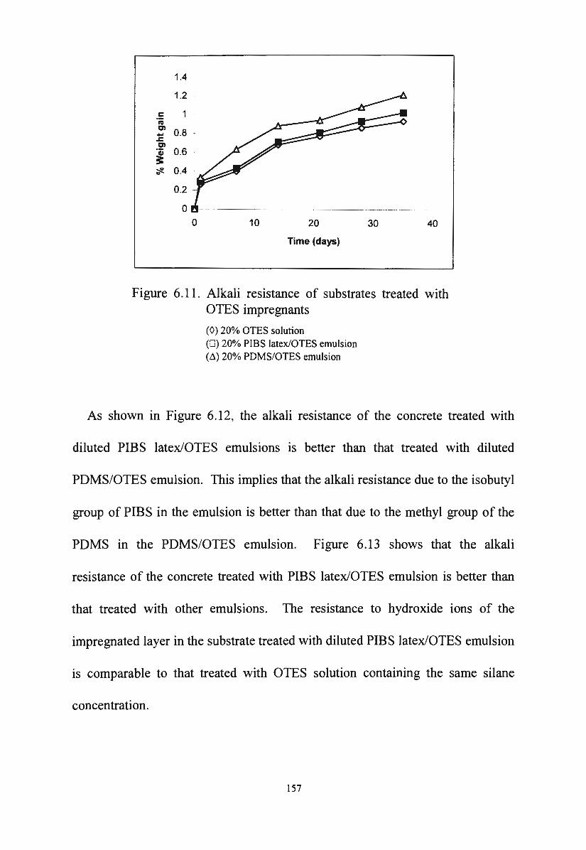
.5 nl en ...
.t::. en
~
1.4
-.;e. 0.4
0.2
0 0 10 20
Time (days)
30 40
Figure 6.11. Alkali resistance of substrates treated with OTES impregnants
(0) 20% OTES solution (0 ) 20% PIBS latex/OTES emulsion (~) 20% PDMS/OTES emulsion
As shown in Figure 6.12, the alkali resistance of the concrete treated with
diluted PIBS latex/OTES emulsions is better than that treated with diluted
PDMS/OTES emulsion. This implies that the alkali resistance due to the isobutyl
group of PIBS in the emulsion is better than that due to the methyl group of the
PDMS in the PDMS/OTES emulsion. Figure 6.13 shows that the alkali
resistance of the concrete treated with PIBS latex/OTES emulsion is better than
that treated with other emulsions. The resistance to hydroxide ions of the
impregnated layer in the substrate treated with diluted PIBS latex/OTES emulsion
is comparable to that treated with OTES solution containing the same silane
concentration.
157
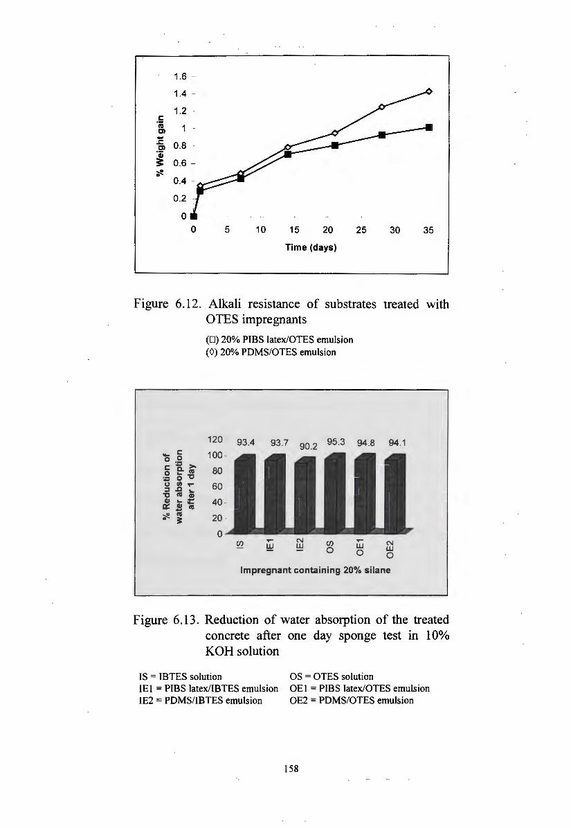
1.6 -
1.4 -
1.2 c: ·;
1 C) -.c: 0.8 -C) ·a; ;:: 0.6 -~ 0
0.4 -
0.2
0
0 5 10 15 20 25 30 35
Time (days)
Figure 6.12. Alkali resistance of substrates treated with OTES impregnants
.... c: 0 .5:! c: - >-o E- ns +; 0 "C CJ If) ..... ::I .0 ...
"C ns Q)
Q) ... = rx: .! ns ~ ns 0 3:
(D) 20% PIBS latex/OTES emulsion (0) 20% PDMS/OTES emulsion
120 93.4 93.7 95.3 90.2 100 -
80
60
40
20 -
0 (J)
..- N (J) w w 0
94.8 94.1
..- N w 0 w
0
lmpregnant containing 20% silane
Figure 6.13. Reduction of water absorption of the treated concrete after one day sponge test in 10% KOH solution
IS = IBTES solution OS = OTES solution IE I = PIBS latex/IBTES emulsion OE 1 = PIBS latex/OTES emulsion IE2 = PDMS/IBTES emulsion OE2 = PDMS/OTES emulsion
158
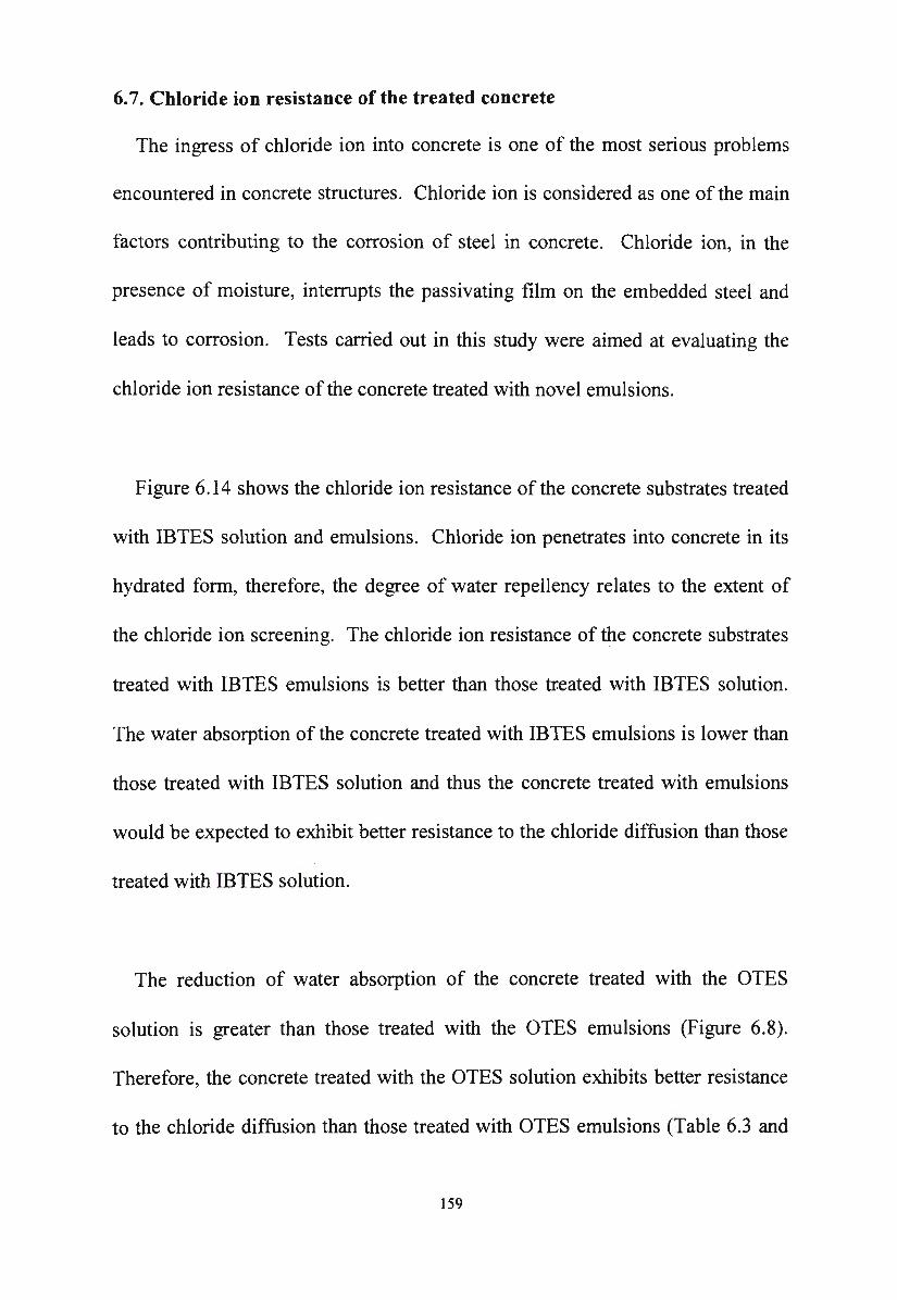
6. 7. Chloride ion resistance of the treated concrete
The ingress of chloride ion into concrete is one of the most serious problems
encountered in concrete structures. Chloride ion is considered as one of the main
factors contributing to the corrosion of steel in concrete. Chloride ion, in the
presence of moisture, interrupts the passivating film on the embedded steel and
leads to corrosion. Tests carried out in this study were aimed at evaluating the
chloride ion resistance of the concrete treated with novel emulsions.
Figure 6.14 shows the chloride ion resistance of the concrete substrates treated
with IBTES solution and emulsions. Chloride ion penetrates into concrete in its
hydrated form, therefore, the degree of water repellency relates to the extent of
the chloride ion screening. The chloride ion resistance of the concrete substrates
treated with IBTES emulsions is better than those treated with IBTES solution.
The water absorption of the concrete treated with IBTES emulsions is lower than
those treated with IBTES solution and thus the concrete treated with emulsions
would be expected to exhibit better resistance to the chloride diffusion than those
treat1ed with IBTES solution.
The reduction of water absorption of the concrete treated with the OTES
solution is greater than those treated with the OTES emulsions (Figure 6.8).
Therefore, the concrete treated with the OTES solution exhibits better resistance
to the chloride diffusion than those treated with OTES emulsions (Table 6.3 and
159
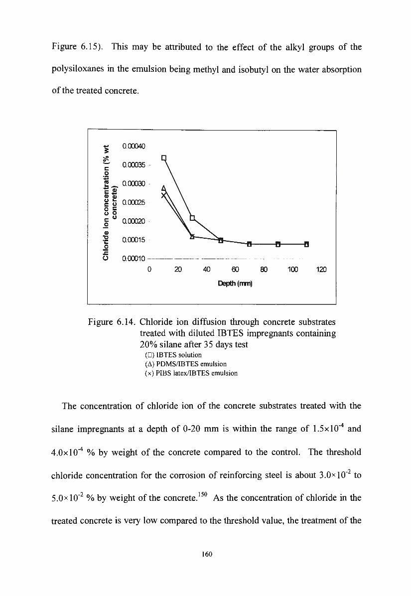
Figure 6.15). This may be attributed to the effect of the alkyl groups of the
polysiloxanes in the emulsion being methyl and isobutyl on the water absorption
of the treated concrete.
O.CID40
~ ~ O.OOJ35 -0 ~ t? _ o.cxmo -~.! Cl) Cl)
g t 0. CXX)25 . 0 c (,,) 0
.2 (,,) 0. CXX)2Q .
Cl) ,, ·c:: .!2 .c ()
O.OOJ15 -
O.OOJ10 - --- -------+---
0 20 40 00 80 100 120
Depth(nm)
Figure 6.14. Chloride ion diffusion through concrete substrates treated with diluted IBTES impregnants containing 20% silane after 3 5 days test
(D) IBTES solution (~) PDMS/IBTES emulsion (x) PIBS latex/IBTES emulsion
The concentration of chloride ion of the concrete substrates treated with the
silane impregnants at a depth of 0-20 mm is within the range of l.5xl0-4 and
4.0x I 0-4 % by weight of the concrete compared to the control. The threshold
chloride concentration for the corrosion of reinforcing steel is about 3.0 x 10⁻² to
5.0x I 0-2 o/o by weight of the concrete. 150 As the concentration of chloride in the
treated concrete is very low compared to the threshold value, the treatment of the
160
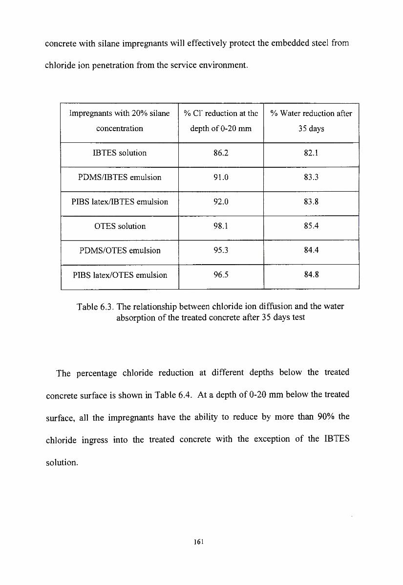
concrete with silane impregnants will effectively protect the embedded steel from
chloride ion penetration from the service environment.
Impregnants with 20% silane % er reduction at the % Water reduction after
concentration depth of 0-20 mm 35 days
IBTES solution 86.2 82.1
PDMS/IBTES emulsion 91.0 83 .3
PIBS latex/IBTES emulsion 92.0 83.8
OTES solution 98.1 85.4
PDMS/OTES emulsion 95.3 84.4
PIBS latex/OTES emulsion 96.5 84.8
Table 6.3. The relationship between chloride ion diffusion and the water absorption of the treated concrete after 3 5 days test
The percentage chloride reduction at different depths below the treated
concrete surface is shown in Table 6.4. At a depth of 0-20 mm below the treated
surface, all the impregnants have the ability to reduce by more than 90% the
chloride ingress into the treated concrete with the exception of the IBTES
solution.
161
'i 0.00)4() .
~ c: o.ocms 0 ;;
,S - O.CXXX30 c: C1I C1I -g ~ O.OOJ25 ·· 0 c: (.) 0 c: (.) .2 0.00J20 ~ C1I
"'C ·~ O.CXXl15 .2 .r:. 0 o.cxxno -
0 20 40 60
Depth(rm1
80 100 120
Figure 6.15. Chloride ion diffusion through concrete substrates treated with diluted OTES impregnants containing 20o/o silane after 35 days test
(0) PDMS/OTES emulsion (~) PIBS latex/OTES emulsion ( x) OTES solution
lmpregnants with 20% silane % er reduction at the
concentration depth of 20 mm
IBTES solution 86.1
PDMS/IBTES emulsion 91.0
PIBS latex/IBTES emulsion 92.0
OTES solution 98.1
PDMS/OTES emulsion 95.3
PIBS latex/OTES emulsion 96.5
% er reduction at the
depth of 40 mm
95.4
97.6
98.7
99.5
98.7
98.7
Table 6.4. The relative reduction of chloride ion in the treated concrete at different depths below the treated surface
162
6.8. The effect of UV radiation on impregnants in the treated concrete
Concrete is exposed to weathering influences and therefore the durability of
the impregnants is also governed by their resistance to the destructive effect of
UV.
The visual appearance of the treated surface before and after 1500 hours of
UV and condensation testing remained similar. The beading effect of all the
treated substrates was significantly decreased after the test as shown in Table 6.5.
This indicates that the destructive effect of UV on the polysiloxane at the surface
of the treated substrate is unavoidable.
Impregnants Beading effect before test Beading effect after test
IBTES solution 3 5
PIBS latex/IBTES emulsion 3 5
PDMS/IBTES emulsion 2 5
OTES solution 2 5
PIBS latex/OTES emulsion 2 5
PDMS/OTES emulsion 1 5
Table 6.5. The beading effect of the treated concrete before and after the UV and condensation weathering test
163
After 1500 hours of the UV and condensation weathering test, the concrete
samples treated with silane impregnants are still capable of reducing by greater
than 90% the water ingress compared to the untreated concrete (Figure 6 .16).
This implies that the UV only has an effect on the polysiloxane layer at the very
surface of the treated substrate, but the hydrophobic polysiloxane layer inside the
treated concrete is unaffected by the destructive effect of the UV.
~ 0
,_ ;: .!! 111 111 "O ~ .... .... ,_ 0 Cl)
c: = 0 111 ; c: CJ 0 ::I ·-
"O .... Cl) e
a:::: 0 VI
.&l 111
120.0
100.0
80 .0
60.0
40.0
20 .0
0.0
93 .7
92 .1
IS
94 .6
93 .0
IE1
94 .1
92 .5
IE2
95 .6
93 .9
OS
94.8
93 .3
OE 1
Im pregnant containing 20% silane
94 .6
92 .9
OE 2
Figure 6.16. Reduction of water absorption of the treated concrete before ( • ) and after ( D ) 1500 hours UV and condensation weathering test
IS = IBTES solution IEI = PIBS latex/IBTES emulsion IE2 = PDMS/IBTES emulsion
OS = OTES solution OE I = PIBS latex/OTES emulsion OE2 = PDMS/OTES emulsion
6.9. Efflorescence resistance of the treated concrete
Efflorescence is a phenomenon in which salt emerges to the concrete surface
causing white surface deposits. As water moves through a concrete structure, it
164
dissolves soluble salts and when it reaches the surface the water evaporates
leaving solid salt efflorescence on the concrete surface. The efflorescence
resistance test on concrete substrates treated with silane impregnants was
conducted over 14 days in a 10% aqueous sodium sulphate solution (~ 3.4.8).
Test results showed that there was no efflorescence on the treated surfaces. This
indicated that the impregnation of concrete with silane solution or silane/siloxane
emulsions interrupts the transport of salts at the boundary between the
impregnated and unimpregnated areas. Water can only move from the
unimpregnated area to the concrete surface in the form of vapour, and therefore,
it cannot carry salts with it. As a result, salts are deposited at the boundary
between impregnated and unimpregnated areas and cannot reach the treated
surface.
165
CHAPTER SEVEN
Conclusions
Novel silane/siloxane emulsions in which alkylalkoxysilanes were the base
material have been developed in this research.
It was found that a stable emulsion could be produced with a composition
containing an alkylalkoxysilane with a polyisobutylsiloxane (PIBS) latex which
was prepared by the emulsion polymerisation of commercial
isobutyltrimethoxysilane. By substituting polyisobutylsiloxane latex with a
commercial silicone fluid, another stable emulsion was formed with an amine
soap as the surfactant. The optimum concentration of alkylalkoxysilane in the
novel emulsions was 40o/o by weight. The concentration of siloxane was varied
depending on the structure, molecular weight of the siloxane, the type and
concentration of the emulsifier. In PIBS latex/silane emulsions, the siloxane was
PIBS latex in which the molecular weight of a cross-linked PIBS was in the range
between 800 and 4000. The preferred concentration of PIBS in PIBS latex/silane
emulsions was about 18% by weight. No further addition of surfactant was
necessary to make the emulsion than that already present in the PIBS latex. The
preferred concentration of a polydimethylsiloxane (PDMS) with a molecular
weight of 13,500 in PDMS/silane emulsions was 10% by weight. The desired
166
surfactant for PDMS/silane emulsions was an amine soap with the concentration
being more than 1 o/o by weight.
Characterisation of the novel emulsions showed that the polysiloxane played
an important role in the formation and the stability of the novel silane/siloxane
emulsions. The polysiloxane increased the stability of the emulsions through
adsorption at the water-oil interface. The use of an organopolysiloxane in the
preparation of silane/siloxane emulsions also made the determination of the
optimum HLB value at which the alkylalkoxysilane can be emulsified
unnecessary and the emulsification process of silanes became more practical.
The polysiloxane improved the beading effect and the water repellency of the
treated concrete when compared to the silane solutions. This was due to the
formation of an hydrophobic film on the treated surface. The polysiloxane also
had a great influence on the viscosity of the novel emulsions.
The emulsion polymerisation of isobutyltrimethoxysilane was a complex
process in which surfactant and the silanol monomer/water ratio played an
important role in the formation and the stability of the polyisobutylsiloxane latex.
These factors also influenced the stability and the performance of the final
polyisobutylsiloxane latex/silane emulsions. The size of the polyisobutylsiloxane
latex particles and the molecular weight of the polyisobutylsiloxane were
controlled effectively by the temperature of the reaction and the suitable
167
concentration of surfactant. This production of a suitable size and molecular
weight polysiloxane for incorporation in the emulsion had a beneficial effect on
film formation when the emulsion was used to treat concrete substrates.
The study of the viscosity of the novel emulsions showed that the novel
emulsions were suitable for impregnating techniques such as spraying, rolling or
brushing. The shear thinning behaviour of concentrated emulsions and the
Newtonian behaviour of the diluted emulsions would have a beneficial effect on
an impregnation operation.
The novel emulsions developed by this research were very stable and had a
long shelf life. They were storable as concentrates for a long period of time. The
efficacy of the novel emulsions was not affected by long term storage. The novel
emulsions maintained a high level of the original silane due to the choice of
silanes with hydrolytic stability.
It was found that the polyisobutylsiloxane latex/silane emulsions performed
marginally better than polydimethylsiloxane/silane emulsions in terms of water
repellency and long term protection of the treated concrete. This may be
attributed to the large isobutyl group of the polyisobutylsiloxane compared to the
small methyl group of polydimethylsiloxane. Although the penetration depth of
the octyltriethoxysilane emulsions was lower than that of the
168
isobutyltriethoxysilane emulsions, the performance of the octyltriethoxysilane
emulsions in general, were much better than the performance of the
isobutyltriethoxysilane emulsions. This may be attributed to the very
hydrophobic octyl group of the octyltriethoxysilane and a high resistance to
hydroxide ion attack due to the steric effect of the octyl group and the insolubility
and hydrophobicity of octyl hydrolysis products.
Diluted emulsions which contained only 20o/o silane were found to be effective
for concrete protection. The performance of the diluted emulsions in terms of
water resistance, alkali stability, UV resistance, efflorescence resistance and
chloride resistance was comparable to organic solvent-based products containing
the same concentration of silane.
169
REFERENCES
1. Gj0rv, O.V., Vennesland, 0. and El-Busaidy, A.H.S., OTC Paper No. 2803
Annu. Offshore Technol. Conj, 8th, (1977).
2. Tremper, B., Beaton, J.L., and Stratfull, R.F., Bulletin No. 182, Highway
Research Board, Washington, D.C., 1958, 18.
3. Browne, R.D., Durability Build. Mater., (Amsterdam), 1982, 1, 113.
4. Calvalier, P.G. and Vassie, Proc. Inst. Civ. Eng. (London), 1981, 70(1), 461.
5. Wiss, Janney, Elstner Associates, Inc., Report No. 840168 (1986), 40.
6. Volkwein, A. and Springenschmid, R., Proc. Int. Conj. Durability Build.
Mater. Compon., 2nd., (1981), U.S. Department of Commerce, NBS
Washington D.C.
7. American Concrete Institute Committee 222, J Am. Coner. Inst., 1985, 11,
3.
8. Shaw, J.D.N., Proceedings of 1st International Conference on Deterioration
and Repair of Reinforced Concrete in the Arabian Gulf, (1985), 127.
9. McCurrich, L.H. and Watkins, T.F., New Civil Engineer, Jan. 1988, 21.
10. Wong, K.H., Weyers, E. and Cady, P.D., Cem. Coner. Res., 1983, 13, 778.
11. Bosch, E., Braunsperger, K., Gluck, H., Pirson, E. and Roth, M., U.S.
Patent 3 956 570 (1976).
170
12. Wittmann, F.H. , Test Report No. 234185/LMC(B) , March 1986, Wacker
Chemie GmbH, Munchen.
13. McGettigan, E. , Coner. Int., June 1992, 52.
14. Weber,H. , in "Fassadenschutz und Bausanierung", (Ed. Weber, H.), Expert
Verlag, Sindelfingen, 1986, 325.
15. Perenchio, W.F., Coner. Int., 1988, 34.
16. Dynamit Nobel, German Patent DE 3 236 628, (1982).
17. Howe, J.P. , Lung, K. and Nile, T., J Organomet. Chem., 1981 , 208, 401 .
18. Comish, A.J. and Lappert, M.F., J Organomet. Chem. , 1984, 271, 153 .
19. Szmant, H.H., Miller, G.W., Makhlouf, J. and Schreiber, K.C., J Org.
Chem. , 1962, 27, 261.
20. George, P.D., Sommer, L.H. and Whitmore, F.C., J Am. Chem. Soc., 1955,
77, 6674.
21. Dutt, P.K., Sci. Cult., 1955, 20, 559.
22. Smith, M.D., Technical Report No. FHWAIOK 86(4) , 1986, Oklahoma
Department of Transportation.
23. Scharnberg, E., "Goldschmidt lnformiert ... ", 64, (1986), 64.
24. Rodder, K.M., "Aqueous Alkylsilane Solutions for Building Protection",
Dynamit Nobel AG, Troisdorf.
25. Schmidt, W., US. Patent 4 517 375 (1985).
26. Li Mao, Master of Applied Science Thesis, Victoria University of
Technology, Melbourne, Australia ( 1995).
171
27. Koerner, G., Nickel, F., Rott, H. and Schmidt, G., US Patent 4 476 282
(1984).
28. Traver, F.J., U.S. Patent 4 529 758 (1985).
29. De Pasquale, R.J. and Wilson M.E., US Patent 4 648 904 (1987) .
30. Wilson, M.E., US Patent 4 877 654 (1989).
31. Plihringer, J.A., US Patent 4 433 013 (1984).
32. Plihringer, J.A., US Patent 4 937 104 (1990).
33. Raleigh, W.J., USPatent4175159(1979).
34. Heaton, T.F., US Patent 5 037 873 (1991).
35 . Fey, K.C., and Freiberg, A.L., US Patent 4 874 431 (1989).
36. Hyde, J.F., and Wehrly, J.R.; US Patent 2 891 920 (1959).
37. Findlay, D.E. and Weyenberg, D.R., US Patent 3 294 725 (1966).
38. Gee, R.P., European Patent 0 459 500 A2 (1991).
39. Scharnberg, E., Koerner, G., Fritsch, H., Grasse, M., and Sucker, R.: US
Patent 5 091 002 ( 1992).
40. Price, C., personal communication.
41. Fliedner, C. personal communication.
42. Goebel, T., Rudolf, M., Harald, A. and Josef, K., German Patent DE 4 122
263 (1993).
43. Mayer, H., Deubzer, B., Iretzberger, P., Mlihlhofer, R. and Wilhelm, H.,
US Patent 4 661 551 ( 1987).
44. Rybczynski, W., Bull. Acad. Sci. Cracovie, 1911, 40.
172

45. Hadamard, J., Compt. Rend., 154, p.1735 (1911).
46. Bancroft, W.D., J Phys. Chem., 1913, 17, 501.
47. Bancroft, W.D., J Phys. Chem., 1915, 19, 275.
48. Harkins, W.D., "The Physical Chemistry of Surface Films", Reinhold,
New York, 1952, 83.
49. Schulman, J.H., and Riley, D.P., J Colloid Sci., 1948, 3, 383.
50. Becher, P., "Emulsion: Theory and Practice", Reinhold, New York, 1957,
96.
51. King, A., Trans. Faraday Soc. , 1941, 37, 168.
52. Schulman, J.H. and Cockbain, E.G., Trans. Faraday Soc., 1940, 36, 651.
53. Kremnev, L.Y.A., Kolloidn. Zh., 1948, 10, 18.
54. Serralach, J.A. and Jones, G., Ind. Eng. Chem., 1931, 23, 1016.
55. Serralach, J.A. and Jones, G., Ind. Eng. Chem., 1933, 25, 816.
56. Biswas, B. and Haydon, D.A., Proc. Int. Congr. Surf Act., 3rd., (1960).
57. Biswas, B. and Haydon, D .A., Kolloid-Z, 1962, 185, 31.
58. Biswas, B. and Haydon, D.A., Kolloid-Z, 1962, 186, 57.
59. Biswas, B. and Haydon, D.A., Proc. R .. Soc. London, 1963, A 271, 296.
60. Nielsen, L.E., Wall, R. and Adams, G., J Colloid Sci., 1958, 13, 441.
61. Lawrence, A.S.C., Nature, (London), 1952, 170, 232.
62. Kitchener, J.A., in "Emulsion Science", (Ed. Sherman, P.), Academic
Press, London, 1968, 120.
173
63. Lyklema, J., "Colloidal Dispersions", (Ed. Goodwin, J.W.), The Royal
Soc. Chem., London, U.K., 1982, 47.
64. Derjaguin, B.V. and Landau, L., Acta Phys. Chim. (USSR), 1941 , 14,
633.
65. Verwey, E.J.W. and Overbeek, J.Th.G., "Theory of the Stability of
Lyophobic Colloids", Elsevier Publishing Co., Amsterdam, 1948, 128.
66. Hamaker, H.C., Physica, 1937, 4, 1058.
67. Sato, T. and Ruch, R., "Stabilisation of Colloidal Dispersions by Polymer
Adsorption", Marcel Dekker, Inc., New York, 1980, 37.
68. Buscall, R., in "Science and Technology of Polymer Colloids - Volume II",
(Eds. Poehlein, G.W., Ottewill, R.H. and Goodwin, J.W.), Martinus Nijhoff
Publishers, 1982, 287.
69. Hunter, R.J., "Zeta Potential m Colloid Science", Academic Press ,
London, 1981.
70. Arya, C.and Newman, J.B., Materials and Structures, Research and
Testing (RILEM, Paris), 1990, 23, 319.
71. Tutti, K., Report No.4 (1982), Swedish Cement and Concrete Research
Institute, Stockholm, 468.
72. Lawrence, C.D., Technical Report No. 544 (1981), British Cement and
Concrete Association, 24.
73. Gonzalez, J.A., Molina, A., Otero, E. and Lopez, W., Mag. Coner. Res.,
1990, 42(150), 23.
174
74. Wallbank, E.J., "The Performance of Concrete in Bridges: A Survey of
200 Highway Bridges", A Report Prepared by G. Maunsell & Partners for
the Department of Transport, HMSO, London, April 1989.
75. Mindless, S. and Young, J.F., "Concrete", Prentice-Hall, New Jersey,
1981, 562.
76. Stratfull, R.F ., Corrosion, 1959, 15, 331.
77. Heuze, B., Materials Protection, Nov. 1965, 57.
78. Gj0rv, O.E., ''Corrosion of Metal in Concrete", Publication SP-49,
American Concrete Institute, Michigan, 1975, 1.
79. Hausmann, D.A., Materials Protection, Oct.. 1969, 23.
80. Rixom, M.R. and Mailvaganam, N.P., "Chemical Admixtures for
Concrete", E.&F.N. Spon., New York, 1986, 141.
81. Edelhauser, H.A., J Polym. Sci., Part C, 1969, 27, 291.
82. Everett, D.H., Gilltepe, M.E. and Wilkinson, M.C., J Colloid Interface
Sci., 1979, 71, 336.
83. McCarvill, W.T. and Fitch, R.M., JColloid Interface Sci., 1978, 64, 403.
84. Vanderhoff, J.W., Van den Hul, H.J., Tausk, R.J.M. and Overbeek,
J.Th.G., in "Clean Surfaces: Their Preparation and Characterisation for
Interfacial Studies", (Ed. Goldfinger, G.), Marcel Dekker, New York, 1970,
15.
175
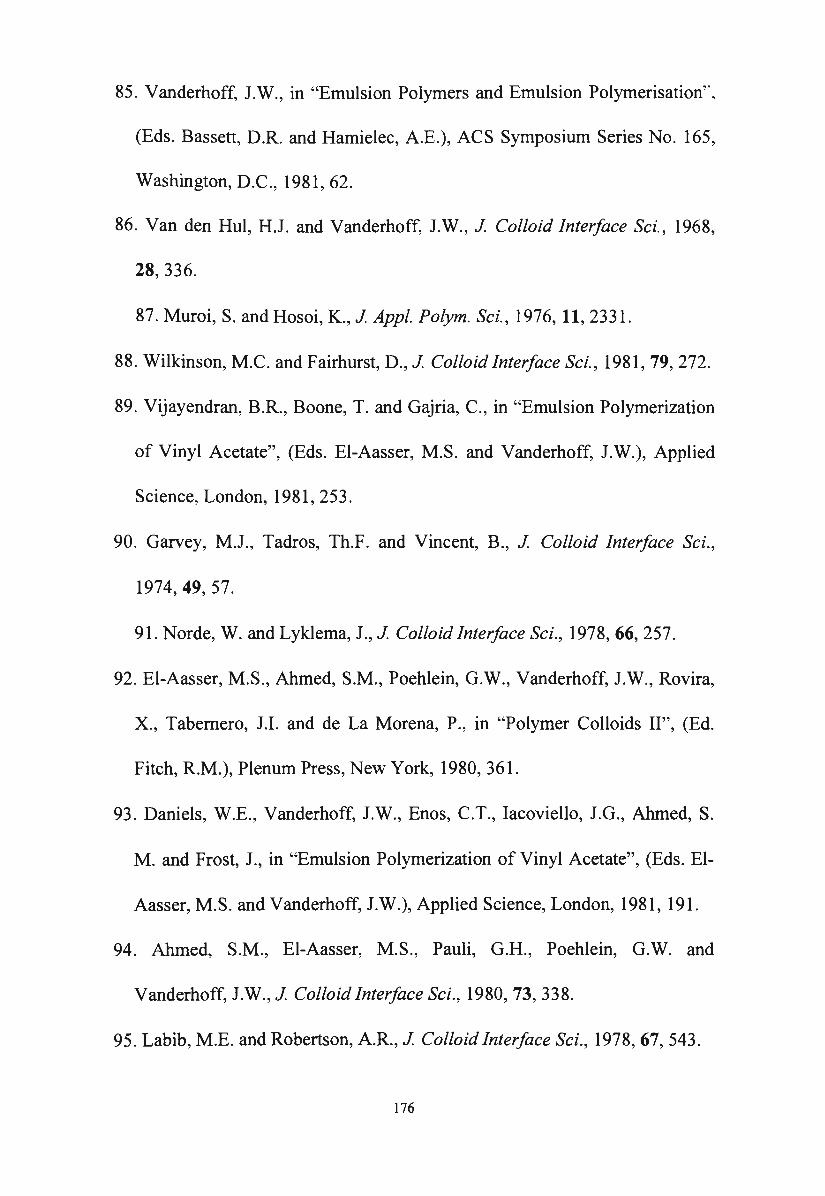
85. Vanderhoff, J.W., in "Emulsion Polymers and Emulsion Polymerisation'",
(Eds. Bassett, D.R. and Hamielec, A.E.), ACS Symposium Series No. 165,
Washington, D.C., 1981, 62.
86. Van den Hul, H.J. and Vanderhoff, J.W., J Colloid Interface Sci., 1968,
28, 336.
87. Muroi, S. and Hosoi, K., J Appl. Polym. Sci., 1976, 11, 2331.
88. Wilkinson, M.C. and Fairhurst, D., J Colloid Interface Sci., 1981, 79, 272.
89. Vijayendran, B.R., Boone, T. and Gajria, C., in "Emulsion Polymerization
of Vinyl Acetate", (Eds. El-Aasser, M.S. and Vanderhoff, J.W.), Applied
Science, London, 1981, 253.
90. Garvey, M.J., Tadros, Th.F. and Vincent, B., J Colloid Interface Sci.,
1974, 49, 57.
91. Norde, W. and Lyklema, J., J Colloid Interface Sci., 1978, 66, 257.
92. El-Aasser, M.S., Ahmed, S.M., Poehlein, G.W., Vanderhoff, J.W., Rovira,
X., Tabernero, J.I. and de La Morena, P., in "Polymer Colloids II'', (Ed.
Fitch, R.M.), Plenum Press, New York, 1980, 361.
93. Daniels, W.E., Vanderhoff, J.W., Enos, C.T., Iacoviello, J.G., Ahmed, S.
M. and Frost, J., in "Emulsion Polymerization of Vinyl Acetate", (Eds. El
Aasser, M.S. and Vanderhoff, J.W.), Applied Science, London, 1981, 191.
94. Ahmed, S.M., El-Aasser, M.S., Pauli, G.H., Poehlein, G.W. and
Vanderhoff, J.W., J Colloid Interface Sci., 1980, 73, 338.
95. Labib, M.E. and Robertson, A.R., J Colloid Interface Sci., 1978, 67, 543.
176
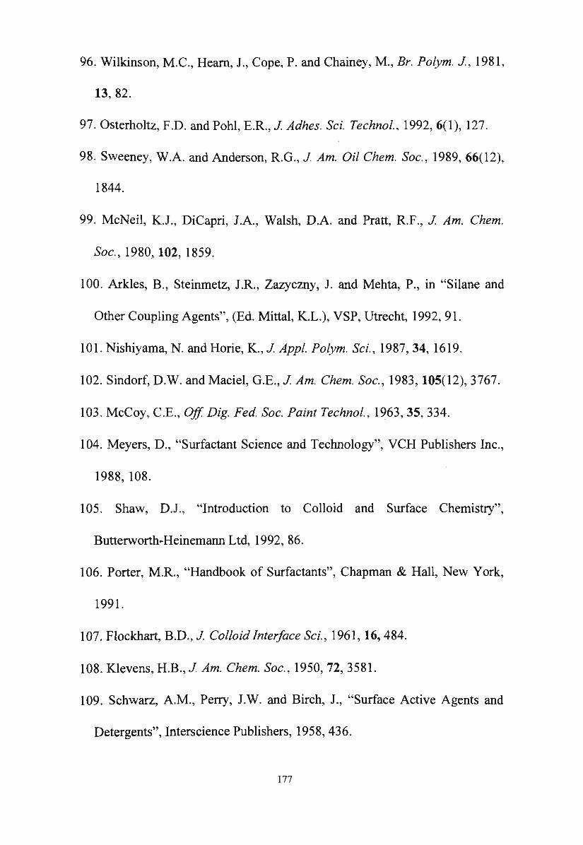
96. Wilkinson, M.C., Heam, J., Cope, P. and Chainey, M., Br. Polym. J , 1981 ,
13, 82.
97 . Osterholtz, F.D. and Pohl, E.R., J Adhes. Sci. Technol., 1992, 6(1), 127.
98. Sweeney, W.A. and Anderson, R.G. , J Am. Oil Chem. Soc., 1989, 66(12),
1844.
99. McNeil, K.J. , DiCapri, J.A., Walsh, D.A. and Pratt, R.F., J Am. Chem.
Soc., 1980, 102, 1859.
100. Arkles, B., Steinmetz, J.R., Zazyczny, J. and Mehta, P. , in "Silane and
Other Coupling Agents", (Ed. Mittal, K.L.), VSP, Utrecht, 1992, 91.
101. Nishiyama, N. and Horie, K., J Appl. Polym. Sci., 1987, 34, 1619.
102. Sindorf, D.W. and Maciel, G.E. , J Am. Chem. Soc., 1983, 105(12), 3767.
103. McCoy, C.E., Off Dig. Fed. Soc. Paint Technol. , 1963, 35, 334.
104. Meyers, D., "Surfactant Science and Technology", VCH Publishers Inc.,
1988, 108.
105. Shaw, D.J., "Introduction to Colloid and Surface Chemistry",
Butterworth-Heinemann Ltd, 1992, 86.
106. Porter, M.R., "Handbook of Surfactants", Chapman & Hall, New York,
1991.
107. Flockhart, B.D., J Colloid Interface Sci. , 1961, 16, 484.
108. Klevens, H.B ., J Am. Chem. Soc. , 1950, 72, 3581.
109. Schwarz, A.M., Perry, J.W. and Birch, J., "Surface Active Agents and
Detergents'', lnterscience Publishers, 1958, 436.
177
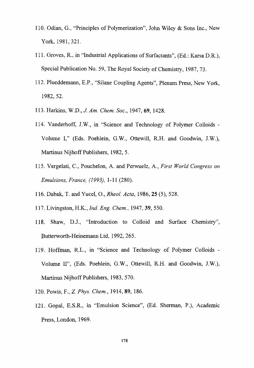
110. Odian, G., "Principles of Polymerization", John Wiley & Sons Inc., New
York, 19 81, 3 21.
111. Groves, R., in "Industrial Applications of Surfactants", (Ed.: Karsa D.R.),
Special Publication No. 59, The Royal Society of Chemistry, 1987, 73.
112. Plueddemann, E.P., "Silane Coupling Agents", Plenum Press, New York,
1982, 52.
113. Harkins, W.D., J Am. Chem. Soc., 1947, 69, 1428.
114. Vanderhoff, J.W., in "Science and Technology of Polymer Colloids -
Volume I," (Eds. Poehlein, G.W., Ottewill, R.H. and Goodwin, J.W.),
Martinus Nijhoff Publishers, 1982, 5.
115. Vergelati, C., Pouchelon, A. and Perwuelz, A., First World Congress on
Emulsions, France, (1993), 1-11 (280).
116. Dabak, T. and Yucel, 0., Rheol. Acta, 1986, 25 (5), 528.
117. Livingston, H.K., Ind. Eng. Chem., 1947, 39, 550.
118. Shaw, DJ., "Introduction to Colloid and Surface Chemistry",
Butterworth-Heinemann Ltd, 1992, 265.
119. Hoffman, R.L., in "Science and Technology of Polymer Colloids -
Volume II", (Eds. Poehlein, G.W., Ottewill, R.H. and Goodwin, J.W.),
Martinus Nijhoff Publishers, 1983, 570.
120. Powis, F., Z. Phys. Chem., 1914, 89, 186.
121. Gopal, E.S.R., in "Emulsion Science", (Ed. Sherman, P.), Academic
Press, London, 1969.
178

122. Vermeulen, T., Williams, G.M. and Langlois, G.E. , Chem. Eng. Progress,
1955, 51, 85.
123. Rodger, W.A., Trice, V.G. and Rushton, J.H., Chem. Eng. Progress,
1956, 52, 515.
124. Pavlushenko, I.S. and Yanishevskii, A.V., Chem. Abstr. , 1959, 53,
19479f.
125. Landau, J. and Prochzka, J., Collect. Czech. Chem. Commun., 1964, 29,
1866.
126. Woodbridge, R. , in "Principles of Paint Formulation", (Ed. Woodbridge,
R.), Blackie & Son, 1991, 56.
127. Sherman, P., in "Emulsion Science", (Ed. Sherman, P.), Academic Press,
New York, 1969.
128. Borosikhino, V.I, Skrylev, L.D. and Mokreshin, S.G., Kolloidn. Zh.,
1961, 23, 563.
129. Lebedev, A.V., Mints, S.M., Rakhlin, P. I and Zinoveva, M.N., Kolloidn.
Zh., 1962, 24, 482.
130. Pospelova, K.A., Vorobeva, T.A. and Zubov, P.I., Kolloidn. Zh., 1962,
24, 511.
131. Kistler, S.S., J Am. Chem. Soc., 1936, 58, 901.
132. Singleton, W.S., Benerito, R.R. and White, J.L., J Am. Oil Chem. Soc.,
1960, 37, 88.
133. Barb, W.G. and Mikucki, W., J Polym. Sci., 1959, 37, 499.
179
134. Hunter, R . .J., "Foundations of Colloid Science", Volume I, 1987,
Clarendon Press, Oxford, 1987, 455.
135. Owen, J.O., "Silicone-Based Polymer Science: A Comprehensive
Resource", American Chemical Society, 1990, 707.
136. Wilson, M.E., US Patent 4 877 654 (1989).
137. Bass, R.L., Chem. & Ind., 1959, 912.
138. Mayer, H., Konig-Lumer, I., Kolleritsch, C., Wochinger, C. and
Dickmann, C., "Bautenschutz+Bausanierung", 1991, 14(3), 27.
139. Roth, M., in "Fassadenschutz und Bausanierung", (Ed. Weber, H.),
Expert Verlag, Sindelfingen, 1986, 325-326.
140. McGettigan, E., Coner. Int., 1990, 66.
141. Dillon, R.E., Matheson, L.A. and Bradford, E.B., J Colloid Sci., 1951, 6,
108.
142. Frenkel, J., J Phys. (USSR), 1945, 9, 385.
143. Brown, G.L., J Polym. Sci., 1956, 22, 423.
144. Voyutskii, S.S., J Polym. Sci., 1958, 32, 528.
145. Vanderhoff, J.W., World's Paper Trade Review, 24 August 1967.
146. Sheetz, D.P., J Appl. Polym. Sci., 1965, 9, 3759.
147. Arkles, B. ; Steinmetz, J.R. ; Zazyczny, J. and Mehta, P., in "Silane and
Other Coupling Agents", (Ed. Mittal, K.L.), VSP, Utrecht, The Netherlands,
1992, 91.
180
148. Wittmann, F.H., in "Fassadenschutz und Bausanierung", (Ed. Weber. H.),
Expert Verlag, Sindelfingen, 1986, 49.
149. Washburn, E.W., Phys. Rev., 1921 , 17, 273 .
150. Berman, H.A., J Test. Eva/., 1975, 3(3), 208.
181
ABSA
ASTM
BS
CP/MAS
DIN
ELSD
GC-MS
GPC
HLB
IBST
IBTES
IBTMS
MTMS
MWD
OTMS
OTES
PDMS
PIBS
PSD
SDBS
SSA
THF
ABBREVIATIONS
Alkylbenzenesulphonic acid
American Society for Testing and Materials (Standard
method)
British Standard
Cross polarisation and magic-angle spinning
Deutsche Institut fiir Normung (German standard)
Evaporative light scattering detector
Gas chromatograph-mass selective detector
Gel permeation chromatography
Hydrophilic and lipophilic balance
Isobuty lsilanetriol
Isobutyltriethoxysilane
Isobutyltrimethoxysilane
Methy ltrimethoxysilane
Molecular weight distribution
Octy ltrimethoxysilane
Octy ltriethoxysilane
Polydimethylsiloxane
Polyisobutylsiloxane
Particle size distribution
Sodium dodecy lbenzenesulphonate
Specific surface area
Tetrahydrofuran
182