development of the 2020 nehrp provisions asce/sei 7-16 ... · 3.1 general balloting procedure ......
TRANSCRIPT
1
Development of the 2020 NEHRP Provisions
ASCE/SEI 7-16 Adoption Report
November 30, 2017
Building Seismic Safety Council

Development of the 2020 NEHRP Provisions
ASCE/SEI 7-16 Adoption Report
Prepared by the
National Institute of Building Sciences
Building Seismic Safety Council
For
Department of Homeland Security
Federal Emergency Management Agency (FEMA)
per Contract HSFE60-15-D-0022
November 30, 2017
TABLE OF CONTENTS
PREFACE ........................................................................................................................................ i
EXECUTIVE SUMMARY ............................................................................................................ ii
1. Introduction to Development of NEHRP Provisions .............................................................. 1
2. NEHRP Provisions to the Model Building Codes and Standards ........................................... 3
3. Adoption of ASCE/SEI 7-16 for Developing the 2020 NEHRP Provisions ........................... 5
3.1 General Balloting Procedure ............................................................................................ 5
3.2 Provisions Update Committee (PUC) Ballot ................................................................... 6
3.2 Membership Organization Ballot [results and summary to be included upon MO ballot
completion] ................................................................................................................................. 7
4. Major Differences between 2015 NEHRP Provisions and ASCE/SEI 7-16 ........................... 9
4.1 Major Differences in Ground Motion, Site Specific Procedure ..................................... 10
4.2 Major Differences in Diaphragm Design ....................................................................... 12
4.3 Major Differences in Non-Linear Response Analysis ................................................... 13
4.4 Soil Structure Interaction ............................................................................................... 15
4.5 Summary of other differences ........................................................................................ 16
5. Concluding Remarks ............................................................................................................. 17
6. References ............................................................................................................................. 18
7. Appendix – Presentations on Major Differences between ASCE/SEI 7-16 and the 2015
NEHRP Provisions........................................................................................................................ 19

i
PREFACE
The Building Seismic Safety Council (BSSC) has entered its 39th
year and its 10th
cycle of
developing National Earthquake Hazards Reduction Program (NEHRP) Recommended Seismic
Provisions for New Buildings and Other Structures (commonly referred as “the Provisions”) that
are then used as a key national code resource to update model codes and national standards for
buildings against seismic risk. We have not experienced a major earthquake in this country since
1994, but rest assured, one is in our future. When it occurs, because we have built buildings in
the last 40 years to better resist seismic events, there will not be the level of destruction and loss
of life that we see in earthquakes around the world where there is insufficient or no seismic
construction. Yes, there will be damage and some loss of life, but not to the level seen
elsewhere, thanks to our seismic codes and standards, where they are adopted and enforced. We
will recover faster, and then make our communities stronger and more resilient to earthquakes
than before.
As described in the introduction in this document, conceived and sponsored by the NEHRP of
Federal Emergency Management Agency (FEMA), the BSSC develops the Provisions in a
deliberative process that involves seismic code experts, engineers and industry representatives,
who address and come to agreement on the engineering, safety, constructability and economic
issues that are extant in the development of all building codes and standards. BSSC works hand-
in-hand with the American Society of Civil Engineers (ASCE) Seismic Subcommittee to transfer
the Provisions with minimum modifications into the standards language found in ASCE/SEI 7
Standard on Minimum Design Loads for Buildings and Other Structures. This has been a
successful process that could be replicated for other hazard- and safety-related parts of building
codes. The section that follows the introduction provides a description of how the Provisions
development process begins with the adoption by ballot of the latest edition of ASCE /SEI7
(ASCE/SEI 7-16) as the base document for modification in the next edition of the Provisions for
2020.
If you are a member of the disaster community, please take a look at the introduction and
description of the ballot to get an idea of how the BSSC process works. For engineers, please go
on and read the section on the changes between the 2015 Provisions and ASCE 7-16 to better
understand the technical content of the Provisions and changes that were made in the transition
into the seismic chapters of ASCE 7-16.
The BSSC has now embarked on another five-year cycle for development of what will be the
2020 edition of the Provisions. As in past cycles, seismic engineers and industry representatives
again will approach this process enthusiastically. This is how we make our communities safer,
and how we make life better.
Philip Schneider, AIA
Executive Director
Building Seismic Safety Council
ii
EXECUTIVE SUMMARY
The National Earthquake Hazards Reduction Program (NEHRP) Recommended Seismic
Provisions for New Buildings and Other Structures (Provisions) is a knowledge-based state-of-
the-art seismic code resource document, which provides a platform for translation of new
research results and consensus in engineering practice for use in updating national design
standards and building codes. The NEHRP Provisions are developed by the Provisions Update
Committee of the Building Seismic Safety Council (BSSC), which is sponsored by the Federal
Emergency Management Agency (FEMA). Many significant technical changes related to seismic
design are initiated and vetted within BSSC and included in the NEHRP Provisions affect the
seismic related chapters within ASCE/SEI 7 Standard on Minimum Design Loads for Buildings
and Other Structures and Associated Criteria.
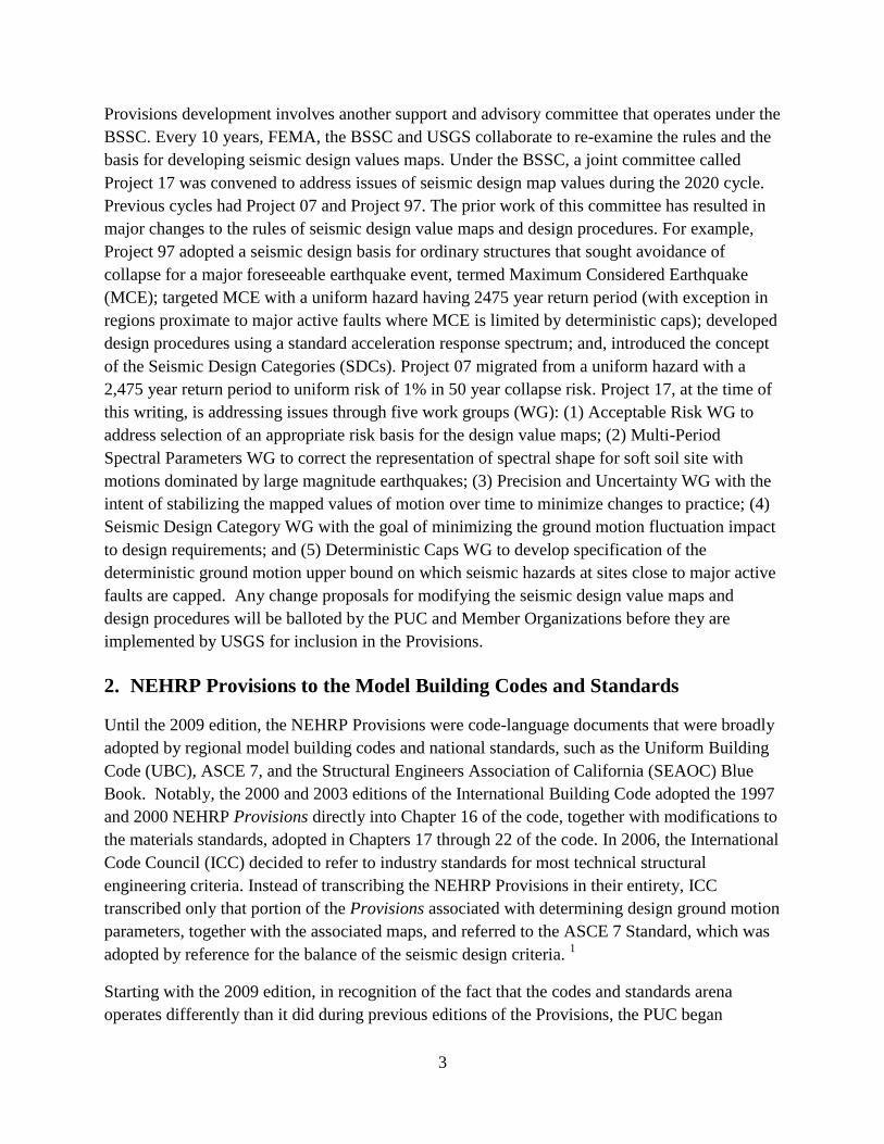
This report, prepared at the outset of the 2020 NEHRP Provisions development cycle, presents
some important background on the NEHRP Provisions development process and summarizes the
results of the first ballot in the 2020 development cycle to adopt ASCE/SEI 7-16 as the primary
reference document for the Provisions. As a practice initiated with the 2009 edition of the
Provisions, after adopting ASCE/SEI 7, the BSSC makes substantive recommendations for
modification and improvement to the standard based on recent research and improvements in
knowledge. In the 2015 NEHRP Provisions the BSSC developed significant modifications to
ASCE/SEI 7-10, which were then adopted in ASCE/SEI 7-16. For the 2020 Provisions the BSSC
has adopted ASCE/SEI 7-16 as the reference with the intent to make changes that will be
reflected in ASCE/SEI 7-22. This report also summarizes some of the important changes made by
the 2015 NEHRP Provisions that were adopted by ASCE/SEI 7-16 and a few changes that were
further modified in the ASCE/SEI 7-16.

1
1. Introduction to Development of NEHRP Provisions
In 2015, Federal Emergency Management Agency (FEMA)’s National Earthquake Hazards
Reduction Program awarded the a contract to the Building Seismic Safety Council (BSSC) of
National Institute of Building Sciences (NIBS) to develop the 2020 National Earthquake
Hazards Reduction Program (NEHRP) Recommended Seismic Provisions for New Buildings and
Other Structures (Provisions). The NEHRP Provisions is a knowledge-based state-of-the-art
seismic code resource document, which provides a platform for translation of new research
results and consensus engineering practice for use in updating national design standards and
building codes. Since the establishment of NEHRP in 1977, FEMA, as one of the four NEHRP
agencies, has contracted with BSSC, to develop and publish nine editions of NEHRP Provisions,
in 1985, 1988, 1991, 1994, 1997, 2000, 2003, 2009, and 2015 in three to five year cycles. The
2020 Provisions will mark the 10th
publication.
Authorized by the U.S. Congress, the National Institute of Building Sciences provides an
authoritative source and a unique opportunity for open and candid discussion among private and
public sectors within the built environment. BSSC provides an active national forum for all
entities interested in the seismic provisions development process. BSSC not only assembles
technically sound building seismic provisions that are vetted by hundreds of subject-matter
experts, but casts them as consensus resources that account for technical, social, economic, and
regulatory issues that affords wide acceptance and implementation by building code
organizations, states, local communities, and federal agencies. The entities that are involved with
BSSC and the Provisions development process are presented in Figure 1.
Fig. 1. Entities Involved with the Building Seismic Safety Council
BSSC
Academia Government
Products
and
Materials
Building
Owners and
Contractors
Structural
Engineers
and
Designers
Standards &
Codes
Organizations
and Building
Officials
Associations
and
Nonprofits

2
The Provisions are developed by a volunteer Provisions Update Committee (PUC) of national
subject matter experts approved by the BSSC Board of Direction. The PUC includes technical
experts representing the breadth of seismic design disciplines, the former PUC chair from the
previous cycle, and the chair of the ASCE 7 Seismic Subcommittee. Representatives from
FEMA, US Geological Survey (USGS), and National Institute of Standards and Technology
(NIST) serve as liaisons to PUC. The PUC selects relevant topics that are based on
Recommended Issues and Research Needs, a report that identified remaining issues in previous
cycle, and other inputs, such as new USGS seismic hazard models, NIST applied research and
NSF and industry sponsored research. Topics are then assigned to volunteer Issue Teams, which
include both PUC members and others with expertise in the issues being considered.
The BSSC conducts a deliberative process that allows academic, technical and detailed comment
on proposals and resolution of conflicts in seismic design guidance. As a first step, Issue Teams
prepare proposals for technical changes through consensus, which are then balloted, and in some
cases re-balloted according to a Board approved set of procedures, by the PUC, followed by an
industry ballot by the BSSC Member Organizations (MOs) representing the broader seismic
community. The BSSC Board of Direction balances and referees the MOs to ensure that
concerned commercial interests are involved in changes affecting seismic engineering. The
BSSC Board of Direction further reviews all ballots to ensure that voting procedures approved at
the outset of the cycle are observed. The organization chart of Provisions development is
demonstrated below.
Fig. 2 BSSC Structure for Developing the NEHRP Provisions
Provisions Update Committee (PUC)
(Provides consensus review, comment
resolution, and approval/disapproval of
all proposals by Issue Teams)
Federal Emergency Management Agency
(FEMA)
(Contract with the Institute for the BSSC
to develop the NEHRP Provisions)
BSSC Board of Direction
(Oversees Council activities)
Issue Teams
(Examine specific topics in need of
attention by subject matter expertise,
report to PUC)
All work are coordinated
by the BSSC Project
Managers Member
Organizations
3
Provisions development involves another support and advisory committee that operates under the
BSSC. Every 10 years, FEMA, the BSSC and USGS collaborate to re-examine the rules and the
basis for developing seismic design values maps. Under the BSSC, a joint committee called
Project 17 was convened to address issues of seismic design map values during the 2020 cycle.
Previous cycles had Project 07 and Project 97. The prior work of this committee has resulted in
major changes to the rules of seismic design value maps and design procedures. For example,
Project 97 adopted a seismic design basis for ordinary structures that sought avoidance of
collapse for a major foreseeable earthquake event, termed Maximum Considered Earthquake
(MCE); targeted MCE with a uniform hazard having 2475 year return period (with exception in
regions proximate to major active faults where MCE is limited by deterministic caps); developed
design procedures using a standard acceleration response spectrum; and, introduced the concept
of the Seismic Design Categories (SDCs). Project 07 migrated from a uniform hazard with a
2,475 year return period to uniform risk of 1% in 50 year collapse risk. Project 17, at the time of
this writing, is addressing issues through five work groups (WG): (1) Acceptable Risk WG to
address selection of an appropriate risk basis for the design value maps; (2) Multi-Period
Spectral Parameters WG to correct the representation of spectral shape for soft soil site with
motions dominated by large magnitude earthquakes; (3) Precision and Uncertainty WG with the
intent of stabilizing the mapped values of motion over time to minimize changes to practice; (4)
Seismic Design Category WG with the goal of minimizing the ground motion fluctuation impact
to design requirements; and (5) Deterministic Caps WG to develop specification of the
deterministic ground motion upper bound on which seismic hazards at sites close to major active
faults are capped. Any change proposals for modifying the seismic design value maps and
design procedures will be balloted by the PUC and Member Organizations before they are
implemented by USGS for inclusion in the Provisions.
2. NEHRP Provisions to the Model Building Codes and Standards
Until the 2009 edition, the NEHRP Provisions were code-language documents that were broadly
adopted by regional model building codes and national standards, such as the Uniform Building
Code (UBC), ASCE 7, and the Structural Engineers Association of California (SEAOC) Blue
Book. Notably, the 2000 and 2003 editions of the International Building Code adopted the 1997
and 2000 NEHRP Provisions directly into Chapter 16 of the code, together with modifications to
the materials standards, adopted in Chapters 17 through 22 of the code. In 2006, the International
Code Council (ICC) decided to refer to industry standards for most technical structural
engineering criteria. Instead of transcribing the NEHRP Provisions in their entirety, ICC
transcribed only that portion of the Provisions associated with determining design ground motion
parameters, together with the associated maps, and referred to the ASCE 7 Standard, which was
adopted by reference for the balance of the seismic design criteria. 1
Starting with the 2009 edition, in recognition of the fact that the codes and standards arena
operates differently than it did during previous editions of the Provisions, the PUC began
4
adopting the ASCE 7 Standard as the base document of the provisions by reference, and focused
on substantive technical and conceptual modification and improvement of the standard based on
recent research and improvements in knowledge. This practice has continued as shown by the
following table.
Table 1. ASCE/SEI 7 Adoptions by NEHRP Provisions
Provisions Edition Reference Standard Adopted for
Provisions Development
Standard Affected by Provisions
Development
2009 ASCE/SEI 7-05 ASCE/SEI 7-10
2015 ASCE/SEI 7-10 ASCE/SEI 7-16
2020 ASCE/SEI 7-16 ASCE/SEI 7-21
In this manner, the NEHRP Provisions became a technical resource and proving ground for new
requirements and consensus engineering practices that are offered for use by the ASCE Standard
and the International Building Code. The 2009 and 2015 NEHRP Provisions include (and the
2020 Provisions will include): Part I Provisions for recommended new changes and
modifications to the adopted ASCE/SEI 7; Part II with the full ASCE 7 commentary that
includes changes based on Part I; and, Part III for resource papers covering new concepts and
methods for trial use and other supporting materials for design professionals.
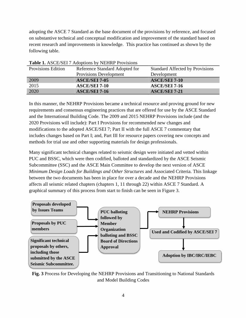
Many significant technical changes related to seismic design were initiated and vetted within
PUC and BSSC, which were then codified, balloted and standardized by the ASCE Seismic
Subcommittee (SSC) and the ASCE Main Committee to develop the next version of ASCE
Minimum Design Loads for Buildings and Other Structures and Associated Criteria. This linkage
between the two documents has been in place for over a decade and the NEHRP Provisions
affects all seismic related chapters (chapters 1, 11 through 22) within ASCE 7 Standard. A
graphical summary of this process from start to finish can be seen in Figure 3.
Fig. 3 Process for Developing the NEHRP Provisions and Transitioning to National Standards
and Model Building Codes
Proposals by PUC
members
Proposals developed
by Issues Teams
Significant technical
proposals by others,
including those
submitted by the ASCE
Seismic Subcommittee.
NEHRP Provisions PUC balloting
followed by
Member
Organization
balloting and BSSC
Board of Directions
Approval
Used and Codified by ASCE/SEI 7
Adoption by IBC/IRC/IEBC

5
3. Adoption of ASCE/SEI 7-16 for Developing the 2020 NEHRP Provisions
3.1 General Balloting Procedure
As mentioned above, BSSC adopted ASCE/SEI 7-16 standard as the reference for developing the
2020 NEHRP Provisions for consideration to be adopted in next edition of ASCE/SEI 7
standard. This adoption was accomplished as the first ballot for development of the 2020
NEHRP Provisions in a two- step process, first a ballot by PUC members, then a ballot by the
member organizations of BSSC. The BSSC staff conducted the ballots using the newly
developed online balloting process that incorporates the BSSC Board of Direction accepted
procedures:
Electronic ballots shall provide four alternatives “Yes,” “Yes with Reservations,” “No,”
and “Not Voting.” “Yes with Reservations” and “No” votes must be accompanied by an
explanation for the vote. A “No” vote must be accompanied by specific suggestions to
convert the negative to affirmative. If no comments are provided when required, the vote
on that ballot item will not be tallied.
On an electronic ballot, a two thirds (2/3) affirmative (“Yes” and “Yes with
Reservations”) vote of the “Yes,” “Yes with Reservations,” and “No” votes received shall
be sufficient to record a favorable vote provided at least one half (1/2) of the eligible
committee members ballots . . . are returned. If a 50 percent response is not obtained by
the closing date, the ballot period may be extended at the discretion of the PUC Chair,
and all those eligible to vote will be notified of such an extension.
The PUC met to resolve comments within the ballot according the general procedures which are:
Following balloting, each comment received on each proposal shall be classified as one
of the following:
a. Persuasive (relevant and of such substance as to require incorporation into the
proposal),
b. Nonpersuasive,
c. Nonresponsive (not consistent with the intent or subject matter of the proposal), or
d. Editorial/Persuasive (editorial in nature and revisions to be made).
Each proposal proponent or IT shall categorize the ballot comments received on the
proposal as indicated above and shall present the categorization to the PUC with
recommendations as follows:
a. For comments categorized as “Persuasive,” the proposal proponent or IT may
recommend to the PUC either that the proposal be substantively revised to respond to
the comment and subsequently reballoted or that the issues raised by the comment
require further study during the next update.

6
b. For comments categorized as “Nonpersuasive” or “Nonresponsive,” the proposal
proponent or IT will explain the reasoning behind that decision.
c. For comments categorized as “Editorial,” the proposal proponent or IT will identify
the specific changes to be made.
d. Substantive technical changes that are conceptually simple may be approved based on
a vote of the PUC. Revisions that are complex shall be re-balloted.
The PUC shall vote on each recommended resolution of each “No” (Negative) vote in
accordance with the procedures above. All Negatives must be resolved through PUC
vote for the proposal to be passed by the PUC. A PUC vote is not required for resolution
of comments made in a “Yes with Reservations” vote except where the comment
suggests a substantive technical change to the proposal.
If a proposal fails an electronic ballot, it shall not be reconsidered at a PUC meeting
without significant revision and a second PUC electronic ballot, unless the PUC votes to
proceed with resolution of comments. At a proponent’s request and at the Chair’s
discretion, a failed proposal may be discussed for the purpose of providing guidance to
the proponent for potential resubmittal.
Then the BSSC Board of Direction will meet to determine that the procedures were appropriately
followed and to accept the ballot conducted by the PUC to go for MO balloting. The ballot items
accepted by MOs, resolved by the PUC necessary, and approved by BSSC Board will be
included in the 2020 NEHRP Provisions.
The PUC and MO first ballots are described in the next two sections.
3.2 Provisions Update Committee (PUC) Ballot
The adoption of ASCE/SEI 7-16 as the basis for 2020 NEHRP Provisions is conducted that
ASCE 7-16 is adopted by its entirety rather than chapter by chapter. This allows any major
differences between the 2015 Provisions and ASCE 7-16 that PUC wants to retain or further
improve to be considered as separate new proposals.
Ballot No. 1: Adoption of ASCE 7-16 as the basis for 2020 NEHRP Provisions
Scope: Review the seismic requirements of ASCE/SEI 7-16 and adopt ASCE/SEI 7-16 as the
primary reference standard, with exceptions and modifications, for the 2020 edition of the
Provisions.
PUC Online Voting:
Period: July 14, 2017-August 5, 2017
Results: as shown in Table 2 from the Institute online balloting process, sixteen members
voted with 14 voting yes and 2 voting yes with reservations. The two “yes with
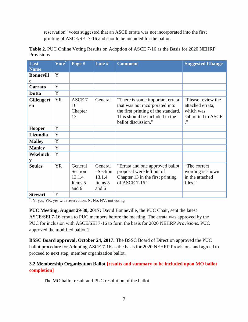
7
reservation” votes suggested that an ASCE errata was not incorporated into the first
printing of ASCE/SEI 7-16 and should be included for the ballot.
Table 2. PUC Online Voting Results on Adoption of ASCE 7-16 as the Basis for 2020 NEHRP
Provisions
*: Y: yes; YR: yes with reservation; N: No; NV: not voting
PUC Meeting, August 29-30, 2017: David Bonneville, the PUC Chair, sent the latest
ASCE/SEI 7-16 errata to PUC members before the meeting. The errata was approved by the
PUC for inclusion with ASCE/SEI 7-16 to form the basis for 2020 NEHRP Provisions. PUC
approved the modified ballot 1.
BSSC Board approval, October 24, 2017: The BSSC Board of Direction approved the PUC
ballot procedure for Adopting ASCE 7-16 as the basis for 2020 NEHRP Provisions and agreed to
proceed to next step, member organization ballot.
3.2 Membership Organization Ballot [results and summary to be included upon MO ballot
completion]
- The MO ballot result and PUC resolution of the ballot
Last
Name
Vote* Page # Line # Comment Suggested Change
Bonnevill
e
Y
Carrato Y
Dutta Y
Gillengert
en
YR ASCE 7-
16
Chapter
13
General “There is some important errata
that was not incorporated into
the first printing of the standard.
This should be included in the
ballot discussion.”
“Please review the
attached errata,
which was
submitted to ASCE
.”
Hooper Y
Lizundia Y
Malley Y
Manley Y
Pekelnick
y
Y
Soules YR General –
Section
13.1.4
Items 5
and 6
General
–Section
13.1.4
Items 5
and 6
“Errata and one approved ballot
proposal were left out of
Chapter 13 in the first printing
of ASCE 7-16.”
“The correct
wording is shown
in the attached
files.”
Stewart Y

8
- BSSC Board of Direction acceptance of the MO ballot, as resolved as necessary by the
PUC, for serving as the reference document for the 2020 NEHRP Provisions

9
4. Major Differences between 2015 NEHRP Provisions and ASCE/SEI 7-16
The 2015 NEHRP Provisions were developed from 47 proposals submitted, reviewed, and
balloted between March 2011 and February 2015. The 2015 NEHRP Provisions recommended
many changes to chapters 11 through 22 of ASCE/SEI 7-10: 2
Revisions, replacements and additions to Chapters 11, 12, 14, 15, 21 and 22.
Complete replacement of Chapters 16, 17, 18 and 19.
A minor modification to Chapter 1.
The addition of Chapter 24.
For information on specific changes in Part 1 of the Provisions, Table 3 below provides the
topics of the approved change proposals along with their relevant section numbers and
commentary section numbers of ASCE/SEI 7-10.
Except for Chapter 24, which was not accepted by the ASCE Seismic Subcommittee for
inclusion in ASCE 7-16, most of the changes proposed by the 2015 NEHRP Provisions were
accepted and used in ASCE/SEI 7-16, which was then adopted by reference by the International
Building Codes (IBC) 2018. Some of the changes were modified for code language by Seismic
Subcommittee (SSC) of ASCE 7. Important changes in Chapters 11, 12, 16, 19, and 21 are
summarized in this section based on presentations made at the August 29-30, 2017 PUC meeting
by the proposal proponents from the 2015 cycle. The presentations are included in the Appendix.
Table 3. 2015 NEHRP Provisions Change Proposals and Their Relevant Section Numbers and
Commentary Section Numbers of ASCE/SEI 7-10 Topics of change proposals Related or new sections of ASCE/SEI 7 Related commentary sections
Intent of the Provisions Section 1.1 (this applies to the
2015 Provisions only) 2.1
Adoption of ASCE/SEI 7-10 Chapters 11-23, Supplement No. 1 and the Expanded Commentary for the 2015 Provisions
All sections of Chapters 11-23
in ASCE/SEI 7-10 without
exception
All sections of C11-C22
Revised site coefficients Fa, Fv, and FPGA for MCER spectral response and maximum considered geo-mean peak ground acceleration PGAM
Sections 11.4.2, 11.4.3, and 11.8.3
C11.4, C11.4.2, C11.4.3 C11.8
Site-specific ground motion procedures for certain structures on site classes D and E
Sections 11.4.7, and 21.4 C11.4.7 C21.4
Limit SMS not less than SM1 Section 11.4.3 C11.4.3
Adoption of FEMA P-695 methodology for qualification of alternative new
seismic resistant systems Section 12.2.1, 12.2.1.1 C12.2.1.1
Adoption of FEMA P-795 methodology for equivalence of substitute
components Section 12.2.1.2 C12.2.1.2
Strength-based design of foundations Sections 1.2,12.1.5, 12.7, and
12.13.1-7 C12.13.1, 5-7
Requirements for using maximum Ss value in determination of Cs Sections 12.8.1.3 C12.8.1.3

10
Topics of change proposals Related or new sections of ASCE/SEI 7 Related commentary sections
Accidental Torsion Section 12.8.4.2 C12.8.4.2
Modal analysis procedure in scaling design values of combined response, 3D structural modeling and linear modal response history analysis
Section 12.9.1
Section 12.9.4 Section 12.9.8
Section 12.9.2
C12.9.1
C12.9.3 C12.9.4
C12.9.8 C12.9.2
Requirements for structure foundations on liquefiable sites Section 12.13.8 C12.13.8
Revision to section 12.14 Simplified Alternative Seismic Design Criteria Section 12.14.1 C12.14.1
A new alternative diaphragm design procedure and diaphragm design force
reduction factor Rs
Sections 11.2, 11.3, 12.3.1.3,
12.10, and 12.10.3
C11.2, C11.3,
C12.3.1.3, C12.10, and C12.10.3
Diaphragm design procedure mandatory for pre-cast concrete diaphragm in
SDC D, E and F, optional for other concrete and wood sheathing diaphragms
Sections 11.3, 14.2.2.1, and
14.2.4, C14.2.2.1, C14.2.4
Adoption of ASCE/SEI 7-10 Supplement No. 2, deletion of the line item on tanks and vessels supported on other structures or towers in Table 15.4
Section 15.4.1 C15.4.1
Chapter 16 Seismic Response History Procedure
Sections All listed sections of
Chapter 16, 11.4.7, and
12.4.2.2
C16, C11.4.7
Chapter 17 Seismic Design Requirements for Seismically Isolated
Structures
All listed sections of Chapter
17 C17
Steel ordinary concentrically braced frames (OCBF) used in isolated
structures in SDC D, E and F Section 17.2.5.4 C17.2.5.4
Steel grid frames at base level of isolated structures Section 17.2.4.9
Chapter 18 Seismic Design Requirements for Structures with Damping
Systems
All listed sections of Chapter
18 C18
Chapter 19 Soil-Structure Interaction for Seismic Design All listed sections of Chapter
19 C19
Seismic design ground motion maps for Guam and America Samoa Chapter 22 Introduction and Figures 22-7, 22-8 and 22-13
Seismic design ground motion maps based-on the 2014 USGS seismic hazard maps
Chapter 22 Figures 22-1, 22-2, 22-9, 22-18, 22-19
C22
Chapter 23, Vertical Ground Motions for Seismic Design (retained from 2009 NEHRP Provisions)
All sections of Chapter 23A C23A
New Chapter 24 Alternative Seismic Design Requirements for SDC B
Buildings All sections of new Chapter 24 All sections of C24
4.1 Major Differences in Ground Motion, Site Specific Procedure
Design ground motion is one of the primary factors used to determine the required seismic
resistance (strength) of structures and supported nonstructural components. Design ground
motion is defined by an acceleration response spectrum and characterized by the following
parameters:

11
SDS = 2/3 × Fa × Ss
SD1 = 2/3 × Fv × S1
Where SDS and SD1 are the design earthquake spectral response acceleration parameters at short
period and at 1-second period, respectively. Ss and S1 are the USGS mapped values of MCER
spectra accelerations for reference soil conditions. Fa and Fv are coefficients related to Site Class
that indicate, respectively, the relative amplification or attenuation effects of site soils on short-
period and long-period ground shaking energy.
The 2015 NEHRP Provisions contain updated values for the Fa and Fv coefficients (Tables 11.4-
1 and 11.4-2). These coefficients were originally developed in the 1990s based primarily on
recorded motions from the 1989 Loma Prieta Earthquake. Studies at the Pacific Earthquake
Engineering Research Center considered shaking data from more recent earthquakes and
combined this information with models of site nonlinearity to derive new coefficients. In
general, the values for Fa and Fv are now somewhere between 80% and 120% of their previously
tabulated values. 3
ASCE/SEI 7-16 adopted the new site coefficient values in the 2015 NEHRP
Provisions, with the exception that for Site Class E when S1 is equal to or greater than 0.2 s,
ASCE/SEI 7-16 refers to site specific analysis instead of providing values (see Table 4). At the
time of this writing, the ASCE 7 Seismic Subcommittee is considering providing these values as
found in the 2015 NEHRP Provisions in a supplement of ASCE/SEI 7-16.
Table 4. Long-Period Site Coefficient, Fv, 2015 NEHRP Provisions and ASCE/SEI 7-16 Mapped Risk-Targeted Maximum Considered Earthquake ( RMCE ) Spectral Response
Acceleration Parameter at 1-s Period
Site
Class 1 0.1S
1 0.2S 1 0.3S
1 0.4S 1 0.5S
1 0.6S
A 0.8 0.8 0.8 0.8 0.8 0.8
B 0.8 0.8 0.8 0.8 0.8 0.8
C 1.5 1.5 1.5 1.5 1.5 1.4
D 2.4 2.21 2.0
1 1.9
1 1.8
1 1.7
1
E 4.2 3.31
(ASCE 7-
16: See
Section 11.4.8)
2.81
(ASCE 7-
16: See
Section 11.4.8)
2.41
(ASCE 7-
16: See
Section 11.4.8)
2.21
(ASCE 7-
16: See
Section 11.4.8)
2.01
(ASCE 7-
16: See
Section 11.4.8)
F See
Section 11.4.8
See
Section 11.4.8
See
Section 11.4.8
See
Section 11.4.8
See
Section 11.4.8
See
Section 11.4.8
Note: 1 Also, see requirements for site-specific ground motions in Section 11.4.8.
In seismic design, the three-domain design spectrum (constant response acceleration, velocity
and displacement) is used to define ELF (Equivalent Lateral Force Procedure) (and MRSA -
Modal Response Spectrum Procedure) design forces. The three-domain design spectrum is
derived from three seismic design maps values: the short period and 1-second period spectral
values, SS and S1; and the constant displacement transition period, TL. Late in the 2015 NEHRP
Provisions update cycle, it was found that the traditional three-domain design derived from these

12
parameters did not adequately address ground motion demands for sites on soft soils that are
dominated by large magnitude events. For such sites, it was found that the spectral demands
could be significantly underestimated at periods greater than 1-second, and could be
overestimated at short periods.3,5
Ideally, for such sites, the design spectral shape would be
defined by a multi-period spectrum covering a full range of periods. However, due to time
constraints, it was not possible to implement such a revision in the last cycle. The 2015
Provisions adopted the new site-specific requirements of Section 11.4.7 in lieu of a more
comprehensive approach to add new “spectrum shape adjustment” factors, Ca and Cv, to the
equations of Section 11.4 that would define values of SMS and SM1. More details can be found in
the paper written by Kircher5. The new site-specific analysis requirements of Section 11.4.7
necessitated changes to the site-specific analysis methods of Chapter 21. While the 2015 NEHRP
Provisions included changes in the Section 21.4 requirements for determining values of SDS and
SD1 from a site-specific design spectrum, but the Provisions missed the changes under section
21.2.2 requirements defining the deterministic lower limit on the MCER response spectrum, and
Section 21.3 requirements establishing the 80 percent lower-bound limit on site-specific design
spectrum. ASCE/SEI 7-16 included the changes in Section 21.4 proposed in the 2015 NEHRP
Provisions, and picked up the last-minute changes under Sections 21.2.2 and 21.3.
In the 2020 Provisions cycle, the multi-period spectrum issue is being addressed through Project
17.
4.2 Major Differences in Diaphragm Design
Diaphragms are generally treated as horizontal deep beams or trusses that distribute lateral forces
to the vertical elements of a seismic force-resisting system. As deep beams, diaphragms must be
designed to resist the resultant shear and bending stresses. Diaphragms are commonly compared
to girders, with the roof or floor deck analogous to the girder web in resisting shear, and the
boundary elements (chords) analogous to the flanges of the girder in resisting flexural tension
and compression. As in girder design, the chord members (flanges) must be sufficiently
connected to the body of the diaphragm (web) to prevent separation and to force the diaphragm
to work as a single unit.2 The diaphragm provisions in ASCE/SEI 7-10 (and previous editions)
take an elastic design approach for diaphragm elements, basing the forces on a multiple of the
floor force calculated using the Equivalent Lateral Force (ELF) procedure. This has historically
resulted in generally acceptable seismic diaphragm performance for most building configurations
and diaphragm material types. However, during the 2015 cycle, studies had shown that the
actual force levels imposed on diaphragms during ground shaking could be significantly higher
than those currently prescribed in the code, particularly when diaphragm response is near-elastic.
The effects of higher modes than the first mode were found to contribute significantly to
diaphragm response, and these findings prompted an investigation into the entire process of
diaphragm design.3

13
Based on experimental and analytical data and observations of building performance in past
earthquakes, the 2015 Provisions contained new equations that generally yield larger design
forces in diaphragm design. Since diaphragms designed with the current procedure are generally
well-behaving, though, the capacity side of diaphragm design was also addressed, which is
related to material-specific factors that are related to overstrength and deformation capacity. In
short, demands were previously underestimated but were also assessed against unrealistically
limited elastic capacities. The new procedure, despite its higher calculated demands, yields a
similar final design because of the additional consideration of diaphragm ductility. It should be
noted that for diaphragms constructed of most materials (wood sheathing, metal deck, etc.), the
2015 NEHRP provisions only provide an improved understanding of seismic diaphragm
behavior, but the new procedure is more critical for precast concrete diaphragms. Tests show
that, compared to other systems, precast concrete diaphragms have limited ductility; more
specifically, the long diaphragm spans that precast diaphragms lend themselves to cause
relatively low performance of the system. In essence, the new diaphragm design procedure in
the 2015 NEHRP Provisions, which was adopted by ASCE/SEI 7-16 in Section 12.10.3, is being
mandated for precast concrete diaphragms in buildings assigned to SDC (Seismic Design
Category) C, D, E, or F and are being offered as an alternative to Sections 12.10.1 and 12.10.2
for other precast concrete diaphragms, cast-in-place concrete diaphragms, and wood-sheathed
diaphragms supported by wood framing. 2,3,4
It should be noted that alternative diaphragm design for steel deck diaphragms, for which it is
believed that more research is needed and is currently one of the topics under the 2020 NEHRP
Provisions cycle, is included as a Part 3 resource paper in 2015 NEHRP Provisions and is not
included in ASCE/SEI 7-16. Some other minor adjustments of the design parameters are made in
ASCE/SEI 7-16, such as for seismic force for diaphragms, including chords, collectors, and their
connections to vertical elements.
In the 2015 NEHRP Provisions, Cp0 is constant up to 80% height of the building, while in
ASCE/SEI 7-16, where Cp0 is not constant up to 80% height of the building, parameter Cpi is
used. And while there is no lower-bound limit on Cpn in the 2015 NEHRP Provisions, ASCE/SEI
7-16 has a lower bound limit of Cpi.
4.3 Major Differences in Non-Linear Response Analysis
Response history analysis (RHA) is a form of dynamic analysis in which the response of a
structure to a suite of ground motions is evaluated through numerical integration of the equations
of motions. In nonlinear response history analysis, the structure’s stiffness matrix is modified
throughout the analysis to account for the changes in element stiffness associated with hysteretic
behavior and P-delta effects. When nonlinear response history analysis is performed, the R , dC ,
and 0Ω coefficients considered in linear procedures are not applied because the nonlinear
analysis directly accounts for the effects represented by these coefficients.2

14
Nonlinear response history analysis is permitted to be performed as part of the design of any
structure and is specifically required to be performed for the design of certain structures
incorporating seismic base isolation or energy dissipation systems. Nonlinear response history
analysis is also frequently used for the design of structures that use alternative structural systems,
or do not fully comply with the prescriptive requirements of the standard in one or more ways.2
Before this edition, ASCE 7 specified that nonlinear response history analyses be performed
using ground motions scaled to the design earthquake level, and that design acceptance checks
be performed to ensure that mean element actions do not exceed two-thirds of the deformations
at which loss of gravity-load-carrying capacity would occur.2
The PUC judged that these
requirements lacked specificity in many areas, leading to inconsistencies in interpretation. In
2015 NEHRP Provisions, a complete reformulation of these requirements was undertaken to
require analysis at the Risk-Targeted Maximum Considered Earthquake ( RMCE ) level, and to
be more consistent with the target reliabilities indicated in Section 1.3.1.3.3
The procedure in the 2015 NEHRP Provisions is intended to provide buildings with equivalent or
better seismic performance compared to designs using the ASCE Chapter 12 procedures. It
includes a code-level evaluation of the building using either the Equivalent Lateral Force (ELF)
Procedure or the Modal Response Spectrum Analysis (MRSA) Procedure for the purpose of
assuring that the structure designed using the RHA provisions will be equivalent in terms of
strength (though not necessarily displacement). The nonlinear analysis is then performed to
demonstrate that the structure has predictable and stable response under MCER level ground
shaking and to determine forces for force-controlled components. Service-level evaluation (to
address for example Risk Category IV buildings) is not required because ground motion for such
analysis is not provided by Chapters 11 and 12.2.3
Prior to the 2015 NEHRP Provisions, ASCE 7 specified that nonlinear response history analyses
be performed using ground motions scaled to the design earthquake level. In the 2015 NEHRP
Provisions, the level of ground motion is defined by target response spectra that might be derived
from either the MCER spectrum determined in accordance with Chapter 11 or Chapter 21, which
conservatively envelopes the results of seismic hazard analysis for each period, or a Conditional
Mean Spectrum, in which the spectrum is calculated based on a spectral acceleration at an
appropriate period and the mean of spectral acceleration values at other periods. This
conditional calculation ensures that the resulting spectrum is reasonably likely to occur and that
ground motions selected to match the spectrum have an appropriate spectral shape consistent
with naturally occurring ground motions at the site of interest. The procedure requires eleven
ground motions (versus minimum of three ground motions in ASCE/SEI 7-10) representing near-
field (if appropriate) and far field sites. The procedure specifies the lower bound (0.2T) and
upper bound (generally 2.0T) period range for ground motions to be scaled to so that they are
representative of the site specific MCER spectrum. 2.3

15
Modeling requirements in the 2015 NEHRP Provisions are given with the intent of reasonably
capturing the spatial and temporal distributions of inelasticity. Three-dimensional analysis is
required for the final analysis and requirements are specified for realistically addressing gravity
loading, P-delta effects and diaphragm modeling to cover the range of expected stiffness.
Inherent torsion is addressed through the modeling requirements in a manner similar to that
given in Chapter 12 and accidental torsion is not required to be explicitly modeled (a rigorously
debated issue), though the commentary provides recommendations for addressing buildings
likely to perform in a highly torsional manner. 2.3
Acceptance criteria are expressed in terms of global response in which unacceptable performance
is defined based on possible collapse, story drift, non-convergence, deformation-controlled
response and force-based demands for brittle components; and, element-level response,
considering both deformation and force-controlled actions. A big focus of the chapter in the 2015
NEHRP Provisions is to develop acceptance criteria more clearly tied to risk targeted goals as
those used in Chapter 12.2.3
Design review is required for all structures designed in accordance with the RHA procedure.
The review is required to be performed by one or more professionals with expertise in ground
motion selection and scaling, analytical modeling and structural system behavior. 2.3
While ASCE/SEI 7-16 adopted almost all changes and made some language more specific and
more standard-like, there is one major difference under Section 16. 3 Modeling and Analysis for
Torsion: the 2015 Provisions leave this to the linear design step, but the ASCE/SEI 7-16 allows
linear design step if no Type 1a/1b irregularity exists, otherwise requiring mass offsets in the
non-linear model. Some other minor tweaks by ASCE/SEI 7-16 include: for near-fault verse far-
field ground motions (under section 16.2), the Provisions left this fairly non-prescriptive while
ASCE/SEI 7-16 added specificity in Chapter 11 (near-fault is R < 15km if M > 7.0 and R <
10km if 7.0 > M > 6.5); for orientation of ground motions in far-field, the Provisions applied
pairs of records with “random orientation”, while ASCE/SEI 7-16 added a more specific +/- 10%
requirement (Section 16.2.4, “each pair of horizontal ground motion components shall be applied
to the building at orthogonal orientations such that the average (or mean) of the component
response spectrum for the records applied in each direction is within +/- 10% of the mean of the
component response spectra of all records applied for the period range specified in Section
16.2.3.1).
4.4 Soil Structure Interaction
In an earthquake, the shaking is transmitted up through the structure from the geologic media
underlying and surrounding the foundation. The response of a structure to earthquake shaking is
affected by interactions among three linked systems: the structure, the foundation, and the
geologic media underlying and surrounding the foundation. In a seismic analysis, it is typically
assumed that structures have a fix base at the foundation-soil interface and the forces that are
16
applied to the structure are devised based on parameters representing free-field ground motions.
The term “free-field” refers to motions not affected by structural vibrations or the foundation
characteristics of the specific structure. The Soil Structure Interaction (SSI) provisions are
intended to allow a more complete and accurate analysis of the combined system including
structure, foundation and underlying soil/rock2.
The 2015 NEHRP Provisions provide a complete revision to the ASCE 7-10 Chapter 19 SSI
requirements, and allow the designer to account for foundation deformations, inertial effects and
kinematic effects. Substantial revisions have been made to Chapter 19 in ASCE 7-16. They
include (1) the introduction of formulas for the stiffness and damping of rectangular foundations,
(2) revisions to the formulas for the reduction of base shear caused by SSI, (3) reformulation of
the effective damping ratio of the SSI system, (4) introduction of an effective period lengthening
ratio, which appears in the formula for the effective damping ratio of the SSI system, and which
depends on the expected structural ductility demand, and, (5) the introduction of kinematic SSI
provisions. Most of these revisions are based on the NIST GCR 12-917-21 (NIST 2012) report of
a recent NEHRP research project at Applied Technology Council (ATC) on SSI.
ASCE/SEI 7-16 adopted Chapter 19 of the 2015 NEHRP Provisions with one change: The
Provisions permitted more aggressive reductions in kinematic soil structure interaction if SSI
analysis is peer reviewed, and ASCE/SEI 7-16 did not allow the peer-review-based reduction.
4.5 Summary of other differences
In recent years, engineers and building officials have become concerned that the seismic design
requirements for Seismic Design Category (SDC) B are complex and are difficult to implement.
The 2015 NEHRP Provisions contain a new chapter, Chapter 24, that is a simplified, alternate
seismic design procedure for structures in Seismic Design Category (SDC) B. A structure in
SDC B designed using 2015 Provisions Chapter 24 is essentially equivalent to a design using
ASCE 7-10 Chapter 12, but the engineer has the convenience of a much simpler, more
transparent, and easy to follow design requirement document to work with. For example,
Chapter 24 does not contain the “special” lateral force resisting systems, removes TL from the
calculation for the base shear coefficient, and only contains Chapter 13 requirements for parapet
and hazardous materials provisions.3
While Chapter 24 will produce the same design as following other chapters in ASCE/SEI 7-10,
with concerns that this will further increase the already large volume size of ASCE/SEI 7, it was
not included in the ASCE/SEI 7-16. Chapter 24 was subsequently updated to be compatible with
the latest ASCE/SEI 7-16 and is published as a standalone FEMA NEHRP technical resource
document (FEMA P-1091).

17
5. Concluding Remarks
This report, prepared during the 2020 NEHRP Provisions development cycle, presents some
important background on the NEHRP Provisions development process and summarizes the
results of the first ballot in the 2020 development cycle to adopt ASCE/SEI 7-16 as the primary
reference document for the Provisions. Parallel to the PUC, Member Organizations, and BSSC
Board of Direction approving the adoption of ASCE/SEI 7-16 for the 2020 cycle, the PUC has
been and will be working a wide range of topics that will result in proposals to improve the
current ASCE/SEI 7-16 standard. The topics being considered include (1) seismic performance
objective evaluation; (2) seismic force resisting systems and design coefficients; (3) modification
of existing modal response spectrum method; (4) shear wall design; (5) nonstructural
components; (6) nonbuilding structures; (7) soil-foundation interaction; (8) base isolation and
energy dissipation; (9) diaphragm issues – RWFD (rigid wall flexible diaphragms) and
alternative diaphragm design provisions; (10) and seismic design value map related topics and
design procedures, which will be initiated from Project 17.
With the NEHRP Provisions as its basis, BSSC has also engaged in a series of outreach efforts to
educate the engineers, the disaster community, and the general public, which include live
webinars, online training courses, workshops, special BSSC sessions at national conventions,
and conference papers and presentations.
The NEHRP Provisions have successfully advanced the seismic design and analysis in the
building industry and enhanced public safety against earthquake disasters in the past 40 years.
The success of the NEHRP Provisions is due to the continuous support from the National
Earthquake Hazards Reduction Program and its four designated agencies (NIST, USGS, NSF
and FEMA), especially the Federal Emergency Management Agency (FEMA). More
importantly, thanks to the engagement and effort from numerous subject-matter experts under
the Provisions Update Committee, Project 17 Committee, organizational members, and many
other support committees under BSSC. The list of experts involved in the present cycle, the
latest development on the above mentioned topics, and new training and outreach efforts by
BSSC can be found on the BSSC website: http://www.nibs.org/?page=bssc.

18
6. References
(1) Building Seismic Safety Council (BSSC), 2017. Proceeding of Project 17 Workshop on
Seismic Hazard Mapping, Washington, DC. http://c.ymcdn.com/sites/www.nibs.org/resource/resmgr/bssc2/20170411P17WorkshopProceedin.pdf,
(2) Building Seismic Safety Council (BSSC), 2015. NEHRP Recommended Seismic Provisions
for New Buildings and Other Structures, (FEMA P-1050), prepared for the Federal
Emergency Management Agency, Washington, DC
(3) Bonneville, D. and Shuck A, 2014. An Introduction to the 2015 NEHRP Recommended
Seismic Provisions for New Buildings and Other Structures, Proceedings, 10th
U.S. National
Conference on Earthquake Engineering, Anchorage, Alaska.
(4) American Society of Civil Engineers (ASCE), 2016, Minimum Design Loads for Buildings
and Other Structures, (ASCE/SEI 7-16), ASCE, Reston, Virginia.
(5) Kircher, C. New Site-Specific Ground Motion Requirements of ASCE 7-16, Proceedings,
2017 SEAOC Convention, San Diego, CA

19
7. Appendix – Presentations on Major Differences between ASCE/SEI 7-16
and the 2015 NEHRP Provisions

2015 Provisions – ASCE/SEI 7-16 Comparisons:
Chapter 12 Diaphragms
S. K. Ghosh
S. K. Ghosh Associates LLC
Palatine, IL and Aliso Viejo, CA

Alternative ASCE 7-16 Force Level for Seismic Design of Diaphragms

Diaphragms, Chords, and Collectors
12.10.1.1 Diaphragm Design Forces. Floor and roof diaphragms shall be designed to resist design seismic forces from the structural analysis, but not less than the following forces:
Where
Fpx = the diaphragm design force
Fi = the design force applied to
Level i
wi = the weight tributary to Level i
wpx = the weight tributary to the
diaphragm at Level x

Diaphragms, Chords, and Collectors

Diaphragm Design Forces
0
1
2
3
4
5
6
7
0 20 40 60 80 100 120 140 160 180
Fpx
Fx
Force (kips)
Flo
or
Le
ve
l

Diaphragm IT Products
Design Force Level Proposal for Part 1 of the 2015 NEHRP Provisions – modifies ASCE 7-10 Section 12.10 Included in ASCE 7-16
Design Force Level Proposal for Part 3 of the 2015 NEHRP Provisions – modifies ASCE 7-10 Section 12.10
Precast Diaphragm Design Proposal for Part 1 of the 2015 NEHRP Provisions – modifies ASCE 7-10 Section 14.2 Included in ASCE 7-16
Resource Paper for Part 3 of the 2015 NEHRP Provisions

2015 NEHRP Provisions

Diaphragm Design In 2001 Rodriguez et al. noted that inelastic response in multi-story buildings tended to cause an important reduction in floor accelerations contributed by the first mode of response but had a much lesser effect on those contributed by the higher modes of response. They proposed the First Mode Reduced method, in which the roof acceleration could be determined by a square root sum of the squares combination in which the first mode contribution was reduced for inelasticity and the higher modes were left unreduced.

Diaphragm Design
Fpx = Cpxwpx/Rs
≥ 0.2SDS Ie wpx
Cpx comes from Cp0, Cpi, and Cpn
Note: Cpi is not used in the 2015 NEHRP Provisions

Diaphragm Design
2015 NEHRP
Provisions

Diaphragm Design
ASCE 7-16

Diaphragm Design
Cp0 = 0.4 SDS Ie
Cpn= m10CS2 + m2CS2
2 ≥ Cpi
Note: The lower-bound limit on Cpn is in ASCE 7-
16 only, not in the 2015 NEHRP Provisions.

Diaphragm Design
• m1 = 1 + 0.5zS (1 – 1/N)
• m2 = 0.9zS (1 – 1/N) 2
where zS = modal contribution coefficient modifier dependent on seismic force-resisting system.

Diaphragm Design
Values of mode shape factor zs
• 0.3 for buildings designed with Buckling Restrained Braced Frame systems
• 0.7 for buildings designed with Moment-Resisting Frame systems
• 0.85 for buildings designed with Dual Systems with Special or Intermediate Moment Frames capable of resisting at least 25% of the prescribed seismic forces
• 1.0 for buildings designed with all other seismic force-resisting systems

Diaphragm Design
Cpi is the greater of values given by:
Cpi = Cp0
Cpi = 0.9 m10CS

Diaphragm Design
CS = V/W or Vt/W
CS2 = minimum of:
(0.15N + 0.25) Ie SDS
Ie SDS
Ie SD1/[0.03(N -1)] for N ≥ 2 or 0 for N = 1

Consistent Look into the Design Spectra CsR
For the “Second mode”, R = 1
CS(T2) = min(0.15N+0.25, 1)IeSDS
≤ IeSD1/ [0.03(N-1)]
N: number of levels above ground,
N ≥ 2

Diaphragm Capacity
Why are we not seeing inadequate performance of diaphragms in seismic events?
Diaphragm design force reduction factor, Rs, To account for ductility and overstrength in the Diaphragm.

Diaphragm Design
Flexure-controlled diaphragm: Diaphragm with a well-defined flexural yielding mechanism, which limits the force that develops in the diaphragm. The factored shear resistance shall be greater than the shear corresponding to flexural yielding.

Diaphragm Design
Shear-controlled diaphragm: Diaphragm that does not meet the requirements of a flexure-controlled diaphragm.

Diaphragm Design (NEHRP Provisions – Part 1)
Diaphragm System Shear-
Controlled Flexure-
Controlled
Cast-in-place concrete designed in accordance with ACI 318
1.5 2
Precast concrete designed in accordance with Section 14.2.4 and ACI 318, EDO
0.7 0.7
Precast concrete designed in accordance with Section 14.2.4 and ACI 318, BDO
1.0
1.0
Precast concrete designed in accordance with Section 14.2.4 and ACI 318, RDO
1.4 1.4
Wood sheathed designed in accordance with AF&PA (now AWC) Special Design Provisions for Wind and Seismic
3.0 NA
Diaphragm Design Force Reduction Factor, Rs

Diaphragm Design (NEHRP Provisions – Part 3)
Diaphragm System Shear-
Controlled
Flexure-Controlled
Untopped steel deck designed in accordance with AISI S100 or SDI RD
- 2.0 NA
Topped steel deck designed in accordance with AISI S100 or SDI C and SDI NC
Reinforced topped steel deck with shear stud connection to framing
2.0 2.5
Other topped steel deck with structural concrete fill
1.5 2.0
Wood sheathed designed in accordance with AISI S213
- 2.0 NA
Diaphragm Design Force Reduction Factor, Rs

Diaphragm Design (ASCE 7-16)
Diaphragm System Shear-
Controlled
Flexure-Controlled
Cast-in-place concrete designed in accordance with Section 14.2 and ACI 318
- 1.5 2
Precast concrete designed in accordance with Section 14.2.4 and ACI 318
EDO 1 0.7 0.7
BDO 2 1.0 1.0
RDO 3 1.4 1.4
Wood sheathed designed in accordance with Section 14.5 and AF&PA (now AWC) Special Design Provisions for Wind and Seismic
- 3.0 NA
1. EDO is precast concrete diaphragm Elastic Design Option.
2. BDO is precast concrete diaphragm Basic Design Option.
3. RDO is precast concrete diaphragm Reduced Design Option.

Transfer Diaphragms ASCE 7-10 Section 12.10.1.1, 4th paragraph
Where the diaphragm is required to transfer design seismic forces from the vertical resisting elements above the diaphragm to other vertical resisting elements below the diaphragm due to offsets in the placement of the elements or changes in relative lateral stiffness in the vertical elements, these forces shall be added to those determined from Eq. 12.10-1. The redundancy factor, ρ, applies to the design of diaphragms in structures assigned to Seismic Design Category D, E, or F. For inertial forces calculated in accordance with Eq. 12.10-1, the redundancy factor shall equal 1.0. For transfer forces, the redundancy factor, ρ, shall be the same as that used for the structure.

Transfer Diaphragms

Transfer Diaphragms
ASCE 7-16 Section 12.10.1.1, 4th paragraph
All diaphragms shall be designed for the inertial forces determined from Eq. 12.10-1 through 12.10-3 and for all applicable transfer forces. For structures having a horizontal structural irregularity of Type 4 in Table 12.3-1, the transfer forces from the vertical seismic force-resisting elements above the diaphragm to other vertical seismic force-resisting elements below the diaphragm shall be increased by the overstrength factor of Section 12.4.3 prior to being added to the diaphragm inertial forces. For structures having other horizontal or vertical structural irregularities of the types indicated in Section 12.3.3.4, the requirements of that section shall apply.
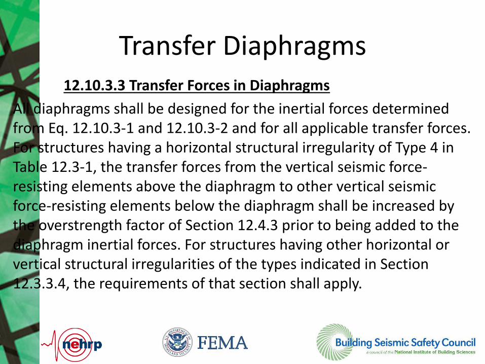
Transfer Diaphragms 12.10.3.3 Transfer Forces in Diaphragms
All diaphragms shall be designed for the inertial forces determined from Eq. 12.10.3-1 and 12.10.3-2 and for all applicable transfer forces. For structures having a horizontal structural irregularity of Type 4 in Table 12.3-1, the transfer forces from the vertical seismic force-resisting elements above the diaphragm to other vertical seismic force-resisting elements below the diaphragm shall be increased by the overstrength factor of Section 12.4.3 prior to being added to the diaphragm inertial forces. For structures having other horizontal or vertical structural irregularities of the types indicated in Section 12.3.3.4, the requirements of that section shall apply.

Transfer Diaphragms
ASCE 7-16 Section 12.10.1.1, 4th paragraph
ASCE 7-16 Section 12.10.3.3,
Exception: One- and two-family dwellings of light frame construction shall be permitted to use Ω0 = 1.0.

Collectors
12.10.3.4 Collectors - Seismic Design Categories C through F
In structures assigned to Seismic Design Category C, D, E, or F, collectors and their connections including connections to vertical elements shall be designed to resist 1.5 times the diaphragm inertial forces from Section 12.10.3.2 plus 1.5 times the design transfer forces.
EXCEPTION: 1. Any transfer force increased by the overstrength factor of Section 12.4.3 need not be further amplified by 1.5.

Precast Diaphragm Design

Design Method
1. Modify Fpx to develop desired yielding under:
– Design Earthquake
– Max Considered Earthquake
2. Prevent Shear Failure
Diaphragm Seismic Design Concept
Diaphragm 1 Plan View
Sh
ear
Wall
Sh
ear
Wall
Fpx = wpx
Shear on Diaphragm
Moment on Diaphragm
Fpx

Diaphragm Design Options
Elastic Design Option (EDO)
Basic Design Option (BDO) Reduced Design Option
(RDO)
Diaphragm remains elastic in DBE and MCE
Highest diaphragm design force
Connections can include LDE, MDE and HDE
Diaphragm remains elastic in DBE but Not
Necessarily in MCE
Lower diaphragm design force than EDO
Connections can include MDE and HDE
Some Diaphragm yielding in DBE,
significant in MCE
Lowest diaphragm design force
Connections must be High Deformation Elements (HDE)
Shear overstrength factor is needed
No shear overstrength needed since elastic
design
Shear overstrength factor is needed

Connector Qualification Protocol

Questions

1
Nonlinear Response-History Analysis: Contrast of Chapter 16 Versions for the
NEHRP Provisions and ASCE 7-16
Nonlinear Response-History Analysis: Contrast of Chapter 16 Versions for the
NEHRP Provisions and ASCE 7-16
Project by: Large Issue Team
Presented by: Curt B. Haselton, PhD, PEProfessor of Civil Engineering @ CSU, Chico
Co-Founder and CEO @ Seismic PerformancePrediction Program (SP3) [www.hbrisk.com]
Building Seismic Safety CouncilIssue Team 4 on Response History Analysis
BSSC PUC Meeting | August 29, 2017
2
ASCE7 Chapter 16 - Issue Team #4ASCE7 Chapter 16 - Issue Team #4
CB Crouse, URS Corp. Chung-Soo Doo, SOM Andy Fry, MKA Mahmoud Hachem, Degenkolb Ron Hamburger, SGH John Hooper, MKA Afshar Jalalian, R&C Charles Kircher, Kircher & Assoc. Silvia Mazzoni Bob Pekelnicky, Degenkolb Mark Sinclair Rafael Sabelli, Walter P Moore Reid Zimmerman, R&C
Curt Haselton, CSUC, Team Chair Jack Baker, Stanford University Finley Charney, Virginia Tech Greg Deierlein, Stanford Univ. Ken Elwood, Univ. of British Col. Steve Mahin, UC Berkeley Graham Powell, UC Berkeley Em. Jon Stewart, UCLA Andrew Whittaker, SUNY Buffalo Robert Hanson, FEMA Jay Harris, NIST Nico Luco, USGS Mike Tong, FEMA
Pra
ctiti
oner
Aca
dem
icG
over
nmen
t
Building Seismic Safety CouncilIssue Team 4 on Response History Analysis
3
Section 16.1: General RequirementsSection 16.2: Ground MotionsSection 16.3: Modeling and AnalysisSection 16.4: Analysis Results and Accept. CriteriaSection 16.5: Design Review
Chapter 16: Overall StructureChapter 16: Overall Structure
Building Seismic Safety CouncilIssue Team 4 on Response History Analysis

4
The basic structure of the design approach is:• Linear DBE-level analysis (to enforce minimum
base shear, basic load cases, etc.).• Nonlinear MCE-level response-history analysis.
Section 16.1 (General)Section 16.1 (General)
Building Seismic Safety CouncilIssue Team 4 on Response History Analysis

5
Ground motion level: • MCER (to better link to what is being assessed)
Number of ground motions: • 11 motions (to better estimate the mean responses)
Section 16.2 (Ground Motion)Section 16.2 (Ground Motion)
Building Seismic Safety CouncilIssue Team 4 on Response History Analysis

6
Target spectrum: • Method 1: Typical MCER spectrum• Method 2: Multiple “scenario” spectra (typically two)
Section 16.2 (Ground Motion)Section 16.2 (Ground Motion)
Building Seismic Safety CouncilIssue Team 4 on Response History Analysis

7
Selection of motions: • Same general language.• Added: “and shall have similar spectral shape to the
target spectrum.”• For near-fault: Include an appropriate ratio of pulse-
type motions (with ASCE-7-16 making this language more specific).
Section 16.2 (Ground Motion)Section 16.2 (Ground Motion)
Building Seismic Safety CouncilIssue Team 4 on Response History Analysis
8
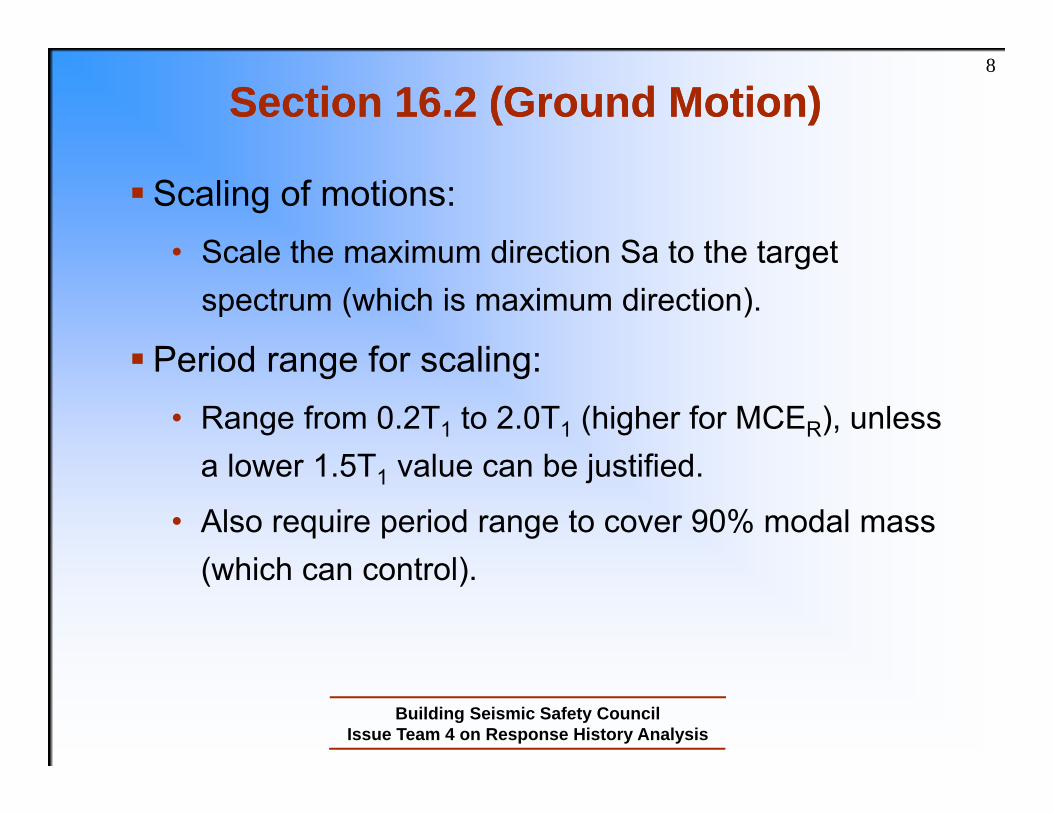
Scaling of motions: • Scale the maximum direction Sa to the target
spectrum (which is maximum direction).
Period range for scaling: • Range from 0.2T1 to 2.0T1 (higher for MCER), unless
a lower 1.5T1 value can be justified.
• Also require period range to cover 90% modal mass (which can control).
Section 16.2 (Ground Motion)Section 16.2 (Ground Motion)
Building Seismic Safety CouncilIssue Team 4 on Response History Analysis

9
Near-Fault versus Far-Field• BSSC: Left this fairly non-prescriptive.• ASCE-7-16: Added specificity in Chapter 11 (near-fault is R
< 15km if M > 7.0 and R < 10km if 7.0 > M > 6.5).
Orientation of Ground Motions: • Near-Fault: Apply pairs of records in FN/FP orientation• Far-Field:
• BSSC: Apply pairs of records with “random orientation”• ASCE-7-16: Added a more specific +/- 10% requirement)
• No need to rotate pairs 90 degrees
Section 16.2 (Ground Motion)Section 16.2 (Ground Motion)
Building Seismic Safety CouncilIssue Team 4 on Response History Analysis
10
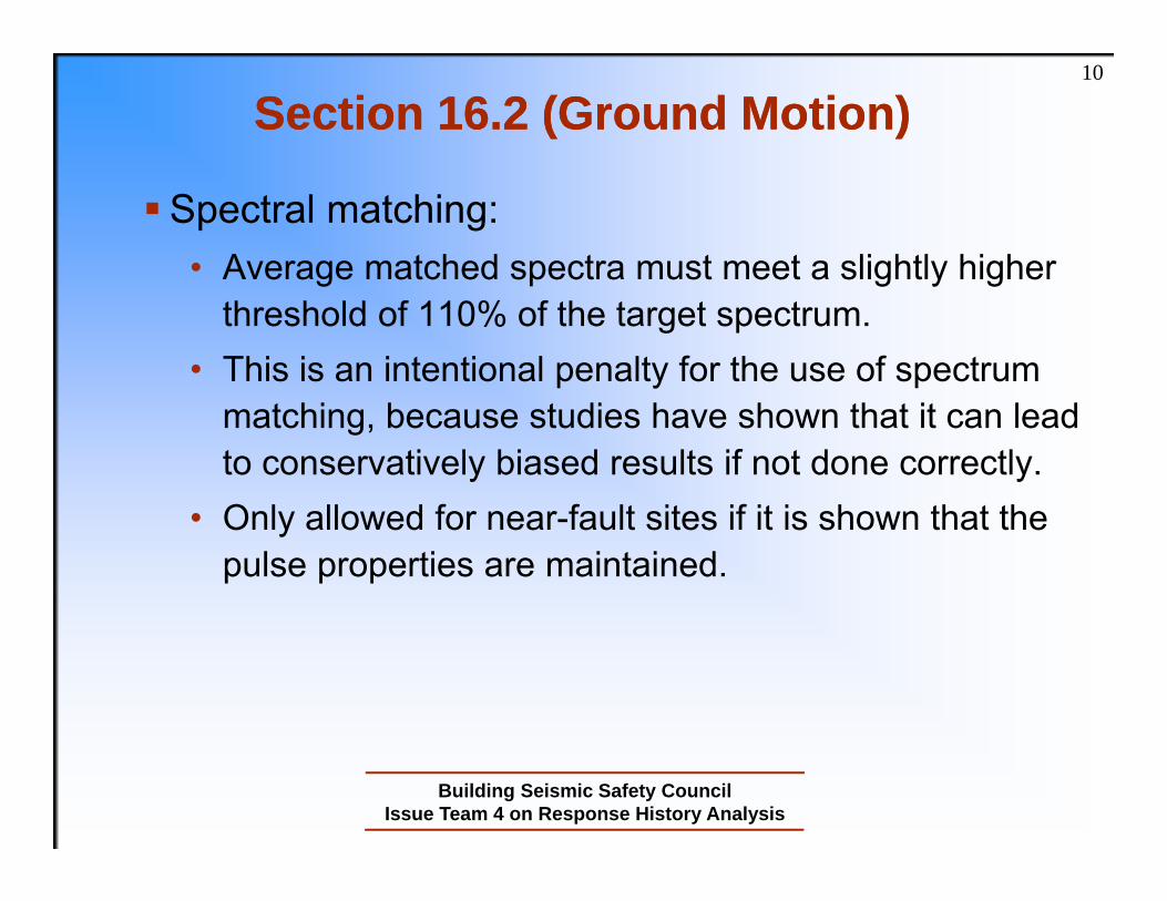
Spectral matching: • Average matched spectra must meet a slightly higher
threshold of 110% of the target spectrum. • This is an intentional penalty for the use of spectrum
matching, because studies have shown that it can lead to conservatively biased results if not done correctly.
• Only allowed for near-fault sites if it is shown that the pulse properties are maintained.
Section 16.2 (Ground Motion)Section 16.2 (Ground Motion)
Building Seismic Safety CouncilIssue Team 4 on Response History Analysis

11
This section says what to do but not how to do it.
This was intentionally not written to be a nonlinear analysis guideline.
Gravity loads: Specified cases and ASCE-7-16 added an exception.
Torsion:• Interesting topic with lots of divergent opinions!
• BSSC: Leave this to the linear design step.
• ASCE-7-16: Allow the above if no Type 1a/1b irregularity exists, otherwise require 5% mass offsets in the NL model.
Sec. 16.3 (Modeling & Analysis)Sec. 16.3 (Modeling & Analysis)
Building Seismic Safety CouncilIssue Team 4 on Response History Analysis

12
Big Focus: Develop acceptance criteria more clearly tied to the ASCE7 safety goals.
Explicit Goal: Acceptable collapse probability. Implicit Verification Approach: Use mean structural
responses (with 11 motions) to show compliance.
Section 16.4 (Accept. Criteria)Section 16.4 (Accept. Criteria)
Building Seismic Safety CouncilIssue Team 4 on Response History Analysis

13
Force-controlled (brittle) components:
Section 16.4 (Accept. Criteria)Section 16.4 (Accept. Criteria)
Building Seismic Safety CouncilIssue Team 4 on Response History Analysis

14
Force-controlled (brittle) components:
Section 16.4 (Accept. Criteria)Section 16.4 (Accept. Criteria)
for “critical” (same as PEER-TBI) for “ordinary” for “non-critical” (judgment)
Fu = mean demand (from 11 motions) [ASCE-7-16: Modified equation format and only scale the non-seismic loads]
Fe = expected strength
Critical = failure causes immediate global collapseOrdinary = failure causes local collapse (one bay)Non-critical = failure does not cause collapse
Building Seismic Safety CouncilIssue Team 4 on Response History Analysis

15
Deformation-controlled (ductile) components:• BSSC:
• Similar statistical approach used (as with force-controlled components).
• “Pre-approved” uses of ASCE41 are also provided.
• ASCE-7-16:• Swapped the above, so the ASCE41 criteria are the
default and the statistical approach is an alternative.
Section 16.4 (Accept. Criteria)Section 16.4 (Accept. Criteria)
Building Seismic Safety CouncilIssue Team 4 on Response History Analysis

16
Drift limits:• Mean drift ≤ 2.0*(normal limit)• The factor of two comes from: 1.5 = MCE / DBE 1.25 = Approx. ratio of R / Cd 1.1 = A little extra because we trust NL RHA
more
Section 16.4 (Accept. Criteria)Section 16.4 (Accept. Criteria)
Building Seismic Safety CouncilIssue Team 4 on Response History Analysis

17
Statistical collapse study:
Building Seismic Safety CouncilIssue Team 4 on Response History Analysis
Section 16.4 (Accept. Criteria)Section 16.4 (Accept. Criteria)

18
Statistical collapse study:
Building Seismic Safety CouncilIssue Team 4 on Response History Analysis
Section 16.4 (Accept. Criteria)Section 16.4 (Accept. Criteria)

19
Final Criterion for Collapses, or “Unacceptable Responses”: • Basic Case: Allow up to 1/11 “collapses” but not 2/11.• With Spectral Matching: Require 0/11 collapses.• For Risk Categories III-IV: Require 0/11 collapses.
• ASCE-7-16: Same but reworded as an exception.
Section 16.4 (Accept. Criteria)Section 16.4 (Accept. Criteria)
Building Seismic Safety CouncilIssue Team 4 on Response History Analysis

20
Typical requirements and language…not covered here…
Section 16.5 (Design Review)Section 16.5 (Design Review)
Building Seismic Safety CouncilIssue Team 4 on Response History Analysis

21
ASCE 7 Chapter 16 Project Documentation: Earthquake Spectra papers just published:
1. Provisions Development (1 of 2)2. Provisions Development (2 of 2)3. Example Applications4. Evaluation Studies
More Information: PublicationsMore Information: Publications
Recent Advances in Ground Motion Selection and Scaling

22
Thanks you for your time.
Please contact me if there is anything else I can do to help with this.
Contact:• E-mail: [email protected]
• Website: www.hbrisk.com
• Direct: (530) 514-8980
Questions/Comments?Questions/Comments?
Building Seismic Safety CouncilIssue Team 4 on Response History Analysis

EERI Seminar on Next Generation Attenuation Models
New Site-Specific Ground Motion Requirements of
ASCE 7-16
2017 SEAOC Convention – San Diego - September 14, 2017
Charlie Kircher Kircher & AssociatesPalo Alto, California

New Site-Specific Ground Motion Requirements of ASCE 7-16 – Charlie Kircher
Content
1. Background Material
2. The “Problem” with ELF (MRSA) Methods
3. Interim Solution (ASCE 7-16)
4. New Site-Specific Requirements of Section
11.4.8
5. Examples of Seismic Response Coefficient
6. Summary and Conclusion

New Site-Specific Ground Motion Requirements of ASCE 7-16 – Charlie Kircher
Seismic Code Development Process
• 2018 International Building Code (IBC)
– International Code Council, Codes and Standards
• IBC Structural Committee
• ASCE 7-16 - Minimum Design Loads on
Buildings and Other Structures
– Structural Engineering Institute (SEI) of the American
Society of Civil Engineers (ASCE)
• ASCE 7 Seismic Subcommittee (SSC)
• 2015 NEHRP Recommended Provisions
– Building Seismic Safety Council (BSSC) for the
Federal Emergency Management Agency (FEMA)
• Provisions Update Committee (PUC)
New Site-Specific Ground Motion Requirements of ASCE 7-16 – Charlie Kircher
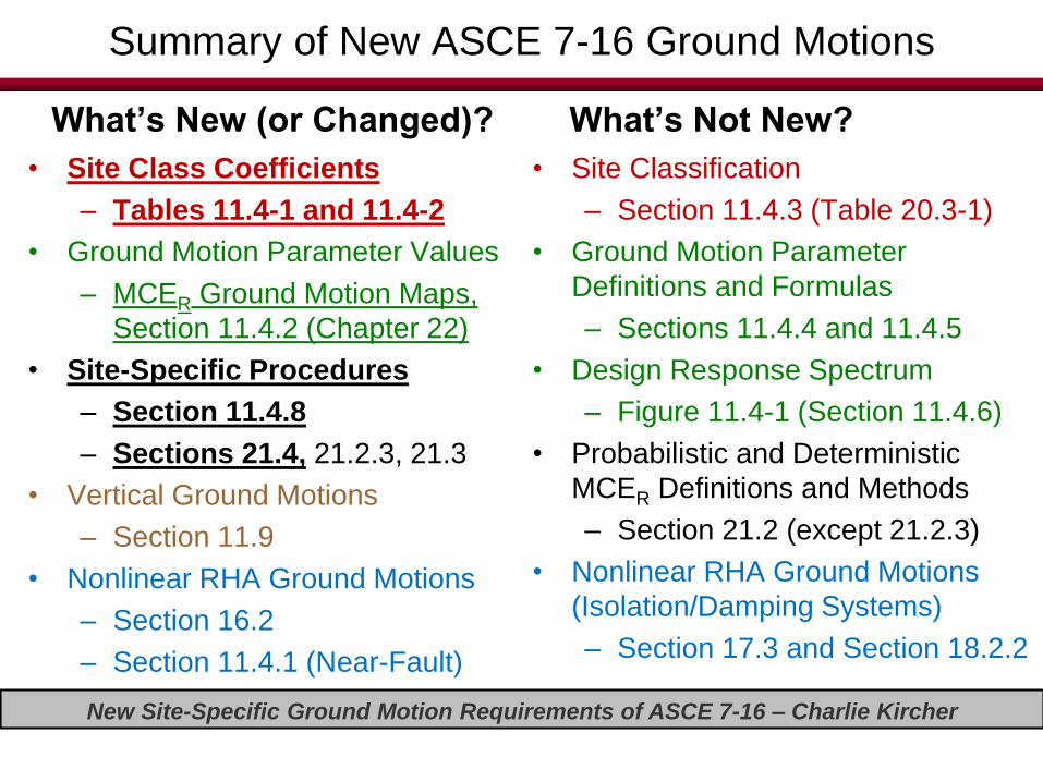
Summary of New ASCE 7-16 Ground Motions
What’s New (or Changed)?
• Site Class Coefficients– Tables 11.4-1 and 11.4-2
• Ground Motion Parameter Values
– MCER Ground Motion Maps,
Section 11.4.2 (Chapter 22)
• Site-Specific Procedures– Section 11.4.8– Sections 21.4, 21.2.3, 21.3
• Vertical Ground Motions
– Section 11.9
• Nonlinear RHA Ground Motions
– Section 16.2
– Section 11.4.1 (Near-Fault)
What’s Not New?
• Site Classification
– Section 11.4.3 (Table 20.3-1)
• Ground Motion Parameter
Definitions and Formulas
– Sections 11.4.4 and 11.4.5
• Design Response Spectrum
– Figure 11.4-1 (Section 11.4.6)
• Probabilistic and Deterministic
MCER Definitions and Methods
– Section 21.2 (except 21.2.3)
• Nonlinear RHA Ground Motions
(Isolation/Damping Systems)
– Section 17.3 and Section 18.2.2
New Site-Specific Ground Motion Requirements of ASCE 7-16 – Charlie Kircher
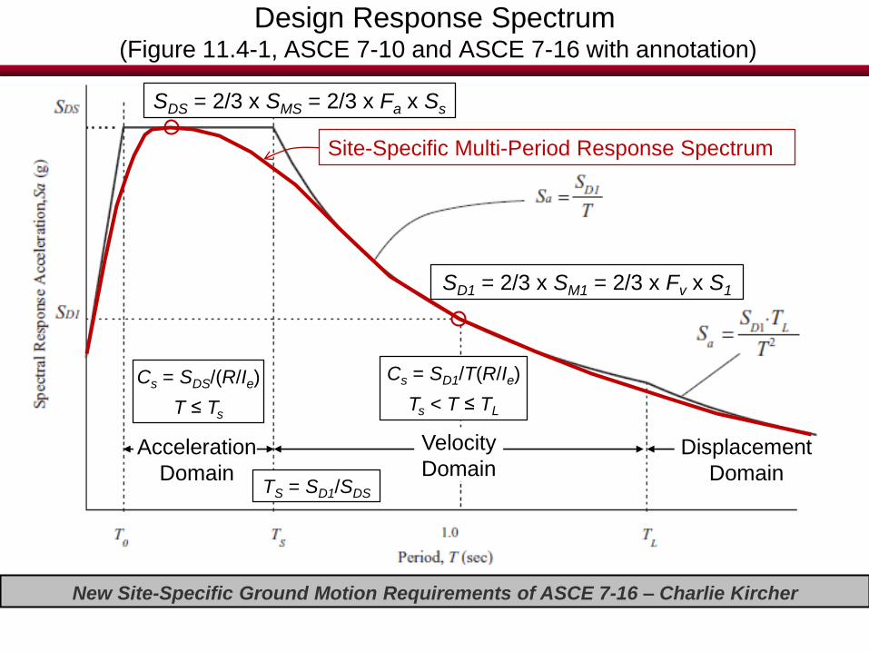
Design Response Spectrum(Figure 11.4-1, ASCE 7-10 and ASCE 7-16 with annotation)
Acceleration
Domain
Velocity
DomainDisplacement
Domain
SDS = 2/3 x SMS = 2/3 x Fa x Ss
TS = SD1/SDS
SD1 = 2/3 x SM1 = 2/3 x Fv x S1
Cs = SDS/(R/Ie)
T ≤ Ts
Cs = SD1/T(R/Ie)
Ts < T ≤ TL
Site-Specific Multi-Period Response Spectrum
New Site-Specific Ground Motion Requirements of ASCE 7-16 – Charlie Kircher
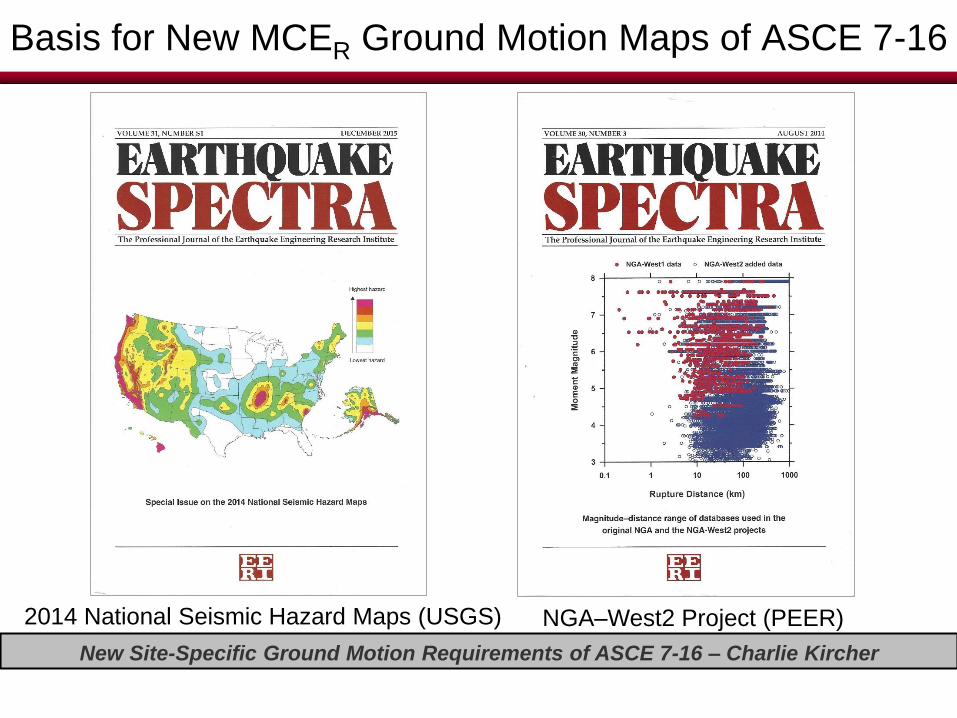
Basis for New MCER Ground Motion Maps of ASCE 7-16
2014 National Seismic Hazard Maps (USGS) NGA–West2 Project (PEER)

New Site-Specific Ground Motion Requirements of ASCE 7-16 – Charlie Kircher
Research Projects Contributing to 2014 USGS NSHM Updates
(Luco, USGS)
+ Dozens of other updates summarized in the Commentary to Chapter
22 of ASCE 7-16 and explained in the December 2015 Special Issue
of Earthquake Spectra journal
Project Name Lead(s) Duration SponsorsCentral & Eastern US Seismic
Source Characterization for
Nuclear Facilities (CEUS-SSC)Consultants 2008-2011
US DOE,
EPRI, US
NRC
Uniform California Earthquake
Rupture Forecast, Version 3
(UCERF3)
USGS,
CGS, SCEC
(WGCEP)
2010-2013 CEA
Next Generation Attenuation
Relations for Western US,
Version 2 (NGA-West2)PEER 2010-2013
CEA,
Caltrans,
PG&E

New Site-Specific Ground Motion Requirements of ASCE 7-16 – Charlie Kircher
PEER NGA-West1 and NGA-West2 Earthquake Databases and GMPEs(Bozorgnia et al., Earthquake Spectra, Vol. 30, No. 3, August 2014, EERI)
NGA-West1 Database – 3,550 Records
(West1 GMPEs used for ASCE 7-10 maps)
NGA-West2 Database – 21,332 Records
(West2 GMPEs used for ASCE 7-16 maps)

New Site-Specific Ground Motion Requirements of ASCE 7-16 – Charlie Kircher
0.0
0.2
0.4
0.6
0.8
1.0
1.2
1.4
1.6
1.8
2.0
2.2
2.4
0.1 1.0 10.0
Sp
ectr
al A
cce
lera
tio
n (
g)
Period (seconds)
West1 - vs,30 = 5,000 fps
West1 - vs,30 = 2,500 fps
West1 - vs,30 = 1,200 fps
West1 - vs,30 = 600 fps
West2 - vs,30 = 5,000 fps
West2 - vs,30 = 2,500 fps
West2 - vs,30 = 1,200 fps
West2 - vs,30 = 600 fps
Example Comparison of Deterministic MCER Ground MotionsNGA West1 and NGA West2 GMPEs (M7.0 at Rx = 6 km, Site Class boundaries)
PEER NGA GMPE spreadsheet calculations: West1 based on Al Atik, 2009, West2 based on Seyhan, 2014)
West2 is 45% greater
than West1 at 0.5s
(vs,30 = 600 fps)
West2 is 27% greater
than West1 at 0.3s
(vs,30 = 1,200 fps)

New Site-Specific Ground Motion Requirements of ASCE 7-16 – Charlie Kircher
New Values of the Site Coefficient, Fa (Table 11.4-1 of ASCE7-16)(shown as proposed changes to ASCE 7-10)
Table 11.4-1 Site Coefficient, Fa
Site
Class
Mapped Risk-Targeted Maximum Considered Earthquake (MCER) Spectral Response
Acceleration Parameter at Short Period
SS 0.25 SS = 0.5 SS = 0.75 SS = 1.0 SS = 1.25 SS ≥ 1.5
A 0.8 0.8 0.8 0.8 0.8 0.8
B 1.0 0.9 1.0 0.9 1.0 0.9 1.0 0.9 1.0 0.9 0.9
C 1.2 1.3 1.2 1.3 1.1 1.2 1.0 1.2 1.0 1.2 1.2
D 1.6 1.4 1.2 1.1 1.0 1.0
E 2.5 2.4 1.7 1.2 1.3 0.9 1.1 0.9 1.0 0.8
F See Section 11.4.7
Note: Use straight-line interpolation for intermediate values of SS. At the Site Class B-C boundary, Fa = 1.0 for all Ss levels. If site
classes A or B is established without the use of on-site geophysical measurements of shear wave velocity, use Fa = 1.0.
Note – Site Class B is no longer the “reference” site class of MCER ground motion parameters
Ss and S1 (i.e., new coefficients reflect Site Class BC boundary of 2,500 f/s) and Site Class D is
no longer the “default” site class (when Site Class C amplification is greater, i.e., SS ≥ 1.0)
See Section 11.4.8
Note – Site-Specific analysis required for Site Class E sites where SS ≥ 1.0 w/exception
11.4.8

New Site-Specific Ground Motion Requirements of ASCE 7-16 – Charlie Kircher
New Values of the Site Coefficient, Fv (Table 11.4-2 of ASCE7-16)(shown as proposed changes to ASCE 7-10)
Table 11.4-2 Site Coefficient, Fv
Site
Class
Mapped Risk-Targeted Maximum Considered Earthquake (MCER)
Spectral Response Acceleration Parameter at 1-s Period
S1 0.1 S1 = 0.2 S1 = 0.3 S1 = 0.4 S1 = 0.5 S1 0.6
A 0.8 0.8 0.8 0.8 0.8 0.8
B 1.0 0.8 1.0 0.8 1.0 0.8 1.0 0.8 1.0 0.8 0.8
C 1.7 1.5 1.6 1.5 1.5 1.4 1.5 1.3 1.5 1.4
D 2.4 2.0 2.2 1.8 2.0 1.6 1.9 1.5 1.8 1.7
E 3.5 4.2 3.2 3.3 2.8 2.4 2.4 2.2 2.0
F See Section 11.4.7
Note: Use straight-line interpolation for intermediate values of S1. At the Site Class B-C boundary, Fv = 1.0 for all S1 levels. If site
classes A or B are established without the use of on-site geophysical measurements of shear wave velocity, use Fv = 1.0.
Note – Site Class B is no longer the “reference” site class of MCER ground motion
parameters Ss and S1 (i.e., new coefficients reflect Site Class BC boundary of 2,500 f/s).
Note - Site-Specific analysis required for Site Class D sites where S1 ≥ 0.2 w/exceptions
11.4.8
See Section 11.4.8
Site-Specific analysis required for Site Class E sites where S1 ≥ 0.2 w/o exception

New Site-Specific Ground Motion Requirements of ASCE 7-16 – Charlie Kircher
The “Problem” with ELF (MRSA) Methods
• Use of only two response periods (0.2s and 1.0s) to define ELF
(and MRSA) design forces is not sufficient, in general, to
accurately represent response spectral acceleration for all
design periods of interest
– Reasonably Accurate (or Conservative) – When peak
MCER response spectral acceleration occurs at or near 0.2s
and peak MCER response spectral velocity occurs at or near
1.0s for the site of interest
– Potentially Non-conservative – When peak MCER
response spectral velocity occurs at periods greater than
1.0s for the site of interest
• Softer soil sites whose seismic hazard is dominated by
large magnitude events

New Site-Specific Ground Motion Requirements of ASCE 7-16 – Charlie Kircher
Design Response Spectrum(Figure 11.4-1, ASCE 7-10 and ASCE 7-16 with annotation)
Acceleration
Domain
Velocity
DomainDisplacement
Domain
SDS = 2/3 x SMS = 2/3 x Fa x Ss
TS = SD1/SDS
SD1 = 2/3 x SM1 = 2/3 x Fv x S1
Cs = SDS/(R/Ie)
T ≤ Ts
Cs = SD1/T(R/Ie)
Ts < T ≤ TL
Site-Specific Multi-Period Response Spectrum

New Site-Specific Ground Motion Requirements of ASCE 7-16 – Charlie Kircher
Example Design Spectra - Deterministic MCER Ground Motions (ASCE 7-16)
PEER NGA West2 GMPEs (M8.0 at Rx = 8.5 km, Site Class boundaries)
0.0
0.5
1.0
1.5
2.0
2.5
0.1 1.0 10.0
Sp
ectr
al A
ccele
ration
(g)
Period (seconds)
Site Class AB - vs,30 = 5,000 fps
Site Class BC - vs,30 = 2,500 fps
Site Class CD - vs,30 = 1,200 fps
Site Class DE - vs,30 = 600 fps

New Site-Specific Ground Motion Requirements of ASCE 7-16 – Charlie Kircher
0.0
0.2
0.4
0.6
0.8
1.0
1.2
1.4
1.6
1.8
2.0
2.2
2.4
2.6
0.1 1.0 10.0
Response S
pectr
al A
ccele
rtation (
g)
Period (seconds)
MCEr Multi-Period Response Spectrum - Site Class BC
MCEr Multi-Period Response Spectrum - Site Class C
Design Multi-Period Response Spectrum - Site Class C
Example ELF “Design Spectrum” - ASCE 7-16 w/o New Site-Specific Requirements
M8.0 earthquake ground motions at RX = 9.9 km, Site Class C
0.0
0.2
0.4
0.6
0.8
1.0
1.2
1.4
1.6
1.8
2.0
2.2
2.4
2.6
0.1 1.0 10.0
Response S
pectr
al A
ccele
rtation (
g)
Period (seconds)
MCEr Multi-Period Response Spectrum - Site Class BC
MCEr Multi-Period Response Spectrum - Site Class C
Design Multi-Period Response Spectrum - Site Class C
ELF Design Spectrum (Cs x R/Ie) - ASCE 7-16 w/o SSAF
ELF Design Spectrum
Ss = 1.5
Fa = 1.2
SMS = Fa x Ss = 1.8
SDS = 2/3 x SMS = 1.2
S1 = 0.72
Fv = 1.4
SM1 = Fv x S1 = 1.01
SD1 = 2/3 x SM1 = 0.67

New Site-Specific Ground Motion Requirements of ASCE 7-16 – Charlie Kircher
0.0
0.2
0.4
0.6
0.8
1.0
1.2
1.4
1.6
1.8
2.0
2.2
2.4
2.6
0.1 1.0 10.0
Response S
pectr
al A
ccele
rtation (
g)
Period (seconds)
MCEr Multi-Period Response Spectrum - Site Class BC
MCEr Multi-Period Response Spectrum - Site Class D
Design Multi-Period Response Spectrum - Site Class D
Example ELF “Design Spectrum” - ASCE 7-16 w/o New Site-Specific Requirements
M8.0 earthquake ground motions at RX = 9.9 km, Site Class D
0.0
0.2
0.4
0.6
0.8
1.0
1.2
1.4
1.6
1.8
2.0
2.2
2.4
2.6
0.1 1.0 10.0
Response S
pectr
al A
ccele
rtation (
g)
Period (seconds)
MCEr Multi-Period Response Spectrum - Site Class BC
MCEr Multi-Period Response Spectrum - Site Class D
Design Multi-Period Response Spectrum - Site Class D
ELF Design Spectrum (Cs x R/Ie) - ASCE 7-16 w/o SSAF
ELF Design Spectrum
Ss = 1.5
Fa = 1.0
SMS = Fa x Ss = 1.5
SDS = 2/3 x SMS = 1.0
S1 = 0.72
Fv = 1.7
SM1 = Fv x S1 = 1.22
SD1 = 2/3 x SM1 = 0.82
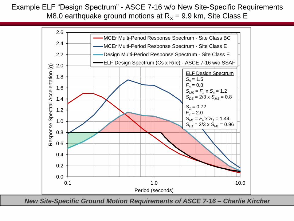
New Site-Specific Ground Motion Requirements of ASCE 7-16 – Charlie Kircher
0.0
0.2
0.4
0.6
0.8
1.0
1.2
1.4
1.6
1.8
2.0
2.2
2.4
2.6
0.1 1.0 10.0
Response S
pectr
al A
ccele
rtation (
g)
Period (seconds)
MCEr Multi-Period Response Spectrum - Site Class BC
MCEr Multi-Period Response Spectrum - Site Class E
Design Multi-Period Response Spectrum - Site Class E
Example ELF “Design Spectrum” - ASCE 7-16 w/o New Site-Specific Requirements
M8.0 earthquake ground motions at RX = 9.9 km, Site Class E
0.0
0.2
0.4
0.6
0.8
1.0
1.2
1.4
1.6
1.8
2.0
2.2
2.4
2.6
0.1 1.0 10.0
Response S
pectr
al A
ccele
rtation (
g)
Period (seconds)
MCEr Multi-Period Response Spectrum - Site Class BC
MCEr Multi-Period Response Spectrum - Site Class E
Design Multi-Period Response Spectrum - Site Class E
ELF Design Spectrum (Cs x R/Ie) - ASCE 7-16 w/o SSAF
ELF Design Spectrum
Ss = 1.5
Fa = 0.8
SMS = Fa x Ss = 1.2
SDS = 2/3 x SMS = 0.8
S1 = 0.72
Fv = 2.0
SM1 = Fv x S1 = 1.44
SD1 = 2/3 x SM1 = 0.96

New Site-Specific Ground Motion Requirements of ASCE 7-16 – Charlie Kircher
Long-Term Solution (Project 17/ASCE 7-22)
• Develop and adopt multi-period design spectrum
approach
– Not feasible in current code cycle (ASCE 7-16)
• Multi-period spectrum approach will require:
– Reworking of seismic design requirements and criteria now
based on two response periods
– Development of new ground motion design parameters (by
the USGS) for each new response period of interest
– Development of new site factors for each new response
period of interest (or embed site effects directly in ground
motion design values)

New Site-Specific Ground Motion Requirements of ASCE 7-16 – Charlie Kircher
Interim Solution (ASCE 7-16)
• Require site-specific analysis when site factors
(alone) are not sufficiently conservative
• Provide exceptions to site-specific requirements
that allow designers the option to design for
conservative forces in lieu of performing a site-
specific analysis
• Perform a study to provide the basis for the new
requirements and conservative criteria of
exceptions

New Site-Specific Ground Motion Requirements of ASCE 7-16 – Charlie Kircher
Interim Solution Options (BSSC PUC)
• Option 1 - Re-formulate seismic parameters to eliminate
potential non-conservatism in ELF (and MRSA) seismic forces
• Option 2 - Require site-specific analysis when ELF (and
MSRA) seismic forces could be potentially non-conservative

New Site-Specific Ground Motion Requirements of ASCE 7-16 – Charlie Kircher
Interim Solution Homework (NIBS BSSC “ELF” Study)
• FEMA-funded NIBS BSSC study (Kircher & Associates):
“Investigation of an Identified Short-coming in the Seismic Design Procedures of
ASCE 7-10 and Development of Recommended Improvements For ASCE 7-16”
https://www.nibs.org/resource/resmgr/BSSC2/Seismic_Factor_Study.pdf
• Study Advisors and Contributors:
– Nico Luco (USGS)
– Sanaz Rezaeian (USGS)
– C. B. Crouse (URS)
– Jonathan Stewart (UCLA)
– Kevin Milner (SCEC)
– David Bonnevile (Degenkolb) – BSSC PUC Chair
– John Hooper (MKA) – ASCE 7-16 SSC Chair
• PEER Center - Next Generation Attenuation Relations
– Linda Al Atik (PEER NGA West1 GMPEs spreadsheet)
– Emil Seyhan (PEER NGA West2 GMPEs spreadsheet)

New Site-Specific Ground Motion Requirements of ASCE 7-16 – Charlie Kircher
Option 1 - Spectrum Shape Adjustment Factor Reformulation(Figure 11.4-1 annotated to show proposed new spectrum shape Adjustment Factors, Ca and Cv)
Acceleration
Domain
Velocity
DomainDisplacement
DomainTS = SD1/SDS
SD1 = 2/3 x SM1 = 2/3 x Cv x Fv x S1
Cs = SDS/(R/Ie)
T ≤ Ts
Cs = SD1/T(R/Ie)
Ts < T ≤ TL
SDS = 2/3 x SMS = 2/3 x Ca x Fa x Ss Spectrum Shape
Adjustment Factors
Ca = f{Ss, SC} ≥ 0.9
Cv = f{S1, SC, TL} ≥ 1.0

New Site-Specific Ground Motion Requirements of ASCE 7-16 – Charlie Kircher
Example Values of SDS and SD1 using the New Requirements of Section 21.4
(M8.0 earthquake ground motions at RX = 9.9 km, Site Class DE)
0.0
0.2
0.4
0.6
0.8
1.0
1.2
1.4
1.6
1.8
2.0
2.2
2.4
2.6
0.1 1.0 10.0
Response S
pectr
al A
ccele
rtation (
g)
Period (seconds)
MCEr Multi-Period Response Spectrum - Site Class BC
MCEr Multi-Period Response Spectrum - Site Class DE
Design Multi-Period Response Spectrum - Site Class DE
ELF Design Spectrum (Cs x R/Ie) - ASCE 7-16
SD1 = max(T x Sa[1s ≤ T ≤ 5s])
SDS = Max(0.9 x Sa[0.2s < T ≤ 5s])

New Site-Specific Ground Motion Requirements of ASCE 7-16 – Charlie Kircher
Example Calculation of Spectrum Shape Factors, Ca and Cv
(M8.0 earthquake ground motions at RX = 9.9 km, Site Class DE)
0.0
0.2
0.4
0.6
0.8
1.0
1.2
1.4
1.6
1.8
2.0
2.2
2.4
2.6
0.1 1.0 10.0
Response S
pectr
al A
ccele
rtation (
g)
Period (seconds)
MCEr Multi-Period Response Spectrum - Site Class BC
MCEr Multi-Period Response Spectrum - Site Class DE
Design Multi-Period Response Spectrum - Site Class DE
ELF Design Spectrum (Cs x R/Ie) - ASCE 7-16
Example Values of Ca and Cv
Ca = CFa/Fa = 1.07/0.9 = 1.2
Cv = CFv /Fv = 3.27/1.85 = 1.8
SD1 = max(T x Sa[1s ≤ T ≤ 5s])
Calculation of Parameters CFa and CFv
CFa = SDS/(2/3 Ss) = 0.9 x 1.19g)/(2/3 x 1.5g) = 1.07
CFv = SD1/(2/3 S1) = 3s x 0.48g/s/(2/3 x 0.66g) = 3.27
SDS = Max(0.9 x Sa[0.2s < T ≤ 5s])
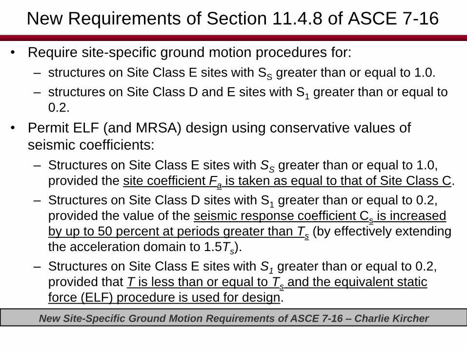
New Site-Specific Ground Motion Requirements of ASCE 7-16 – Charlie Kircher
New Requirements of Section 11.4.8 of ASCE 7-16
• Require site-specific ground motion procedures for:
– structures on Site Class E sites with SS greater than or equal to 1.0.
– structures on Site Class D and E sites with S1 greater than or equal to
0.2.
• Permit ELF (and MRSA) design using conservative values of
seismic coefficients:
– Structures on Site Class E sites with SS greater than or equal to 1.0,
provided the site coefficient Fa is taken as equal to that of Site Class C.
– Structures on Site Class D sites with S1 greater than or equal to 0.2,
provided the value of the seismic response coefficient Cs is increased
by up to 50 percent at periods greater than Ts (by effectively extending
the acceleration domain to 1.5Ts).
– Structures on Site Class E sites with S1 greater than or equal to 0.2,
provided that T is less than or equal to Ts and the equivalent static
force (ELF) procedure is used for design.

New Site-Specific Ground Motion Requirements of ASCE 7-16 – Charlie Kircher
Example Values of the Design Coefficient (Cs)
• One (High Seismic) Site - Ss = 1.5 g, S1 – 0.6 g
• Two Structural Systems:
– 4-Story Steel SMF Building – Ta = 0.59 s (acceleration domain)
– 15-Story Steel SMF Building – Ta = 1.62 s (velocity domain)
• Three Site Conditions (each system) – Site Class B, C, D and E
• Three Sets of ELF Design Criteria (each example):
– ASCE 7-10 – Existing design requirements of ASCE 7-10
– ASCE 7-16 – New design requirements of ASCE 7-16 including the new site-specific requirements and exceptions of Section 11.4.8
– ELF Study - What if ASCE 7-16 had adopted the spectrum shape
adjustment factors (SSAFs) of BSSC PUC “ELF” Study (Kircher et al.,
2015) to modify the frequency content of the Design Spectrum?

New Site-Specific Ground Motion Requirements of ASCE 7-16 – Charlie Kircher
0.000
0.020
0.040
0.060
0.080
0.100
0.120
0.140
0.1 1 10
De
sig
n C
oe
ffic
ien
t, C
s (
g)
Period (seconds)
ASCE 7-10
ASCE 7-16
ELF Study
Minimimum Cs Criteria:Cs ≥ 0.044SDS ≥ 0.01 (Eq. 12.8-5) Cs ≥ 0.5S1/(R/Ie) (Eq. 12.8-6)
Example Comparison of the Design Coefficient (Cs)
4-Story and 15-Story Steel Special Moment Frame Buildings - Site Class B
Ta = 0.59 sTa = 1.62 s
Material Steel Site Class BSystem MF v s,30 (fps) 3,500
Detailing Special S s 1.50Floors 4 (16) S 1 0.60
Height (ft) 45 (160) SDC DT a (s) 0.59 (1.62) R 8

New Site-Specific Ground Motion Requirements of ASCE 7-16 – Charlie Kircher
0.000
0.020
0.040
0.060
0.080
0.100
0.120
0.140
0.160
0.1 1 10
De
sig
n C
oe
ffic
ien
t, C
s (
g)
Period (seconds)
ASCE 7-10
ASCE 7-16
ELF Study
Minimimum Cs Criteria:Cs ≥ 0.044SDS ≥ 0.01 (Eq. 12.8-5) Cs ≥ 0.5S1/(R/Ie) (Eq. 12.8-6)
Example Comparison of the Design Coefficient (Cs)
4-Story and 15-Story Steel Special Moment Frame Buildings - Site Class C
Ta = 0.59 s
Ta = 1.62 s
Material Steel Site Class CSystem MF v s,30 (fps) 1,750
Detailing Special S s 1.50Floors 4 (16) S 1 0.60
Height (ft) 45 (160) SDC DT a (s) 0.59 (1.62) R 8
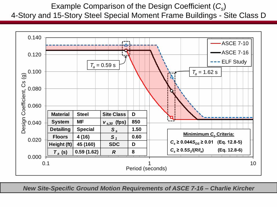
New Site-Specific Ground Motion Requirements of ASCE 7-16 – Charlie Kircher
0.000
0.020
0.040
0.060
0.080
0.100
0.120
0.140
0.1 1 10
De
sig
n C
oe
ffic
ien
t, C
s (
g)
Period (seconds)
ASCE 7-10
ASCE 7-16
ELF Study
Minimimum Cs Criteria:Cs ≥ 0.044SDS ≥ 0.01 (Eq. 12.8-5) Cs ≥ 0.5S1/(R/Ie) (Eq. 12.8-6)
Example Comparison of the Design Coefficient (Cs)
4-Story and 15-Story Steel Special Moment Frame Buildings - Site Class D
Ta = 0.59 s
Ta = 1.62 s
Material Steel Site Class DSystem MF v s,30 (fps) 850
Detailing Special S s 1.50Floors 4 (16) S 1 0.60
Height (ft) 45 (160) SDC DT a (s) 0.59 (1.62) R 8

New Site-Specific Ground Motion Requirements of ASCE 7-16 – Charlie Kircher
0.000
0.020
0.040
0.060
0.080
0.100
0.120
0.140
0.160
0.1 1 10
Desig
n C
oeffic
ient,
Cs (
g)
Period (seconds)
ASCE 7-10
ASCE 7-16
ELF Study
Minimimum Cs Criteria:Cs ≥ 0.044SDS ≥ 0.01 (Eq. 12.8-5) Cs ≥ 0.5S1/(R/Ie) (Eq. 12.8-6)
Example Comparison of the Design Coefficient (Cs)
4-Story and 15-Story Steel Special Moment Frame Buildings - Site Class E
Ta = 0.59 s
Ta = 1.62 s
Material Steel Site Class ESystem MF v s,30 (fps) 500
Detailing Special S s 1.50Floors 4 (16) S 1 0.60
Height (ft) 45 (160) SDC DT a (s) 0.59 (1.62) R 8

New Site-Specific Ground Motion Requirements of ASCE 7-16 – Charlie Kircher
Summary and Conclusions
• Impact on New Building Design. The new site-specific requirements
(and exceptions) of Section 11.4.8 of ASCE 7-16 will have a significant
impact on the design of mid-period buildings at Site Class D and E sites
(e.g., 50+ percent increase in design forces).
– Existing Building Safety. Implications for existing buildings (??).
• Interim Solution. The new site-specific design requirements of
Section 11.4.8 of ASCE 7-16 provide an interim solution that can and
should be replaced by a more appropriate long-term solution in the next
Code cycle (ASCE 7-22).
• Long-Term Solution. A long-term solution would necessarily include
seismic criteria described by multi-period MCER response spectra
(currently under development by Project ‘17).
– Design Spectrum Shape. Ideally, multi-period design spectra
directly incorporate site, basin and other effects that influence the
shape (i.e., frequency content) of the design spectrum.

New Site-Specific Ground Motion Requirements of ASCE 7-16 – Charlie Kircher
Questions?