development of wide-area protection and coordination for
TRANSCRIPT

International Journal of Smart Grid and Clean Energy
Development of wide-area protection and coordination for
PEA electrical transmission systems
A. Supannon a,b
, S. Premrudeepreechacharn b, and P. Pachanapan
c
a PhD’s Degree Program in Electrical Engineering, Faculty of Engineering, Chiang Mai University, Chiang Mai, 50200, Thailand
b Department of Electrical Engineering, Faculty of Engineering, Chiang Mai University, Chiang Mai, 50200, Thailand c Department of Electrical and Computer Engineering, Faculty of Engineering, Naresuan University, Phitsanulok, 65000, Thailand
Abstract
This paper presents the methodology of development wide-area protection and coordination (WAPC) for Provincial
Electricity Authority (PEA) electrical transmission systems. The methodology of development WAPC consist of
three main parts: the database management system, the evaluated operation of relays and the reconfiguration of
miscoordinated relays. DIgSILENT Stationware software is used as a database management software and
DIgSILENT PowerFactory is used as an analysis software. This proposed method could be applied to solve
miscoordinated relays and to manage data. The proposed method has been implemented in the 115 kV southern 1
region of PEA transmission systems. The test results show the proposed method could be implemented to improve
relay coordination. The method is easy to use, flexible and saving time.
Keywords: Wide-Area Protection and Coordination (WAPC), miscoordinated relays, DIgSILENT Stationware,
DIgSILENT PowerFactory
1. Introduction
Currently, the electrical transmission systems of the Provincial Electricity Authority (PEA) contain
with various types and characters such as radial and closed loop operation. In recent years, the distributed
generation (DG) from renewable energy sources has been undergoing consideration for connected
directly to PEA transmission system, which cause the control and monitoring system of the power grid to
be more complex. Consequently, the designing of protection schemes is very difficult. The protection
schemes are designed in a variety of schemes due to many protective devices are located within the
transmission system and they should be coordinate correctly. This designing of protection scheme is
called “Wide-Area Protection and Coordination (WAPC)”. A WAPC system needs a big database management system to handle with a large amount of the
protective device's data. In addition, the electrical transmission systems may be changed the electrical
configuration or the electrical transmission systems installed the DG which affects to the protection
setting value, so the database information must always be updated. Moreover, the protection device
settings must be regularly monitored and updated for protective devices are coordinated correctly.
However, when the system has many protective devices, it takes a long time to audit and improve.
Therefore, it is imperative to have an automatic tool to determine these problems. So, the automatic tool
should be easy to use, effective and automatically operated.
The case study of RED ELÉCTRICA de ESPAÑA [1] shows the results of developing WAPC in
Barcelona, Spain. The statistics for the coordination and miscoordination cases before developing wide
area protection and coordination. 16% of the simulations reveal a transmission network coordination
* Manuscript received May 25, 2020; revised November 5, 2020.
Corresponding author. Tel.: +66-875428066; E-mail address: [email protected].
doi: 10.12720/sgce.9.6.939-948

problem. 12% reveals a distribution or generation coordination problem. To solve the miscoordinations
found, 106 transmission protections were readjusted. B. Barman [2] has presented a guideline for the
WAPC analysis process and discussed some potential challenges that may be encountered. It is important
to distinguish the difference between coordination analysis and a full protection evaluation. M. Chen et al.
[3] has presented a distance relay-based wide-area backup protection (WABP) algorithm for transmission
lines. The proposed WABP collects the statuses of zone 2 and zone 3 distance relays in local substation
and immediate neighboring substations. However, this algorithm cannot determine primary protection. P.
Maneerat et al. [4] has proposed the method to monitors and evaluates the performance of primary and
secondary protection elements for PEA’s 115 kV closed loop transmission lines in Chiang Mai area. The
method is developed by DPL script in PowerFactory software. However, this method can determine only
close-loop structure, it cannot determine wide and large-scale systems.
The development of a wide area system can reduce the miscoordination problem. However, the PEA
electrical transmission systems are more complex with larger area. Therefore, the development of a wide
area system is very complex, and it can be difficult without effective tools and the management systems.
Thus, this paper presents the methodology of development WAPC for PEA electrical transmission
systems. The methodology of development WAPC consists of three main parts: the database management
system, the evaluated operation of protection relays and the reconfiguration of miscoordinated relays. In
this research, DIgSILENT Stationware software is used as a database management software and
DIgSILENT PowerFactory is used as an analysis software. The methodology of the WAPC systems are
shown in Fig. 1.
Collect data and input to the database
(DIgSILENT StationWare)
Data Verification
Evaluate the operation of protection
relays (DIgSILENT PowerFactory)
Reconfigure the settings of
miscoordinated relays (DPL Scripts)
Fig. 1. The methodology of the wide area protection and coordination systems.
2. Database Management by DIgSILENT StationWare
For the part of database management system, a good database management system could be flexible,
easy to use and secure. At present, PEA’s staffs use a spread sheet format by Microsoft Excel for storing
the protection data and saving it in Google Drive. This storage is difficult and unsafe. In this research,
DIgSILENT StationWare [5][6] software is used to create a database. DIgSILENT StationWare has
simple user interface, easy to use and secure. The user can log in through a web browser. It can also
interface with the relay device directly. The user can directly export the information from relays to
StationWare and can display the revision as *.pdf or *.xls files. The DIgSILENT StationWare can also
send information directly to DIgSILENT PowerFactory for the power system calculations. The overview
illustrating implementation of the protection settings database within the PEA operating is shown in Fig.
2.
940.: Development of wide-area protection and coordination for PEA electrical transmission systems A. Supannon et al

Fig. 2 shows DIgSILENT StationWare is a centralization of the WAPC methodology. DIgSILENT
StationWare can interface directly to relay devices through the manufacturer's software. In addition, the
relay parameter can be forwarded to the DIgSILENT PowerFactory through the tools which is build-in
function in DIgSILENT PowerFactory and StationWare.
PEA specific
equipment in
transmission system
DIgSILENT
StationWare
DIgSILENT
PowerFactory
Access management data
(Regions, Locations,
Substation, DG , etc...)
Relay Software
(ex. Siemens DIGSI
4,Schnider MICOM
IEC, etc...)
Relay Devices
Direct access protection
setting data, Transmission
system data for audit old
protection settings
Import/export
setting parameters
Import/export
manufacturer
setting files
Generate new protection
settings
Fig. 2. Overview illustrating implementation of the protection settings database within the PEA operating.
The hierarchy page of DIgSILENT StationWare when accessed via Google Chrome web browser is
shown in Fig. 3. This page shows the demarcation of each region of PEA which consists of 12 zones. The
users can select the target zone that they want to access relay data. When users click into each region, the
window will show the name of PEA substation and when clicking to enter the substation, they will show
the name of relay model which installed at that substation. When users click the name of relay, the
window will show the relay parameters shown in Fig. 4.
Fig. 3. Hierarchy page of DIgSILENT StationWare.
941 International Journal of Smart Grid and Clean Energy, vol. 9 , no. 6, November 2020
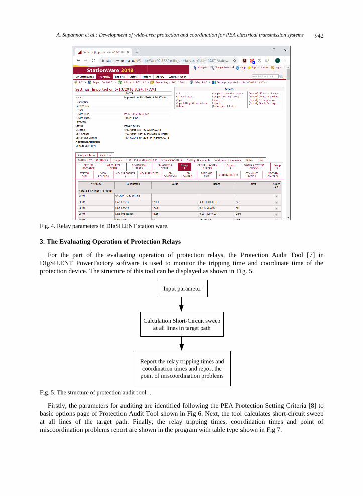
Fig. 4. Relay parameters in DIgSILENT station ware.
3. The Evaluating Operation of Protection Relays
For the part of the evaluating operation of protection relays, the Protection Audit Tool [7] in
DIgSILENT PowerFactory software is used to monitor the tripping time and coordinate time of the
protection device. The structure of this tool can be displayed as shown in Fig. 5.
Input parameter
Calculation Short-Circuit sweep
at all lines in target path
Report the relay tripping times and
coordination times and report the
point of miscoordination problems
Fig. 5. The structure of protection audit tool .
Firstly, the parameters for auditing are identified following the PEA Protection Setting Criteria [8] to
basic options page of Protection Audit Tool shown in Fig 6. Next, the tool calculates short-circuit sweep
at all lines of the target path. Finally, the relay tripping times, coordination times and point of
miscoordination problems report are shown in the program with table type shown in Fig 7.
942.: Development of wide-area protection and coordination for PEA electrical transmission systems A. Supannon et al

Fig. 6. Basic options page of Protection Audit Tool.
Fig. 7. The Protection Audit Report.
4. The Reconfiguration of Miscoordinated Relays Settings
For the part of the reconfiguration of miscoordinated relays settings, the tool for reconfiguration of
miscoordinated relays settings was developed by programming DIgSILENT Programming Language
(DPL) script [9] in PowerFactory software.
The flowchart of the purposed tool is illustrated in Fig. 8. Firstly, the users must input the parameters
such as the relay setting criteria (tripping time of each zone, reach of each zone, etc.) and the protection
boundary. The users need to select the path of transmission systems within protection zones to input the
protection boundary. Then, the program will check the setting of measurement unit of the relays. If the
measurement unit of relays have not been set, the program will calculate new setting parameters. Next
step, the program will calculate the impedance for settings in each protection zone. Then, the program
calculates the settings for initial zone by run single-phase to-ground short circuit sweep to collect the
minimum fault current (at the boundary of the zone) through acceptable fault resistance in the zone. If the
943 International Journal of Smart Grid and Clean Energy, vol. 9 , no. 6, November 2020

impedance of ground relay is set to comply with the relay setting criteria, calculate 3-phase short circuit
sweep to recheck the settings. Unless the settings of ground and phase of each zone are related, the
program will improve the setting again. The relay settings of other zones will repeat the same process.
Finally, if the settings are set to comply with the criteria, the program will export the results for
completed settings to the user.
Start
Input Parameter
- Relay Settings Criteria
- Protection Boundary (select path of transmission
and distribution systems within protection zones)
Checking the Settings of
measurement units of relay
- Polarizing
- Starting
Calculate new settings of
measurement units
Calculate the impedance
for settings in each
protection zones
Set initial zone
of protection
Calculation short circuit to
check relay coordination
Checking the
operation of relay
All zone coordinated?
Improve the
setting of relays
Change Zone
Show result to output
window
Fail
True
Fail
True
No
Yes
end
Fig. 8. The flowchart of the purposed tool.
5. Case Study and Results
The case study in this paper is shown in Fig. 9. A transmission system of the PEA southern 1 region is
used as case study. The source of this system is from RB2_EGAT substation by Electricity Generating
Authority of Thailand (EGAT) that delivers the power through Ratchaburi 2 (RBB) substation to
Photharam (PTR) substation, Damnoen Saduak (DNA) substation and Pak Tho (PTH) substation. In this
case, a DG is located at Ratchaburi 3 (RBCx) temporary substation, which connected to tap-line between
944.: Development of wide-area protection and coordination for PEA electrical transmission systems A. Supannon et al

RBB and PTR substation. Fig. 10 shows the relays data of each substation in DIgSILENT StationWare.
RB2_EGAT
RBB
PTR
DNA
PTH
Fig. 9. A transmission system of the PEA southern 1 region.
Fig. 10. The relays data of each substation in DIgSILENT StationWare.
The relay data in DIgSILENT StationWare was imported to DIgSILENT PowerFactory via DPL
scripts named “PSMSExport” and “PSMSImport”. The Mapping Table file (MappingTable.xlsx) is
responsible for specifying the relay parameters to be imported. The structure of the interface between
945 International Journal of Smart Grid and Clean Energy, vol. 9 , no. 6, November 2020

PowerFactory and StationWare is shown in Fig. 11.
Fig. 11. The structure of the interface between PowerFactory and StationWare.
The Protection Audit Tool is used for evaluating operation of protection relays. The parameters for
auditing are identified following the PEA Protection Setting Criteria to Protection Audit Tool. Table 1
shows an important parameter using in Protection Audit Tool. Fig. 12 shows the relay coordination
results by using Protection Audit Tool.
Table 1. Important parameter using in protection audit tool
Parameter Value
Time of Zone 1 0 s
Time of Zone 2 0.3 s
Time of Zone 3 0.6 s
Time of Zone 4 0.6 s
Percent Impedance of Line
Zone 1 85% of line section I
Percent Impedance of Line Zone 2
100% of line section I + 50% of line section II
Percent Impedance of Line
Zone 3
100% of line section I
+ 120% of line section II
Percent Impedance of Line Zone 4
15% of line section I (Reverse Zone)
Fig. 12. The relay coordination results by using protection audit tool.
The result in Fig. 12 shows the case of primary relay miscoordination is 8.65% and secondary relay
miscoordination is 7.69%. Most miscoordination case are caused by the relay underreach with DG effect.
The DG acts to support the network voltage, so it causes the increasing of the impedance to the fault seen
by the relay. Then the relay will calculate that the fault is further away, outside the zone of protection and
so it will not operate.
The reconfiguration of miscoordinated relays settings tool by DPL scripts is applied to transmission
system of the PEA southern 1 region. Some constant parameters used in the simulations are shown in
Table 1. These constant parameters were entered to DPL command window shown in Fig.13. The relay
coordination results after using the reconfiguration of miscoordinated relays settings is shown in Fig. 14.
946.: Development of wide-area protection and coordination for PEA electrical transmission systems A. Supannon et al

Fig. 13. The DPL command window.
Fig. 14. The relay coordination results after using the reconfiguration of miscoordinated relays settings.
The result in Fig. 14 shows the relay coordination results after the adjustment of relay settings by
developed tool. The case of primary relay miscoordination was decreased to 1.15% and secondary relay
miscoordination was decreased to 0.58%. The miscoordination cases are the cases where the
miscoordination cannot be solved because of system topology or constraints in the protection
technologies installed.
6. Conclusion
The methodology of development WAPC for PEA electrical transmission systems has been presented
in this paper. The methodology of development WAPC consists of three main parts: the database
management system, the evaluated operation of relays and the reconfiguration of miscoordinated relays.
DIgSILENT Stationware software is used as a database management software and DIgSILENT
PowerFactory is used as an analysis software. This proposed method could be used to solve
miscoordinated relays and to manage data. The results show that can lead the transmission to be more
947 International Journal of Smart Grid and Clean Energy, vol. 9 , no. 6, November 2020

reliability by improving selectivity of the protection and therefore limiting the outage area. Even though,
there are some cases that cannot be solved regarding the complex of system topology or the limitations in
the established protection elements. The outcomes of this study can be used by system engineers as well
as researchers for operating protection systems. The future research will be focused on the possible
protective levels related to this class of protection coordination.
Conflict of Interest
Currently, PEA is responsible for distributing electricity to various areas of Thailand. PEA primary
business operations are focused on supplying electrical power and providing electrical power services.
PEA is a leading electrical power service provider that has transmission and distribution systems covering
of all areas in Thailand. Therefore, the author declares that in this paper no conflict of interest.
Author Contributions
In order to qualify for authorship, all authors have engaged in research and preparation as follows. This
study was designed, directed, and coordinated as the principal inspectors, providing conceptual and
technical advice for all aspects of this project by Assoc. Prof. Dr. Suttichai Premrudeepreechacharn.
performed and supported the experimental data by PEA as Narong Tantichayakorn. Commented by Asst.
Prof. Dr. Piyadanai Pachanapan. Finally, summary and wrote the paper by Autthaporn Supannon.
Acknowledgements
The authors would like to thank PEA for technical support and Graduate School and Faculty of
Engineering, Chiang Mai University for financial support.
References
[1] Pérez CP, Castillo I, Martin J. Protection coordination in the transmission system and boundaries–A wide area coordination
study. In: Western Protective Relay Conference, 2017:1–9.
[2] Barman B, Clack J, Padaca V. A practical guide to performing wide-area coordination analysis. In: Western Protective Relay
Conference, 2014:1–11.
[3] Chen M, Wang H, Shen S, He B. Research on a distance relay-based wide-area backup protection algorithm for transmission
lines. IEEE Trans. Power Delivery, 2017; 32(1):97-105.
[4] Maneerat P, Premrudeepreechacharn S, Supannon A. Development of wide area protection & coordination for PEA’s 115 kV
closed loop transmission lines in chiang mai area. In: 2018 53rd International Universities Power Engineering Conference
(UPEC), 2018:1–6.
[5] DIgSILENT GmbH. DIgSILENT StationWare 2018 User Manual. Gomaringen, Germany; 2018.
[6] Bangert D, Hoffmann U. (November 2016). Implementation of a Protection Settings Database for Managing Protective Device
Settings at the 50Hertz Transmission GmbH. [Online]. Available: http://www.digsilent.de/en/downloads.
[7] DIgSILENT GmbH. DIgSILENT PowerFactory 2018 User Manual. Gomaringen, Germany; 2018.
[8] Power System Protection Division of PEA. Criteria Setting of Distance Relays for Provincial Electricity Authority. Bangkok,
Thailand; 2016.
[9] DIgSILENT GmbH. DIgSILENT PowerFactory Advance Tutorial DIgSILENT Programming Language (DPL). Gomaringen,
Germany; 2017.
Copyright © 2020 by the authors. This is an open access article distributed under the Creative Commons Attribution License (CC
BY-NC-ND 4.0), which permits use, distribution and reproduction in any medium, provided that the article is properly cited, the use
is non-commercial and no modifications or adaptations are made.
948.: Development of wide-area protection and coordination for PEA electrical transmission systems A. Supannon et al