development trends in high -power free -electron … trends in high -power free -electron lasers...
TRANSCRIPT

Development TrendsDevelopment Trends
in Highin High--PowerPower
FreeFree--Electron LasersElectron Lasers
Yehoshua SocolYehoshua Socol
07.12.201107.12.2011

AcknowledgementsAcknowledgements
C. C. BrauBrau Vanderbilt Vanderbilt UUSSD. DouglasD. Douglas JLabJLab USUSB. B. MilitsynMilitsyn ASTeCASTeC UKUKD. D. RatnerRatner SLACSLAC USUSN. N. VinokurovVinokurov BINPBINP RussiaRussiaR. R. WWüünschnsch FZDFZD GermanyGermany
H. Bluem, A. ToddH. Bluem, A. ToddAdvanced Energy Systems, Inc.Advanced Energy Systems, Inc.
C. C. PielPiel RI Research Instruments GmbHRI Research Instruments GmbHB. van B. van derder GeerGeer Pulsar PhysicsPulsar PhysicsJ. J. ShwartzShwartz Northrop Grumman (ret.)Northrop Grumman (ret.)

ContentsContents
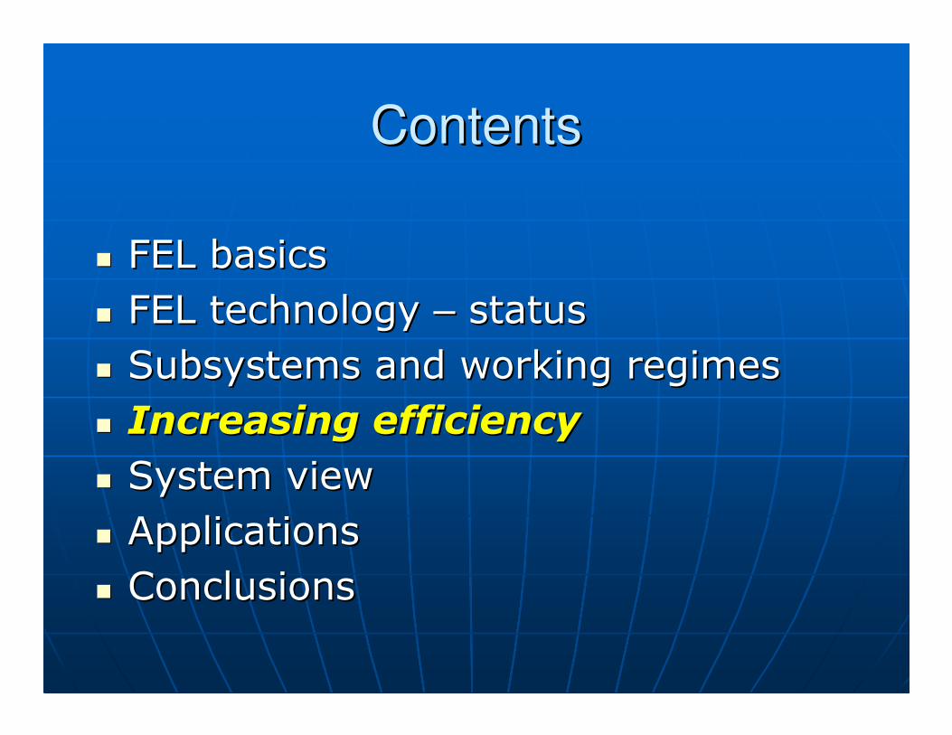
FEL basicsFEL basics FEL technology FEL technology –– statusstatus Subsystems and working regimesSubsystems and working regimes Increasing efficiency Increasing efficiency System viewSystem view ApplicationsApplications ConclusionsConclusions

Though called Though called ““laserlaser””, FEL is , FEL is essentially a big electronessentially a big electron--beam beam vacuum tubevacuum tube
Though optical or even hard XThough optical or even hard X--ray ray radiation is emitted, the FEL is fully radiation is emitted, the FEL is fully described by classical described by classical electrodynamics & mechanics electrodynamics & mechanics (relativistic)(relativistic)

FEL FEL –– operation principleoperation principle

FEL wavelengthFEL wavelength
λ= λw (c – v) / v
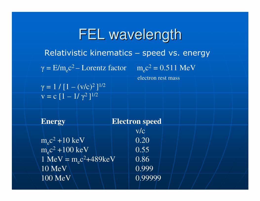
FEL wavelengthFEL wavelengthRelativistic kinematics – speed vs. energy
γ = E/mec2 – Lorentz factor mec
2 = 0.511 MeV
electron rest mass
γ = 1 / [1 – (v/c)2 ]1/2
v = c [1 – 1/ γ2 ]1/2
Energy Electron speed
v/c
mec2 +10 keV 0.20
mec2 +100 keV 0.55
1 MeV = mec2+489keV 0.86
10 MeV 0.999
100 MeV 0.99999

FEL wavelengthFEL wavelength
λ = k λW / 2γ 2
λ IR wavelength
λW undulator period
γ Lorentz-factor
γ = E/mec2
k ~ 1-2sometimes higher (LCLS)
λ = 1-10 µm
λW= 2 cm
E(beam) = 15-50 MeV mec2 = 0.511 MeV
0 5 10 15 20 25 30 35 40 45 500
2
4
6
8
10
12
E[MeV]
λ[ µ
m]

FEL FEL –– operation principleoperation principle
Vanderbilt University aVanderbilt University animationnimationhtm.fel_works/fel/flash/multimedia/exploration/edu.vanderbilt.www://http
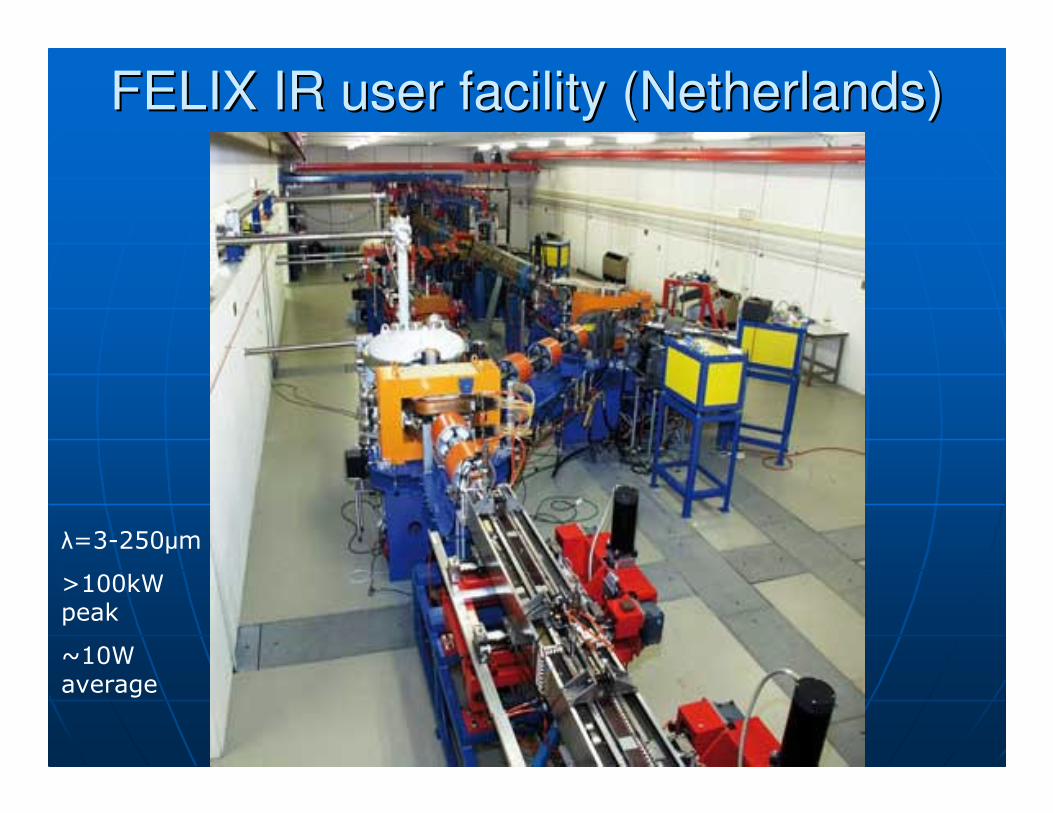
FELIX IR user facility (Netherlands)FELIX IR user facility (Netherlands)
λ=3-250µm
>100kW peak
~10W average
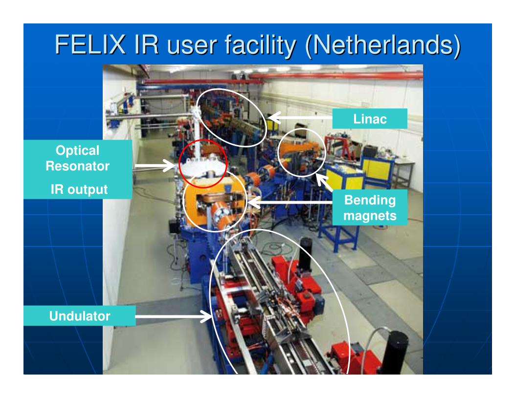
Linac
Bending magnets
Optical Resonator
IR output
Undulator
FELIX IR user facility (Netherlands)FELIX IR user facility (Netherlands)

FEL AdvantagesFEL Advantages
TunabilityTunability 10 GHz 10 GHz -- 11ÅÅ
Excellent beam quality Excellent beam quality MM22<1.1<1.1
High peak power (10+ MW)High peak power (10+ MW) AllAll--electricelectric
ChallengesChallenges No industrial experienceNo industrial experience Low efficiencyLow efficiency aim: 10%aim: 10%
Ionizing radiationIonizing radiation Size, costSize, cost

FEL spectral coverageFEL spectral coverage
FEL technology:FEL technology: XX--band (10 GHz) =>band (10 GHz) =>XX--rays (1 rays (1 ÅÅ=0.1nm)=0.1nm)
Single FEL machine:Single FEL machine: ~ 1.5~ 1.5--2 decades of 2 decades of λλ(with 2(with 2--3 3 undulatorsundulators))
Areas of interest Areas of interest
X to VUVX to VUV 0.1 0.1 --200 nm200 nmMidMid-- to farto far--IRIR 1.51.5--1000 1000 µµmm

FEL powerFEL power
micropulse (20 micropulse (20 psps)) 11--10+ 10+ MWMW MACROpulseMACROpulse ((10 10 µµs)s) 100100--500 kW500 kW AverageAverage 0.10.1--100 kW100 kW

ContentsContents
FEL basicsFEL basics FEL technology FEL technology –– statusstatus
Subsystems and working regimesSubsystems and working regimes Increasing efficiency Increasing efficiency System viewSystem view ApplicationsApplications ConclusionsConclusions

FEL maturity FEL maturity –– signssigns
New FEL user centers New FEL user centers ScaleScale--up up ××40 in 2009 (SLAC)40 in 2009 (SLAC) First commerciallyFirst commercially--built built ee--beamlinebeamline US Navy US Navy --> industry (Boeing)> industry (Boeing)

Operating Operating FELsFELs –– for Scientific Researchfor Scientific Research
X/UV FEL facilitiesX/UV FEL facilities
1.1. LCLS LCLS –– SLACSLAC USUS2.2. FLASH FLASH –– DESY DESY GermanyGermany3.3. European UV/VUV FEL at European UV/VUV FEL at ElettraElettra ItalyItaly4.4. Duke University FEL Laboratory Duke University FEL Laboratory USUS
IR FEL FacilitiesIR FEL Facilities
1.1. Jefferson Lab Jefferson Lab USUS2.2. FELBE FELBE –– FZD FZD GermanyGermany3.3. FELIX FELIX –– FOM FOM NetherlandsNetherlands4.4. CLIO CLIO –– LCP (LCP (OrsayOrsay)) FranceFrance5.5. AIST/AIST/Kawasaki Kawasaki Japan Japan 6.6. BudkerBudker Institute (BINP) Institute (BINP) RussiaRussia

FEL research facilities FEL research facilities –– in constructionin construction
X/UVX/UV
1.1. SCSS SCSS –– SPringSPring--88 JJapanapan2.2. European XFEL European XFEL GermanyGermany3.3. Swiss FEL Swiss FEL –– PSIPSI SwitzerlandSwitzerland4.4. MAXMAX--IVIV SwedenSweden5.5. FERMI@ FERMI@ ElettraElettra ItalyItaly
IRIR
1.1. Fritz Fritz HaberHaber Institute (FHI)Institute (FHI) GGermanyermany2.2. FLARE FLARE –– RadboudRadboud University University NetherlandsNetherlands3.3. ALICE ALICE –– DaresburyDaresbury UKUK

FLARE THz FELFLARE THz FEL
FLARE – Radboud University, Nijmegen, Netherlands Wavelength: 0.1-1.5 mm
Courtesy

ScaleScale--up: LCLS (2009)up: LCLS (2009)
RecordRecord--short wavelength:short wavelength:FLASH (DESY)FLASH (DESY) LCLSLCLS
λλ ==6.5 nm 6.5 nm => => 0.15 nm0.15 nm
EEphotonphoton=0.2 =0.2 keVkeV =>=> 8 8 keVkeV
ScaleScale--up up ××40 in one blow40 in one blow
FEL technology is FEL technology is
well understood!well understood!

LCLS at SLACLCLS at SLAC
1 km
SLAC 3 km

IRIR--THz FELTHz FELat Fritz at Fritz HaberHaber Inst (Berlin)Inst (Berlin)
Putting Accelerator Technology to Work
Wavelength: 4-500 µmP(peak)~10 MWP(av)~10 W
In commissioning
Turn-key e-beamlime

FEL Progress 1990FEL Progress 1990--20102010
ConsiderableConsiderableFEL interactionFEL interaction
MajorMajorAccelerationAcceleration
ConsiderableConsiderableInjectionInjection
ProgressProgressSubSub--systemsystem
Reliability up RF sources e-beam control
Cost down energy-recovery multi-turn accelerating RF sourcescontrol hardware

ContentsContents
FEL basicsFEL basics FEL technology FEL technology –– statusstatus Subsystems and working regimesSubsystems and working regimes
Increasing efficiency Increasing efficiency System viewSystem view ApplicationsApplications ConclusionsConclusions

RF source
Accelerator -recuperator
Undulator30 - 100
MeV
1-5
MeV IR out
FEL SubsystemsFEL Subsystems
Injector
IR Optics

Electron acceleration system:Electron acceleration system:
RFRF--linaclinac
To undulator
Injector Accelerator

RFRF--linaclinac pulse structurepulse structureall numbers all numbers –– for illustration onlyfor illustration only
S-band ~ 3 GHz
40-100 Hz Rep. rate
micropulse
MACROpulse
10 µs

FEL single-pass gain (G)
G = [ P(out) / P(in) ]SINGLE PASS
•• Low gain G ~ 20Low gain G ~ 20--30%30%
•• High (exponential) gain High (exponential) gain G > 10G > 1033
FEL gain regimesFEL gain regimes

FEL FEL –– operation modesoperation modes
OscillatorOscillator•• LowLow--gain gain ~20% per pass~20% per pass
•• HighHigh--gain gain ~10~1033 per passper pass
Regenerative Amplifier FEL Regenerative Amplifier FEL -- RAFELRAFEL
AmplifierAmplifier•• SeededSeeded•• SelfSelf--amplified spontaneous emission amplified spontaneous emission
SASESASE

ee--beam & optical pulsesbeam & optical pulsesoscillator / RAFELoscillator / RAFEL
e-beam pulses
optical pulses
Mirrors – optical resonator

FEL FEL –– output power output power
P(IR) ~ η × P(e-beam)
P(e-beam) = I U ≈ I E/e
E – e-beam energy
U=50MeV, I=1A =>P(e-beam) =50 MW (!)

FEL FEL –– extraction efficiency extraction efficiency η
LowLow--gain regime: gain regime: oscillatoroscillator
P(IR) ≈≈ P(e-beam) / 2N/ 2Nww
η ≈≈ 1/2N/2Nww ~ 2-3%
HighHigh--gain regime: gain regime: amplifier or amplifier or ““Regenerative AmplifierRegenerative Amplifier””
P(IR) ≈≈ P(e-beam) ×× ρρ ((ρρ –– ““Pierce parameterPierce parameter””))
η ≈≈ ρρ <1%gain E0
E0/2Nw
ContentsContents
FEL basicsFEL basics FEL technology FEL technology –– statusstatus Subsystems and working regimesSubsystems and working regimes Increasing efficiencyIncreasing efficiency
System viewSystem view ApplicationsApplications ConclusionsConclusions

Goal: 10%
P(IR) ~ η×P(e-beam)
η ~ 2-3% for oscillator
<1% for amplifier
Challenges:
1. Low extraction efficiency
(e-beam to optical energy)
2. High RF losses in accelerator
(cavity load)
WallWall--plug efficiencyplug efficiency
gain E0
E0/2Nw
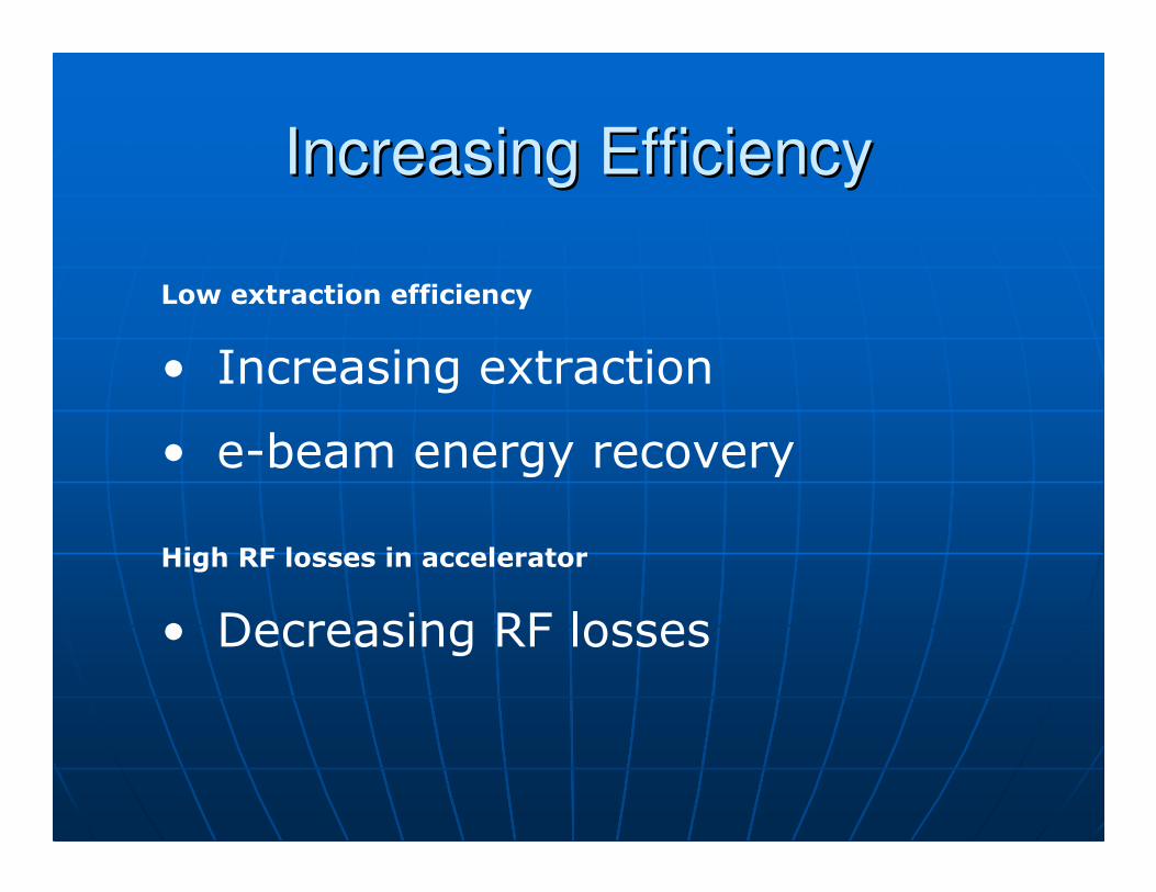
Low extraction efficiency
• Increasing extraction
• e-beam energy recovery
High RF losses in accelerator
• Decreasing RF losses
Increasing EfficiencyIncreasing Efficiency

1. Increasing extraction:1. Increasing extraction:
Tapered undulatorTapered undulatorgain E0
E0/2Nw
E-beam
Tapering effective for
Amplifier η ~ 2-3%Oscillator η ~ 3-4%external seed or internal etalon
: worse energy recoveryhigher e-beam energy spread

2. e2. e--beam Energy Recoverybeam Energy RecoveryERLERL –– Energy Recovery Energy Recovery LinacLinac
20% RF20% RF--toto--IR efficiencyIR efficiency<= 2% extraction + 90% recovery<= 2% extraction + 90% recovery
50% DC50% DC--toto--RF conversion =>RF conversion =>
Overall efficiency ~10%Overall efficiency ~10%
ERL FEL at Jefferson Lab (US)

3. Decreasing RF losses3. Decreasing RF losses
RF power = eRF power = e--beam load beam load + Cavity Load (CL) + Cavity Load (CL) => loss=> loss
CL CL =|E|=|E|2 2 L / L / ρρ = U= U22/R /R R = R = ρρ LL
ρρ ~ 5~ 5--10 M10 MΩΩ/m at 180 MHz/m at 180 MHzρρ ~ 50~ 50--65 M65 MΩΩ/m at 3 GHz (S/m at 3 GHz (S--band)band)SS--band: E=50MeV L=2m => band: E=50MeV L=2m =>
CL = 20 MW (!)CL = 20 MW (!)
w/o current !w/o current !
SolutionsSolutionsA.A. Superconducting cavitiesSuperconducting cavitiesB.B. MultiMulti--turn acceleration/recoveryturn acceleration/recovery

A. SRF A. SRF –– superconducting RF superconducting RF linaclinac
DrawbacksDrawbacks Higher cost Higher cost (may be (may be ××10)10)
Power for Power for cryocryo--cooling cooling (~50kW CW for 10MeV)(~50kW CW for 10MeV)
Bulky, low robustnessBulky, low robustness
JAEA 1kW FEL (Japan)

B. B. ““WarmWarm”” multimulti--turn turn
EnergyEnergy--Recovery Recovery LinacLinac (ERL)(ERL)
Cavity load (CL) = UCavity load (CL) = U22/R/R22--turn ERL: 75% decrease in CLturn ERL: 75% decrease in CLUU22=U=U11/2 =>/2 =>CLCL22 = CL= CL11/4/4
CLCL3 3 = CL= CL11/9/9
CLCL4 4 = CL= CL11/16/16

MultiMulti--turn turn
EnergyEnergy--Recovery Recovery LinacLinac (ERL)(ERL)
AdvantagesAdvantages Reduced sizeReduced size Reduced RF powerReduced RF power Reduced costReduced cost
ProblemProblemComplicatedComplicatedee--beam opticsbeam optics

HF resonators (accelerating cavities)
Old THz undulator
New optical resonator
New undulator
Budker Institute of Nuclear Physics, RussiaCourtesy Prof. Vinokurov N.A.
WorldWorld--first multifirst multi--turn ERL FELturn ERL FEL
λ=40-240µm
>100kW peak
~0.5 kW average

MultiMulti--turn turn separateseparate--tracktrack ERL FELERL FEL
Injector
RF2
Dump
RF1
Undulator / Resonator
Booster
Y. Socol et al. Phys. Rev. Spec. Topics – Accelerators & Beams 2011with Budker INP (Russia)
Helmholtz Zentrum Berlin

ContentsContents
FEL basicsFEL basics FEL technology FEL technology –– statusstatus Subsystems and working regimesSubsystems and working regimes Increasing efficiency Increasing efficiency System viewSystem view
ApplicationsApplications ConclusionsConclusions

RF source
Accelerator -recuperator
Undulator30 - 100
MeV
1-5
MeV IR out
FEL SubsystemsFEL Subsystems
Injector
IR Optics

RF source
Accelerator -recuperator
Undulator30 - 100
MeV
1-5
MeV IR out
““BottlenecksBottlenecks”” for highfor high--power FELpower FEL
Injector
IR Optics

Injector Injector •• High pulse current ( >25 A)High pulse current ( >25 A)•• Low energy spread (Low energy spread (rmsrms<0.5%)<0.5%)
•• Medical/industrial eMedical/industrial e--beams: beams: rmsrms ~ 5~ 5--10%10%
•• Low angular spread (Low angular spread (∆θ∆θ ∆∆rr << << λλ))
IR OpticsIR Optics•• High power density ( > 10 MW / cmHigh power density ( > 10 MW / cm22))•• Presence of ionizing radiationPresence of ionizing radiation
““BottlenecksBottlenecks”” for highfor high--power FELpower FEL

Why injector ?Why injector ?
•• SpaceSpace--charge echarge e--beam spreadbeam spread•• ““EmittanceEmittance growthgrowth”” ––
ee--beam quality downbeam quality down
Important at low energiesImportant at low energies
V1 < V2

Why injector ?Why injector ?
SpaceSpace--charge: low energiescharge: low energies
0 0.2 0.4 0.6 0.8 1 1.2 1.4 1.6 1.8 20
20
40
60
80
100
120
140
160
180
200
Accelerating Voltage, MeV
Radiu
s s
pre
ad,
%
Space-charge beam spread - free propagation
L=0.1m J=1A/mm2

Injector => cathodeInjector => cathode
ThermionicThermionic cathodecathode•• Limited currentLimited current•• Limited eLimited e--beam qualitybeam quality
acceptable for IRacceptable for IR--FELFEL
PhotoPhoto--cathodecathode•• Low working time (~ hours)Low working time (~ hours)•• Low standLow stand--by time (days to weeks)by time (days to weeks)•• Size, complexity, cost (~M$)Size, complexity, cost (~M$)

LosLos--Alamos photoAlamos photo--cathode guncathode gun
2003
2008

IR Optics IR Optics –– power handlingpower handling
Problem: high flux + ionizing radiationProblem: high flux + ionizing radiation
Anticipated solutionsAnticipated solutions
BeamBeam--expanding at grazing incidenceexpanding at grazing incidence
D. Dowell, IEEE J. Quant. D. Dowell, IEEE J. Quant. ElectrElectr. 1991. 1991
Metal mirrors or gratings Metal mirrors or gratings

System: power-gain trade-offSystem: powerSystem: power--gain tradegain trade--offoff
30 32 34 36 38 40 42 44 46 48 500
5
10
15
20
25
30
35
Gain
IR Power
Gain
,%
Avera
ge P
ow
er,
a.u
.
Undulator length, a.u.

More system problemsMore system problems(partial list)(partial list)
Vibrations Vibrations •• Optical resonatorOptical resonator•• RFRF--linaclinac•• Liquid helium (for Liquid helium (for cryocryo--systems)systems)
Ionizing radiationIonizing radiation

Ionizing radiation problemIonizing radiation problem
P(IR)=1MWP(IR)=1MWI=1A (E=50MeVI=1A (E=50MeV η=2%)=2%)Interception 10Interception 10--4 4 => => I(effI(eff)=0.1 )=0.1 mAmAD=DD=D’’ I(eff)t/LI(eff)t/L22
DD’’(50MeV)~10(50MeV)~105 5 R mR m22/A s/A s
•• t = 10 st = 10 s•• L= 10 m L= 10 m –– distance to crew membersdistance to crew members
D (pulse) = 1 RD (pulse) = 1 RD (permit) = 5 R/year!D (permit) = 5 R/year!
typical shielding: 10typical shielding: 10--20 cm Fe (20 cm Fe (PbPb))
10001000--2000 kg/m2000 kg/m22

Radiation risk in perspectiveRadiation risk in perspective
350 R350 R exposure: LDexposure: LD50 50 (if no treatment)(if no treatment) 100 R100 R
First signs of radiation illness First signs of radiation illness ––vomiting, fatigue, nauseavomiting, fatigue, nausea
Life expectancy 82 Life expectancy 82 --> 81.5 years> 81.5 years 10 R10 R
Life expectancy 82 Life expectancy 82 --> 81.95 (may be)> 81.95 (may be)

Radiation Radiation –– curious factscurious facts
II’’m radioactive;m radioactive;YouYou’’re too!re too!•• 1414C is present in air, plants & all livingC is present in air, plants & all living
US FDA: nonUS FDA: non--radioactive spirits radioactive spirits ––not suitable for human consumption!not suitable for human consumption!

ContentsContents
FEL basicsFEL basics FEL technology FEL technology –– statusstatus Subsystems and working regimesSubsystems and working regimes Increasing efficiency Increasing efficiency System viewSystem view ApplicationsApplications
ConclusionsConclusions
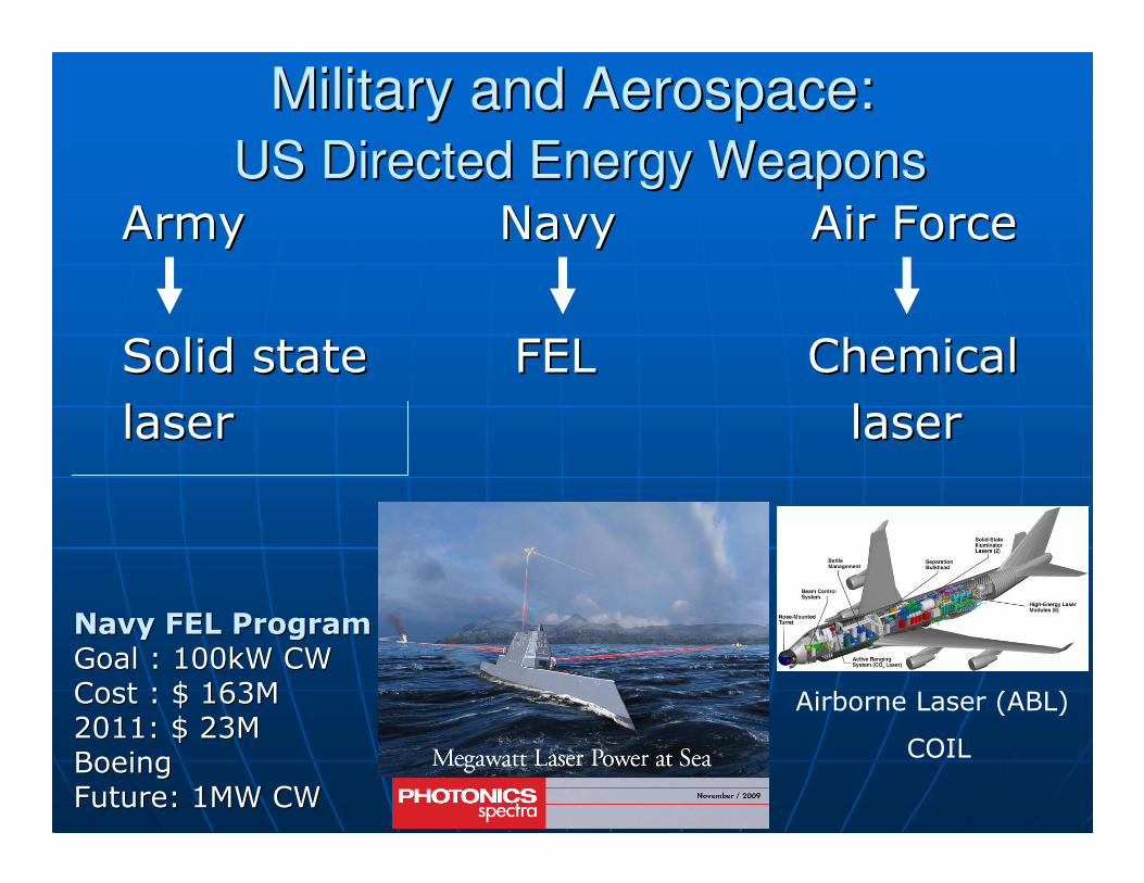
Military and Aerospace:Military and Aerospace:
US Directed Energy WeaponsUS Directed Energy Weapons
ArmyArmy NavyNavy Air ForceAir Force
Solid state FEL ChemicalSolid state FEL Chemicallaser laser laserlaser
Navy FEL ProgramNavy FEL Program
Goal : 100kW CWGoal : 100kW CWCost : $ 163MCost : $ 163M2011: $ 23M2011: $ 23MBoeingBoeingFuture: 1MW CWFuture: 1MW CW
Airborne Laser (ABL)
COIL

Thomas Jefferson National
Accelerator Facility
Year 2004 2006
Power (average), kW 10 14.2
Wavelength, µm 6.0 1.6
Duration, s ~20 ~30
Achieved once once
US Navy FEL ProgramUS Navy FEL Program

US Navy FEL ProgramUS Navy FEL Program
Goal: 100kW CW (lab prototype)Goal: 100kW CW (lab prototype)Cost: $ 163MCost: $ 163M20092009--2010: 2010: 2 x 7 M$ 2 x 7 M$
to Boeing & Raytheonto Boeing & Raytheon2011: 2011: $ 23M $ 23M
to Boeing (design only)to Boeing (design only)
Final goal: 1MW CWFinal goal: 1MW CW

13.513.5--nm FEL for EUV lithographynm FEL for EUV lithography
Injector
RF2
Dump
RF1
Undulator / Resonator
Booster
40 m
Y. Socol et al. Phys. Rev. ST Accel. Beams 14, 040702 (2011).
with Budker INP (Russia)
Helmholtz Zentrum Berlin
PhotoPhoto--chemistrychemistry
•• Surface treatmentSurface treatment•• NanotubeNanotube synthesissynthesis•• Isotope separationIsotope separation•• ??
FEL advantagesFEL advantages
Tuned photons in IRTuned photons in IR--UVUV 22--photon reactionsphoton reactions UltraUltra--short (<1ps) pulsesshort (<1ps) pulses

Anticipated trends Anticipated trends –– highhigh--powerpower““It is difficult to make predictions, especially about the futureIt is difficult to make predictions, especially about the future””
Mark Twain ?Mark Twain ?
Warm (normalWarm (normal--conducting) conducting) acceleratorsaccelerators
ThermionicThermionic cathodescathodes

ConclusionsConclusions
FEL FEL –– unique tunable allunique tunable all--electric laserelectric laser
Breakthrough 2009Breakthrough 2009--10: 10: 1) technological maturity proven1) technological maturity proven2) multi2) multi--turn scheme =>turn scheme =>
reduced size, weight, costreduced size, weight, cost
Further progress anticipatedFurther progress anticipated