device, electronic, technology to allow the …
TRANSCRIPT

EXTRACTION OF A VACUUM ENERGY CONFORMING TO EMMY NOETHER'S THEOREM: 29/09/2021 Dr SANGOUARD Patrick
1
DEVICE, ELECTRONIC, TECHNOLOGY TO ALLOW THE
EXTRACTION OF VACUUM ENERGY
SANGOUARD Patrick:
EXTRACTION OF A VACUUM ENERGY CONFORMING TO EMMY NOETHER'S THEOREM OF 1915 ?:
principle, mathematization, simulation, electronics, and technology
. Tel: 06 86 50 78 44
EXTRACTION OF A VACUUM ENERGY CONFORMING TO EMMY NOETHER'S THEOREM: 29/09/2021 Dr SANGOUARD Patrick
2 TABLE OF CONTENTS
I / OBTAINING AN ELECTRIC CURRENT FROM VACUUM?
I.1 / Introduction
I.2 / Brief presentation of Casimir's force
I.3 / extract energy from a vacuum?
II / DESCRIPTION OF THE PRINCIPLE USED TO "EXTRACT" ENERGY FROM THE VACUUM
III / CALCULATION OF THE CURRENT GENERATED BY THE CASIMIR STRUCTURE
III.1 / calculation of the vibration frequency of the casimir structure
III .2 / Calculation of the current peak
IV / USE OF DIFFERENT PIEZOELECTRIC MATERIALS
IV.1 = PIEZOELECTRIC MATERIAL = PZT
IV-1.1 / Space between Casimir electrodes as a function of time over 2 periods, for different trigger
values of MOS transistors
IV-1.2 / Spatial and temporal evolution of the Coulomb and Casimir forces during an entire period
IV-1-3 / Variation of the starting interface z0 between Casimir electrodes: PZT
IV-1-4 / variation of the length ls of the Casimir electrode: PZT
IV-1-5 / variation of the width bp of the piezoelectric bridge: PZT
IV-1-6 / variation of the thickness ap of the piezoelectric bridge: PZT
IV-1-7 / variation of the proportionality ratio p = FCO / FCA: PZT
IV-2 / USE OF OTHER PIEZOELECTRIC MATERIALS
IV-2-1 / Piezoelectric material = PMN-PT
IV-2-1-1 / Evolution of the Casimir interface as a function of time during two periods
IV-2-1-2 / Evolution of the forces of Casimir and Coulomb
IV-2-1-3 / Ratio variation as a function of Casimir interval and current peak as a function of
the ratio: PMN-PT
IV-2-1-4 / peak current as a function of time and peak voltage at the
terminals of the choke for 2 periods: PMN-PT
IV-2-1-5 / threshold voltage according to the desired FCO / FCA ratio
IV-2-1-6 / Vibration frequency as a function of the FCO / FCA ratio and peak current as a
function of the Casimir interval chosen: PMN-PT
IV-2-2 / Piezoelectric material = AlN
IV-3 / CONCLUSIONS
V / TRANSFORMATION AND AMPLIFICATION ELECTRONICS WITHOUT EXTERNAL SUPPLY OF A
PERIODIC SIGNAL OF A FEW MILLIVOLTS IN A CONTINUOUS VOLTAGE OF A FEW VOLTS
VI / EMBODIMENT TECHNOLOGY OF THE CURRENT EXTRACTOR DEVICE USING THE FORCES
OF CASIMIR IN A VACUUM
VII / STEPS FOR THE REALIZATION OF THE STRUCTURE AND ITS ELECTRONICS
VIII / ENERGY BALANCE
IX / CONCLUSIONS BIBLIOGRAPHY APPENDICES
X / A FEW REMINDERS FROM RDM
X.1 / Calculation of the deflection of a bridge embedded at its 2 ends X.2 /
Calculation of the resonant frequency of the piezoelectric bridge
X.2.1 / Differential equation of a vibrating beam and determination of the eigen modes
X.2.2 / Eigen modes and frequencies
X.2.3 / Boundary conditions:
XI / MATLAB PROGRAM USED FOR NUMERICAL SIMULATION
EXTRACTION OF A VACUUM ENERGY CONFORMING TO EMMY NOETHER'S THEOREM: 29/09/2021 Dr SANGOUARD Patrick
3 LIST OF FIGURES
Figure 1: Casimir effect
Figure 2: General representation of the structure
Figure 3: View of the device without electronics
Figure 4: Different view of the device without electronics
Figure 4b: Representation of the reference used Axes, Forces, Electrodes Casimir
Figures 5: general configuration of the device: MOS grid connections (Face 2 of the piezoelectric bridge: red),
Source connections (Face 1 of the piezoelectric bridge: green)
Figure 6: distribution of the threshold voltages of the enriched and depleted N and P MOS switches
Figure 7: Polarization, applied force and appearing load on a piezoelectric block
Figure 7b: Piezoelectric coupling mode
Figure 8: Figure 8: Piezoelectric bridge Cutting Reactions and Bending Moment, Deflection Angle
Figure 9: Table of characteristics used for MATLAB and ANSYS simulations
Figure 10: Final structure with the metal oxides surrounding the metal electrodes
Figure 11: Interval between Casimir electrodes as a function of time for a proportionality coefficient FCO / FCA = 2:
PZT
Figure 12: Vibrations of the structure for a coefficient of proportionality p = FCO / FCA = 200: PZT
Figure 13: Casimir force and Coulomb force during a complete cycle) f (interface between electrodes of the Casimir
resonator) and for a coefficient of proportionality p = FCO / FCA = 200
Figure 14: Casimir force and Coulomb force during a complete cycle) f (time) and for a coefficient of
proportionality p = FCO / FCA = 200
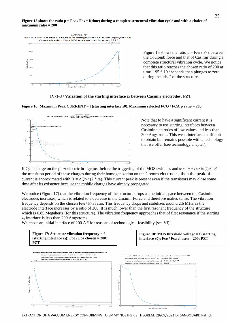
Figure 15: shows the ratio p = FCO / FCA = f(time) during a complete structural vibration cycle and with a choice of
maximum ratio = 200
Figure 16: Maximum Peak CURRENT = f (starting interface z0), Maximum selected FCO / FCA p ratio = 200
Figure 17: : Structure vibration frequency = f (starting interface z0): Fco / Fca chosen = 200: PZT
Figure 18: MOS threshold voltage = f (starting interface z0): Fco / Fca chosen = 200: PZT
Figure 19: maximum current = f (length of the Casimir electrode ls), starting interface = 200 A °, selected coefficient
of proportionality = p = Fco/Fca = 2
Figure 20: Threshold Voltage = f (length of the Casimir electrode ls), starting interface = 200 A °, selected
coefficient of proportionality = p = Fco / Fca = 2
Figure 21: threshold voltage = f (piezoelectric bridge width), Starting interface = 200 A °: Fco / Fca chosen = 10
Figure 22: current = f (piezoelectric bridge width), Starting interface = 200 A °: Fco / Fca chosen = 10
Figure 23: CURRENT = f (the thickness ap of the piezoelectric bridge), Starting interface = 200 A °:
Fco / Fca chosen = 10
Figure 24: Threshold of the MOS = f(Thickness of piezoelectric film ), start Interface = 200 A° with a choice
Fco/Fca =10
Figure 25: Structure vibration frequency = f (the thickness ap of the piezoelectric bridge),
Starting interface = 200 A °: Fco / Fca chosen = 10
Figure 25: Peak current = f (Ratio p = FCO / FCA), Starting interface = 200 A ° Piezoelectric material = PZT
Figure 26: Figure 26; current of the MOS = f (ratio = Fco/Fca), start Interface = 200 A°
piezoelectric material = PZT
Figure 27 Threshold voltage of the MOS = f (ratio = Fco/Fca), start Interface = 200 A°
piezoelectric material = PZT
Figure 28: plot of the evolution of the Casimir inter-electrode interval as a function of time over two periods and
Ratio Fco / Fca = 10000: Inter-electrode Casimir interface = 200 A °
Figure 29: plot of the evolution of the Casimir inter-electrode interval as a function of time over two periods and an
Fco / Fca Ratio = 1000: Casimir inter-electrode interface = 200 A°
Figure 30: plot of the evolution of the Casimir inter-electrode interval as a function of time over two periods and a
Ratio Fco / Fca = 2. Casimir inter-electrode interface = 200 A °
Figure 31: Materials = PMN-PT: Coulomb and Casimir force as a function of the inter-electrode interface.
Starting interface = 200A °
Figure 32: Materials = PMN-PT: Coulomb and Casimir force as a function of time. Starting interface = 200A °
Figure 33: Materials = PMN-PT: Ratio p = FCO/FCA as a function of time. Starting interface = 200A °
Figure 34: Materials = PMN-PT: Coulomb Force / Casimir Force ratio as a function of the Casimir inter-electrode
interface. Starting interface = 200A °
Figure 35 Materials = PMN-PT: Peak Current delivered by the structure as a function of the Fco / Fca Ratio. Starting
interface = 200A °
Figure 36 Materials = PMN-PT: Current peak as a function of time obtained over 2 cycles.
Starting interface = 200A °
EXTRACTION OF A VACUUM ENERGY CONFORMING TO EMMY NOETHER'S THEOREM: 29/09/2021 Dr SANGOUARD Patrick
4 Figure 37: Materials = PMN-PT: Voltage peak across the 2 * 10-4 H choke as a function of the time obtained over
2 cycles. Starting interface = 200A °
Figure 38: Materials = PMN-PT: Voltage peak across the 2 * 10-4 H choke as a function of the FCO / FCA
Ratio. Starting interface = 200A °
Figure 39: Materials = PMN-PT: Threshold voltage of the Enriched or Depleted MOTS according to the FCO / FCA
Ratio. Start interface = 200A °
Figure 40: Materials = PMN-PT: Vibration frequency as a function of the FCO / FCA Ratio.
Starting interface = 200A °
Figure 41: Materials = PMN-PT: Current peak across the 2 * 10-4 H choke as a function of the starting interval
between Casimir electrodes. Starting interface = 200A °
Figure 42: Piezoelectric Material = AlN Casimir, Coulomb Force = f (Time) starts Interface = 200 A°
Figure 43: Piezoelectric Material = AlN Ratio Fco/ Fca = f (Time) starts Interface = 200 A°
Figure 44: Material = AlN Interval between Casimir electrodes = f (time) during two complete cycles:
Interface between starting electrodes = 200 A °
Figure 45: Principle of electronics for amplifying and rectifying a weak AC
Figure 46: Elementary stage for obtaining a negative voltage from the negative part of the alternative signal of the
transformer (coil)
Figure 47: Elementary stage for obtaining a positive voltage from the positive part of the alternative signal of the
transformer ( coil)
Figure 48: SPICE simulations of voltages, current, power of the transformation electronics into a direct voltage
(5.4 V) of an alternating input signal of 50 mV
Figure 49: SPICE simulations of the currents drawn by the transformer and the power consumed by this transformer.
Figure 50 / DC output voltages as a function of the number of elementary stages for AC input voltages of 20 mV and
the other of 100 mV.
Figure 51: influence of the coupling capacitance on the amplification of the input signal
Figure 52 / Evolution of the DC output voltage as a function of the amplitude of the AC input signal for a frequency
of 150 kHz
Figure 53 / Evolution of the power supplied in nW by the source as a function of the amplitude of the voltage
supplied in mV.
Figure 54: Summary of the characteristics of the circuit for transforming a voltage of a few millivolts into a direct
voltage of a few volts and without any power supply circuit.
Figure 55: S.O.I technology for making the elements of the “doubler”
Figure 56 extract de [7]
Figure 57: Growth of SiO2 oxide on silicon
Figure 58: Distribution of thickness
Figure 59: etching of S.O.I silicon
Figure 60: Engraving of the protective metal rear face of the S.O.I.
Figure 61: deposition and etching of the piezoelectric layer
Figure 62: Metal deposit, Metal engraving
Figure 63: view of the Casimir device on the rear face, engraving on the rear face of the structures.
Figure 64: Adjusted growth of metal oxide under the electronic control, front view of the Casimir device
Figure 65: Position of the mobile Casimir electrode when the Coulomb force appears
Fig 66: Displacement of the mobile Casimir electrode during the appearance of the Coulomb force
Figure 67: general appearance of the device studied, forces and applied moments
Figure 68: view of the deformed bridge
Figure 69 : width , length , thickness of the bridge
Figure 70: a / Forces, shear forces and Moments applied on the bridge. b / Variation of bending moment. c / Shape
and arrow of the bridge embedded at both ends. With: 0 = inflection points, zmax = arrow of the bridge
Figure 71; Section, Frenet trihedron
Figure 72: Numerical solution of equation 18
Figure 73 : ANSYS simulation of the resonant frequency of the piezoelectric
Figure 74: ANSYS simulation of the resonant frequency of the complete structure
EXTRACTION OF A VACUUM ENERGY CONFORMING TO EMMY NOETHER'S THEOREM: 29/09/2021 Dr SANGOUARD Patrick
5
ABSTRACT
This theoretical and preliminary work corresponds to the hope of extracting, without contradicting EMMY
NOETHER's invariance theorem, an energy that is omnipresent, isotropic, uniform and present in the entire universe:
that of the void!
This theoretical work shows that it should be possible to maintain over time a periodic vibration of a piezoelectric
structure which generates current peaks during a fraction of the period of vibration. This is achieved by controlling
automatically and at the opportune moments the perpetual and omnipresent action of Casimir attractive force
between two electrodes, by an opposite and greater Coulomb force of at least a factor of two.
This proportionality factor, Coulomb / Casimir Forces> = 2, is determined by the threshold voltage of enriched or
depleted MOS transistors and defined during the manufacture of the device.
The attractive Casimir force appearing between the two electrodes of a reflector deforms a piezoelectric bridge,
which automatically induces the electric charges used by a Coulomb force on the return electrode.
As long as the electric voltage, generated by the electric charges on one side of the piezoelectric bridge and
connected to the gate of an enriched MOS transistor (MOSE) is below its threshold voltage, this transistor remains
blocked. The electrical charges on the other side of the bridge are on the source of this transistor and remain
confined to the moving electrode of the Casimir reflector. During this phase, the Coulomb return electrode is then
grounded by closing the circuit consisting of series depleted MOS (MOSD). Likewise, the fixed electrode of the
Casimir reflector is continuously grounded. The Coulomb force between the two electrodes of the Casimir reflector
and between the piezoelectric bridge and the Coulomb return electrode is then zero.
Depending on the deformation of the piezoelectric bridge, the electric charges present on the two electrodes
of the piezoelectric bridge increase. They therefore increase on the gates of the enriched or depleted MOS and
generate an electrical voltage greater than the threshold voltages of the MOSE and MOSD transistors. Thus, the
circuit formed by MOSE in parallel closes and that formed by MOSD in series opens, then isolating the fixed return
electrode from ground, which allows the charges present on the source to be distributed uniformly over this electrode.
recall and be trapped there.
Electric charges of opposite sign are then distributed over the two electrodes, one on one side of the
piezoelectric bridge, the other on the return electrode! So , an attractive Coulomb force who can be greater than and
in the opposite direction to that of Casimir then develops between these return electrodes. This attractive Coulomb
force moves the two electrodes away of the Casimir reflector, reducing then canceling the deformation of the bridge.
It automatically disappears when the deformation of the piezoelectric bridge is canceled out, letting the Casimir
force again dominate and deform this bridge again for a new cycle!
The device is found in the initial conditions which causes the structure to vibrate.
When homogenizing the electrical charges on both sides of the return electrode, periodic current peaks appear for a
fraction of the device's vibration time. These peaks of currents passing through an inductor spontaneously induce
peaks of alternating voltages at the terminals of this device.
Electronics without any power supply then transforms these weak alternating signals into a direct voltage of
several volts.
To manufacture these different structures, we are proposing an original technology making it possible to produce
these electronics without power supply, as well as that of the control of the very weak interfaces between the
electrodes of the Casimir reflector and that of the return electrodes of the vibrating structure!
The Casimir and Coulomb forces, the current or voltage peaks appear spontaneously and without input of any
external energy, likewise the transformation electronics have no power supply.
The structure automatically enters vibration thus inducing current and voltage peaks converted into a usable direct
voltage.
Everything is only a consequence of the existence of the isotropic, homogeneous, and omnipresent Casimir force due
to the quantum fluctuations of the vacuum.
This set does not seem to contradict Emily Noether's theorem!
"In the universe, everything is energy, everything is vibration, from the infinitely small to the infinitely large" Albert Einstein.
"A person who has never made mistakes has never tried to innovate." Albert Einstein

EXTRACTION OF A VACUUM ENERGY CONFORMING TO EMMY NOETHER'S THEOREM: 29/09/2021 Dr SANGOUARD Patrick
6 I / OBTAINING AN ELECTRIC CURRENT FROM VACUUM?
I1: Introduction
We know that the quantum vacuum, the energy vacuum, the absolutely nothing, does not exist!
This statement has been proven multiple times and noted in particular by:
• Lamb's shift (1947) of atomic emission frequencies.
• By the force of Van der Waals which plays a very important physicochemical role and had an interpretation
quantum 1930 [London] when two atoms are coupled to the same fluctuations in vacuum.
• By the experimental verification (1958) of the existence of a force equated by Casimir in 1948. This so-
called Casimir force was measured for the first time in 1997
• By Hawking's radiation theory, predicted in 1974 and observed on September 7, 2016.
Hawking's radiation:
The vacuum of physicists is like a kind of ocean full of energy that constantly fluctuates around a mean value called
zero and considered as the benchmark. This vacuum is often pictured and metaphorically compared to a sea of
particles and antiparticles, which go in pairs, annihilate, and then endlessly reconstitute. The entire universe would
have emerged from it during the BIG-BANG over 13.75 billion years ago! Hawking radiation is radiation that a
black hole must emit, due to the laws of quantum mechanics on vacuum, and which causes it to evaporate through
loss of mass and angular momentum if the black hole is rotating (black hall of Herr) and electrically charged. if it is
electrically charged (Kerr–Newman) .
Quantum Casimir force:
It is a force appearing between two parallel conductive plates, not electrically charged and very close to each other. It
is most often attractive but can also be repellent depending on the characteristics of the reflectors constituting these
two plates.
1 / The quantum fluctuations of the vacuum are present in any quantum field theory. The quantum Casimir
effect is due to fluctuations in the electromagnetic field, described by the theory of quantum electrodynamics and
theorized by Hendrik Casimir in 1948.
2 / The thermal Casimir effect in vacuum was predicted by Yevgeny LIFCHITS in 1956 when he realized
that classical thermal fluctuations should lead to an analogue of the Casimir effect theoretically predicted in the
quantum domain. Various physicists in particular considered the forces exerted between solids or liquids separated
by a fluid and these theorists predicted in 1961 that if the properties (more precisely, the refractive indices) of
materials are well chosen, the Casimir force could then be repulsive . This repulsive force was measured in 2009 by
F. Capasso and his colleagues who demonstrated a repulsive Casimir force of the order of 120 piconewtons when a
gold plate and a gold microbead are separated by twenty. of nanometers.
I.2 / Brief presentation of Casimir's force The vacuum energy is the zero-point energy of all fields (tensorial and scalar) in space, which for the standard model
includes the electromagnetic field, gauge fields, fermionic fields, as well than the Higgs field which is responsible
for the mass of particles and with which photons do not interact. In quantum field theory, this vacuum energy
defined as zero, is the ground state of fields! In cosmology, vacuum energy is a possible explanation for Einstein's
cosmological constant.
It has been observed and shown theoretically that this so-called zero-point energy, is non-zero for a simple quantum
harmonic oscillator, since its minimum energy is equal to with the natural frequency of the
oscillator, and h the Planck's constant.
Originally [1], the Casimir effect is derived from statistical fluctuations in total vacuum energy and is revealed by
the presence of two perfect and plane reflectors. The Casimir effect is the attraction (in general) between two plates
separated by a vacuum. In this approach, this Casimir energy is the ECA part of the vacuum energy which is a
function of the zS separation of the Casimir plates with:
This Casimir energy is proportional to the reduced Planck constant h, to the speed of light c and to the surface S of
the reflectors (in the limit where the edge effects of the plates are negligible, which then imposes large dimensions of
the reflectors compared to that of the separation of the plates).
The force of Casimir FCA between the two reflectors is then the derivative compared to zs of this energy thus:
(1)
EXTRACTION OF A VACUUM ENERGY CONFORMING TO EMMY NOETHER'S THEOREM: 29/09/2021 Dr SANGOUARD Patrick
7 This Casimir force, proportional to the surface, defines a pressure FCA / S which depends only on the distance zs
4
between the reflecting plates. This local approach greatly facilitates the formulations of Casimir's forces [1,2].
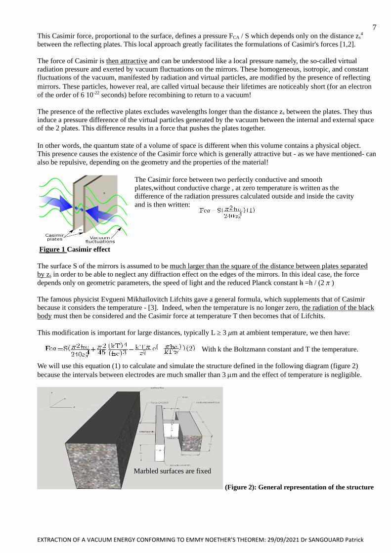
The force of Casimir is then attractive and can be understood like a local pressure namely, the so-called virtual radiation pressure and exerted by vacuum fluctuations on the mirrors. These homogeneous, isotropic, and constant
fluctuations of the vacuum, manifested by radiation and virtual particles, are modified by the presence of reflecting
mirrors. These particles, however real, are called virtual because their lifetimes are noticeably short (for an electron
of the order of 6 10-22 seconds) before recombining to return to a vacuum!
The presence of the reflective plates excludes wavelengths longer than the distance zs between the plates. They thus
induce a pressure difference of the virtual particles generated by the vacuum between the internal and external space
of the 2 plates. This difference results in a force that pushes the plates together.
In other words, the quantum state of a volume of space is different when this volume contains a physical object.
This presence causes the existence of the Casimir force which is generally attractive but - as we have mentioned- can
also be repulsive, depending on the geometry and the properties of the material!
Figure 1 Casimir effect
The surface S of the mirrors is assumed to be much larger than the square of the distance between plates separated
by zs in order to be able to neglect any diffraction effect on the edges of the mirrors. In this ideal case, the force
depends only on geometric parameters, the speed of light and the reduced Planck constant h =h / (2 )
The famous physicist Evgueni Mikhaïlovitch Lifchits gave a general formula, which supplements that of Casimir
because it considers the temperature - [3]. Indeed, when the temperature is no longer zero, the radiation of the black
body must then be considered and the Casimir force at temperature T then becomes that of Lifchits.
This modification is important for large distances, typically L ≥ 3 m at ambient temperature, we then have:
With k the Boltzmann constant and T the temperature.
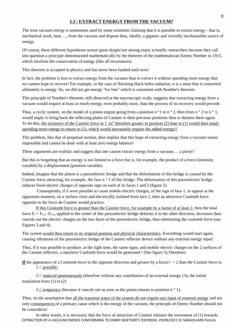
We will use this equation (1) to calculate and simulate the structure defined in the following diagram (figure 2)
because the intervals between electrodes are much smaller than 3 m and the effect of temperature is negligible.
(Figure 2): General representation of the structure
The Casimir force between two perfectly conductive and smooth
plates,without conductive charge , at zero temperature is written as the
difference of the radiation pressures calculated outside and inside the cavity
and is then written:
Marbled surfaces are fixed
EXTRACTION OF A VACUUM ENERGY CONFORMING TO EMMY NOETHER'S THEOREM: 29/09/2021 Dr SANGOUARD Patrick
8
I.3 / EXTRACT ENERGY FROM THE VACUUM?
The term vacuum energy is sometimes used by some scientists claiming that it is possible to extract energy - that is,
mechanical work, heat…., from the vacuum and dispose thus, ideally, a gigantic and virtually inexhaustible source of
energy.
Of course, these different hypotheses arouse great skepticism among many scientific researchers because they call
into question a principle demonstrated mathematically by the theorem of the mathematician Emmy Noether in 1915,
which involves the conservation of energy (like all invariances).
This theorem is accepted in physics and has never been faulted until now!
In fact, the problem is less to extract energy from the vacuum than to extract it without spending more energy that
we cannot hope to recover! For example, in the case of Hawking black holes radiation, it is a mass that is converted
ultimately in energy. So, we did not get energy "for free" which is consistent with Noether's theorem.
This principle of Noether's theorem, still observed at the macroscopic scale, suggests that extracting energy from a
vacuum would require at least as much energy, even probably more, than the process of its recovery would provide.
Thus, a cyclic system, on the model of a piston engine going from a position n °1 to n ° 2, then from n ° 2 to n ° 1,
would imply to bring back the reflecting plates of Casimir to their previous positions then to dismiss them again.
To do this, the existence of the Casimir force in 1 /zs4 therefore greater in position (2) than in (1) would then imply
spending more energy to return to (1), which would necessarily require the added energy!!
This problem, like that of perpetual motion, then implies that this hope of extracting energy from a vacuum seems
impossible and cannot be done with at least zero energy balance!
These arguments are realistic and suggest that one cannot extract energy from a vacuum…. a priori?
But this is forgetting that an energy is not limited to a force but is, for example, the product of a force (intensity
variable) by a displacement (position variable).
Indeed, imagine that the piston is a piezoelectric bridge and that the deformation of this bridge is caused by the
Casimir force attracting, for example, the face n ° 1 of this bridge. The deformation of this piezoelectric bridge
induces fixed electric charges of opposite sign on each of its faces 1 and 2 (figure 5).
Consequently, if it were possible to cause mobile electric charges, of the sign of face 1, to appear at the
opportune moment, on a surface close and electrically isolated from face 2, then an attractive Coulomb force
opposite to the force de Casimir would practice.
If this Coulomb force is greater than the Casimir force, for example by a factor of at least 2, then the total
force Ft = FCA -FCO, applied to the center of this piezoelectric bridge deforms it in the other direction, decreases then
cancels out the electric charges on the two faces of the piezoelectric bridge, thus eliminating the coulomb force (see
Figures 3 and 4).
The system would then return to its original position and physical characteristics. Everything would start again,
causing vibrations of the piezoelectric bridge of the Casimir reflector device without any external energy input!
Thus, if it was possible to produce, at the right time, the same signs, and mobile electric charges on the 2 surfaces of
the Casimir reflector, a repulsive Coulomb force would be generated ! (See figure 5).Therefore:
If the appearance of a Coulomb force in the opposite direction and greater by a factor> = 2 than the Casimir force is:
1 /: possible:
2 /: induced spontaneously (therefore without any contribution of an external energy ) by the initial
translation from (1) to (2)
3 /: temporary (because it cancels out as soon as the piston returns to position n ° 1).
Then, on the assumption that all the transient states of the system do not require any input of external energy and are
only consequences of a primary cause which is the energy of the vacuum, the principle of Emmy Noether should not
be contradicts!
In other words, it is necessary that the force of attraction of Casimir initiates the movement of (1) towards
EXTRACTION OF A VACUUM ENERGY CONFORMING TO EMMY NOETHER'S THEOREM: 29/09/2021 Dr SANGOUARD Patrick
9 (2), creates by itself and without the contribution of any external energy a higher opposing force of a factor 2 and
which can be at an opportune moment to bring the piston back from (2) to (1) then vanishes!
In this case, no external energy being necessary, the overall conservation of energy would not be violated,
because the extraction of energy from the vacuum would have an energy balance at least zero.
Indeed, by moving the plates, one modifies the possible wavelengths (because in resonance with the gap
between the plates) of the virtual radiations of the radiation leaving the vacuum and at the origin of the Casimir force,
thus varying the energy of the void itself!
The fixed electric charges on the two metallized faces of the piezoelectric bridge are of opposite signs and attracts
from the mass of the mobile charges of opposite signs (figure 5).
Let us imagine that the whole of the return electrode is in two parts of equal areas but separated by a switch circuit
consisting of MOSN and MOSP enriched, in parallel and of threshold voltage VtNE = - VtPE. (Figure 5) The first part
of this metallic return electrode and surface Sp1 consists of one of the faces of the piezoelectric bridge and carries
mobile electric charges Qm = - QF.
The second part of this metal electrode is earthed via another switch circuit made up of depleted MOSN and MOSP,
in series and of the same threshold voltage as the enriched MOSN and MOSP: VtND = VtPE> 0 and VtPD = VtNE <0
(See figure 5).
These switch circuits (circuit 1 = MOSN and MOSP enriched in parallel, circuit 2 = MOSND and MOSPD in
depletion and in series), are designed so that they open and close in opposition.
When circuit 1 then opens or closes, at the same time switch circuit 2 closes or opens, thus isolating this return
electrode from the ground (see figure 5). This opposite behavior of the switch circuits can be seen in Figure 6.
So, when circuit 1 is open, the two parts of the return electrodes are grounded through circuits 2, on the other hand
when circuit 1 closes the two parts of the return electrodes are isolated! (Figure 5)
The electric field inside a perfect conductor being zero, the mobile charges attracted to the first part of the return
electrode are redistributed on the two parts of this electrode in the ratio of the homogenization surfaces , that is to
say ½ and are opposite the other face n ° 2 of the bridge which has an opposite electric charge!
One then develops, between these isolated electrodes an attractive Coulomb force which is in the opposite direction
to the Casimir force and can be greater than it! (See figure 3 + 4 + 5)
Now, we know that in the case of a deformation perpendicular to the polarization of a piezoelectric layer and caused
by an FCA force, the fixed charges QF induced by the deformation of this piezoelectric layer are proportional to the
Casimir force FCA and are therefore in 1/zs4, with (3), [5] and [6]. With d31 = piezoelectric coefficient
(CN-1), lp, ap respectively length and thickness (m) of the piezoelectric bridge (figure 5). These fixed electric charges
on the two metallized faces of the piezoelectric bridge have opposite signs and attract mobile charges of opposite
signs from the mass (figure 5).
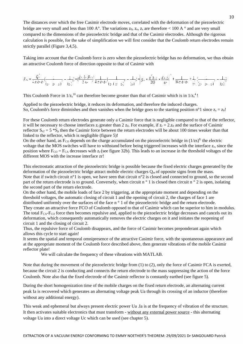
Thus, when it is effective, the Coulomb return force FCO is in 1/zs10 because on the one hand in (QF/2) 2 (therefore in
1/zs8) but also in 1/(zr + z0 - zs) 2 because depending of the distances zr + z0 - zs between return electrode n ° 1 and
face n ° 2 of the piezoelectric bridge . With zr the initial distance between the opposite face of the piezoelectric
bridge and the return electrode, zs = distance between Casimir electrodes, time dependent, and z0 = initial distance
between Casimir electrodes (see figure 3 + 4 + 5) and figure below. We will choose in the following MATLAB
simulations (unless otherwise specified), the same interface between return electrode zr as that attributed to the
initial interface z0 between Casimir reflectors
Initial positions of
the electrodes
Undeformable bond
between electrodes
z0-zs = Displacement of
the piezoelectric bridge
and the Casimir electrode
Time-dependent positions
of the electrodes
Zr , z0 Initial Interface
electrodes
EXTRACTION OF A VACUUM ENERGY CONFORMING TO EMMY NOETHER'S THEOREM: 29/09/2021 Dr SANGOUARD Patrick
10 The distances over which the free Casimir electrode moves, correlated with the deformation of the piezoelectric
bridge are very small and less than 100 A°. The variations z0, ze, zs are therefore < 100 A ° and are very small
compared to the dimensions of the piezoelectric bridge and that of the Casimir electrodes. Although the rigorous
calculation is possible, for the sake of simplification we will first consider that the Coulomb return electrodes remain
strictly parallel (Figure 3,4,5).
Taking into account that the Coulomb force is zero when the piezoelectric bridge has no deformation, we thus obtain
an attractive Coulomb force of direction opposite to that of Casimir with
This Coulomb Force in 1/zs10 can therefore become greater than that of Casimir which is in 1/zs
4 !
Applied to the piezoelectric bridge, it reduces its deformation, and therefore the induced charges.
So, Coulomb's force diminishes and then vanishes when the bridge goes to the starting position n°1 since zs = z0!
For these Coulomb return electrodes generate only a Casimir force that is negligible compared to that of the reflector,
it will be necessary to choose interfaces zr greater than 2 z0. For example, if zr = 2.z0 and the surface of Casimir
reflector Ss2 = 5 *Sp then the Casimir force between the return electrodes will be about 100 times weaker than that
linked to the reflector, which is negligible (figure 5)!
On the other hand, as FCO depends on the charge accumulated on the piezoelectric bridge in (1/zs)8, the electric
voltage that the MOS switches will have to withstand before being triggered increases with the interface zr, since the
position where FCO = FCA decreases with zr (see figure 32b). This leads to an increase in the threshold voltages of the
different MOS with the increase interface zr!
This electrostatic attraction of the piezoelectric bridge is possible because the fixed electric charges generated by the
deformation of the piezoelectric bridge attract mobile electric charges Qm of opposite signs from the mass.
Note that if switch circuit n°1 is open, we have seen that circuit n°2 is closed and connected to ground, so the second
part of the return electrode is to ground. Conversely, when circuit n ° 1 is closed then circuit n ° 2 is open, isolating
the second part of the return electrode.
On the other hand, the mobile loads of face 2 by triggering, at the appropriate moment and depending on the
threshold voltages, the automatic closing of circuit 1 and the opening of circuit 2, the charges of face 1 are
distributed uniformly over the surfaces of the face n ° 1 of the piezoelectric bridge and the return electrode.
They create an attractive force FCO of Coulomb opposed to that of Casimir which can be superior to him in modulus.
The total FCA-FCO force then becomes repulsive and, applied to the piezoelectric bridge decreases and cancels out its
deformation, which consequently automatically removes the electric charges on it and initiates the reopening of
circuit 1 and the closing of circuit 2.
Thus, the repulsive force of Coulomb disappears, and the force of Casimir becomes preponderant again which
allows this cycle to start again!
It seems the spatial and temporal omnipresence of the attractive Casimir force, with the spontaneous appearance and
at the appropriate moment of the Coulomb force described above, then generate vibrations of the mobile Casimir
reflector plate!
We will calculate the frequency of these vibrations with MATLAB.
Note that during the movement of the piezoelectric bridge from (1) to (2), only the force of Casimir FCA is exerted,
because the circuit 2 is conducting and connects the return electrode to the mass suppressing the action of the force
Coulomb. Note also that the fixed electrode of the Casimir reflector is constantly earthed (see figure 5).
During the short homogenization time of the mobile charges on the fixed return electrode, an alternating current
peak Ia is recovered which generates an alternating voltage peak Ua through its crossing of an inductor (therefore
without any additional energy).
This weak and ephemeral but always present electric power Ua .Ia is at the frequency of vibration of the structure.
It then activates suitable electronics that must transform - without any external power source - this alternating
voltage Ua into a direct voltage Uc which can be used (see chapter 5).
EXTRACTION OF A VACUUM ENERGY CONFORMING TO EMMY NOETHER'S THEOREM: 29/09/2021 Dr SANGOUARD Patrick
11 This electronics was designed when I was working at ESIEE and on abandoned sensors. This electronics was
necessary for this problem sensors which, as their name suggests, are abandoned, therefore without internal energy.
It works very well in SPICE simulation (see part V).
If all the components of this project are successful (principle of extracting energy from the vacuum + device
generating current peaks at the vibration frequency of the system and converted in peak of voltage by a coil +
transformation electronics + technology for realization the device selected) , all without any additional energy, the
principle of Noether should be validated and the vacuum could then be considered as a simple medium, with which
it is possible to exchange energy!
This is the aim of this pre-work and this report.
EXTRACTION OF A VACUUM ENERGY CONFORMING TO EMMY NOETHER'S THEOREM: 29/09/2021 Dr SANGOUARD Patrick
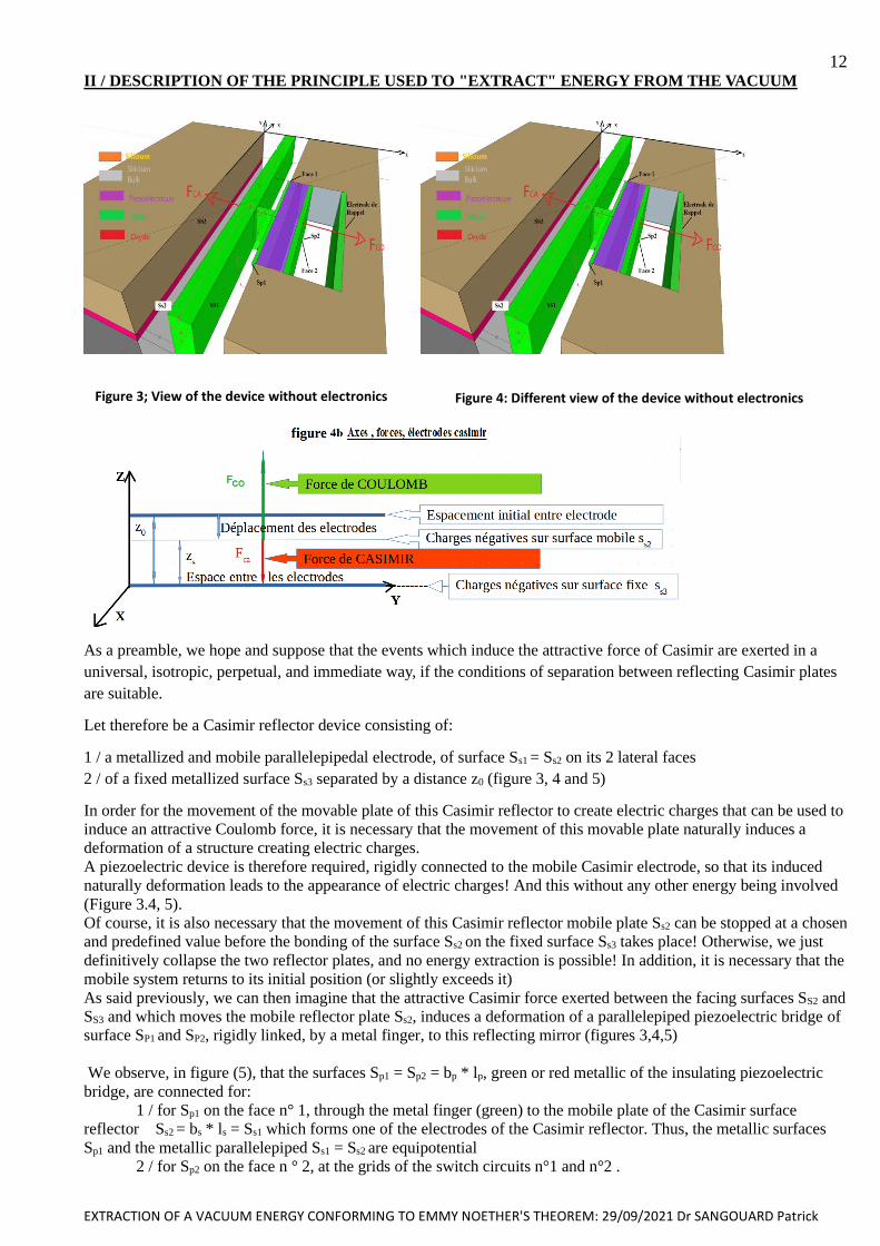
12 II / DESCRIPTION OF THE PRINCIPLE USED TO "EXTRACT" ENERGY FROM THE VACUUM
Figure 4: Different view of the device without electronics
As a preamble, we hope and suppose that the events which induce the attractive force of Casimir are exerted in a
universal, isotropic, perpetual, and immediate way, if the conditions of separation between reflecting Casimir plates
are suitable.
Let therefore be a Casimir reflector device consisting of:
1 / a metallized and mobile parallelepipedal electrode, of surface Ss1 = Ss2 on its 2 lateral faces
2 / of a fixed metallized surface Ss3 separated by a distance z0 (figure 3, 4 and 5)
In order for the movement of the movable plate of this Casimir reflector to create electric charges that can be used to
induce an attractive Coulomb force, it is necessary that the movement of this movable plate naturally induces a
deformation of a structure creating electric charges.
A piezoelectric device is therefore required, rigidly connected to the mobile Casimir electrode, so that its induced
naturally deformation leads to the appearance of electric charges! And this without any other energy being involved
(Figure 3.4, 5).
Of course, it is also necessary that the movement of this Casimir reflector mobile plate Ss2 can be stopped at a chosen
and predefined value before the bonding of the surface Ss2 on the fixed surface Ss3 takes place! Otherwise, we just
definitively collapse the two reflector plates, and no energy extraction is possible! In addition, it is necessary that the
mobile system returns to its initial position (or slightly exceeds it)
As said previously, we can then imagine that the attractive Casimir force exerted between the facing surfaces SS2 and
SS3 and which moves the mobile reflector plate Ss2, induces a deformation of a parallelepiped piezoelectric bridge of
surface SP1 and SP2, rigidly linked, by a metal finger, to this reflecting mirror (figures 3,4,5)
We observe, in figure (5), that the surfaces Sp1 = Sp2 = bp * lp, green or red metallic of the insulating piezoelectric
bridge, are connected for: 1 / for Sp1 on the face n° 1, through the metal finger (green) to the mobile plate of the Casimir surface
reflector Ss2 = bs * ls = Ss1 which forms one of the electrodes of the Casimir reflector. Thus, the metallic surfaces
Sp1 and the metallic parallelepiped Ss1 = Ss2 are equipotential
2 / for Sp2 on the face n ° 2, at the grids of the switch circuits n°1 and n°2 .
Figure 3; View of the device without electronics

EXTRACTION OF A VACUUM ENERGY CONFORMING TO EMMY NOETHER'S THEOREM: 29/09/2021 Dr SANGOUARD Patrick
13 The deformations caused by the attractive force of Casimir, then produce fixed electric charges for example
Qfn1 = - Qfp2, on the faces Sp1 and Sp2 of the insulating piezoelectric bridge. These fixed charges in turn attract, from
the immediate environment (mass or earth) to which they are connected by circuits 2, mobile electric charges Qmp1
and Qmn2, respectively. These charges are distributed over the metallized surfaces deposited on the insulating
piezoelectric bridge, therefore on Sp2 and the gates of the transistors of circuits 1 and 2 as well as on Sp1, the metal
block, the sources of the transistors of circuit 1 and the two coupling capacitors of the electronic transformation
circuit. (See figures 5 +45)
Figures 5: general configuration of the device: MOS grid connections (Face 2 of the piezoelectric bridge: red),
Source connections (Face 1 of the piezoelectric bridge: green)
Let SMOS be the surface of the gates of the MOS of switch circuits 1 and 2. The mobile charges, for example positive
Qmp2, located on the surface Sp2 of face 2 going to the gate of a MOSNE enriched transistor in the ratio
Qmp2MOS = Qmp2 * SMOS / Sp2 , then produce a positive voltage VG = Qmp2 MOS / COX on the gate of the MOS transistors,
with Cox the gate capacitance of the MOS transistors.
Depending on the sign of these mobile charges on the gates of the MOSNE or MOSPE transistors, they can turn one
of them ON, if they are sufficient to induce a voltage VG greater than their threshold voltage VTE, positive for the
MOSNE transistor and negative on the MOSPE transistor in parallel.
The nature of these charges depends on the initial polarization of the deposited piezoelectric parallelepiped and on
the direction of the deformation imposed by the Casimir force. The sign of these mobile charges on the surfaces Sp1
and Sp2 depending on the real polarization obtained during the realization of the piezoelectric material of this bridge,
it is the reverse which occurs if the mobile charges are negative on Sp2, hence the parallel setting of switches! (See
figure 5)
As long as this voltage on face 2 of the bridge, for example positive, is less than the threshold voltage VTNE of this
MOSNE transistor, the latter remains blocked!. Consequently, the mobile charges Qmn1 = - Qmp2 located on the
other face Sp1 of the deformed piezoelectric device (connected by a metal block to Ss2) and connected to the
sources of the MOSNE and MOSPE remain on these surfaces and do not propagate on the surface of the return
electrode. The MOS switches N and P depleted in series from the switch circuit 2 are then on and connect this return
electrode to ground (FIG. 5).
On the other hand, if this voltage VG becomes greater than the threshold voltage VTNE of the enriched MOSNE, it
becomes conducting, and circuit 2 is then blocked, so the mobile charges Qmn1, located on Sp1 and the metal block
can cross the MOSNE to homogenize the charge density on all the return electrodes.
These electric charges pass through the self-LIN in series, (figure 5).
EXTRACTION OF A VACUUM ENERGY CONFORMING TO EMMY NOETHER'S THEOREM: 29/09/2021 Dr SANGOUARD Patrick
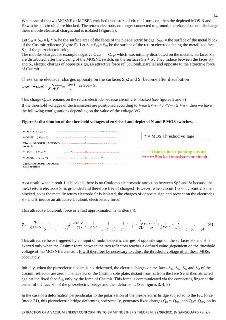
14 When one of the two MOSNE or MOSPE enriched transistors of circuit 1 turns on, then the depleted MOS N and
P switches of circuit 2 are blocked. The return electrode, no longer connected to ground, therefore does not discharge
these mobile electrical charges and is isolated (Figure 5).
Let Sp1 = Sp2 = lp * bp be the surface area of the faces of the piezoelectric bridge, Sbloc = the surface of the metal block
of the Casimir reflector (figure 5). Let Sr = Sp2 = Sp1 be the surface of the return electrode facing the metallized face
Sp2 of the piezoelectric bridge.
The mobiles charges for example negative Qmn1 = - Qmp2 which was initially distributed on the metallic surfaces Sp1
are distributed, after the closing of the MOSNE switch, on the surfaces Sp1 + Sr. They induce between the faces Sp2
and Sr, electric charges of opposite sign, an attractive force of Coulomb, parallel and opposite to the attractive force
of Casimir,
These same electrical charges opposite on the surfaces Sp2 and Sr become after distribution
. as Sp1= Sr
This charge Qmn1f remains on the return electrode because circuit 2 is blocked (see figures 5 and 6)
If the threshold voltages of the transistors are positioned according to VTND VTPE <0 <VTNE VTPD, then we have
the following configurations depending on the value of the voltage VG
Figure 6: distribution of the threshold voltages of enriched and depleted N and P MOS switches.
MOSPD (VTPD * ) --------------------------0--- ----------*++++++++++
MOSND ( VTND *) ++++++++++*------------0----------------------------
Circuit MOSPD , MOSND +++++-------------0--------------++++++++
en série
MOSPE ( VTPE*) ---- -*++ +++++++0+++++++++++++++++++++++
MOSNE ( VTNE *) ++++++++++++++++++++0++++++++++ *--------------
Circuit MOSPE , MOSNE ----------+++++++ 0+++++++++-------------------
En Parallèle
As a result, when circuit 1 is blocked, there is no Coulomb electrostatic attraction between Sp2 and Sr because the
metal return electrode Sr is grounded and therefore free of charges! However, when circuit 1 is on, circuit 2 is then
blocked, so as the metallic return electrode Sr is isolated, the charges of opposite sign and present on the electrodes
Sp2 and Sr induce an attractive Coulomb electrostatic force!
This attractive Coulomb force as a first approximation is written (4):
(4)
This attractive force triggered by an input of mobile electric charges of opposite sign on the surfaces Sp2 and Sr is
exerted only when the Casimir force between the two reflectors reaches a defined value ,dependent on the threshold
voltage of the MOSNE transistor. It will therefore be necessary to adjust the threshold voltage of all these MOSs
adequately.
Initially, when the piezoelectric beam is not deformed, the electric charges on the faces Sp1, Sp2, Ss2 and Ss3 of the
Casimir reflector are zero! The face Ss2 of the Casimir sole plate, distant from z0 from the face SS3 is then attracted
against the fixed face Ss3, only by the force of Casimir. This force is communicated via the connecting finger at the
center of the face Sp1 of the piezoelectric bridge and then deforms it. (See figures 3, 4, 5)
In the case of a deformation perpendicular to the polarization of the piezoelectric bridge subjected to the FCA force
(mode 31), this piezoelectric bridge deforming horizontally, generates fixed charges Qfp =-Qmn1 and Qfn=-Qmn2 on its
* = MOS Threshod voltage
Résultats de
traduction
MOS threshold voltage
Résultats de
traduction
MOS threshold voltage
------Transistor or passing circuit
+++++Blocked transistors or circuit
EXTRACTION OF A VACUUM ENERGY CONFORMING TO EMMY NOETHER'S THEOREM: 29/09/2021 Dr SANGOUARD Patrick
15
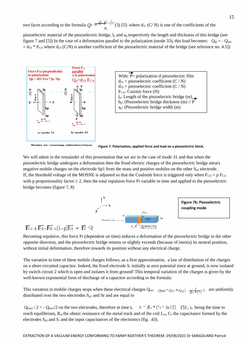
two faces according to the formula (3) [5]: where d31 (C/ N) is one of the coefficients of the
piezoelectric material of the piezoelectric bridge, lp and ap respectively the length and thickness of this bridge (see
figure 7 and [5]) In the case of a deformation parallel to the polarization (mode 33), this load becomes: Qfp = - Qmn
= d33 * FCA where d33 (C/N) is another coefficient of the piezoelectric material of the bridge (see reference no. 4.5])
Figure 7: Polarization, applied force and load on a piezoelectric block.
We will admit in the remainder of this presentation that we are in the case of mode 31 and that when the
piezoelectric bridge undergoes a deformation then the fixed electric charges of the piezoelectric bridge attract
negative mobile charges on the electrode Sp1 from the mass and positive mobiles on the other Sp2 electrode.
If, the threshold voltage of the MOSNE is adjusted so that the Coulomb force is triggered only when FCO = p FCA
with p proportionality factor 2, then the total repulsion force Ft variable in time and applied to the piezoelectric
bridge becomes (figure 7, 8)
& 1
Becoming repulsive, this force Ft (dependent on time) induces a deformation of the piezoelectric bridge in the other
opposite direction, and the piezoelectric bridge returns or slightly exceeds (because of inertia) its neutral position,
without initial deformation, therefore towards its position without any electrical charge.
The variation in time of these mobile charges follows, as a first approximation, a law of distribution of the charges
on a short-circuited capacitor. Indeed, the fixed electrode Sr initially at zero potential since at ground, is now isolated
by switch circuit 2 which is open and isolates it from ground! This temporal variation of the charges is given by the
well-known exponential form of discharge of a capacitor according to the formula:
This variation in mobile charges stops when these electrical charges Qmn are uniformly
distributed over the two electrodes Sp2 and Sr and are equal to
(5) , te being the time to Qmn2 / 2 = - Qmn1/2 on the two electrodes, therefore at time te
reach equilibrium, Rm the ohmic resistance of the metal track and of the coil Lin, Cs the capacitance formed by the
electrodes Sp2 and Sr and the input capacitances of the electronics (fig. .43).
With: P= polarization if piezoelectric film
d31 = piezoelectric coefficient (C / N)
d33 = piezoelectric coefficient (C / N)
FCA: Casimir force (N)
lp: Length of the piezoelectric bridge (m)
bp: (Piezoelectric bridge thickness (m) // P
ap: (Piezoelectric bridge width (m)
Force Fca perpendicular
to polarization Qp = d31 Fca * lp / bp
Force Fca parallel à la polarization
Qp=d33 FCA
lp à la polarisation
Qp=d33 FCA
lp à la polarisation
Qp=d33 FCA
bp à la polarisation
Qp=d33 FCA
bp à la polarisation
Qp=d33 FCA ap à la polarisation
Qp=d33 FCA
ap à la polarisation
Qp=d33 FCA
Figure 7b: Piezoelectric
coupling mode
EXTRACTION OF A VACUUM ENERGY CONFORMING TO EMMY NOETHER'S THEOREM: 29/09/2021 Dr SANGOUARD Patrick
16 This homogenization of electric charges within a metallic conductor:
1 / occurs when the gate voltage of the MOSs constituting circuits 1 and 2 exceeds their threshold voltage.
2 / induces an attraction of the piezoelectric structure in the direction opposite to that of Casimir
3 / decreases the deformation of the piezoelectric bridge and brings the gate voltage back below the
threshold voltage.
4 / The transistor MOS only turns off after the charges are homogenized during the short time te.
We therefore obtain a current peak during this homogenization with a duration te of the order of a nanosecond!
This current peak IIN circulating for the duration of time te is:
IIN =d(Qmn)/dt (6)
We therefore obtain a current peak during this homogenization with a duration te of the order of a nanosecond!
A current peak is obtained at time t = 0. With Qmn2 / 2 the charge which is distributed uniformly over the two
electrodes Sp2 and Sr.
Time t is counted from the closing of one of the transistors of circuit 1 and the opening of the switches of circuit 2.
This current peak IIN crossing a self LIN during the time te, induces a voltage UIN at the terminals of this self LIN as a
function of time according to the usual formula:
UIN =LIN* d(IIN)/dt = = =LIN * IIN * ln(2) / te (7)
There is therefore a voltage peak across the coil and the electronics appearing without power supply at time t = 0 !
As the deformations of the piezoelectric bridge cancel each other out during its "rise", the mobile charges on the
surfaces Sp1 as well as Sp2 also cancel each other out! As a result, the gate voltage on circuit 1 and 2 MOSs drops
below the threshold voltages and circuit 1 blocks. Circuit n°2 turns on again and connects face 2 of return electrode
to ground, so the electrical charges on the bridge and the Sr electrode cancel each other out! (See figure 5).
The force of Casimir FCA, still present, again attracts the metallic surface SS2 against SS3 and the events described
above are repeated. Casimir's force deforms this bridge again and it seems that all starts all over again!
The consequence is that the structure made up of the piezoelectric bridge, the connecting finger, the metal block
forming the mobile Casimir electrode starts to vibrate, with a frequency dependent:
• of the Casimir restoring force, and of the return electrode therefore of the starting z0 and zr separation interface
• geometric dimensions of the different electrodes,
• properties of the piezoelectric bridge,
• the choice of threshold voltages of the different MOS transistors
• the choice of conductive metal!
As we will see, this frequency is lower than that of the first resonant frequency of the mobile structure if the
initial interface z0 is not weak enough ( < 150 A°) to induce a sufficient Casimir force (see chapter V and X)!
An AC voltage peak UIN is therefore automatically recovered at the terminals of the solenoid LIN. This AC
voltage peak can then be rectified to a DC voltage of a few volts, by suitable electronics operating without power
supply (see amplification electronics without VI power supply).
Before moving on to theoretical calculations and mathematical simulations of the structure we wish to
emphasize that the alternating signal UIN is obtained without the input of any external energy!
Indeed, it is the Casimir force due to fluctuations in vacuum energy that induces a displacement of the mobile
electrode SS2 of the Casimir reflector and then naturally causes a deformation of the piezoelectric bridge. This
deformation by nature generates fixed electric charges in the structure of this piezoelectric bridge which is insulating.
EXTRACTION OF A VACUUM ENERGY CONFORMING TO EMMY NOETHER'S THEOREM: 29/09/2021 Dr SANGOUARD Patrick
17 These fixed charges then attract from the mass, opposing mobile charges on the metal electrodes Sp1 and SP2 of
this bridge. These mobile electric charges also go to the gates and the sources of enriched transistors of circuits 1 and
2 (FIG. 5). When the voltage developed by these mobile charges on the gates of the MOS transistors exceeds their
threshold voltages, then circuit n°1 naturally turns on and circuit n° 2 is blocked.
Depending on the value of the threshold voltages of the enriched MOS transistors of circuit n°1, the mobile charges
Qmn of face n°1 can then flow and reach the other fixed return electrode Sr via an inductor LIN and the input of the
electronics. As this Sr electrode is then electrically isolated by the automatic opening of circuit n°2, this mobile
electric charges are distributed uniformly over the two metal surfaces Sp2 and Sr of the Casimir reflector. The
charges on the SS2 and Sr electrodes being of opposite sign induce, without external energy input, a Coulomb force
which can be large (> 2 times) and opposite to the Casimir force.
This force moves away the mobile electrode SS2 of the Casimir reflector from SS3, and by this movement naturally
cancels the deformation and therefore the charges present on the piezoelectric bridge. The Coulomb force vanishes,
and the ever-present Casimir force then re-attracts the SS2 electrode and…. everything restarts.
The structure consisting of the piezoelectric bridge, the connecting finger and the mobile part of the Casimir
reflector then vibrates at a frequency depending on the geometric and physical characteristics of the Casimir
reflector and the piezoelectric bridge and this a priori without any energy input from our world!
In conclusions it seems (except errors) that all the electro-physical phenomena leading to a vibration of the structure
and to the production of a voltage modulation are only the consequence of a first phenomenon which is at the origin
of the Force of Casimir induced by fluctuations in vacuum energy.
They occur naturally and automatically without the input of any external energy except that of a vacuum ...!
We can then hope that this complete device extracts its operating energy from the Casimir force due to isotropic
fluctuations in vacuum and works without contradicting Noether's theorem….
But we know that the devil is hiding in the details!!
EXTRACTION OF A VACUUM ENERGY CONFORMING TO EMMY NOETHER'S THEOREM: 29/09/2021 Dr SANGOUARD Patrick
18
III / CALCULATION OF THE CURRENT GENERATED BY THE CASIMIR STRUCTURE
If the initial separation interface z0 is greater than 150 A °, the forces present are too weak to induce a vibration
frequency of the device corresponding to its first resonant frequency (see chapter V).
We sought the numerical solutions of the differential equations obtained and unfortunately insoluble analytically
when the device does not vibrate at its first resonant frequency!
III .1 / calculation of the frequency of vibration of the Casimir structure.
In order to verify whether the structure of figure 5 can enter into resonance at its first frequency (see Appendix) or
vibrate at another frequency under the action of the forces of Casimir and Coulomb, let us calculate the evolution in
time of the force of Casimir which is applied between the two electrodes separated by an initial distance z0.
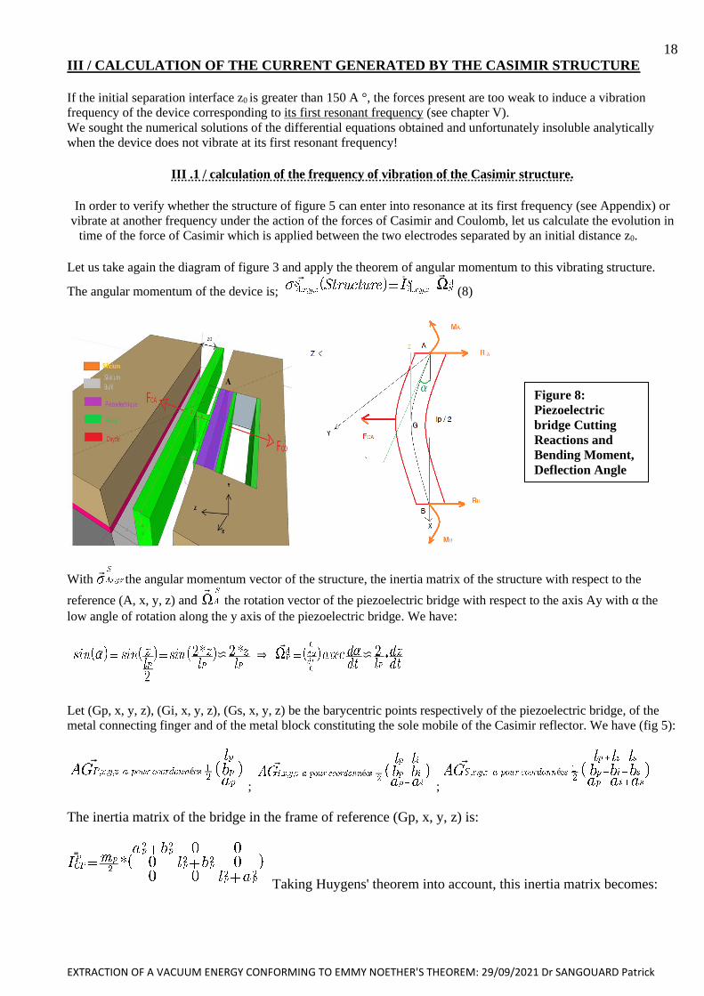
Let us take again the diagram of figure 3 and apply the theorem of angular momentum to this vibrating structure.
The angular momentum of the device is; v rr v
(8)
With v the angular momentum vector of the structure, the inertia matrix of the structure with respect to the
reference (A, x, y, z) and v the rotation vector of the piezoelectric bridge with respect to the axis Ay with α the
low angle of rotation along the y axis of the piezoelectric bridge. We have:
c & v c
Let (Gp, x, y, z), (Gi, x, y, z), (Gs, x, y, z) be the barycentric points respectively of the piezoelectric bridge, of the
metal connecting finger and of the metal block constituting the sole mobile of the Casimir reflector. We have (fig 5):
vé
;
vé
;
vé
The inertia matrix of the bridge in the frame of reference (Gp, x, y, z) is:
rr
Taking Huygens' theorem into account, this inertia matrix becomes:
Figure 8:
Piezoelectric
bridge Cutting
Reactions and
Bending Moment,
Deflection Angle
EXTRACTION OF A VACUUM ENERGY CONFORMING TO EMMY NOETHER'S THEOREM: 29/09/2021 Dr SANGOUARD Patrick
19
rr
(9)
The inertia matrix of the connecting finger is in the frame of reference (Gi, x, y, z):
Taking Huygens' theorem into account, this inertia matrix becomes:
rr
(10)
The inertia matrix of the connecting finger is in the frame of reference (GS, x, y,z) :
rr
Taking Huygens' theorem into account, this inertia matrix becomes:
rr
(11)
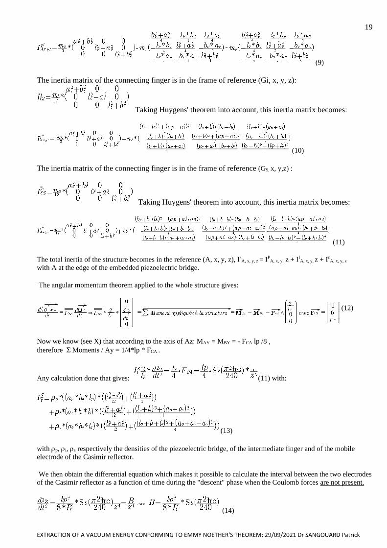
The total inertia of the structure becomes in the reference (A, x, y, z), IsA, x, y, z = IP
A, x, y, z + IIA, x, y, z + Ic
A, x, y, z
with A at the edge of the embedded piezoelectric bridge.
The angular momentum theorem applied to the whole structure gives:
& é à / (12)
Now we know (see X) that according to the axis of Az: MAY = MBY = - FCA lp /8 ,
therefore S Moments / Ay = 1/4*lp * FCA .
Any calculation done that gives: (11) with:
(13)
with p, i, s respectively the densities of the piezoelectric bridge, of the intermediate finger and of the mobile
electrode of the Casimir reflector.
We then obtain the differential equation which makes it possible to calculate the interval between the two electrodes
of the Casimir reflector as a function of time during the "descent" phase when the Coulomb forces are not present.
(14)
EXTRACTION OF A VACUUM ENERGY CONFORMING TO EMMY NOETHER'S THEOREM: 29/09/2021 Dr SANGOUARD Patrick
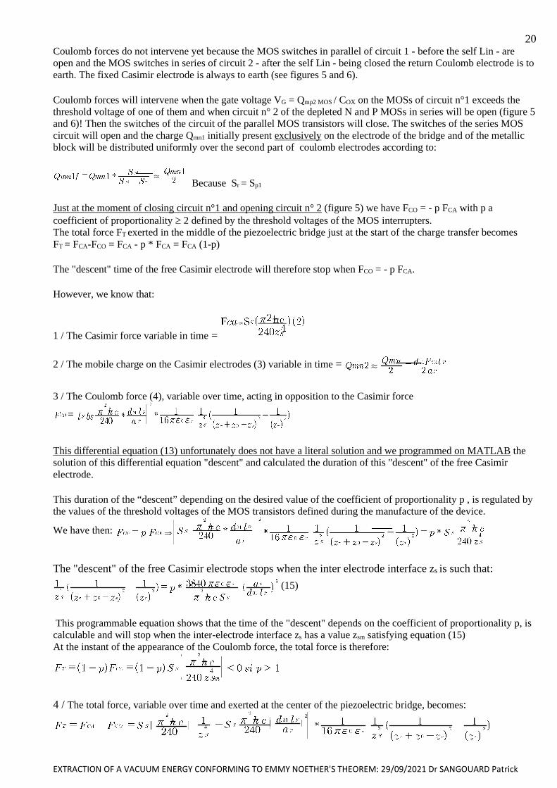
20 Coulomb forces do not intervene yet because the MOS switches in parallel of circuit 1 - before the self Lin - are
open and the MOS switches in series of circuit 2 - after the self Lin - being closed the return Coulomb electrode is to
earth. The fixed Casimir electrode is always to earth (see figures 5 and 6).
Coulomb forces will intervene when the gate voltage VG = Qmp2 MOS / COX on the MOSs of circuit n°1 exceeds the
threshold voltage of one of them and when circuit n° 2 of the depleted N and P MOSs in series will be open (figure 5
and 6)! Then the switches of the circuit of the parallel MOS transistors will close. The switches of the series MOS
circuit will open and the charge Qmn1 initially present exclusively on the electrode of the bridge and of the metallic
block will be distributed uniformly over the second part of coulomb electrodes according to:
. Because Sr = Sp1
Just at the moment of closing circuit n°1 and opening circuit n° 2 (figure 5) we have FCO = - p FCA with p a
coefficient of proportionality 2 defined by the threshold voltages of the MOS interrupters.
The total force FT exerted in the middle of the piezoelectric bridge just at the start of the charge transfer becomes
FT = FCA-FCO = FCA - p * FCA = FCA (1-p)
The "descent" time of the free Casimir electrode will therefore stop when FCO = - p FCA.
However, we know that:
1 / The Casimir force variable in time =
c
2 / The mobile charge on the Casimir electrodes (3) variable in time = .
3 / The Coulomb force (4), variable over time, acting in opposition to the Casimir force
This differential equation (13) unfortunately does not have a literal solution and we programmed on MATLAB the
solution of this differential equation "descent" and calculated the duration of this "descent" of the free Casimir
electrode.
This duration of the “descent” depending on the desired value of the coefficient of proportionality p , is regulated by
the values of the threshold voltages of the MOS transistors defined during the manufacture of the device.
We have then: &
The "descent" of the free Casimir electrode stops when the inter electrode interface zs is such that:
(15)
This programmable equation shows that the time of the "descent" depends on the coefficient of proportionality p, is
calculable and will stop when the inter-electrode interface zs has a value zsm satisfying equation (15)
At the instant of the appearance of the Coulomb force, the total force is therefore:
4 / The total force, variable over time and exerted at the center of the piezoelectric bridge, becomes:
EXTRACTION OF A VACUUM ENERGY CONFORMING TO EMMY NOETHER'S THEOREM: 29/09/2021 Dr SANGOUARD Patrick
21 The piezoelectric bridge subjected to this force then rises towards its neutral position. The Casimir interelectrode
interval increases causing the Casimir force to decrease!
As the deformations of the piezoelectric bridge decrease, the electric charge present on the piezoelectric faces
decreases, which consequently leads to a drop in the Coulomb Force. The FT force therefore rapidly approaches the
starting FCA force, during the “ascent “of the Casimir electrodes.
Let us calculate the duration of this "rise" of the mobile electrode of the Casimir reflector triggered when
FCO = p * FCA.
To know the time taken by the structure to "go back" to its neutral position we must solve the following differential
equation:
(16)
By then posing the differential equation (16) concerning the "ascent" of the bridge is written:
(17)
This differential equation has no analytical solution and can only be solved numerically. We programmed it on
MATLAB with the inter-electrode distance zs belonging to the interval [zsm, z0].
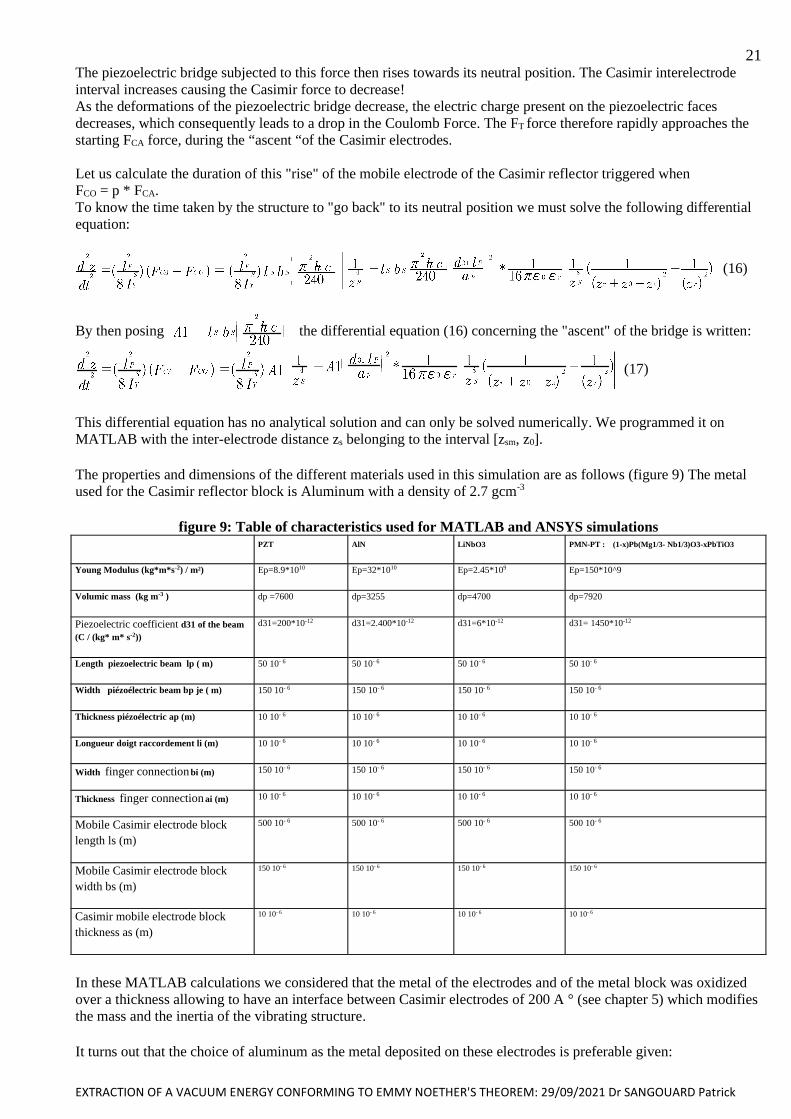
The properties and dimensions of the different materials used in this simulation are as follows (figure 9) The metal
used for the Casimir reflector block is Aluminum with a density of 2.7 gcm-3
figure 9: Table of characteristics used for MATLAB and ANSYS simulations PZT AlN LiNbO3 PMN-PT : (1-x)Pb(Mg1/3- Nb1/3)O3-xPbTiO3
Young Modulus (kg*m*s-2) / m²) Ep=8.9*1010 Ep=32*1010 Ep=2.45*109 Ep=150*10^9
Volumic mass (kg m-3 ) dp =7600 dp=3255 dp=4700 dp=7920
Piezoelectric coefficient d31 of the beam
(C / (kg* m* s-2))
d31=200*10-12 d31=2.400*10-12 d31=6*10-12 d31= 1450*10-12
Length piezoelectric beam lp ( m) 50 10- 6 50 10- 6 50 10- 6 50 10- 6
Width piézoélectric beam bp je ( m) 150 10- 6 150 10- 6 150 10- 6 150 10- 6
Thickness piézoélectric ap (m) 10 10- 6 10 10- 6 10 10- 6 10 10- 6
Longueur doigt raccordement li (m) 10 10- 6 10 10- 6 10 10- 6 10 10- 6
Width finger connection bi (m) 150 10- 6 150 10- 6 150 10- 6 150 10- 6
Thickness finger connection ai (m) 10 10- 6 10 10- 6 10 10- 6 10 10- 6
Mobile Casimir electrode block
length ls (m)
500 10- 6 500 10- 6 500 10- 6 500 10- 6
Mobile Casimir electrode block
width bs (m)
150 10- 6 150 10- 6 150 10- 6 150 10- 6
Casimir mobile electrode block
thickness as (m)
10 10- 6 10 10- 6 10 10- 6 10 10- 6
In these MATLAB calculations we considered that the metal of the electrodes and of the metal block was oxidized
over a thickness allowing to have an interface between Casimir electrodes of 200 A ° (see chapter 5) which modifies
the mass and the inertia of the vibrating structure.
It turns out that the choice of aluminum as the metal deposited on these electrodes is preferable given:

EXTRACTION OF A VACUUM ENERGY CONFORMING TO EMMY NOETHER'S THEOREM: 29/09/2021 Dr SANGOUARD Patrick
22 1 / the ratios between the thickness of the metal oxide obtained and that of the metal attacked by the growth of
this oxide during its thermal oxidation (see chapter V)
2 / with a view to increasing and optimizing the vibration frequency of the structure by minimizing the inertia of the
parallelepipedal block for transferring the Casimir force to the piezoelectric bridge and that the density of the
aluminum is weak.
The mass M of the vibrating structure is then:
M= dpm*(as*bs*ls + ai*bi*li) +dom * 2*zof*(aso*bso+bso*lso+aso*lso)+dp*(ap*bp*lp);
With dpm the density of the metal, as, bs, ls the geometries of the final metal part of the Casimir electrode sole, dom the
density of the metal oxide, aso, bso, lso the geometries of the oxidized parts around the 6 faces of the metal block, dp
the density of the piezoelectric parallelepiped (see figure 10):
Figure 10: Final structure with the metal oxides
surrounding the metal electrodes.
III .2 / Calculation of the current peak
Let us estimate the duration of the current peak linked to the circulation and homogenization on the return electrodes
of the mobile charges.
Let Rm be the ohmic resistance of the metals used for the surface electrodes Sp1 + the LIN solenoid + the Sr electrode
(see figure 5) and Cs the capacitance formed by the gap between the return electrodes Sp2 and Sr.
Then the current peak circulating during the transition of the mobile loads between Sp1 to SR via circuit n°1 and the
LIN solenoid is as we have already seen
The time t being counted from the closing of the MOSNE switch.
The duration of this current peak is estimated at te = Rm. Cs. Log (2) when the charges on each electrode will be
Qmn2 / 2. In this expression:
• Rm m * lm / Sm, with m the resistivity of the metallic conductor in the circuit between electrodes (the solenoid +
the electrodes themselves),
• lm its total length of this conductor, Sm its section
• Cs = 0. om.lp. bp / zr, the inter-electrode return capacitance, with 0 the permittivity of vacuum, 0m the relative
permittivity of the metal oxide, lp and bp the geometries of the return electrode.
A calculation of the duration of the homogenization of the electric charges and therefore of the duration of the
current peak (based on an estimate to propagate in a LIN coil of about 10-5 Henri) gives te 10-9 s.
EXTRACTION OF A VACUUM ENERGY CONFORMING TO EMMY NOETHER'S THEOREM: 29/09/2021 Dr SANGOUARD Patrick
23 This current peak passing through a LIN solenoid develops a voltage peak UIN = LIN IINP / te = LIN * Qmn2 /(2.te * Rm. Cs)
which will be exploited by an integrated electronics without any power supply described in chapter IV.
We present below the results of the MATLAB simulations carried out by numerically calculating the differential
equations (13) and (17). These numerical calculations give the vibration frequency of the structure which, as we will
see, vibrates at a frequency lower than its first resonant frequency (IV)
This vibration frequency depends on the characteristics of the structure (Nature of the piezoelectric material, nature
of the metallic conductors, initial interface z0 and zr between Casimir electrodes and return electrodes , geometric
dimensions of the Casimir reflectors, coefficient of proportionality p = FCO / FCA…)). (See IV and Annex)
IV/ SIMULATION OF DEVICES WITH DIFFERENTS PIEZOELECTRIC BRIDGE
We will see that this device vibrates at a frequency lower than its first resonant frequency and that its vibration
frequency depends on the characteristics of the structure (Nature of the piezoelectric material, nature of the metallic
conductors, starting interface z0 and zr between Casimir electrodes and return Coulomb electrodes , dimensions of
the Casimir reflectors, coefficient of proportionality p = FCO / FCA…).
Except precision the interface zr between the coulombs electrode is the same that those of Casimir reflector z0
IV- 1 / PIEZOELECTRIC MATERIALS = PZT (Lead Zirconia Titanium)
IV-1-1 / interface between Casimir electrodes as a function of time for different trigger values of MOS transistors
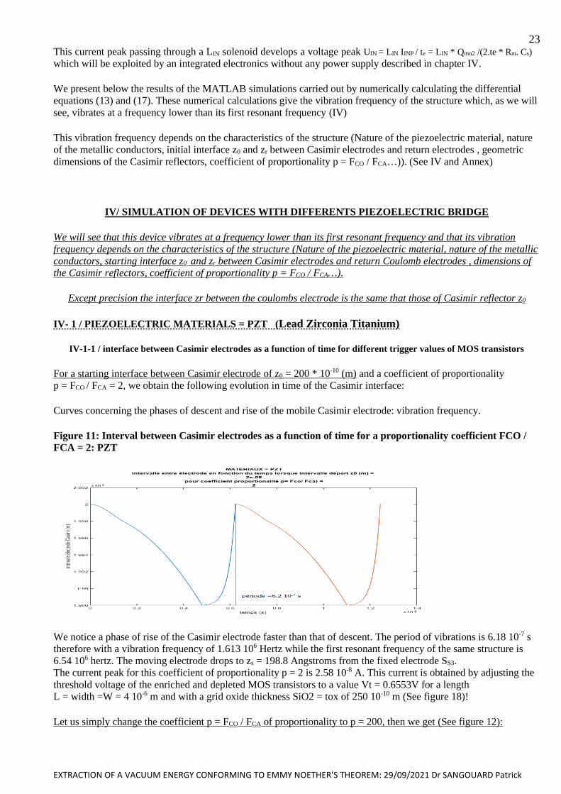
For a starting interface between Casimir electrode of z0 = 200 * 10-10 (m) and a coefficient of proportionality
p = FCO / FCA = 2, we obtain the following evolution in time of the Casimir interface:
Curves concerning the phases of descent and rise of the mobile Casimir electrode: vibration frequency.
Figure 11: Interval between Casimir electrodes as a function of time for a proportionality coefficient FCO /
FCA = 2: PZT
We notice a phase of rise of the Casimir electrode faster than that of descent. The period of vibrations is 6.18 10-7 s
therefore with a vibration frequency of 1.613 106 Hertz while the first resonant frequency of the same structure is
6.54 106 hertz. The moving electrode drops to zs = 198.8 Angstroms from the fixed electrode SS3.
The current peak for this coefficient of proportionality p = 2 is 2.58 10-8 A. This current is obtained by adjusting the
threshold voltage of the enriched and depleted MOS transistors to a value Vt = 0.6553V for a length
L = width =W = 4 10-6 m and with a grid oxide thickness SiO2 = tox of 250 10-10 m (See figure 18)!
Let us simply change the coefficient p = FCO / FCA of proportionality to p = 200, then we get (See figure 12):
EXTRACTION OF A VACUUM ENERGY CONFORMING TO EMMY NOETHER'S THEOREM: 29/09/2021 Dr SANGOUARD Patrick
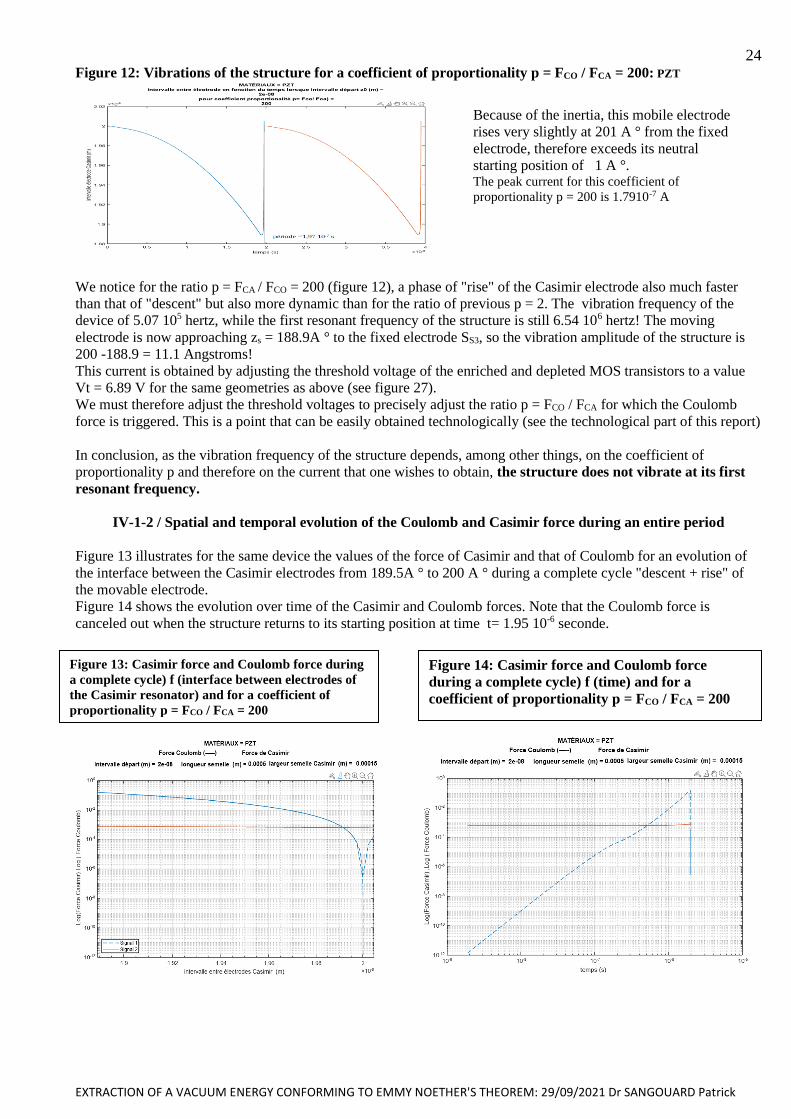
24 Figure 12: Vibrations of the structure for a coefficient of proportionality p = FCO / FCA = 200: PZT
We notice for the ratio p = FCA / FCO = 200 (figure 12), a phase of "rise" of the Casimir electrode also much faster
than that of "descent" but also more dynamic than for the ratio of previous p = 2. The vibration frequency of the
device of 5.07 105 hertz, while the first resonant frequency of the structure is still 6.54 106 hertz! The moving
electrode is now approaching zs = 188.9A ° to the fixed electrode SS3, so the vibration amplitude of the structure is
200 -188.9 = 11.1 Angstroms! This current is obtained by adjusting the threshold voltage of the enriched and depleted MOS transistors to a value
Vt = 6.89 V for the same geometries as above (see figure 27).
We must therefore adjust the threshold voltages to precisely adjust the ratio p = FCO / FCA for which the Coulomb
force is triggered. This is a point that can be easily obtained technologically (see the technological part of this report)
In conclusion, as the vibration frequency of the structure depends, among other things, on the coefficient of
proportionality p and therefore on the current that one wishes to obtain, the structure does not vibrate at its first
resonant frequency.
IV-1-2 / Spatial and temporal evolution of the Coulomb and Casimir force during an entire period
Figure 13 illustrates for the same device the values of the force of Casimir and that of Coulomb for an evolution of
the interface between the Casimir electrodes from 189.5A ° to 200 A ° during a complete cycle "descent + rise" of
the movable electrode.
Figure 14 shows the evolution over time of the Casimir and Coulomb forces. Note that the Coulomb force is
canceled out when the structure returns to its starting position at time t= 1.95 10-6 seconde.
The Figure 36 shows the ratio p = FCO / FCA
during a complete structural vibration cycle
Figure 13: Casimir force and Coulomb force during
a complete cycle) f (interface between electrodes of
the Casimir resonator) and for a coefficient of
proportionality p = FCO / FCA = 200
Figure 14: Casimir force and Coulomb force
during a complete cycle) f (time) and for a
coefficient of proportionality p = FCO / FCA = 200
Because of the inertia, this mobile electrode
rises very slightly at 201 A ° from the fixed
electrode, therefore exceeds its neutral
starting position of 1 A °. The peak current for this coefficient of
proportionality p = 200 is 1.7910-7 A
EXTRACTION OF A VACUUM ENERGY CONFORMING TO EMMY NOETHER'S THEOREM: 29/09/2021 Dr SANGOUARD Patrick
25 Figure 15 shows the ratio p = FCO / FCA = f(time) during a complete structural vibration cycle and with a choice of
maximum ratio = 200
IV-1-3 / Variation of the starting interface z0 between Casimir electrodes: PZT
Figure 16: Maximum Peak CURRENT = f (starting interface z0), Maximum selected FCO / FCA p ratio = 200
If Qp = charge on the piezoelectric bridge just before the triggering of the MOS switches and te = Rm * Cs * ln (2) 10-9
the transition period of these charges during their homogenization on the 2 return electrodes, then the peak of
current is approximated with Is = Qp / (2 * te). This current peak is present even if the transistors may close some
time after its existence because the mobile charges have already propagated.
We notice (Figure 17) that the vibration frequency of the structure drops as the initial space between the Casimir
electrodes increases, which is related to a decrease in the Casimir Force and therefore makes sense. The vibration
frequency depends on the chosen FCO / FCA ratio. This frequency drops and stabilizes around 2.6 MHz as the
electrode interface increases by a ratio of 200. It is much lower than the first resonant frequency of the structure
which is 6.85 Megahertz (for this structure). The vibration frequency approaches that of first resonance if the starting
z0 interface is less than 200 Angstroms.
We chose an initial interface of 200 A ° for reasons of technological feasibility (see VI)!
Figure 15 shows the ratio p = FCO / FCA between
the Coulomb force and that of Casimir during a
complete structural vibration cycle. We notice
that this ratio reaches the chosen ratio of 200 at
time 1.95 * 10-6 seconds then plunges to zero
during the "rise" of the structure.
Note that to have a significant current it is
necessary to use starting interfaces between
Casimir electrodes of low values and less than
300 Angstroms. This weak interface is difficult
to obtain but remains possible with a technology
that we offer (see technology chapter).
Figure 17: Structure vibration frequency = f
(starting interface z0): Fco / Fca chosen = 200:
PZT
Figure 18: MOS threshold voltage = f (starting
interface z0): Fco / Fca chosen = 200: PZT
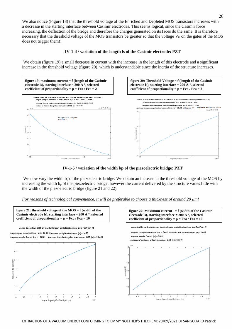
EXTRACTION OF A VACUUM ENERGY CONFORMING TO EMMY NOETHER'S THEOREM: 29/09/2021 Dr SANGOUARD Patrick
26 We also notice (Figure 18) that the threshold voltage of the Enriched and Depleted MOS transistors increases with
a decrease in the starting interface between Casimir electrodes. This seems logical, since the Casimir force
increasing, the deflection of the bridge and therefore the charges generated on its faces do the same. It is therefore
necessary that the threshold voltage of the MOS transistors be greater so that the voltage VG on the gates of the MOS
does not trigger them!!
IV-1-4 / variation of the length ls of the Casimir electrode: PZT
We obtain (figure 19) a small decrease in current with the increase in the length of this electrode and a significant
increase in the threshold voltage (figure 20), which is understandable since the inertia of the structure increases.
IV-1-5 / variation of the width bp of the piezoelectric bridge: PZT
We now vary the width bp of the piezoelectric bridge. We obtain an increase in the threshold voltage of the MOS by
increasing the width bp of the piezoelectric bridge, however the current delivered by the structure varies little with
the width of the piezoelectric bridge (figure 21 and 22).
For reasons of technological convenience, it will be preferable to choose a thickness of around 20 m!
figure 19: maximum current = f (length of the Casimir
electrode ls), starting interface = 200 A °, selected
coefficient of proportionality = p = Fco / Fca = 2
figure 20: Threshold Voltage = f (length of the Casimir
electrode ls), starting interface = 200 A °, selected
coefficient of proportionality = p = Fco / Fca = 2
figure 21: threshold voltage of the MOS = f (width of the
Casimir electrode ls), starting interface = 200 A °, selected
coefficient of proportionality = p = Fco / Fca = 10
figure 22: Maximum current = f (width of the Casimir
electrode ls), starting interface = 200 A °, selected
coefficient of proportionality = p = Fco / Fca = 10

EXTRACTION OF A VACUUM ENERGY CONFORMING TO EMMY NOETHER'S THEOREM: 29/09/2021 Dr SANGOUARD Patrick
27
IV-1-6 / variation of the thickness ap of the piezoelectric bridge: PZT
If we increase the thickness ap of the piezoelectric bridge, we obtain a decrease in the current (figure 23) and the
threshold voltage of the MOS (figure 24) but an increase in the vibration frequency (figure 25)
IV-1-7 / variation of the proportionality ratio p = FCO / FCA: PZT
In a non-intuitive way, the current simply increases linearly by a factor of 40 (figure 26) if we increase the
proportionality ratio p = FCO / FCA by a factor of 500. On the other hand, the threshold voltage of the MOS switches
increases by a factor 8 for the same variation of the interface (figure 27). The MOS N or P switch transistors
enriched in parallel have the following geometries: Width W = 4 m and length L = 4 m
Figure 24 ; Threshold of the MOS = f( Thickness
of piezoelectric film ), start Interface = 200 A°
with a choice Fco/Fca =10
Figure 23 ; courant of the MOS = f( Thickness
of piezoelectric film ), start Interface = 200 A°
with a choice Fco/Fca =10
Figure 25: Structure vibration frequency as a function of the thickness ap of the
piezoelectric bridge, starting interface z0 to 200 A °, Ratio p = FCO / FCA = 10

EXTRACTION OF A VACUUM ENERGY CONFORMING TO EMMY NOETHER'S THEOREM: 29/09/2021 Dr SANGOUARD Patrick
28
IV-2 / USE OF OTHER PIEZOELECTRIC MATERIALS
In the presentation above we used PZT but , in order to increase the density of electric charges at the terminals of the
piezoelectric bridge, piezoelectric material PMN-PT can be used which can be deposited by RF-magnetron
sputtering and of composition , for example : PMN-PT= (1-x) Pb (Mg1 / 3 - Nb1 / 3) O3-xPbTiO3;
d31 = 1450 * 10-12 C / (kg * m * s-2) and a Young's modulus of Ep = 150 * 109 (Figure 9).
We will also simulate the results obtained with AlN (Aluminum nitride), another piezoelectric material or AlN
widely used in microelectronics because it is easily removable and lead-free!
IV-2-1 / Piezoelectric material = PMN-PT
With the MATLAB simulation of a structure using PMN-Pt we obtain the evolution over time of the Casimir and
Coulomb forces as well as the FCO / FCA ratio of figures 28 to 41 below. For a ratio of 1000, the maximum current
delivered by the vibrating structure , the threshold voltage of the MOSE and MOSD and the vibration frequency of
the structure are respectively: 1.2 10-4 A, Vt = 3.2 V and 957000 Hertz
IV-2-1-1 / Evolution of the Casimir interface as a function of time during two periods: PMN-PT
Figure 26 ; current of the MOS = f( ratio = Fco/Fca ), start
Interface = 200 A° piezoelectric material = PZT
Figure 27 ; Threshold voltage of the MOS = f( ratio =
Fco/Fca ), start Interface = 200 A° piezoelectric material =
PZT
Figure 28: plot of the evolution of the Casimir inter-electrode interval as a function of time over two periods and an
Fco / Fca Ratio = 10000: Casimir inter-electrode interface = 200 A°

EXTRACTION OF A VACUUM ENERGY CONFORMING TO EMMY NOETHER'S THEOREM: 29/09/2021 Dr SANGOUARD Patrick
29 The FCO / FCA ratio = 10000 induces a period of 3.85 10-6 s and a rise time of 21.3 10-9 s with a deflection of the
bridge of 105 A °. The structure vibrates at 259.7 kHz. At the rise sequence , the structure exceeds the initial 200 A °
by 20 A ° due to inertia (Fig 28).
For p=1000, we notice a vibration amplitude of 50A ° with a period of 2.96 10-6 s, with faster rise of the mobile
electrode producing a slight rebound of 5A, because of the inertia of the structure (Figure 29).
For the ratio FCO / FCA = 2 (figure 30) a vibration amplitude of just 0.27 A ° and a period of 1.8610-7 s is obtained
This low deformation of the PMN-PT piezoelectric bridge is mainly due to the extremely high piezoelectric
coefficient d31 of 1450 (pC/N) of PMN-PT compared to 120 (pC/N) for PZT (figures 9).
It is also observed that weak overshoot of the initial interface (200 A °) for the mobile electrode increases with the
ratio (FCO / FCA)
IV-2-1-2 / Evolution of the forces of Casimir and Coulomb: PMN-PT
We obtain the evolution of the Casimir and Coulomb forces as a function of the inter-electrode interface (figure 31)
and over time (figure 32) as well as the FCO / FCA ratio as a function of time for an entire period (figures 33)
Figure 31: Materials = PMN-PT: Coulomb and
Casimir force as a function of the inter-electrode
interface. Starting interface = 200A °
Figure 32: Materials = PMN-PT: Coulomb and
Casimir force as a function of time. Starting
interface = 200A °
Figure 29: plot of the evolution of the Casimir inter-electrode
interval as a function of time over two periods and an Fco / Fca
Ratio = 1000: Casimir inter-electrode interface = 200 A°
Figure 30: plot of the evolution of the Casimir inter-
electrode interval as a function of time over two
periods and a Ratio Fco / Fca = 2. Casimir inter-
electrode interface = 200 A °
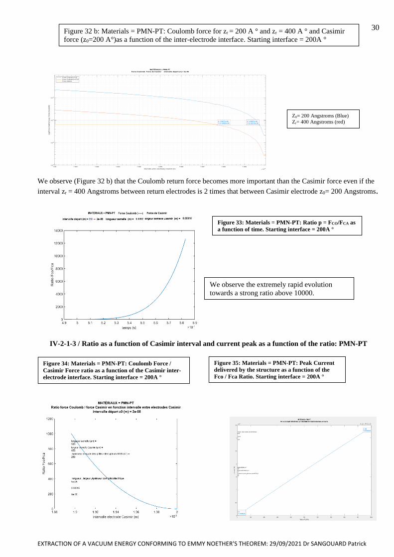
EXTRACTION OF A VACUUM ENERGY CONFORMING TO EMMY NOETHER'S THEOREM: 29/09/2021 Dr SANGOUARD Patrick
30
Z0= 200 Angstroms (Blue)
Zr= 400 Angstroms (red)
We observe (Figure 32 b) that the Coulomb return force becomes more important than the Casimir force even if the
interval zr = 400 Angstroms between return electrodes is 2 times that between Casimir electrode z0= 200 Angstroms.
IV-2-1-3 / Ratio as a function of Casimir interval and current peak as a function of the ratio: PMN-PT
Figure 34: Materials = PMN-PT: Coulomb Force /
Casimir Force ratio as a function of the Casimir inter-
electrode interface. Starting interface = 200A °
Figure 35: Materials = PMN-PT: Peak Current
delivered by the structure as a function of the
Fco / Fca Ratio. Starting interface = 200A °
Figure 33: Materials = PMN-PT: Ratio p = FCO/FCA as
a function of time. Starting interface = 200A °
We observe the extremely rapid evolution
towards a strong ratio above 10000.
Figure 32 b: Materials = PMN-PT: Coulomb force for zr = 200 A ° and zr = 400 A ° and Casimir
force (z0=200 A°)as a function of the inter-electrode interface. Starting interface = 200A °

EXTRACTION OF A VACUUM ENERGY CONFORMING TO EMMY NOETHER'S THEOREM: 29/09/2021 Dr SANGOUARD Patrick
31 We observe (Fig 34 and 35) that for PMN-PT a deflection of 10 A ° and a length of the piezoelectric bridge of
150m of the mobile Casimir electrode is sufficient to have an Fco / Fca ratio = 1000. A Ratio of 2 gives a peak
current of 7 10-7 A, while a ratio of 1000 produces a peak current of about 3.5 10-4 A (Fig 35) for the same period of
homogenization of the charges of about 10-9 s!
IV-2-1-4 / peak current as a function of time and peak voltage across the coil for 2 periods: PMN-PT
The following figures illustrate the current peak generated by the automatic vibrating structure with an inserted
magnification showing the shape of this peak as a function of time (figure 36) and its exponentially decrease during
about 10-9 s. This current of about 3.5 10-4 A flowing through an inductor LIN of 4 10-5 Henri naturally generates a
voltage of 4 Volts (figure 37)
The current peak that appears with each cycle of vibration is due to the homogenization of the electrical charges on
the two parts of the return electrode. This current peak follows the equation
with Qmn2 = d31lp FCA/ (2 * ap).
This charge transferred from the electrode on face 1 of the piezoelectric bridge to the return electrode which is
initially grounded does not depend on the common width bp = bs = bi of the structures.
Figure 36: Materials = PMN-PT: Current peak as a function of time obtained over 2 cycles. Starting interface = 200A °
Ratio p=Fco /Fca=1000
Figure 37: Materials = PMN-PT: Voltage peak across the 4 * 10-5 H solenoid as a function of the time
obtained over 2 cycles. Starting interface = 200A ° , Ratio p=Fco /Fca=1000
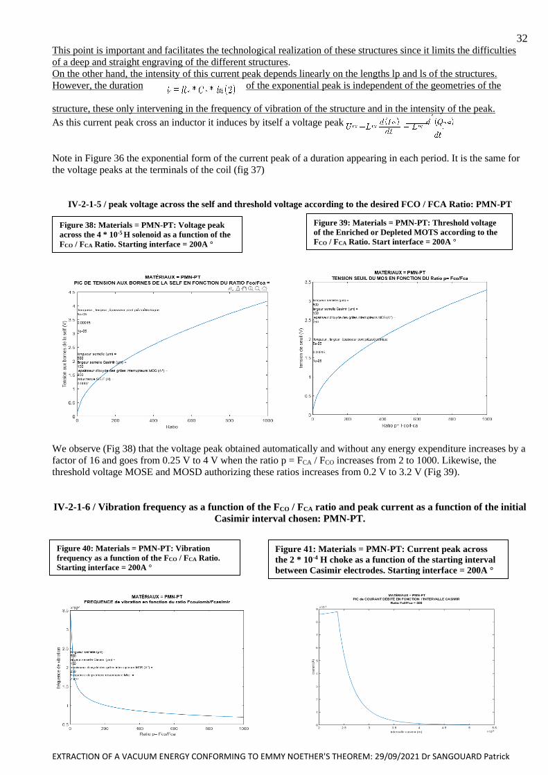
EXTRACTION OF A VACUUM ENERGY CONFORMING TO EMMY NOETHER'S THEOREM: 29/09/2021 Dr SANGOUARD Patrick
32 This point is important and facilitates the technological realization of these structures since it limits the difficulties
of a deep and straight engraving of the different structures.
On the other hand, the intensity of this current peak depends linearly on the lengths lp and ls of the structures.
However, the duration of the exponential peak is independent of the geometries of the
structure, these only intervening in the frequency of vibration of the structure and in the intensity of the peak.
As this current peak cross an inductor it induces by itself a voltage peak
Note in Figure 36 the exponential form of the current peak of a duration appearing in each period. It is the same for
the voltage peaks at the terminals of the coil (fig 37)
IV-2-1-5 / peak voltage across the self and threshold voltage according to the desired FCO / FCA Ratio: PMN-PT
We observe (Fig 38) that the voltage peak obtained automatically and without any energy expenditure increases by a
factor of 16 and goes from 0.25 V to 4 V when the ratio p = FCA / FCO increases from 2 to 1000. Likewise, the
threshold voltage MOSE and MOSD authorizing these ratios increases from 0.2 V to 3.2 V (Fig 39).
IV-2-1-6 / Vibration frequency as a function of the FCO / FCA ratio and peak current as a function of the initial
Casimir interval chosen: PMN-PT.
Figure 38: Materials = PMN-PT: Voltage peak
across the 4 * 10-5 H solenoid as a function of the
FCO / FCA Ratio. Starting interface = 200A °
Figure 39: Materials = PMN-PT: Threshold voltage
of the Enriched or Depleted MOTS according to the
FCO / FCA Ratio. Start interface = 200A °
Figure 40: Materials = PMN-PT: Vibration
frequency as a function of the FCO / FCA Ratio.
Starting interface = 200A °
Figure 41: Materials = PMN-PT: Current peak across
the 2 * 10-4 H choke as a function of the starting interval
between Casimir electrodes. Starting interface = 200A °
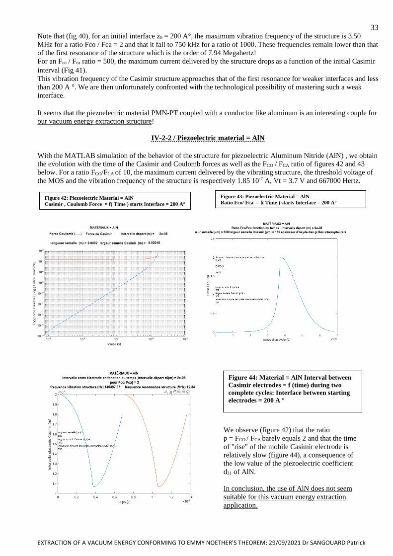
EXTRACTION OF A VACUUM ENERGY CONFORMING TO EMMY NOETHER'S THEOREM: 29/09/2021 Dr SANGOUARD Patrick
33 Note that (fig 40), for an initial interface z0 = 200 A°, the maximum vibration frequency of the structure is 3.50
MHz for a ratio Fco / Fca = 2 and that it fall to 750 kHz for a ratio of 1000. These frequencies remain lower than that
of the first resonance of the structure which is the order of 7.94 Megahertz!
For an Fco / Fca ratio = 500, the maximum current delivered by the structure drops as a function of the initial Casimir
interval (Fig 41). This vibration frequency of the Casimir structure approaches that of the first resonance for weaker interfaces and less
than 200 A °. We are then unfortunately confronted with the technological possibility of mastering such a weak
interface. It seems that the piezoelectric material PMN-PT coupled with a conductor like aluminum is an interesting couple for
our vacuum energy extraction structure!
IV-2-2 / Piezoelectric material = AlN
With the MATLAB simulation of the behavior of the structure for piezoelectric Aluminum Nitride (AlN) , we obtain
the evolution with the time of the Casimir and Coulomb forces as well as the FCO / FCA ratio of figures 42 and 43
below. For a ratio FCO/FCA of 10, the maximum current delivered by the vibrating structure, the threshold voltage of
the MOS and the vibration frequency of the structure is respectively 1.85 10-7 A, Vt = 3.7 V and 667000 Hertz.
Figure 42: Piezoelectric Material = AlN
Casimir , Coulomb Force = f( Time ) starts Interface = 200 A°
Figure 43: Piezoelectric Material = AlN
Ratio Fco/ Fca = f( Time ) starts Interface = 200 A°
Figure 44: Material = AlN Interval between
Casimir electrodes = f (time) during two
complete cycles: Interface between starting
electrodes = 200 A °
We observe (figure 42) that the ratio
p = FCO / FCA barely equals 2 and that the time
of "rise" of the mobile Casimir electrode is
relatively slow (figure 44), a consequence of
the low value of the piezoelectric coefficient
d31 of AlN.
In conclusion, the use of AlN does not seem
suitable for this vacuum energy extraction
application.
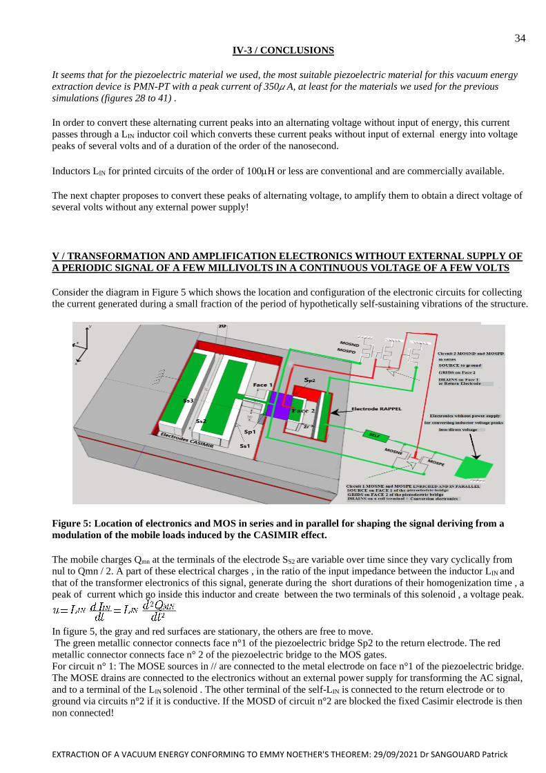
EXTRACTION OF A VACUUM ENERGY CONFORMING TO EMMY NOETHER'S THEOREM: 29/09/2021 Dr SANGOUARD Patrick
34 IV-3 / CONCLUSIONS
It seems that for the piezoelectric material we used, the most suitable piezoelectric material for this vacuum energy
extraction device is PMN-PT with a peak current of 350 A, at least for the materials we used for the previous
simulations (figures 28 to 41) .
In order to convert these alternating current peaks into an alternating voltage without input of energy, this current
passes through a LIN inductor coil which converts these current peaks without input of external energy into voltage
peaks of several volts and of a duration of the order of the nanosecond.
Inductors LIN for printed circuits of the order of 100H or less are conventional and are commercially available.
The next chapter proposes to convert these peaks of alternating voltage, to amplify them to obtain a direct voltage of
several volts without any external power supply!
V / TRANSFORMATION AND AMPLIFICATION ELECTRONICS WITHOUT EXTERNAL SUPPLY OF
A PERIODIC SIGNAL OF A FEW MILLIVOLTS IN A CONTINUOUS VOLTAGE OF A FEW VOLTS
Consider the diagram in Figure 5 which shows the location and configuration of the electronic circuits for collecting
the current generated during a small fraction of the period of hypothetically self-sustaining vibrations of the structure.
Figure 5: Location of electronics and MOS in series and in parallel for shaping the signal deriving from a
modulation of the mobile loads induced by the CASIMIR effect.
The mobile charges Qmn at the terminals of the electrode SS2 are variable over time since they vary cyclically from
nul to Qmn / 2. A part of these electrical charges , in the ratio of the input impedance between the inductor LIN and
that of the transformer electronics of this signal, generate during the short durations of their homogenization time , a
peak of current which go inside this inductor and create between the two terminals of this solenoid , a voltage peak.
In figure 5, the gray and red surfaces are stationary, the others are free to move.
The green metallic connector connects face n°1 of the piezoelectric bridge Sp2 to the return electrode. The red
metallic connector connects face n° 2 of the piezoelectric bridge to the MOS gates.
For circuit n° 1: The MOSE sources in // are connected to the metal electrode on face n°1 of the piezoelectric bridge.
The MOSE drains are connected to the electronics without an external power supply for transforming the AC signal,
and to a terminal of the LIN solenoid . The other terminal of the self-LIN is connected to the return electrode or to
ground via circuits n°2 if it is conductive. If the MOSD of circuit n°2 are blocked the fixed Casimir electrode is then
non connected!

EXTRACTION OF A VACUUM ENERGY CONFORMING TO EMMY NOETHER'S THEOREM: 29/09/2021 Dr SANGOUARD Patrick
35 The enriched MOSNE and MOSPE of circuit n°1 then connect face 1 to the return electrode via the self LIN, and
this when their gates have a voltage making one of them ON. During this period the circuit composed of MOSND
and MOSPD of circuit n°2 is then blocked.
Likewise, when circuit n°1 is blocked, then circuit n°2 is conducting and connects the return electrode to ground,
which eliminates the charges present on this electrode and then prevents any electrostatic attraction.
We will describe these electronics designed and successfully tested at ESIEE with SPICE when I was studying
abandoned sensors. This electronic gave very encouraging SPICE simulation results and was presented succinctly in
various conferences but was never produced ... for lack of financial means!
In these SPICE simulations, the micro transformer was assimilated to a voltage source delivering a power U * I
limited to a few nW (voltages of a few mV and current much lower than the microampere).
The LIN self plays the same role as this micro transformer since it delivers a voltage during current variation
generated during vibrations!
Now retired and no longer having sufficient means of simulations, I am simply describing the results of the SPICE
simulations obtained in 2008. Because it seems that these electronics would correspond quite well to the
modification without external energy of the alternating and small signals in an exploitable direct voltage.
The principle used to amplify and transform a weak signal without power supply derives from that well known of
the diode bridge rectifier of Graetz or the doubler of Schenkel and Marius Latour
The crippling problem with this type of rectifier is that the diodes of these rectifiers are conductive only with a
minimum voltage of around 0.6 V at their terminals.
As the alternating signal from the vacuum energy extraction device can be weaker, it is necessary to have switches
that are triggered with a lower control voltage and ideally zero.
The principle diagram of this electronics is presented in figure (45)
figure 45 Principle of electronics for amplifying and rectifying a weak AC signal
The MOSE N and P transistors of this rectifier circuit must have a technologically defined threshold voltage at a
value as close as possible to zero.
The precision of nullity of these threshold voltages will depend on the values of alternating voltages at the terminals
of the inductor LIN, therefore on the second derivative of the temporal variations of the charges appearing on Sp2
during the time of their homogenization which is of the order of te = Rm . Cs . Log (2)
In this circuit of figure 45 the self LIN was replaced by a micro transformer, but this self LIN plays the same role as
this micro transformer since it delivers a limited power U.I
The left part of the micro-transformer takes care of the negative voltages of the input signal, while the right part
takes care of the positive voltages. The circuit is composed of several stages without no power supply which rectify
and amplify, on the one hand the negative parts of the weak input signal and on the other hand the positive parts .
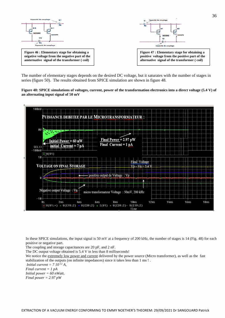
EXTRACTION OF A VACUUM ENERGY CONFORMING TO EMMY NOETHER'S THEOREM: 29/09/2021 Dr SANGOUARD Patrick
36
The number of elementary stages depends on the desired DC voltage, but it saturates with the number of stages in
series (figure 50). The results obtained from SPICE simulation are shown in figure 48.
Figure 48: SPICE simulations of voltages, current, power of the transformation electronics into a direct voltage (5.4 V) of
an alternating input signal of 50 mV
In these SPICE simulations, the input signal is 50 mV at a frequency of 200 kHz, the number of stages is 14 (Fig. 48) for each
positive or negative part.
The coupling and storage capacitances are 20 pF, and 2 nF.
The DC output voltage obtained is 5.4 V in less than 8 milliseconds!
We notice the extremely low power and current delivered by the power source (Micro transformer), as well as the fast
stabilization of the outputs (on infinite impedances) since it takes less than 1 ms ! .
Initial current = 7 10-12 A,
Final current = 1 pA
Initial power = 60 nWatt,
Final power = 2.97 pW
Figure 46 : Elementary stage for obtaining a
négative voltage from the negative part of the
amternative signal of the transformer ( coil)
Figure 47 : Elementary stage for obtaining a
positive voltage from the positive part of the
alternative signal of the transformer ( coil)
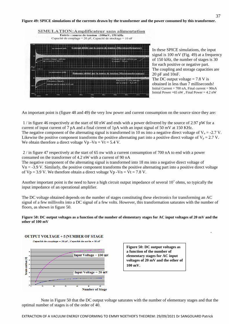
EXTRACTION OF A VACUUM ENERGY CONFORMING TO EMMY NOETHER'S THEOREM: 29/09/2021 Dr SANGOUARD Patrick
37
Tension sortie positive : Vp
Figure 49: SPICE simulations of the currents drawn by the transformer and the power consumed by this transformer.
An important point is (figure 48 and 49) the very low power and current consumption on the source since they are:
1 / in figure 46 respectively at the start of 60 nW and ends with a power delivered by the source of 2.97 pW for a
current of input current of 7 pA and a final cirrent of 1pA with an input signal of 50 mV at 150 KHz.
The negative component of the alternating signal is transformed in 10 ns into a negative direct voltage of Vn = -2.7 V.
Likewise the positive component transforms the positive alternating part into a positive direct voltage of Vp = 2.7 V.
We obtain therefore a direct voltage Vp -Vn = Vt = 5.4 V.
2 / in figure 47 respectively at the start of 65 nw with a current consumption of 700 nA to end with a power
consumed on the transformer of 4.2 nW with a current of 90 nA
The negative component of the alternating signal is transformed into 18 ms into a negative direct voltage of
Vn = -3.9 V. Similarly, the positive component transforms the positive alternating part into a positive direct voltage
of Vp = 3.9 V. We therefore obtain a direct voltage Vp -Vn = Vt = 7.8 V.
Another important point is the need to have a high circuit output impedance of several 107 ohms, so typically the
input impedance of an operational amplifier.
The DC voltage obtained depends on the number of stages constituting these electronics for transforming an AC
signal of a few millivolts into a DC signal of a few volts. However, this transformation saturates with the number of
floors, as shown in figure 50.
Figure 50: DC output voltages as a function of the number of elementary stages for AC input voltages of 20 mV and the
other of 100 mV
.
Note in Figure 50 that the DC output voltage saturates with the number of elementary stages and that the
optimal number of stages is of the order of 40.
In these SPICE simulations, the input
signal is 100 mV (Fig. 49) at a frequency
of 150 kHz, the number of stages is 30
for each positive or negative part.
The coupling and storage capacities are
20 pF and 10nF.
The DC output voltage = 7.8 V is
obtained in less than 7 milliseconds! Initial Current = 700 nA, Final current = 90nA
Ininial Power =65 nW , Final Power = 4.2 nW
Figure 50: DC output voltages as
a function of the number of
elementary stages for AC input
voltages of 20 mV and the other of
100 mV.
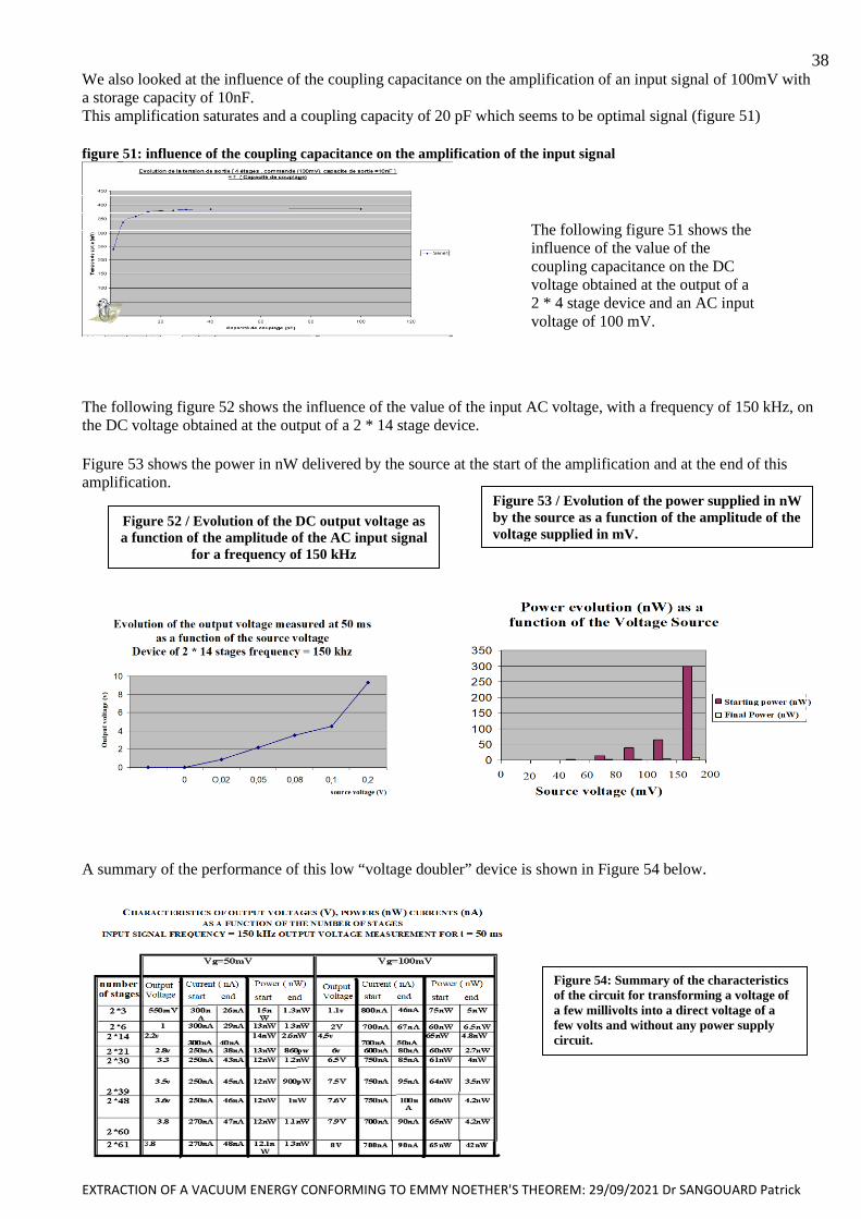
EXTRACTION OF A VACUUM ENERGY CONFORMING TO EMMY NOETHER'S THEOREM: 29/09/2021 Dr SANGOUARD Patrick
38 We also looked at the influence of the coupling capacitance on the amplification of an input signal of 100mV with
a storage capacity of 10nF.
This amplification saturates and a coupling capacity of 20 pF which seems to be optimal signal (figure 51)
figure 51: influence of the coupling capacitance on the amplification of the input signal
The following figure 52 shows the influence of the value of the input AC voltage, with a frequency of 150 kHz, on
the DC voltage obtained at the output of a 2 * 14 stage device.
Figure 53 shows the power in nW delivered by the source at the start of the amplification and at the end of this
amplification.
A summary of the performance of this low “voltage doubler” device is shown in Figure 54 below.
Figure 54: Summary of the characteristics
of the circuit for transforming a voltage of
a few millivolts into a direct voltage of a
few volts and without any power supply
circuit.
The following figure 51 shows the
influence of the value of the
coupling capacitance on the DC
voltage obtained at the output of a
2 * 4 stage device and an AC input
voltage of 100 mV.
Figure 52 / Evolution of the DC output voltage as
a function of the amplitude of the AC input signal
for a frequency of 150 kHz
Figure 53 / Evolution of the power supplied in nW
by the source as a function of the amplitude of the
voltage supplied in mV.
with 2 * 14 stages and a frequency of 150 kHz
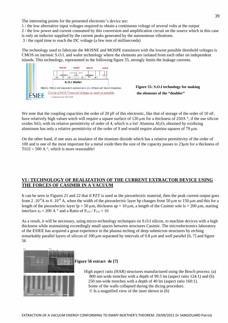
EXTRACTION OF A VACUUM ENERGY CONFORMING TO EMMY NOETHER'S THEOREM: 29/09/2021 Dr SANGOUARD Patrick
39 The interesting points for the presented electronic’s device are:
1 / the low alternative input voltages required to obtain a continuous voltage of several volts at the output
2 / the low power and current consumed by this conversion and amplification circuit on the source which in this case
is only an inductor supplied by the current peaks generated by the autonomous vibrations.
3 / the rapid time to reach the DC voltage (a few tens of milliseconds)
The technology used to fabricate the MOSNE and MOSPE transistors with the lowest possible threshold voltages is
CMOS on intrinsic S.O.I. and wafer technology where the elements are isolated from each other on independent
islands. This technology, represented in the following figure 55, strongly limits the leakage currents.
Figure 55: S.O.I technology for making
the elements of the “doubler”
We note that the coupling capacities the order of 20 pF of this electronic, like that of storage of the order of 10 nF,
have relatively high values witch will require a square surface of 120 m for a thickness of 250A °, if the use silicon
oxides SiO2 with its relative permittivity of order of 4, which is a lot! Alumina Al2O3 obtained by oxidizing
aluminum has only a relative permittivity of the order of 9 and would require alumina squares of 79 m.
On the other hand, if one uses as insulator of the titanium dioxide which has a relative permittivity of the order of
100 and is one of the most important for a metal oxide then the size of the capacity passes to 23m for a thickness of
TiO2 = 500 A °, which is more reasonable!
VI / TECHNOLOGY OF REALIZATION OF THE CURRENT EXTRACTOR DEVICE USING
THE FORCES OF CASIMIR IN A VACUUM
It can be seen in Figures 21 and 22 that if PZT is used as the piezoelectric material, then the peak current output goes
from 2 .10-8A to 6 .10-8 A, when the width of the piezoelectric layer bp changes from 50 m to 150 m and this for a
length of the piezoelectric layer lp = 50 m, thickness ap = 10 m, a length of the Casimir sole ls = 200 m, starting
interface z0 = 200 A ° and a Ratio of FCO / FCA = 10
As a result, it will be necessary, using micro-technology techniques on S.O.I silicon, to machine devices with a high
thickness while maintaining exceedingly small spaces between structures Casimir. The microelectronics laboratory
of the ESIEE has acquired a great experience in the plasma etching of deep submicron structures by etching
remarkably parallel layers of silicon of 100 m separated by intervals of 0.8 m and well parallel [6, 7] and figure
56
Figure 56 extract de [7]
High aspect ratio (HAR) structures manufactured using the Bosch process: (a)
800 nm-wide trenches with a depth of 99.5 lm (aspect ratio 124:1) and (b)
250 nm-wide trenches with a depth of 40 lm (aspect ratio 160:1).
Some of the walls collapsed during the dicing procedure.
© Is a magnified view of the inset shown in (b)
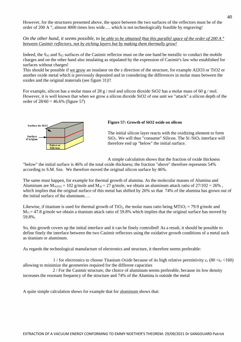
EXTRACTION OF A VACUUM ENERGY CONFORMING TO EMMY NOETHER'S THEOREM: 29/09/2021 Dr SANGOUARD Patrick
40 However, for the structures presented above, the space between the two surfaces of the reflectors must be of the
order of 200 A °, almost 4000 times less wide…. which is not technologically feasible by engraving!
On the other hand, it seems possible, to be able to be obtained that this parallel space of the order of 200 A °
between Casimir reflectors, not by etching layers but by making them thermally grow!
Indeed, the SS3 and SS2 surfaces of the Casimir reflector must on the one hand be metallic to conduct the mobile
charges and on the other hand also insulating as stipulated by the expression of Casimir's law who established for
surfaces without charges!
This should be possible if we grow an insulator on the z direction of the structure, for example Al2O3 or TiO2 or
another oxide metal which is previously deposited and in considering the differences in molar mass between the
oxides and the original materials (see figure 31)!!
For example, silicon has a molar mass of 28 g / mol and silicon dioxide SiO2 has a molar mass of 60 g / mol.
However, it is well known that when we grow a silicon dioxide SiO2 of one unit we "attack" a silicon depth of the
order of 28/60 = 46.6% (figure 57)
Figure 57: Growth of SiO2 oxide on silicon
The initial silicon layer reacts with the oxidizing element to form
SiO2. We will thus "consume" Silicon. The Si /SiO2 interface will
therefore end up "below" the initial surface.
A simple calculation shows that the fraction of oxide thickness
"below" the initial surface is 46% of the total oxide thickness; the fraction "above" therefore represents 54%
according to S.M. Sze. We therefore moved the original silicon surface by 46%.
The same must happen, for example for thermal growth of alumina. As the molecular masses of Alumina and
Aluminum are MAl2O3 = 102 g/mole and MAl = 27 g/mole, we obtain an aluminum attack ratio of 27/102 = 26% ,
which implies that the original surface of this metal has shifted by 26% so that 74% of the alumina has grown out of
the initial surface of the aluminum….
Likewise, if titanium is used for thermal growth of TiO2, the molar mass ratio being MTiO2 = 79.9 g/mole and
MTi = 47.8 g/mole we obtain a titanium attack ratio of 59.8% which implies that the original surface has moved by
59.8%.
So, this growth covers up the initial interface and it can be finely controlled! As a result, it should be possible to
define finely the interface between the two Casimir reflectors using the oxidative growth conditions of a metal such
as titanium or aluminum.
As regards the technological manufacture of electronics and structure, it therefore seems preferable:
1 / for electronics to choose Titanium Oxide because of its high relative permittivity r (80 <r <160)
allowing to minimize the geometries required for the different capacities
2 / For the Casimir structure, the choice of aluminum seems preferable, because its low density
increases the resonant frequency of the structure and 74% of the Alumina is outside the metal
A quite simple calculation shows for example that for aluminum shows that:
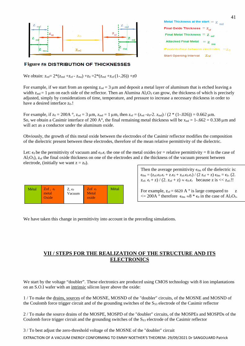
EXTRACTION OF A VACUUM ENERGY CONFORMING TO EMMY NOETHER'S THEOREM: 29/09/2021 Dr SANGOUARD Patrick
41
We obtain: zod= 2*(zmd +zof - zma) +z0 =2*(zmd +zof (1-.26)) +z0
For example, if we start from an opening zod = 3 m and deposit a metal layer of aluminum that is etched leaving a
width zmd = 1 m on each side of the reflector. Then an Alumina Al2O3 can grow, the thickness of which is precisely
adjusted, simply by considerations of time, temperature, and pressure to increase a necessary thickness in order to
have a desired interface z0.!
For example, if z0 = 200A °, zod = 3 m, zmd = 1 m, then zof = (zod -z0-2. zmd) / (2 * (1-.026)) = 0.662 m.
So, we obtain a Casimir interface of 200 A°, the final remaining metal thickness will be xmf = 1-.662 = 0.338 m and
will act as a conductor under the aluminum oxide.
Obviously, the growth of this metal oxide between the electrodes of the Casimir reflector modifies the composition
of the dielectric present between these electrodes, therefore of the mean relative permittivity of the dielectric.
Let: 0 be the permittivity of vacuum and 0.r the one of the metal oxides (r = relative permittivity = 8 in the case of
Al2O3), zof the final oxide thickness on one of the electrodes and z the thickness of the vacuum present between
electrode, (initially we want z = z0).
We have taken this change in permittivity into account in the preceding simulations.
VII / STEPS FOR THE REALIZATION OF THE STRUCTURE AND ITS
ELECTRONICS
We start by the voltage “doubler”. These electronics are produced using CMOS technology with 8 ion implantations
on an S.O.I wafer with an intrinsic silicon layer above the oxide:
1 / To make the drains, sources of the MOSNE, MOSND of the "doubler" circuits, of the MOSNE and MOSND of
the Coulomb force trigger circuit and of the grounding switches of the SS3 electrode of the Casimir reflector
2 / To make the source drains of the MOSPE, MOSPD of the "doubler" circuits, of the MOSPEs and MOSPDs of the
Coulomb force trigger circuit and the grounding switches of the SS3 electrode of the Casimir reflector
3 / To best adjust the zero-threshold voltage of the MOSNE of the "doubler" circuit
Zof , r
metal
Oxide
Z, 0
Vacuum
Zof r
Metal
oxide
Métal Métal
Then the average permittivity 0m of the dielectric is:
0m = (zof.0.r + z.0 + zof.0.r) / (2 zof + z) 0m = 0. (2.
zof. r + z) / (2. zof + z) 0.r because z is << zof.!!
For example, zof = 6620 A ° is large compared to z
<= 200A ° therefore 0m 8 * 0 in the case of Al2O3.
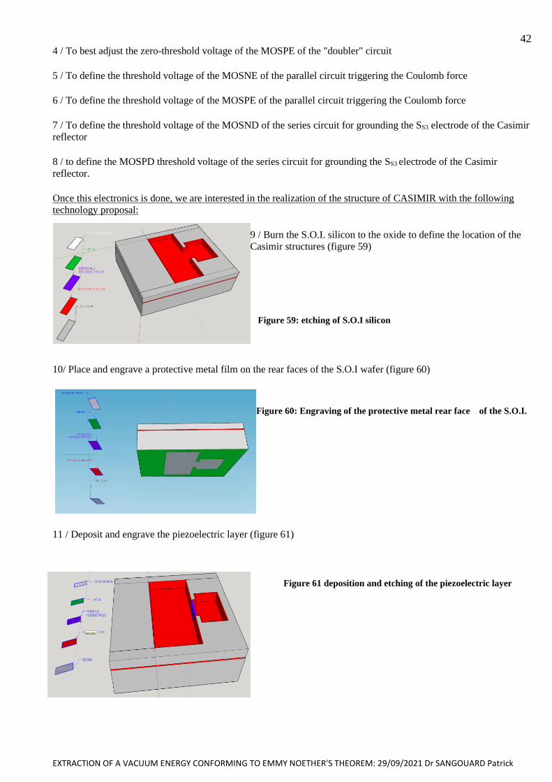
EXTRACTION OF A VACUUM ENERGY CONFORMING TO EMMY NOETHER'S THEOREM: 29/09/2021 Dr SANGOUARD Patrick
42 4 / To best adjust the zero-threshold voltage of the MOSPE of the "doubler" circuit
5 / To define the threshold voltage of the MOSNE of the parallel circuit triggering the Coulomb force
6 / To define the threshold voltage of the MOSPE of the parallel circuit triggering the Coulomb force
7 / To define the threshold voltage of the MOSND of the series circuit for grounding the SS3 electrode of the Casimir
reflector
8 / to define the MOSPD threshold voltage of the series circuit for grounding the SS3 electrode of the Casimir
reflector.
Once this electronics is done, we are interested in the realization of the structure of CASIMIR with the following
technology proposal:
9 / Burn the S.O.I. silicon to the oxide to define the location of the
Casimir structures (figure 59)
Figure 59: etching of S.O.I silicon
10/ Place and engrave a protective metal film on the rear faces of the S.O.I wafer (figure 60)
Figure 60: Engraving of the protective metal rear face of the S.O.I.
11 / Deposit and engrave the piezoelectric layer (figure 61)
Figure 61 deposition and etching of the piezoelectric layer
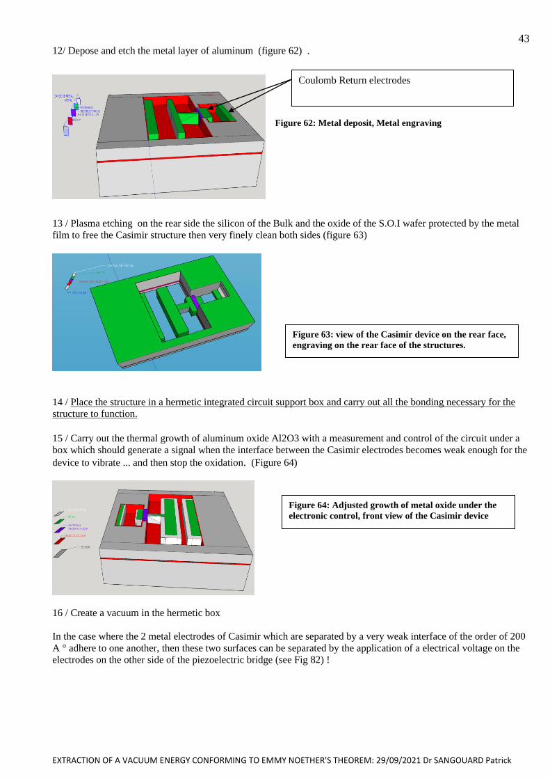
EXTRACTION OF A VACUUM ENERGY CONFORMING TO EMMY NOETHER'S THEOREM: 29/09/2021 Dr SANGOUARD Patrick
43 12/ Depose and etch the metal layer of aluminum (figure 62) .
Figure 62: Metal deposit, Metal engraving
13 / Plasma etching on the rear side the silicon of the Bulk and the oxide of the S.O.I wafer protected by the metal
film to free the Casimir structure then very finely clean both sides (figure 63)
14 / Place the structure in a hermetic integrated circuit support box and carry out all the bonding necessary for the
structure to function.
15 / Carry out the thermal growth of aluminum oxide Al2O3 with a measurement and control of the circuit under a
box which should generate a signal when the interface between the Casimir electrodes becomes weak enough for the
device to vibrate ... and then stop the oxidation. (Figure 64)
16 / Create a vacuum in the hermetic box
In the case where the 2 metal electrodes of Casimir which are separated by a very weak interface of the order of 200
A ° adhere to one another, then these two surfaces can be separated by the application of a electrical voltage on the
electrodes on the other side of the piezoelectric bridge (see Fig 82) !
Figure 63: view of the Casimir device on the rear face,
engraving on the rear face of the structures.
Figure 64: Adjusted growth of metal oxide under the
electronic control, front view of the Casimir device
Coulomb Return electrodes
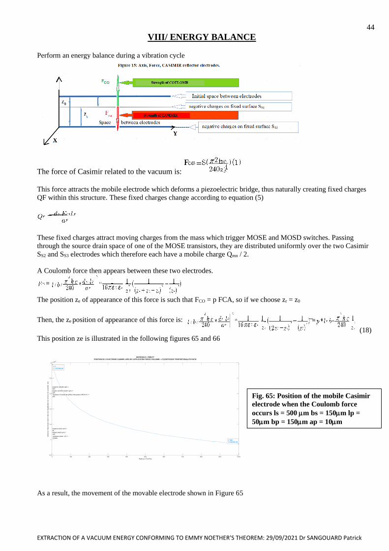
EXTRACTION OF A VACUUM ENERGY CONFORMING TO EMMY NOETHER'S THEOREM: 29/09/2021 Dr SANGOUARD Patrick
44
VIII/ ENERGY BALANCE
Perform an energy balance during a vibration cycle
The force of Casimir related to the vacuum is:
This force attracts the mobile electrode which deforms a piezoelectric bridge, thus naturally creating fixed charges
QF within this structure. These fixed charges change according to equation (5)
These fixed charges attract moving charges from the mass which trigger MOSE and MOSD switches. Passing
through the source drain space of one of the MOSE transistors, they are distributed uniformly over the two Casimir
SS2 and SS3 electrodes which therefore each have a mobile charge Qmn / 2.
A Coulomb force then appears between these two electrodes.
The position ze of appearance of this force is such that FCO = p FCA, so if we choose zr = z0
Then, the ze position of appearance of this force is:
(18)
This position ze is illustrated in the following figures 65 and 66
As a result, the movement of the movable electrode shown in Figure 65
Fig. 65: Position of the mobile Casimir
electrode when the Coulomb force
occurs ls = 500 m bs = 150m lp =
50m bp = 150m ap = 10m
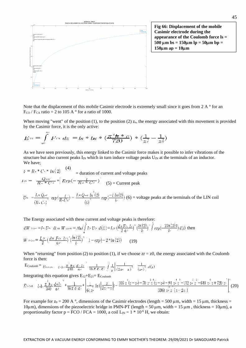
EXTRACTION OF A VACUUM ENERGY CONFORMING TO EMMY NOETHER'S THEOREM: 29/09/2021 Dr SANGOUARD Patrick
45
Note that the displacement of this mobile Casimir electrode is extremely small since it goes from 2 A ° for an
FCO / FCA ratio = 2 to 105 A ° for a ratio of 1000.
When moving "went" of the position (1), to the position (2) ze, the energy associated with this movement is provided
by the Casimir force, it is the only active:
As we have seen previously, this energy linked to the Casimir force makes it possible to infer vibrations of the
structure but also current peaks IIN which in turn induce voltage peaks UIN at the terminals of an inductor.
We have;
(4)
= duration of current and voltage peaks
(5) = Current peak
(6) = voltage peaks at the terminals of the LIN coil
The Energy associated with these current and voltage peaks is therefore:
& then
(19)
When "returning" from position (2) to position (1), if we choose zr = z0, the energy associated with the Coulomb
force is then:
ECoulomb =
Integrating this equation gives E12+E21= ECoulomb
(20)
For example for z0 = 200 A °, dimensions of the Casimir electrodes (length = 500 m, width = 15 m, thickness =
10m), dimensions of the piezoelectric bridge in PMN-PT (length = 50 m, width = 15 m , thickness = 10m), a
proportionality factor p = FCO / FCA = 1000, a coil LIN = 1 * 10-6 H, we obtain:
Fig 66: Displacement of the mobile
Casimir electrode during the
appearance of the Coulomb force ls =
500 m bs = 150m lp = 50m bp =
150m ap = 10m
EXTRACTION OF A VACUUM ENERGY CONFORMING TO EMMY NOETHER'S THEOREM: 29/09/2021 Dr SANGOUARD Patrick
46 • Ze = 9.46 10-09 (m) i.e., a displacement of the mobile Casimir electrode of about 105A ° (fig 64)
• E12 = ECasimir = 3.4 10-11 (Joule) = Energy of Casimir expended by the vacuum.
• E12 + E21 = ECoulomb = 1.49e-8 (Joule) = Energy of the Coulomb force.
• Peak current = 350 10-6 A
• Voltage peak across the coil = 1.2 V
• Structure vibration frequency = 750 kHz
• Welectric = 2.7 10-11 (Joule) = Usable energy associated with current and voltage peaks.
This energy is not brought by an external electrical source but is caused by the omnipresent and perpetual force of
Casimir, itself controlled by a Coulomb force of opposite direction.
This Coulomb force appears by the automatic switching of MOS transistors when its intensity is greater than a
predetermined value and opposite to that of the Casimir force.
This technologically programmable switching of the MOS switches induces the spontaneous appearance of current
peaks of a few nanoseconds, themselves inducing voltage peaks at the terminals of an inductor. When the system
returns to its starting position, the Coulomb force disappears, leaving the Casimir force to deform the structure again!
The system then spontaneously enters into vibrations!
We observe that the usable energy = Welectric is less than ECasimir. The energy balance of a cycle therefore seems to
satisfy Emmy NOTHER's theorem!
IX / CONCLUSIONS
1 / the proposal to use isotropic and perpetual energy of Casimir called Energy of the vacuum, to obtain a variation
of electric charges of a piezoelectric bridge which generates current peaks at the frequency of self-sustaining
vibrations of the structure, usable without no energy input
2 / the system which should allow the conversion of this vacuum energy into alternating current peaks at the
vibration frequency of the system. This current passes through an inductor which converts these alternating current
peaks into alternating voltage peaks.
3 / The current and the voltage at the terminals of this choke feed electronics which rectifies and amplifies, without
any external power supply, these voltage peaks in a direct voltage of a few usable volts.
4 / a proposal for micro and nano electronic technology giving hope for a possible realization of this set.
According to this study, it would seem that unless we are mistaken we can extract energy from the vacuum by the
use of the Casimir force thwarted at the appropriate time by a temporary Coulomb force which makes the system
return to its initial position and makes enter into vibrations the structure!!
I am fully aware that this concept may sound like a crazy idea, but it does not seem to contradict Emmy Noether's
theorem and, mathematical calculations and simulations give encouraging results and merit further study of this
concept by a thesis.
I am looking for a microelectronics laboratory with sufficient technological and design resources for a doctoral
student to confirm or deny this idea of a retired dreamer.
The dreamer would be, with pleasure, the thesis supervisor of this concept.Dr Patrick SANGOUARD
7 Allée Guillaume Apollinaire 21000 Dijon
Tel :06 86 50 78 44
Email : [email protected]
EXTRACTION OF A VACUUM ENERGY CONFORMING TO EMMY NOETHER'S THEOREM: 29/09/2021 Dr SANGOUARD Patrick
47
BIBLIOGRAPHIE
[1]Fluctuations du vide quantique : Serge Reynaud Astrid Lambrecht( a) , Marc Thierry Jaekel ( b)
a / Laboratoire Kastler Brossel UPMC case Jussieu F Paris Cedex 05
b / Laboratoire de Physique Théorique de l’ENS 24 rue Lhomond F 75231 Paris Cedex 05 , Juin 2001
[2] H.B.G. Casimir, Proc. Kon. Nederl. Akad. Wet. 51 793 (1948)
[3] B.V. Deriagin and I.I. Abrikosova, Soviet Physics JETP 3 819 (1957)
[4] E.M. Lifshitz, Sov. Phys. JETP 2 73 (1956); E.M. Lifshitz and L.P. Pitaevskii, Landau and Lifshitz Course of
Theoretical Physics: Statistical Physics Part 2 ch VIII (Butterworth-Heinemann, 1980)
[5] Techniques de l’Ingénieur : l’expertise technique et scientifique de référence
« Applications des éléments piézoélectriques en électronique de puissance » Dejan VASIC: Maître de conférences à
l’université de Cergy-Pontoise, Chercheur au laboratoire SATIE ENS Cachan, François COSTA: Professeur à
l’université de Paris Est Créteil, Chercheur au laboratoire SATIE ENS Cachan
[6] 1. Wachel, J. C., and Bates, C. L., “Techniques for controlling piping vibration failures”, ASME Paper, 76-Pet-
18, 1976.
[7] Jayalakshmi Parasuraman, Anand Summanwar ,Frédéric Marty , Philippe Basset , Dan E. Angelescu , Tarik
Bourouina « Deep reactive ion etching of sub-micrometer trenches with ultra-high aspect ratio Microelectronic
Engineering » Volume 113, January 2014, Pages 35-39
[8] F. Marty, L. Rousseau, B. Saadanya, B. Mercier, O. Français, Y. Mitab, T. Bourouina,«Advanced etching of
silicon based on deep reactive ion etching for silicon high aspect ratio microstructures and three-dimensional micro-
and nanostructure» Microelectronics Journal 36 (2005) 673–677
[9] Semiconductor Devices S. M. Sze Physics and Technology
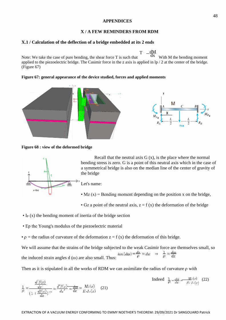
EXTRACTION OF A VACUUM ENERGY CONFORMING TO EMMY NOETHER'S THEOREM: 29/09/2021 Dr SANGOUARD Patrick
48
APPENDICES
X / A FEW REMINDERS FROM RDM
X.1 / Calculation of the deflection of a bridge embedded at its 2 ends
Note: We take the case of pure bending, the shear force T is such that T
dxdM
With M the bending moment
applied to the piezoelectric bridge. The Casimir force in the z axis is applied in lp / 2 at the center of the bridge.
(Figure 67)
Figure 67: general appearance of the device studied, forces and applied moments
Figure 68 : view of the deformed bridge
Recall that the neutral axis G (x), is the place where the normal
bending stress is zero. G is a point of this neutral axis which in the case of
a symmetrical bridge is also on the median line of the center of gravity of
the bridge
Let's name:
• Mz (x) = Bending moment depending on the position x on the bridge,
• Gz a point of the neutral axis, z = f (x) the deformation of the bridge
• IP (x) the bending moment of inertia of the bridge section
• Ep the Young's modulus of the piezoelectric material
• = the radius of curvature of the deformation z = f (x) the deformation of this bridge.
We will assume that the strains of the bridge subjected to the weak Casimir force are themselves small, so
the induced strain angles d () are also small. Thus: . & .
Then as it is stipulated in all the works of RDM we can assimilate the radius of curvature with
Indeed (22)
(21)
. .
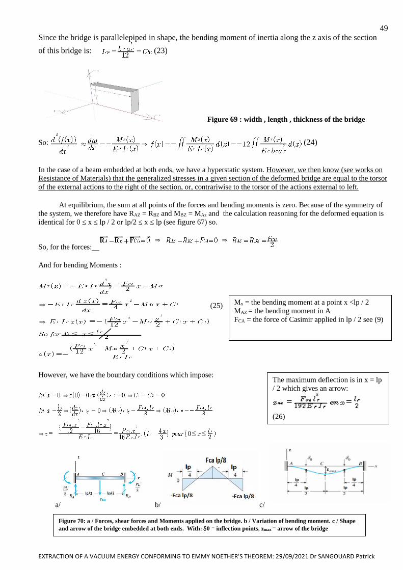
EXTRACTION OF A VACUUM ENERGY CONFORMING TO EMMY NOETHER'S THEOREM: 29/09/2021 Dr SANGOUARD Patrick
49
Since the bridge is parallelepiped in shape, the bending moment of inertia along the z axis of the section
of this bridge is: (23)
Figure 69 : width , length , thickness of the bridge
So: . & (24)
In the case of a beam embedded at both ends, we have a hyperstatic system. However, we then know (see works on
Resistance of Materials) that the generalized stresses in a given section of the deformed bridge are equal to the torsor
of the external actions to the right of the section, or, contrariwise to the torsor of the actions external to left.
At equilibrium, the sum at all points of the forces and bending moments is zero. Because of the symmetry of
the system, we therefore have RAZ = RBZ and MBZ = MAz and the calculation reasoning for the deformed equation is
identical for 0 ≤ x ≤ lp / 2 or lp/2 ≤ x ≤ lp (see figure 67) so.
So, for the forces: & &
And for bending Moments :
&
&
# #
(25)
However, we have the boundary conditions which impose:
& &
& & &
& # #
a/ b/ c/
Mx = the bending moment at a point x <lp / 2
MAZ = the bending moment in A
FCA = the force of Casimir applied in lp / 2 see (9)
Figure 70: a / Forces, shear forces and Moments applied on the bridge. b / Variation of bending moment. c / Shape
and arrow of the bridge embedded at both ends. With: 0 = inflection points, zmax = arrow of the bridge
The maximum deflection is in x = lp
/ 2 which gives an arrow:
(26)

EXTRACTION OF A VACUUM ENERGY CONFORMING TO EMMY NOETHER'S THEOREM: 29/09/2021 Dr SANGOUARD Patrick
50 X.2 / Calculation of the resonant frequency of the piezoelectric bridge
We have seen that the differential equation of the deformation of the bridge reduces to:
The minus sign comes from the fact that the deformation z(x) is in the reference frame x, y, z while the moment of
bending M(x) is defined in the Frenet trihedron: tangent t, normal n and bi normal r. (figure 71)
Let us calculate the differential equation of the deformation in terms of linear loading q (x)= dV/dx (N/m). In the
Frenet trihedron, we write then the mechanical equilibrium of the beam section of length dx subjected to the linear
loading q (x).
The balance of forces (nullity of the resultant) is written: -V +q dx +V + dV =0. So, q(x)= - dV / dx.
The balance of moments with respect to the origin of the trihedron is written:
In projection on the z axis: -M+ (V +dV) dx +M +dM=0. Hence, neglecting the second order term dV dx: we obtain
V(x)= -dM / dx q(x)= dV/ dx = - d2 M/ dx2
By differentiating twice, the differential equation of the deformation written in terms of bending
moment Mz and considering the two preceding relations, this equation is finally written in terms of linear loading:
(27)
X.2.1 / Differential equation of a vibrating beam and determination of the eigen modes
We consider a rectangular beam (figure 67, 69) of thickness ap, width bp and length lp. Let S (m2) be the section,
the density (Kg/m3), Ep the Young modulus with the inertia of the cross section of the beam in the width direction bp.
It is demonstrated (see for example: Vibrations of continuous media Jean-Louis Guyader
(Hermes)) that the amplitude z (x, t) of the transverse displacement of a cross section of the beam is given by the
partial differential equation: , if one neglects the internal damping!
The linear mass m(x) being equal to S (Kg/m), the linear inertia force F(x) induced by the vibration will be
F(x) = - m (x) (x) = - S d2z (x) / dt2 with (x) = d2z (x) / dt2 = acceleration induced by vibration, hence the
differential equation of free vibrations deduced is:
(28) Considering the weak bending assumptions, the solution of this equation will be
acceptable only insofar the amplitude of the vibrations az remains small compared to the thickness ap: az << ap.
By setting: z (x, t) = Z (x) exp (i..t) with (i = pure imaginary), and by separating the temporal Z(x) and spatial parts
exp (I..t), the equation differential (28) expressing the amplitude Z(x) of the deformation at the pulsation gives:
With
Figure 71; Section, Frenet trihedron
&
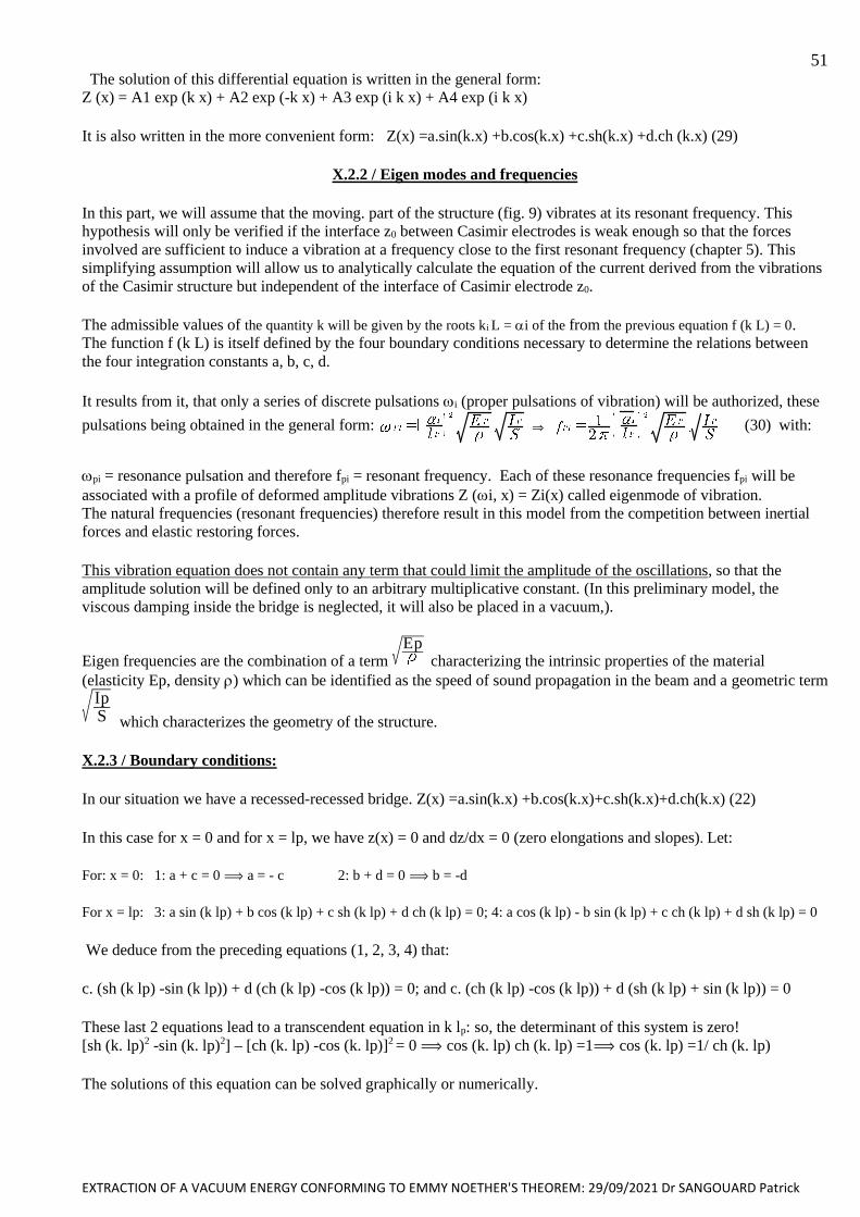
EXTRACTION OF A VACUUM ENERGY CONFORMING TO EMMY NOETHER'S THEOREM: 29/09/2021 Dr SANGOUARD Patrick
51 The solution of this differential equation is written in the general form:
Z (x) = A1 exp (k x) + A2 exp (-k x) + A3 exp (i k x) + A4 exp (i k x)
It is also written in the more convenient form: Z(x) =a.sin(k.x) +b.cos(k.x) +c.sh(k.x) +d.ch (k.x) (29)
X.2.2 / Eigen modes and frequencies
In this part, we will assume that the moving. part of the structure (fig. 9) vibrates at its resonant frequency. This
hypothesis will only be verified if the interface z0 between Casimir electrodes is weak enough so that the forces
involved are sufficient to induce a vibration at a frequency close to the first resonant frequency (chapter 5). This
simplifying assumption will allow us to analytically calculate the equation of the current derived from the vibrations
of the Casimir structure but independent of the interface of Casimir electrode z0.
The admissible values of the quantity k will be given by the roots ki L = i of the from the previous equation f (k L) = 0.
The function f (k L) is itself defined by the four boundary conditions necessary to determine the relations between
the four integration constants a, b, c, d.
It results from it, that only a series of discrete pulsations i (proper pulsations of vibration) will be authorized, these
pulsations being obtained in the general form: & (30) with:
pi = resonance pulsation and therefore fpi = resonant frequency. Each of these resonance frequencies fpi will be
associated with a profile of deformed amplitude vibrations Z (i, x) = Zi(x) called eigenmode of vibration.
The natural frequencies (resonant frequencies) therefore result in this model from the competition between inertial
forces and elastic restoring forces.
This vibration equation does not contain any term that could limit the amplitude of the oscillations, so that the
amplitude solution will be defined only to an arbitrary multiplicative constant. (In this preliminary model, the
viscous damping inside the bridge is neglected, it will also be placed in a vacuum,).
Eigen frequencies are the combination of a term Ep
characterizing the intrinsic properties of the material
(elasticity Ep, density ) which can be identified as the speed of sound propagation in the beam and a geometric term
SIp
which characterizes the geometry of the structure.
X.2.3 / Boundary conditions:
In our situation we have a recessed-recessed bridge. Z(x) =a.sin(k.x) +b.cos(k.x)+c.sh(k.x)+d.ch(k.x) (22)
In this case for x = 0 and for x = lp, we have z(x) = 0 and dz/dx = 0 (zero elongations and slopes). Let:
For: x = 0: 1: a + c = 0 a = - c 2: b + d = 0 b = -d
For x = lp: 3: a sin (k lp) + b cos (k lp) + c sh (k lp) + d ch (k lp) = 0; 4: a cos (k lp) - b sin (k lp) + c ch (k lp) + d sh (k lp) = 0
We deduce from the preceding equations (1, 2, 3, 4) that:
c. (sh (k lp) -sin (k lp)) + d (ch (k lp) -cos (k lp)) = 0; and c. (ch (k lp) -cos (k lp)) + d (sh (k lp) + sin (k lp)) = 0
These last 2 equations lead to a transcendent equation in k lp: so, the determinant of this system is zero!
[sh (k. lp)2 -sin (k. lp)2] – [ch (k. lp) -cos (k. lp)]2 = 0 cos (k. lp) ch (k. lp) =1 cos (k. lp) =1/ ch (k. lp)
The solutions of this equation can be solved graphically or numerically.
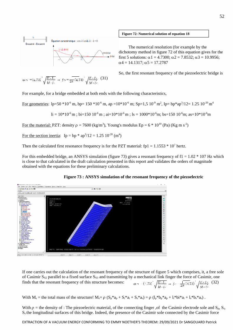
EXTRACTION OF A VACUUM ENERGY CONFORMING TO EMMY NOETHER'S THEOREM: 29/09/2021 Dr SANGOUARD Patrick
52
The numerical resolution (for example by the
dichotomy method in figure 72 of this equation gives for the
first 5 solutions: 1 = 4.7300; 2 = 7.8532; 3 = 10.9956;
4 = 14.1317; 5 = 17.2787
So, the first resonant frequency of the piezoelectric bridge is
& (31)
For example, for a bridge embedded at both ends with the following characteristics,
For geometries: lp=50 *10-6 m, bp= 150 *10-6 m, ap =10*10-6 m; Sp=1,5 10-9 m2, Ip= bp*ap3/12= 1.25 10-20 m4
li = 10*10-6 m ; bi=150 10-6 m ; ai=10*10-6 m ; ls = 1000*10-6m; bs=150 10-6m; as=10*10-6m
For the material: PZT: density = 7600 (kg/m3), Young's modulus Ep = 6 * 1010 (Pa) (Kg m s-2)
For the section inertia: Ip = bp * ap3/12 = 1.25 10-20 (m4)
Then the calculated first resonance frequency is for the PZT material: fp1 = 1.1553 * 107 hertz.
For this embedded bridge, an ANSYS simulation (figure 73) gives a resonant frequency of f1 = 1.02 * 107 Hz which
is close to that calculated in the draft calculation presented in this report and validates the orders of magnitude
obtained with the equations for these preliminary calculations.
Figure 73 : ANSYS simulation of the resonant frequency of the piezoelectric
If one carries out the calculation of the resonant frequency of the structure of figure 5 which comprises, it, a free sole
of Casimir SS2 parallel to a fixed surface SS3 and transmitting by a mechanical link finger the force of Casimir, one
finds that the resonant frequency of this structure becomes: & (32)
With Ms = the total mass of the structure! Ms= (Sp*ap + Si*ai + Ss*as) = (lp*bp*ap + li*bi*ai + ls*bs*as) .
With = the density of : The piezoelectric material, of the connecting finger ,of the Casimir electrode sole and Sp, Si,
Ss the longitudinal surfaces of this bridge. Indeed, the presence of the Casimir sole connected by the Casimir force
Figure 72: Numerical solution of equation 18
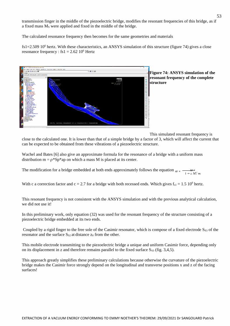
EXTRACTION OF A VACUUM ENERGY CONFORMING TO EMMY NOETHER'S THEOREM: 29/09/2021 Dr SANGOUARD Patrick
53 transmission finger in the middle of the piezoelectric bridge, modifies the resonant frequencies of this bridge, as if
a fixed mass MS were applied and fixed in the middle of the bridge.
The calculated resonance frequency then becomes for the same geometries and materials
fs1=2.509 106 hertz. With these characteristics, an ANSYS simulation of this structure (figure 74) gives a close
resonance frequency : fs1 = 2.62 106 Hertz
Figure 74: ANSYS simulation of the
resonant frequency of the complete
structure
This simulated resonant frequency is
close to the calculated one. It is lower than that of a simple bridge by a factor of 3, which will affect the current that
can be expected to be obtained from these vibrations of a piezoelectric structure.
Wachel and Bates [6] also give an approximate formula for the resonance of a bridge with a uniform mass
distribution m = *Sp*ap on which a mass M is placed at its center.
The modification for a bridge embedded at both ends approximately follows the equation
With c a correction factor and c = 2.7 for a bridge with both recessed ends. Which gives fs1 = 1.5 106 hertz.
This resonant frequency is not consistent with the ANSYS simulation and with the previous analytical calculation,
we did not use it!
In this preliminary work, only equation (32) was used for the resonant frequency of the structure consisting of a
piezoelectric bridge embedded at its two ends.
Coupled by a rigid finger to the free sole of the Casimir resonator, which is compose of a fixed electrode SS3 of the
resonator and the surface SS2 at distance z0 from the other.
This mobile electrode transmitting to the piezoelectric bridge a unique and uniform Casimir force, depending only
on its displacement in z and therefore remains parallel to the fixed surface SS3 (fig. 3,4,5).
This approach greatly simplifies these preliminary calculations because otherwise the curvature of the piezoelectric
bridge makes the Casimir force strongly depend on the longitudinal and transverse positions x and z of the facing
surfaces!