dewatering and filtration unit fluidaqua mobil fam 10 - hydac · and filtration unit fluidaqua...
TRANSCRIPT

EN 7
.949
.7/0
6.18
215
Dewatering and Filtration Unit FluidAqua MobilFAM 10
DescriptionThe FluidAqua Mobil FAM 10 series operates according to the principle of vacuum dewatering to separate free and dissolved water as well as free and dissolved gases from hydraulic and lubrication fluids.
By using HYDAC bypass filter technology, with its high contamination retention capacity and separation performance, the unit achieves a very high level of cost effectiveness. All units have an AquaSensor AS 1000 to continuously monitor the water content and to control the unit. A CS 1000 particle sensor for simultaneous monitoring of the solid particle contamination can be integrated optionally.
To increase the dewatering capacity, a heater can be integrated optionally for highly viscous fluids or for low fluid temperatures.
The Siemens S7 series programmable logic controller (PLC) used in combination with a Siemens touch control panel guarantees simple and reliable handling in numerous local languages.
AdvantagesExtremely low residual water levels, gas levels and particle contamination in the operating fluids make for:
zLonger oil change intervals z Improved component service life zGreater machine availability zReduction in the LifeCycle Cost (LCC)
Technical specificationsFlow rates at 50 Hz ≈ 10 l/min (FAM-10), ≈ 15 l/min (FAM-10/15)Flow rates at 60 Hz ≈ 12 l/min (FAM-10), ≈ 18 l/min (FAM-10/15)Permitted fluids** Fluids compatible with NBR seals:
z Mineral oils to DIN 51524 z Gear oils to DIN 51517, 51524Fluids compatible with FKM (Viton®) seals: z Synthetic esters (HEES) DIN 51524/2 z Vegetable oils (HETG, HTG) z HFD-R fluids (not for pure phosphate ester which requires EPDM seals).Fluids compatible with EPDM seals: z Aviation phosphoric acid esters e. g. Skydrol® or Hyjet®
Viscosity range 15 to 800 mm²/sSealing material see model codeFilter size of fine filter OLF-5Filter elements of fine filter xxx= Filtration rating N5DMxxx (please order separately.)Contamination retention capacity to ISO 4572 200 gClogging indicator VM 2 C.0Setting pressure of differential pressure clogging indicator 2 bar
Pump type, filtration unit Vane pumpPump type, drainage pump Gear pumpPump type, vacuum pump Rotary vane vacuum pumpOperating pressure max. 6 barPermitted pressure at suction port (without suction hose) **
-0.2 to +1 bar
Permitted pressure at outlet (without return hose) **
0 to 3.5 bar
Fluid temperature range** 10 to 80°CAmbient temperature ** 10 to 40°CStorage temperature range 10 to 50 °CElectrical power consumption FAM 10 / 10/15 * (50 Hz) *
standard: ≈ 1800/2000 W with heater: ≈ 4700/4900 W
External fuse required 16 A or 32 A (see Model code) for circuit breakers with trip characteristics type C
Heating output (optional) ≈ 2900 W only for 3 phase version
Protection class IP 54Power cable, length 10 mHoses, length 5 mMaterial of hoses see model codeInlet / outlet connection see "FAM Connection summary"Weight when empty ≈ 300 kgAchievable residual water content
< 100 ppm – hydraulic and lubrication oils < 50 ppm – turbine oils (ISO VG 32/46) < 10 ppm – transformer oils ***
* Maximum specifications given, equipment-dependent ** For other fluids, viscosities or temperature ranges, please contact us. *** Units not suitable for "Online" and "Onload" operation (transformer in operation and connected to grid).

EN 7
.949
.7/0
6.18
216
Model code FAM – 10 – M – 1 – A – 05 – R – H – C1 – AC1 – 00 – /-VBasic model FAM = FluidAqua Mobil
Size and nominal flow rate 10 ≈ 10 l/min (for 50 Hz operation), ≈ 12 l/min (of 60 Hz operation) 10/15 ≈ 15 l/min (for 50 Hz operation), ≈ 18 l/min (for 60 Hz operation)
Operating fluid M = Mineral oil - NBR seals, NBR hoses, tested using mineral oil * I = Insulating oil - NBR seals, NBR hoses, tested using insulating oil ** X = HFD-R phosphoric acid ester fluids - FKM seals, UPE hoses tested using HFD-R fluid * P = Aviation phosphoric acid ester fluid e.g. Skydrol® or Hyjet IV-A*, EPDM seals tested using Hyjet® B = Biodegradable oils (based on esters) - FKM seals, NBR hoses, tested using rapidly biodegradable fluid (based on esters) *
Mechanical type 1 = Stationary (with feet) 2 = Mobile (with castors and hose attachment)
Voltage / frequency / power supply A = 400 V/50 Hz/3Ph+PE B = 415 V/50 Hz/3Ph+PE C = 200 V/50 Hz/3Ph+PE 1) *** D = 200 V/60 Hz/3Ph+PE 1) *** E = 220 V/60 Hz/3Ph+PE F = 230 V/60 Hz/3Ph+PE *** G = 380 V/60 Hz/3Ph+PE H = 440 V/60 Hz/3Ph+PE 1) J = 230 V/50 Hz/3Ph+PE *** K = 480 V/60 Hz/3Ph+PE 1) L = 220 V/50 Hz/3Ph+PE *** M = 230 V/50 Hz/1Ph+PE (heater not possible) N = 575 V/60 Hz/3Ph+PE 1) O = 460 V/60 Hz/3Ph+PE 1) X = other voltage on request
Filter size of fine filter 05 = OLF-5
Type of vacuum pump R = Rotary vane vacuum pump
Heater H = heater (only for 3-phase version) Z = without heater
Control concept C1 = Comfort, control panel language de/en/fr/es/pt/it/nl/da/fi/sv C2 = Comfort, control panel language de/en/bg/hu/ru/pl/zh (other languages on request)
Monitoring sensors A = AquaSensor AC1 = AquaSensor + ContaminationSensor ISO4406:1999 AC2 = AquaSensor + ContaminationSensor SAE AS 4059(D) AC3 = AquaSensor + ContaminationSensor NAS 1638
Modification number 00 = the latest version is always supplied
Supplementary details No details = standard V = FKM seals for operating fluid "M" and "I" (if non-standard seal required for the particular operating fluid) (see Model Code under "Operating fluid") : Example:. FAM-10-M....-/V)
1) Supplied without plug * Residues of test fluid will remain in the unit after testing. ** Units not suitable for "Online" and "Onload" operation (transformer in operation and connected to grid). *** For heater option, 32A plug and fuse required.

EN 7
.949
.7/0
6.18
217
Heater optionBy using the built-in heater, the dewatering capacity can be increased particularly in the case of high viscosity fluids or fluids at low temperatures. If the temperature of the fluid is raised by 10 °C then the dewatering capacity increases by up to 50%. The ideal temperature for dewatering is roughly 50 to 60 °C. Generally speaking, for operating viscosities of between 350 and 800 mm²/s the heater option must be selected and the heater must be used.
Type of vacuum pumpThe vacuum pump used is an oil-lubricated rotary vane vacuum pump. Along with the removed water, the air that emerges from the vacuum pump can contain components of the operating fluid to be cleaned, which may include gases. Therefore, please ensure that the area in which the FAM is operated is adequately ventilated.
Hydraulic circuit diagram
1 Suction filter 15 Pressure sensor for measuring the pre-set vacuum
2 AquaSensor AS 1000 16 Vacuum pump3 Filling pump 19 Level sensor for vacuum column
4 Check valve 20 Pump for ContaminationSensor CS1000 (optional)
5 Vacuum column 21 ContaminationSensor CS1000 (optional)6 Heater (optional) 22 Pressure relief valve for CS1000 (optional)7 Drain pump 23 Pressure relief valve for CS1000 (optional)8 Check valve 24 Leakage indicator for oil drip tray9 Fluid filter for eliminating solid particles 25 Drain for vacuum column10 Differential pressure switch for
monitoring the filter26 Return valve
11 Drain for fluid filter 27 Temperature sensor (for the heater (6) option)13 Air filter and dryer 28 Drain for vacuum pump14 Needle valve for vacuum setting 29 Level sensor for vacuum pump
30 Ball valve
InstrumentationThe integrated AquaSensor (AS) enables continuous display of the water content relative to the saturation concentration (saturation level) along with the temperature of the fluid. The optional ContaminationSensor (CS) determines the solid particle contamination of the fluid and displays it in the control panel. The units can also be controlled via both sensors fully automatically for state-based and thus energy-saving operation.
External interfacesThe controller has external interfaces for remote control of the unit:
zStart/stop from external (relay) zDevice ready – no error, unit ready for operation (potential-free contact) zOperating state – unit ON/OFF (potential-free contact)
Control concept zSiemens S7-1200 with 4" KTP400 TFT colour display with touch and key operation
zDisplay of water content (% saturation), fluid temperature and optional particle contamination in numerical and graphic form with graphical progress display of measured values
zAutomatic, state-based and energy-saving operation through control of the unit via integrated or external AquaSensor or integrated ContaminationSensor zDisplay of hydraulic circuit diagram for active or defective components, such as motors/pumps, level sensors and heaters
zError messages as plain text display and menu-guided troubleshooting zUp to 10 selectable languages integrated zExpandable for Ethernet connection and web server for remote monitoring (see accessories)

EN 7
.949
.7/0
6.18
218
SizingAs a rough guide, the FluidAqua Mobil can be sized according to the tank volume of the system. If the water ingress per hour is known, then a unit can be selected according to the typical dewatering capacities of the various sizes.
Tank volume in litres
FAM
< 2,000 FAM 5 *
1,000 – 7,000 FAM 10/15 / 10
7,000 – 15,000 FAM 25 **
15,000 – 25,000 FAM 45 ** FAM 45E***
25,000 – 35,000 FAM 60 **
35,000 – 45,000 FAM 75 ** / FAM 75E ***
> 45,000 FAM 95 **
* see Brochure no. 7.639. FAM 5 ** see Brochure no. 7.613. FAM 25/45/60/75/95*** see Brochure no. 7.654. FAM Economy Series
zSelect a larger size for systems with very high and continuous process-related water entry z In contrast, for systems with just a small amount of moisture entry via tank breathing, one size smaller can be selected z Ideally the water content will be measured periodically to determine the water entry per hour/day. Our sales specialists can then determine the suitable size if they know the oil type, oil temperature, operating viscosity, system dimensions, environmental conditions and target water content
In general, it must however be noted that sizing will depend on the application, the fluid, the temperature of the fluid and the ambient temperature, the fluid quantity and the water ingress into the system. These factors have a major influence on the dewatering performance. The information can thus only serve as a general reference.
Dewatering rate
Water content Fluid temperature Detergent additives Flow rate of the FAM
For dimensioning and project planning, please use the FAM checklist, doc. no.: 10000495854
Measurementsmobile
1760
923
800
800800
800
620
1010
980
5101
2
102 110
556
Required working area
stationary
A
1760
923
800
800800
800
620
1007
980
12
102 110
556
112
5108x
Ø18
802 14
View A
Preferred models (with shorter delivery times)Part no.: Model code3726043 FAM-10/15-M-2-A-05-R-H-C1-AC1-2 4292379 FAM-10/15-M-2-A-05-R-H-C2-AC1-2
EN 7
.949
.7/0
6.18
219
Filter elements for fine filterFilter elements for the fine filter must be ordered separately and must be fitted before commissioning on site.
FAM-10OLF 5: 1 filter element of the type N5DMxxx is required. For operating medium "P": N5DMxxx-EPDM required.Part number Designation Filtration rating Seal 349494 (3203901) N5DM002 (-EPDM) 2 µm FKM (EPDM) 3068101 (3832764) N5DM005 (-EPDM) 5 µm FKM (EPDM) 3102924 (4093756) N5DM010 (-EPDM) 10 µm FKM (EPDM) 3023508 (4093759) N5DM020 (-EPDM) 20 µm FKM (EPDM)
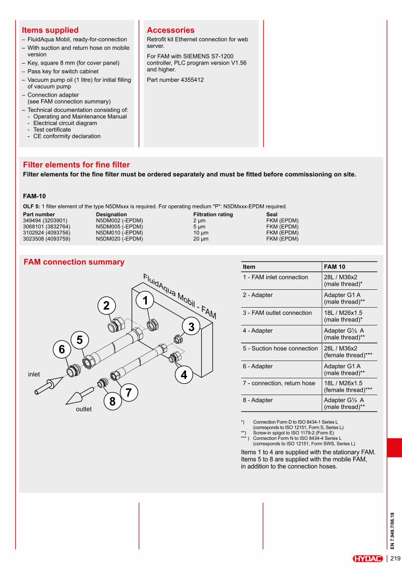
FAM connection summary
1
3
2
56
47
8
inlet
outlet
*) Connection Form D to ISO 8434-1 Series L (corresponds to ISO 12151, Form S, Series L) **) Screw-in spigot to ISO 1179-2 (Form E) *** ) Connection Form N to ISO 8434-4 Series L (corresponds to ISO 12151, Form SWS, Series L)
Items 1 to 4 are supplied with the stationary FAM. Items 5 to 8 are supplied with the mobile FAM, in addition to the connection hoses.
Item FAM 101 - FAM inlet connection 28L / M36x2
(male thread)*
2 - Adapter Adapter G1 A (male thread)**
3 - FAM outlet connection 18L / M26x1.5 (male thread)*
4 - Adapter Adapter G½ A (male thread)**
5 - Suction hose connection 28L / M36x2 (female thread)***
6 - Adapter Adapter G1 A (male thread)**
7 - connection, return hose 18L / M26x1.5 (female thread)***
8 - Adapter Adapter G½ A (male thread)**
Items supplied – FluidAqua Mobil, ready-for-connection – With suction and return hose on mobile version
– Key, square 8 mm (for cover panel) – Pass key for switch cabinet – Vacuum pump oil (1 litre) for initial filling of vacuum pump
– Connection adapter (see FAM connection summary)
– Technical documentation consisting of: - Operating and Maintenance Manual - Electrical circuit diagram - Test certificate - CE conformity declaration
AccessoriesRetrofit kit Ethernet connection for web server.
For FAM with SIEMENS S7-1200 controller, PLC program version V1.56 and higher.
Part number 4355412

EN 7
.949
.7/0
6.18
220
HYDAC FILTER SYSTEMS GMBHIndustriegebiet D-66280 Sulzbach / Saar, Germany Tel.: +49 (0) 6897/509-01 Fax: +49 (0) 6897/509-9046 Internet: www.hydac.com E-mail: [email protected]
NoteThe information in this brochure relates to the operating conditions and applications described.For applications and operating conditions not described, please contact the relevant technical department.Subject to technical modifications.