differential system design and power delivery *other names and brands may be claimed as the property...
TRANSCRIPT
Differential System Design and Power Delivery
Vishram S. Pandit and Michael Mirmak
Intel Corp.IBIS Summit at DesignCon
February 9, 2006
Acknowledgements:
Julius Delino, Sanjiv Soman, Woong Hwan Ryu, Arpad Muranyi, Henri Maramis
Copyright © 2006, Intel Corporation. All rights reserved.

2 *Other names and brands may be claimed as the property of others
Motivation
• Common assumptions for differential system design…– Currents in differential lines are equal and opposite
Summation of currents in sig and sig# (differential lines) is zero
– Current in power equals current in ground at the driver
• These are not valid for all differential systems
• Understanding current behavior is key to proper differential power delivery design
• IBIS* community needs to address this behavior for system simulations

3 *Other names and brands may be claimed as the property of others
Outline
• Driver and termination types used in differential current analysis– “Differential” driver types
• Fully, Half and Pseudo – Termination schemes and current profiles
• Power, Ground, Between Lines, PI
• Detailed analysis of the popular half differential driver design– Currents in
• Power and ground at driver• Differential lines
• Power Delivery (PD) design examples– Normal operation vs. driver power on/off– IBIS model usage

4 *Other names and brands may be claimed as the property of others
Typical Differential Driver Types (1)
I
R R
Gnd
Power
I
Gnd
I
Power
A
A
B
B
Fully Differential Half Differential Pseudo Differential
Gnd Gnd
Power
(1) IBIS Modeling Cookbook for IBIS Ver. 4
May have separate bias
circuit
5 *Other names and brands may be claimed as the property of others
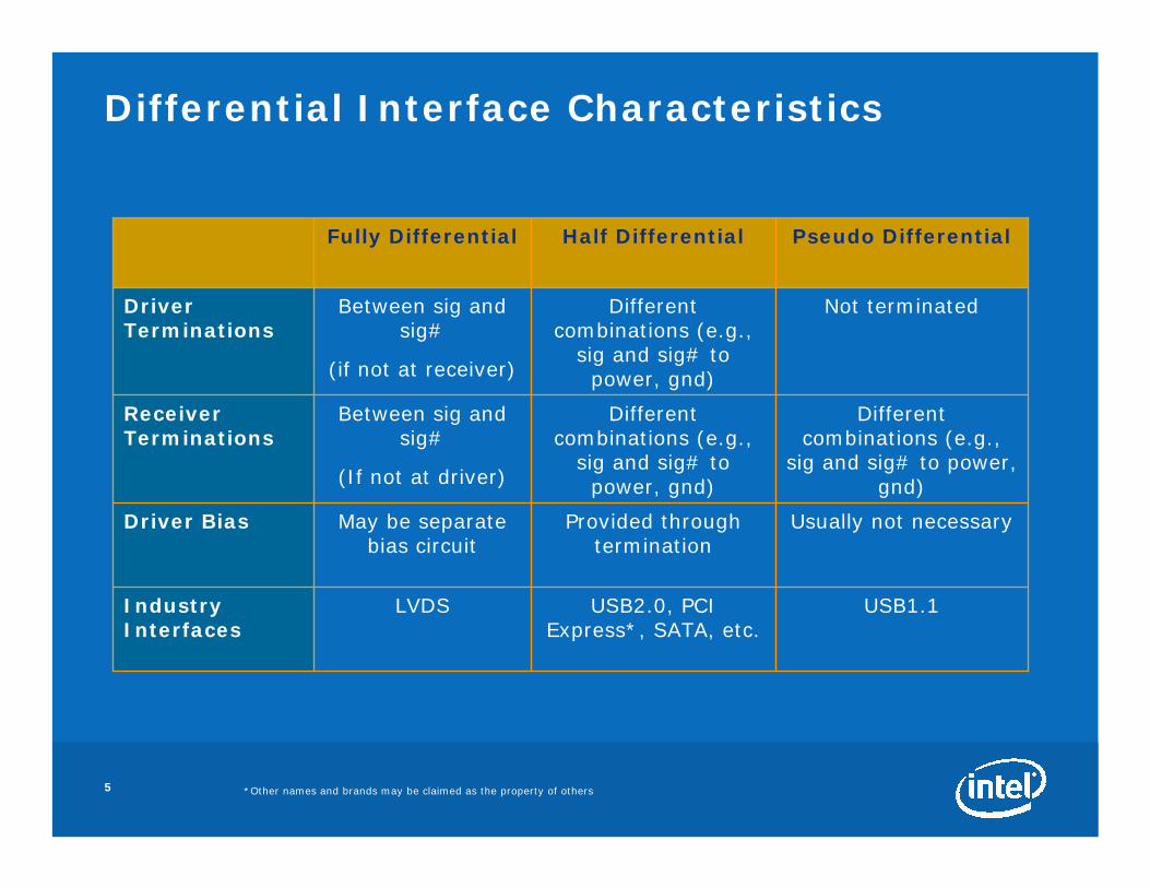
Differential Interface Characteristics
Usually not necessaryProvided through termination
May be separate bias circuit
Driver Bias
Different combinations (e.g.,
sig and sig# to power, gnd)
Different combinations (e.g.,
sig and sig# to power, gnd)
Between sig and sig#
(If not at driver)
Receiver Terminations
Not terminatedDifferent combinations (e.g.,
sig and sig# to power, gnd)
Between sig and sig#
(if not at receiver)
Driver Terminations
USB2.0, PCI Express*, SATA, etc.
Half Differential
Industry Interfaces
USB1.1LVDS
Pseudo DifferentialFully Differential
6 *Other names and brands may be claimed as the property of others
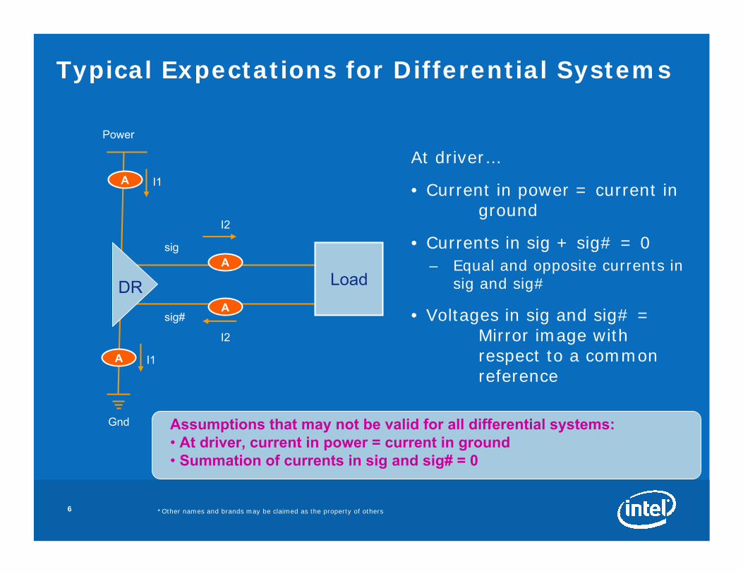
Typical Expectations for Differential Systems
Gnd
Power
A I1
A I1
A
A
Load
I2
I2
At driver…
• Current in power = current in ground
• Currents in sig + sig# = 0– Equal and opposite currents in
sig and sig#
• Voltages in sig and sig# = Mirror image with respect to a common reference
DR
sig
sig#
Assumptions that may not be valid for all differential systems:• At driver, current in power = current in ground• Summation of currents in sig and sig# = 0
7 *Other names and brands may be claimed as the property of others
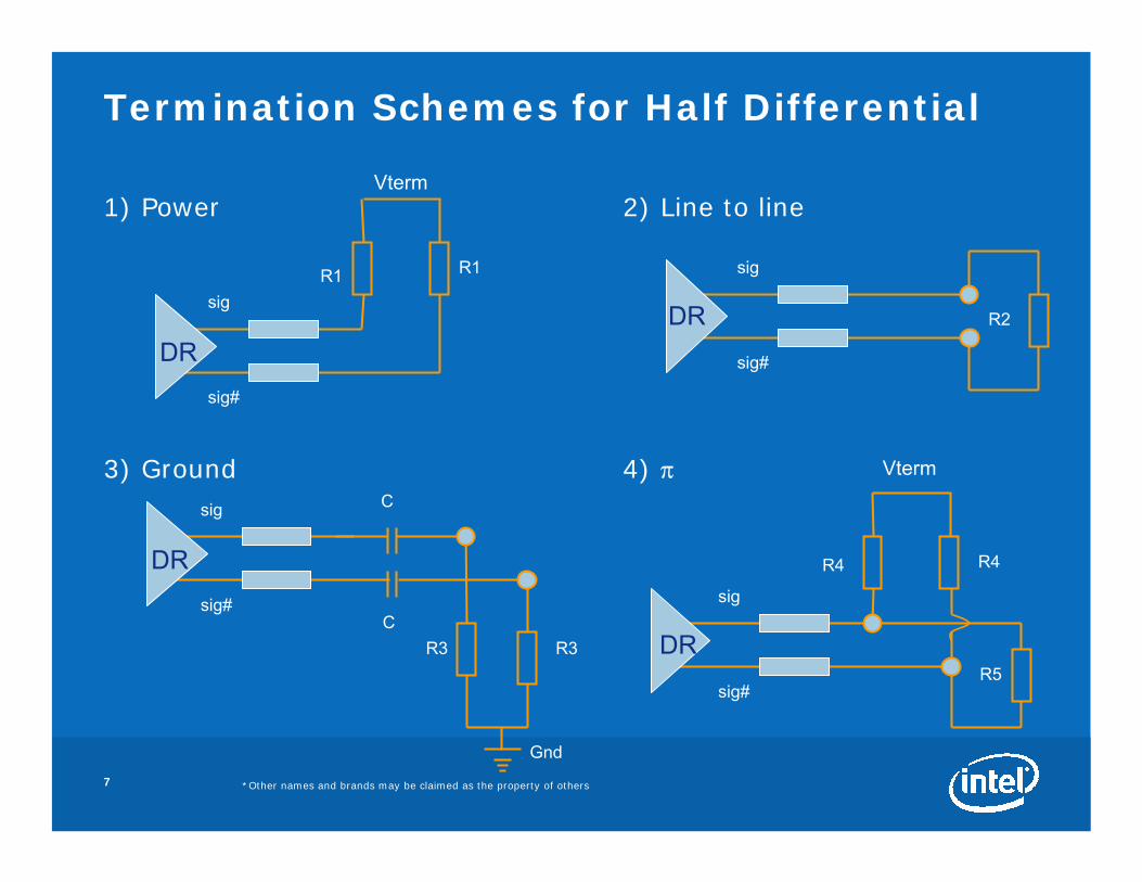
1) Power 2) Line to line
3) Ground 4) π
Termination Schemes for Half Differential
DR
sig
sig#
Vterm
R1 R1
DR
sig
sig#
Vterm
R4 R4
DR
sig
sig#
DR
sig
sig#
R3
C
CR3
Gnd
R2
R5

8 *Other names and brands may be claimed as the property of others
Termination #1: Power
Io_in
Io_in#
Io_out
REF
VtermVR
55Ω 55Ω
Io_out#
Vcc
Gnd
I
55Ω 55Ω
Vreg
Box is an S-parameter-based model with power, signal ports generated by PowerSI
Vreg model: 1.25 V, 5 nH, 7.8 mΩ
REF is a single,arbitrary reference node
PDN+ IO

9 *Other names and brands may be claimed as the property of others
Normal Operating Condition
Difference Current: Large DC, Small AC
Current (vssq)≠
Current (vccq)
Currents in Tlines: Summation ≠ 0 (1)
Voltages in Tlines
(1) Majority of return current is through ground, a net DC return current

10 *Other names and brands may be claimed as the property of others
Driver Power On/off
Difference Current : Large DC & AC
Current (vssq)≠
Current (vccq)
Currents in Tlines: Summation ≠ 0
Voltages in Tlines
11 *Other names and brands may be claimed as the property of others
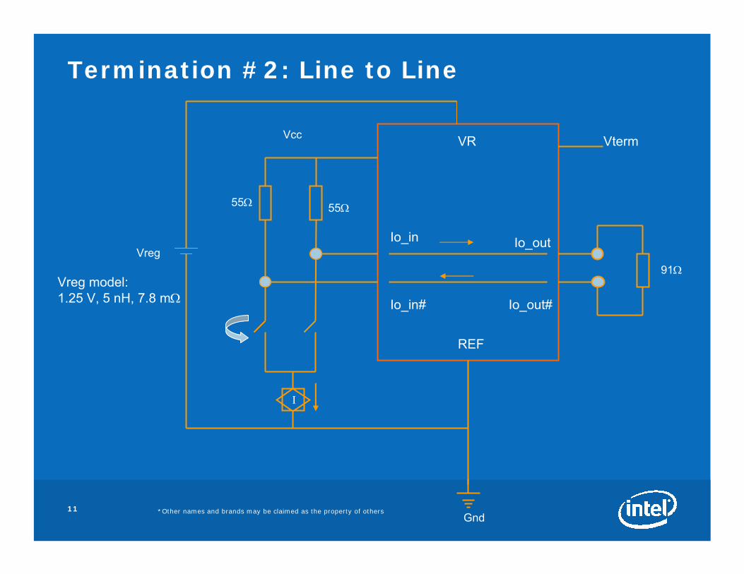
Termination #2: Line to Line
REF
VtermVR
91Ω
Vcc
I
55Ω 55Ω
Vreg
Gnd
Io_in
Io_in#
Io_out
Io_out#
Vreg model: 1.25 V, 5 nH, 7.8 mΩ
12 *Other names and brands may be claimed as the property of others
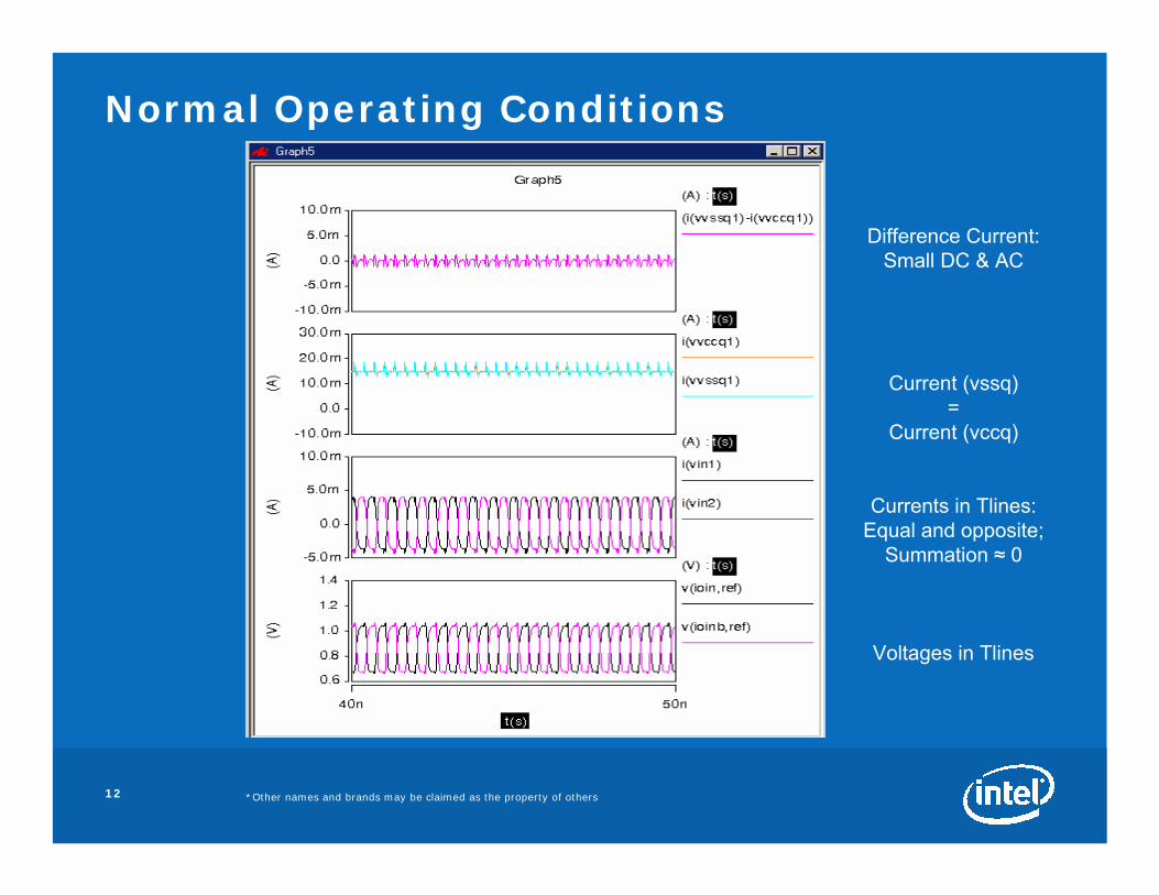
Normal Operating Conditions
Difference Current: Small DC & AC
Current (vssq)=
Current (vccq)
Currents in Tlines:Equal and opposite;
Summation ≈ 0
Voltages in Tlines

13 *Other names and brands may be claimed as the property of others
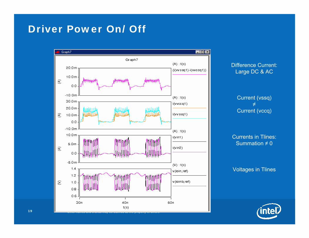
Driver Power On/off
Difference Current: Large DC & AC
Current (vssq) ≠
Current (vccq)
Currents in Tlines:Summation eventually ≈ 0
Voltages in Tlines with change in common
reference

14 *Other names and brands may be claimed as the property of others
Termination #3: Ground
Io_in
Io_in#Io_out
REF
VtermVR
55 Ω
Io_out#
Vcc
I
55 Ω 55 Ω
Vreg
Vterm
Gnd
55 Ω
50 pF
50 pF
Vreg model: 1.25 V, 5 nH, 7.8 mΩ

15 *Other names and brands may be claimed as the property of others
Normal Operating Conditions
Difference Current: Small DC & AC
Current (vssq)=
Current (vccq)
Currents in Tlines:Equal and opposite;
Summation ≈ 0
Voltages in Tlines

16 *Other names and brands may be claimed as the property of others
Driver Power On/off
Difference Current: Large DC & AC
Current (vssq)≠
Current (vccq) (1)
Currents in Tlines:Summation ≠ 0
Voltages in Tlines
(1) Currents will be equal depending on the cap charge up time, and cap value

17 *Other names and brands may be claimed as the property of others
Termination #4: π
Io_in
Io_in#
Io_out
REF
VtermVR
64.5 Ω
64.5Ω
Io_out#
Vcc
Gnd
I
55 Ω 55 Ω
Vreg309 Ω
Vreg model: 1.25 V, 5 nH, 7.8 mΩ

18 *Other names and brands may be claimed as the property of others
Normal Operating Conditions
Difference Current: Large DC, Small AC
Current (vssq)≠
Current (vccq)
Currents in Tlines:Summation ≠ 0
Voltages in Tlines
19 *Other names and brands may be claimed as the property of others
Driver Power On/Off
Difference Current: Large DC & AC
Current (vssq)≠
Current (vccq)
Currents in Tlines:Summation ≠ 0
Voltages in Tlines
20 *Other names and brands may be claimed as the property of others
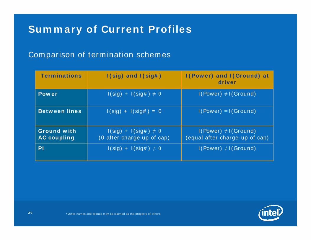
Summary of Current Profiles
Comparison of termination schemes
I(Power) ≠ I(Ground) (equal after charge-up of cap)
I(sig) + I(sig#) ≠ 0(0 after charge up of cap)
Ground with AC coupling
I(Power) = I(Ground) I(sig) + I(sig#) = 0Between lines
PI
Power
Terminations
I(Power) ≠ I(Ground) I(sig) + I(sig#) ≠ 0
I(Power) ≠ I(Ground) I(sig) + I(sig#) ≠ 0
I(Power) and I(Ground) at driver
I(sig) and I(sig#)

21 *Other names and brands may be claimed as the property of others
Significance of Current Profiles
• I(sig) and I(sig#) at driver– For half differential driver, the currents in the lines may or may not be
equal and opposite. – In normal operation, when I(sig) ≠ I(sig#)
• AC amplitude may be equal but centered around some DC value• Net non-zero DC return current
– In the driver on/off scenario, summation of I(sig) and (sig#) may result in net DC+AC current
• I(power) and I(ground) at driver– In normal operation , when I(power) ≠ I(ground), some DC shift is present
• AC current may be equal– Consider these currents in the driver on/off scenario
• di/dt will be different for power and ground in this case
22 *Other names and brands may be claimed as the property of others
Observations re Energy in PDN and Noise
• Half differential driver designs utilize a current source
• High-frequency energy in Power Delivery Network (PDN) is small compared to that in driver power on/off scenario
• Power delivery solution space (die decoupling, package and board) depends on di/dt
• Noise produced in normal operating condition is smaller than that for driver power on/off condition
• Worst case occurs when driver power on/off cycles occur at resonant frequency of the PDN

23 *Other names and brands may be claimed as the property of others
Modeling Differential Systems
• Different modeling approaches for half differential driver– Transistor models– Icc(t) method– IBIS models
• In a differential system, each modeling approach needs to address– Termination schemes’ dependence on system currents
• Currents in power and ground• Currents in sig and sig#
– The solution space is dependent on the currents
24 *Other names and brands may be claimed as the property of others
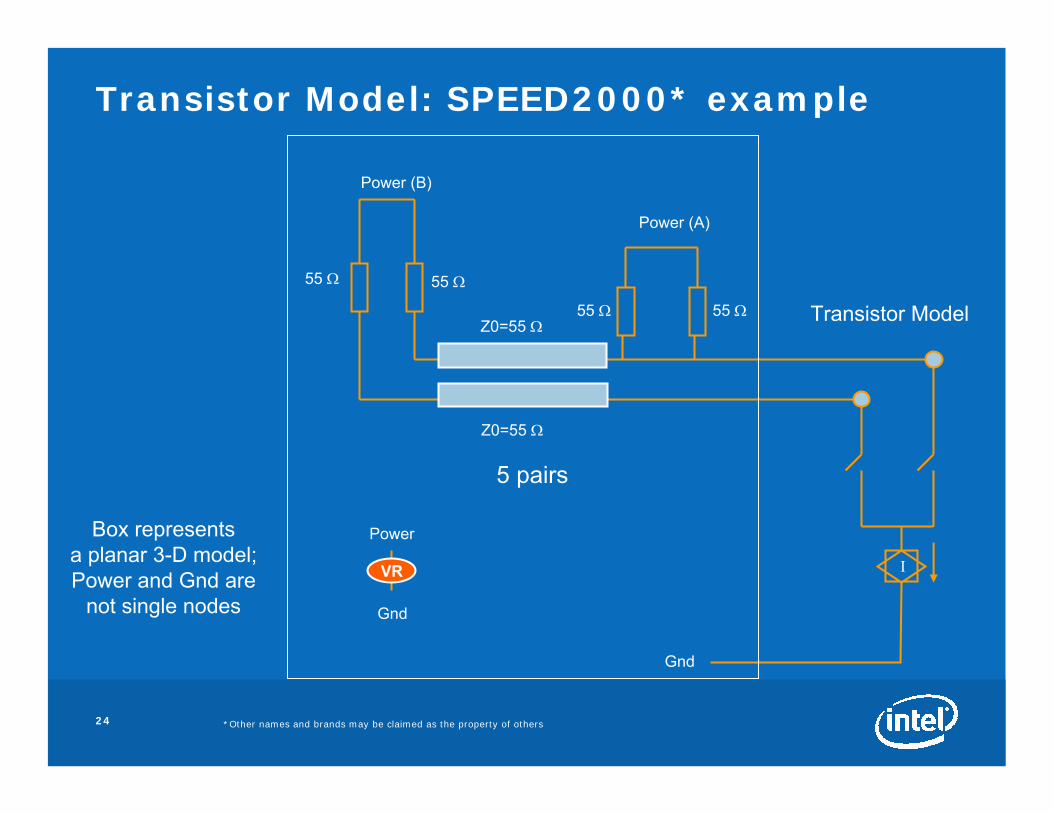
Transistor Model: SPEED2000* example
I
55 Ω55 Ω
Power (B)
Power (A)
55 Ω 55 Ω
Z0=55 Ω
Z0=55 Ω
5 pairs
Power
Gnd
VR
Gnd
Box representsa planar 3-D model;Power and Gnd are
not single nodes
Transistor Model

25 *Other names and brands may be claimed as the property of others
Sigrity SPEED2000* + Synopsys HSPICE* In Co-simulation
1.41v
1.145 v1.1 v
0.94 v
1.52 v
Noise at driver (A)
Noise at termination (B)
Driver power on/off event

26 *Other names and brands may be claimed as the property of others
Contemporary Icc(t) methods
• Typical Icc(t) approach assumes equal currents in power and ground
• Termination schemes MATTER when computing Icc(t)
• Currents in power and ground may or may not be equal
• Monitoring Ivcc and Ivss a must
Vcc
PDN Model
Gnd
Icc

27 *Other names and brands may be claimed as the property of others
Icc(t): Proposed Method
I
RR
R R
A
A I2
Z0
Z0
I1
Gnd
V1
V2
Transistor model
Driver
Termination

28 *Other names and brands may be claimed as the property of others
Icc(t) for 5 Buffers
Current in power
Current in ground
Driver power on/off event

29 *Other names and brands may be claimed as the property of others
Icc(t) Model: SPEED2000* example
Power (B)
55 Ω 55 Ω
Z0=55 Ω
Z0=55 Ω 5 pairs
Gnd
Power
Gnd
VR
Ivcc
Ivss
Power (A)
Box representsa planar 3-D model;Power and Gnd are
not single nodes
30 *Other names and brands may be claimed as the property of others
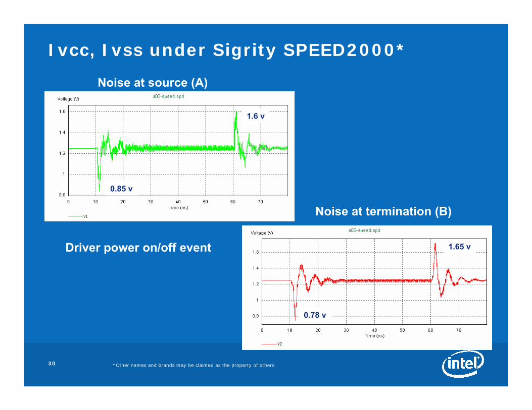
Ivcc, Ivss under Sigrity SPEED2000*
0.85 v
1.6 v
0.78 v
1.65 v
Noise at source (A)
Noise at termination (B)
Driver power on/off event

31 *Other names and brands may be claimed as the property of others
IBIS model: Sigrity SPEED2000* Example
Power (B)
55 Ω 55 Ω
Z0=55 Ω
Z0=55 Ω 1 pairIBIS* Model
Power (A)
Gnd
gnd gc
pc pu
Power
Gnd
VR
out
Box representsa planar 3-D model;Power and Gnd are
not single nodes

32 *Other names and brands may be claimed as the property of others
Normal Operation
Current in Power
≠Current in Ground
Summation of currents in transmission lines ≠ 0
Driver Currents

33 *Other names and brands may be claimed as the property of others
Driver Power On/Off
• For optimum power delivery system design, driver power on/off behavior of the buffer must be analyzed
• For IBIS*, the output only model cannot be switched off– Removing power from the buffer may not be accurate
• I/O model can be powered off through the Enable control– Implementation is tool-dependent

34 *Other names and brands may be claimed as the property of others
Conclusions
• For half differential system– Currents in differential lines are not always equal and opposite– Currents in power and ground are not always equal– Termination schemes play an important role
• For differential systems, power delivery design must consider– Normal operation vs. power on/off events– Decoupling solutions to mitigate worst case operating conditions
• Different modeling approaches need to accommodate this behavior
• Key questions for industry– Do today’s tools support driver power on/off event simulations? – Can IBIS* be used reliably for driver power on/off analyses?– Does BIRD95 include all the data needed for this kind of analysis?
35 *Other names and brands may be claimed as the property of others
Backup
36 *Other names and brands may be claimed as the property of others
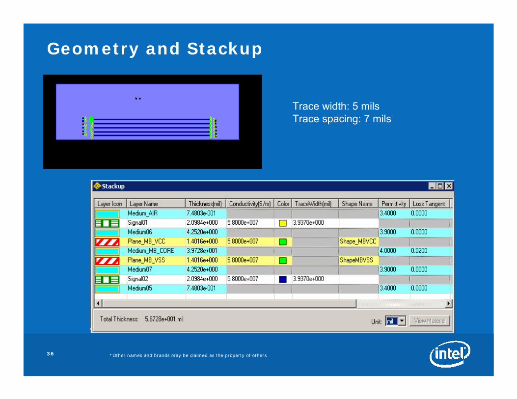
Geometry and Stackup
Trace width: 5 milsTrace spacing: 7 mils
37 *Other names and brands may be claimed as the property of others
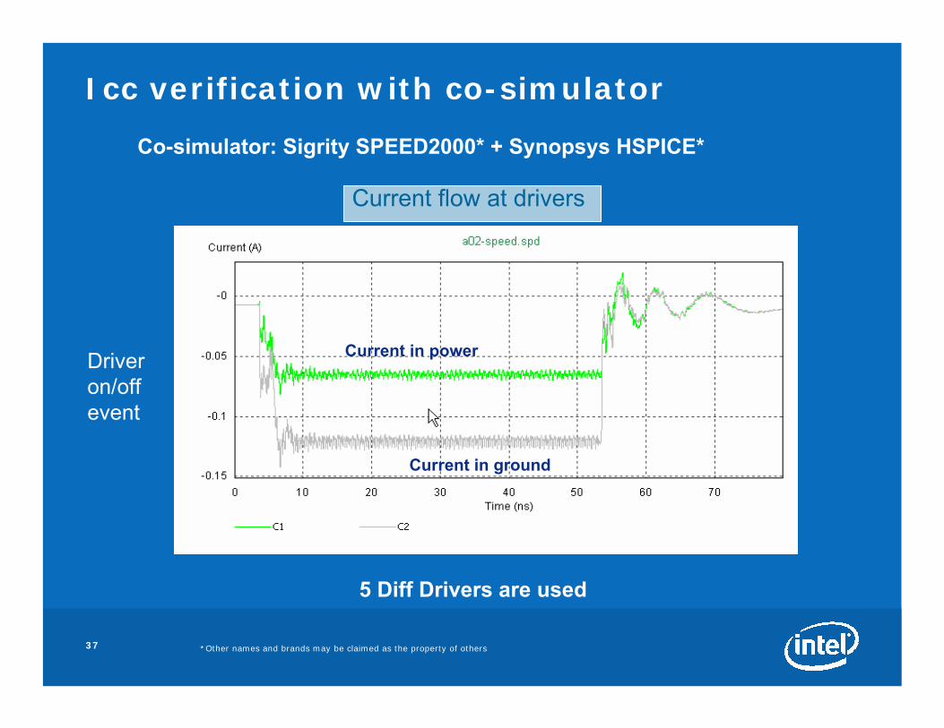
Icc verification with co-simulator
5 Diff Drivers are used
Co-simulator: Sigrity SPEED2000* + Synopsys HSPICE*
Current in power
Current in ground
Driver on/offevent
Current flow at drivers