diffraction contrast imaging - - simulation, education
TRANSCRIPT
Diffraction contrast imagingDiffraction contrast imaging
Lecture 13Lecture 13
Weak beam dark field imagingWeak beam dark field imaging
Simulation of diffraction contrastSimulation of diffraction contrast

Weak beam dark field imagingWeak beam dark field imaging

Weak beam dark field imagesWeak beam dark field images
Goal: Goal: ‘‘high resolutionhigh resolution’’diffraction contrast image diffraction contrast image of defectsof defects
Method: establish a Method: establish a kinematical condition kinematical condition (large (large ss) )
This gives a small This gives a small ξξeffeff
Result is a narrow Result is a narrow dislocation image (since dislocation image (since this is proportional to this is proportional to ξξeffeff))

Weak beam dark field imagesWeak beam dark field images
Why highWhy high--resolution resolution images?images?
Often want to look at:Often want to look at:–– Jogs & kinksJogs & kinks
–– SSeparation between partial eparation between partial dislocationsdislocations
–– Interaction between Interaction between dislocations dislocations
–– Interaction with other Interaction with other defects & precipitatesdefects & precipitates
Again, these images can Again, these images can help correlate specifics of help correlate specifics of dislocation motion with dislocation motion with overall plastic deformation overall plastic deformation responseresponse

Weak beam dark field imagingWeak beam dark field imaging
By setting By setting ss ‘‘largelarge’’ most of the most of the sample is sample is notnot oriented in a oriented in a strong Bragg conditionstrong Bragg condition
However, defect locally bends However, defect locally bends planes back to Bragg angleplanes back to Bragg angle
The region over which this The region over which this occurs is very small, as the occurs is very small, as the strain needed must be largestrain needed must be large
Thus the defect image is quite Thus the defect image is quite narrownarrow
The image The image ‘‘peakpeak’’ is thus close to is thus close to the dislocation corethe dislocation core
–– Will switch with sign of gWill switch with sign of g

Weak beam dark field imagingWeak beam dark field imaging
Steps:Steps:
1.1. Establish two beam Establish two beam condition withcondition with ss slightly slightly greater than zerogreater than zero
2.2. Tilt the strong Tilt the strong gg to the optic to the optic axis using dark field tiltsaxis using dark field tilts
•• You will note that it becomes You will note that it becomes quite dimquite dim
•• You will also see 3g become You will also see 3g become strongstrong•• This is purely a geometric This is purely a geometric
effecteffect
3.3. Insert objective aperture & Insert objective aperture & check centeringcheck centering
4.4. Now both BF & WBDF are Now both BF & WBDF are well establishedwell established
Weak beam dark field imagingWeak beam dark field imaging
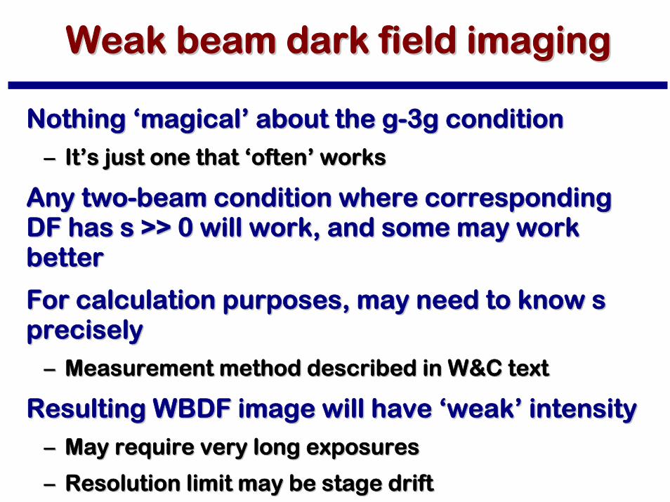
Nothing Nothing ‘‘magicalmagical’’ about the gabout the g--3g condition3g condition
–– ItIt’’s just one that s just one that ‘‘oftenoften’’ worksworks
Any twoAny two--beam condition where corresponding beam condition where corresponding DF has s >> 0 will work, and some may work DF has s >> 0 will work, and some may work betterbetter
For calculation purposes, may need to know s For calculation purposes, may need to know s preciselyprecisely
–– Measurement method described in W&C textMeasurement method described in W&C text
Resulting WBDF image will have Resulting WBDF image will have ‘‘weakweak’’ intensityintensity
–– May require very long exposuresMay require very long exposures
–– Resolution limit may be stage driftResolution limit may be stage drift

Weak beam dark field imagingWeak beam dark field imaging
A bit of theoryA bit of theory
Resulting image largely insensitive to Resulting image largely insensitive to ξξeffeff
Image is Image is ‘‘kinematicalkinematical’’
Ig= φ
g
2
=πtξ
g
⎛
⎝⎜
⎞
⎠⎟
2sin2 πs
efft( )
πseff( )2
seff
= s2 +1
ξg
2
If s 0, then seff
≈ s
I ∝sin2 πs
zt( )
πsz( )2

Weak beam dark field imagingWeak beam dark field imaging
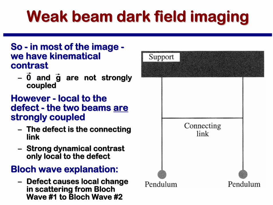
So So -- in most of the image in most of the image --we have kinematical we have kinematical contrastcontrast
–– 0 and g are not strongly 0 and g are not strongly coupledcoupled
However However -- local to the local to the defect defect -- the two beams the two beams arearestrongly coupledstrongly coupled
–– The defect is the connecting The defect is the connecting linklink
–– Strong dynamical contrast Strong dynamical contrast only local to the defectonly local to the defect
Bloch wave explanation:Bloch wave explanation:–– Defect causes local change Defect causes local change
in scattering from Bloch in scattering from Bloch Wave #1 to Bloch Wave #2Wave #1 to Bloch Wave #2
Weak beam dark field imagingWeak beam dark field imaging
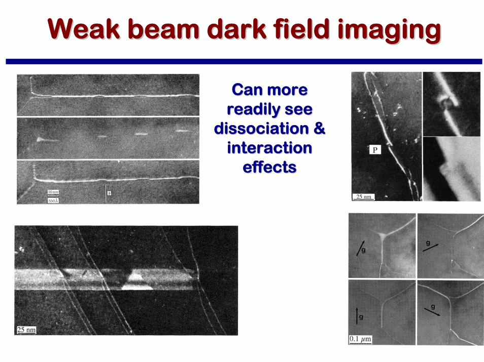
Can more Can more readily see readily see
dissociation & dissociation & interaction interaction
effectseffects
Weak beam dark field imagingWeak beam dark field imaging
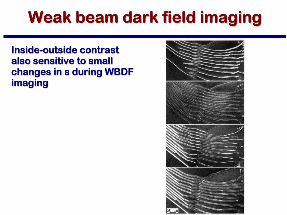
InsideInside--outside contrast outside contrast also sensitive to small also sensitive to small changes in s during WBDF changes in s during WBDF imagingimaging

Weak beam dark field imagingWeak beam dark field imaging
Many more fringes seen in Many more fringes seen in SF images SF images
Spacing very sensitive to Spacing very sensitive to ss

Weak beam dark field imagingWeak beam dark field imaging
Strong effect on thickness Strong effect on thickness fringe spacing as wellfringe spacing as well
Large Large ss reduces effective reduces effective extinction distance extinction distance ξξeffeff
Simulation of diffraction Simulation of diffraction contrastcontrast
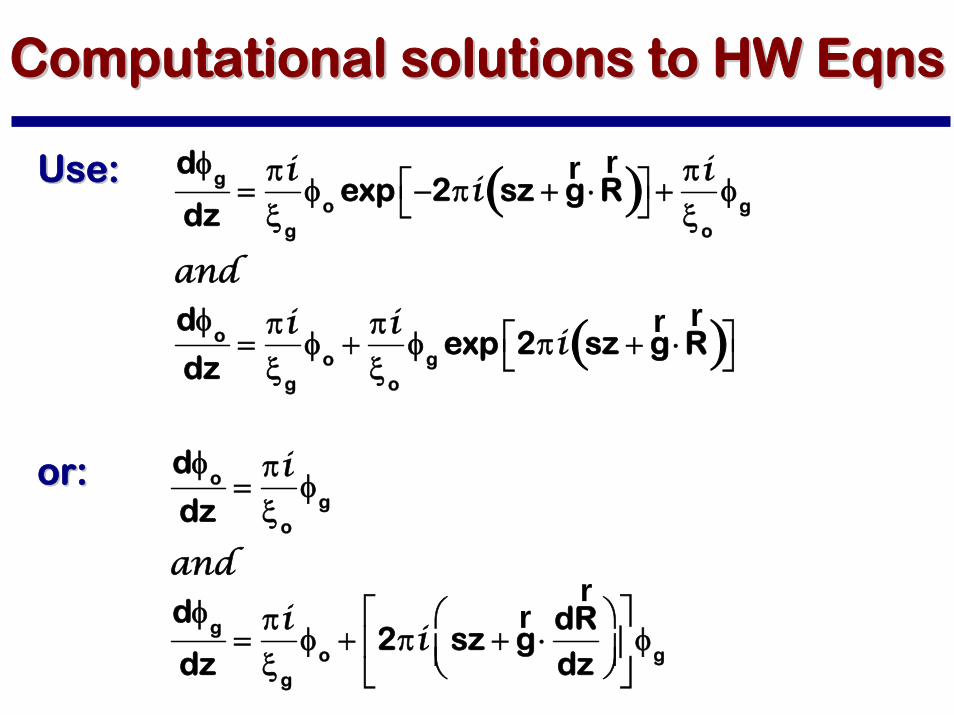
Computational solutions to HW Computational solutions to HW EqnsEqns
Use:Use:
or:or:
dφg
dz=πiξ
g
φo
exp −2πi sz +rg ⋅
rR( )⎡
⎣⎤⎦ +
πiξ
o
φg
anddφ
o
dz=πiξ
g
φo+πiξ
o
φg
exp 2πi sz +rg ⋅
rR( )⎡
⎣⎤⎦
dφo
dz=πiξ
o
φg
anddφ
g
dz=πiξ
g
φo+ 2πi sz +
rg ⋅
drR
dz
⎛
⎝⎜⎞
⎠⎟⎡
⎣⎢
⎤
⎦⎥φg
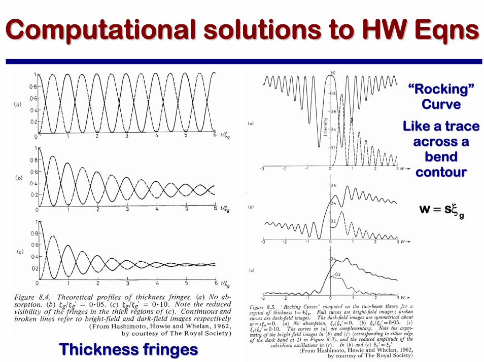
Thickness fringesThickness fringes
““RockingRocking””CurveCurve
Like a trace Like a trace across a across a
bend bend contourcontour
w = sξ
g
Computational solutions to HW Computational solutions to HW EqnsEqns

Obviously, can produce Obviously, can produce simulated images by simulated images by calculating calculating φφoo and and φφgg along along each columneach column
Computational solutions to HW Computational solutions to HW EqnsEqns
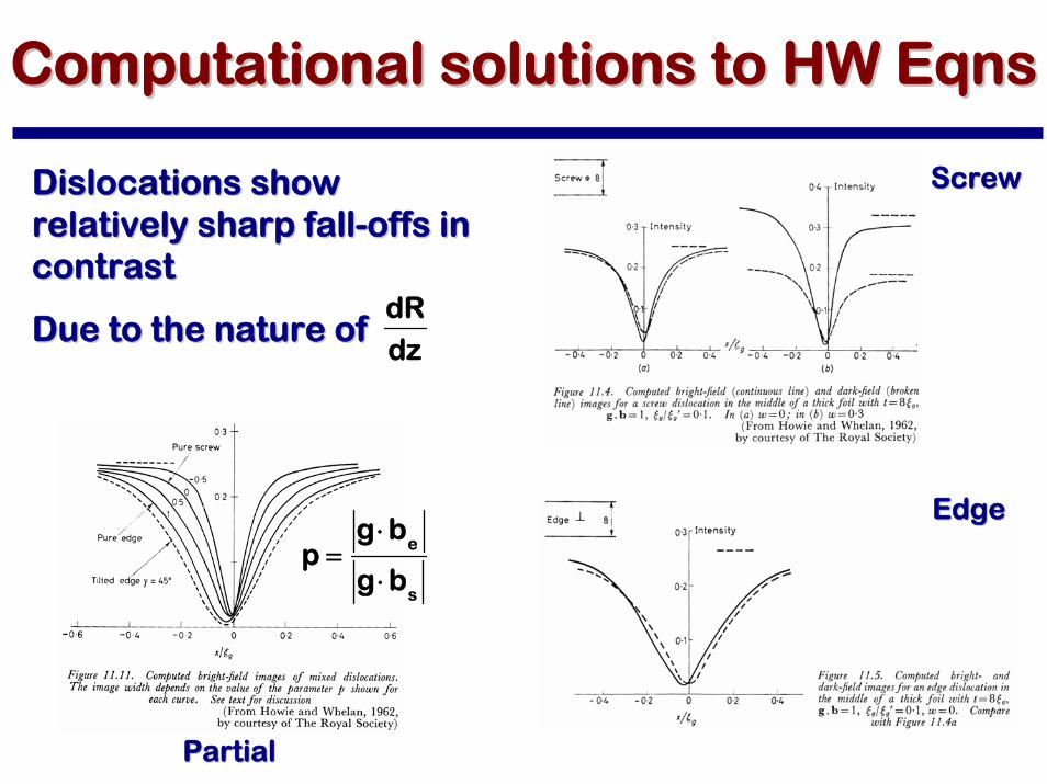
ScrewScrew
EdgeEdge
PartialPartial
p =g ⋅b
e
g ⋅bs
Dislocations show Dislocations show relatively sharp fallrelatively sharp fall--offs in offs in contrastcontrast
Due to the nature of Due to the nature of
dRdz
Computational solutions to HW Computational solutions to HW EqnsEqns

““A method for simulating electron microscope A method for simulating electron microscope dislocation images,dislocation images,”” SchublinSchublin R., R., StadalmannStadalmann P., P., Materials Science and Engineering, A 164 (1993) Materials Science and Engineering, A 164 (1993) 378378--378378
Computed Electron Micrographs and Defect Computed Electron Micrographs and Defect IdentificationIdentification, , Head A.K., Humble P., Head A.K., Humble P., ClarebroughClarebrough L.M., Morton A.J. L.M., Morton A.J. andand ForwoodForwoodC.T., C.T., NorthNorth--Holland Publishing Company, Holland Publishing Company, Amsterdam, 1973Amsterdam, 1973
CUFOUR:CUFOUR:
--http://cecm.insahttp://cecm.insa--lyon.fr/CIOL/cufour.htmllyon.fr/CIOL/cufour.html
Computational solutions to HW Computational solutions to HW EqnsEqns

Obviously, can produce Obviously, can produce simulated images by simulated images by calculating calculating φφoo and and φφgg along along each columneach column
Computational solutions to HW Computational solutions to HW EqnsEqns

Computational solutionsComputational solutions to HWto HW EqnsEqns
““SIMCONSIMCON””
A program that allows A program that allows one to use the output one to use the output form FEM modeling to form FEM modeling to generate simulated generate simulated diffraction contrastdiffraction contrast
K. K. JanssensJanssens, , UltramicroscopyUltramicroscopy, 45, 323, , 45, 323, 1992.1992.
J. Demarest, et al., J. Demarest, et al., ApplAppl. . Phys. Phys. LettLett., 77, 412, 2000.., 77, 412, 2000.
Li, et al., Li, et al., ApplAppl. Phys. . Phys. LettLett. . 8787, 222111, 2005., 222111, 2005.