diffusion-limited reactions in spherical cavities€¦ · diffusion-limited reactions in spherical...
TRANSCRIPT
Diffusion-limited reactions in spherical cavities Amy L. R. Bug, Elizabeth L. Grossman, and Dane D. Morgan III Department of Physics and Astronomy, Swarthmore College, Swarthmore, Pennsylvania 19081
Bruce J. Berne Department of Chemistry, Columbia University, New York, New York 10027
(Received 4 October 1991; accepted 6 March 1992)
We study a quenching reaction occurring at sinks within a spherical cavity and at the cavity surface. One may think of reactions at these two, distinct locations as two, coupled reactive channels. Reactions of the type D* + A + D + A are studied in the limit of nondilute A, present at both locations, and dilute D, present within the cavity. We use a Monte Carlo algorithm to compute mean rates, pseudo-first-order rates and branching ratios, and compare with results obtained by assuming that the two reactive channels operate in parallel. The ratio of activities of the two channels are varied; static and moving sinks are studied. We discuss an application to the determination of pore structure by NMR (nuclear magnetic resonance).
I. INTRODUCTION
It has been appreciated for many years that some bimo- lecular reactions are enhanced by confining one or both rea- gents to a restrictive geometry. The importance, for biologi- cal systems, of a diffusion space of reduced volume or dimensionality (surface diffusion) was first discussed in de- tail by Adam and Delbruck. ’ Micelles solvate and/or local- ize donors and acceptors in their interiors or on their sur- faces, as in irreversible quenching reactions of the type D* + A-D + A studied by Hatlee and co-workers.2 In studies on reactions in the presence of surfactant aggre- gates3” workers found the existence of new reactive chan- nels, which typically show pseudo-first-order kinetics. Large enhancements in a reaction rate or suppression of an un- wanted backreaction-useful, e.g., for the purpose of storing photochemical energy,‘** may also occur. On the other hand, reaction rates may be used as a probe of the shape of surfactant aggregates.‘.” The theory of reactions in confin- ing pores has a major application to heterogeneous catalysis; a classic work by Aris’ ’ relates the theory of heat and mass transport to reactions in various, realistic, pellet geometries.
A number of theoretical studies on micellar kinetic pro- cesses have appeared. Analytical solutions of the diffusion equation on or within a sphere with absorbing boundaries near the surfacei2-i4 or at the cavity center”2*‘5 give the rates which describe the multiple-exponential decay of concentra- tion. Given experimental lifetimes, diffusion coefficents may be predicted. l6 Some studies’7-‘9 begin with rates for quenching in the micellar interior or surface, and for escape or re-entry of the donors. These studies test various models for the spatial partitioning of quenchers in, on, or near the micelles.6 Given experimental parameters such as viscosity within micelles, bulk reaction rates, and populational pa- rameters for micelles, these theories may predict a decay in the concentration of excited donors which is in fair agree- ment with experimental results.” If parameters of the theo- ry are fit, agreement can be excellent.” Computational stud- ies will be discussed below. In all of these modeling studies,
reaction may occur at only one type of site in the system: either on sinks within a cavity, or at a cavity surface, or at a buried active site.
Here we study an irreversible, diffusion-limited, quenching reaction within a spherical cavity of micellar size. In the theoretical treatments mentioned above, competition between different reactive surfaces for reagent is not taken into account. For example, the statistics governing the distri- bution of sinks within the micelles are used to predict a net rate of reaction for the system. Early in the calculation, the rate for reaction in a micelle containing n sinks is assumed to be n times the rate for a micelle containing a single sink. This approximation, which holds in the dilute sink limit, treats the surface of each sink as a separate, uncoupled, reactive channel. In other words, it says that the bimolecular rate constant is independent of sink concentration. However, a concentration dependence of this rate is axiomatic within the literature on homogeneous systems of spherical sinks.” For example,21 steady-state rate constants behave as k, [ 1 + m + ord (4) ] for perfectly absorbing sinks of vol- ume fraction 4; k, is the Smoluchowski22 bimolecular rate of 4z-Db, with D the diffusion constant for reagent and b the sink radius. If one considers the decay, with time, of an ini- tial concentration, the steady-state result can be equated with a mean rate of quenching with time.23 Various studies concur that rates are around twice the Smoluchowski value for 4 = 0.1. Since this is a realizable concentration for many types of reactions within micelles, one should see this effect. In general, the cooperativity which occurs in an n-sink sys- tem produces a rate which exceeds n times the single-sink rate. For example, fluorescence intensities of lysopyrene quenched by pyranine at the surface of DODAC vesicles are predicted by Nomura et al. by assuming that quenching rates scale linearly with pyranine concentration. (This linearity is embodied in the Stern-Volmer formula.24325 ) However, cal- culated intensities fall systematically below experiment (Ta- ble II of Ref. 8) as pyranine concentration increases, as we might expect.
8840 J. Chem. Phys. 96 (12), 15 June 1992 0021-9606/92/l 28840-l 3$06.00 @ 1992 American institute of Physics

Bug etai: Diffusion-limited reactions in spherical cavities 8841
In this paper, we study the enhancement of the diffu- sion-limited reaction which occurs by allowing reaction to occur simultaneously at two different types of site. These are (i) at the surface of one or more sinks within the cavity volume and (ii) at the cavity surface. By “enhancement,” we mean the factor by which the rate of reaction exceeds the sum of the rates that we would calculate if one of the two types of sites were rendered inert. We compute both a mean and a pseudo-first-order rate; these are defined in Sec. II below. We find that enhancements greater than l/3 can be seen in Monte Carlo (MC) data from the quenching of do- nors 5.0 A in diameter by like-sized spheres at an effective volume fraction of approximately 0.2. One implication is that, if one is interested in catalyzing such a reaction with high efficiency in a micellar system or a microporous solid, one might try to introduce acceptors (possibly, two differ- ent, accepting species) which sit at the two different loca- tions.
The paper is organized as follows. In Sec. II, we describe the quenching reaction to be studied and the rates to be cal- culated. We also discuss an analytically solvable case; that of a spherical sink at the micelle center. (This case is often used as a point of reference, despite the fact that there are good reasons to assume that a mobile sink will typically avoid this location.13 ) In Sec. III, we digress to the case of a two-di- mensional, model capillary with absorbing sinks at the walls, to observe the effect that competition between walls has on a rate constant. We discuss an application other than a chemi- cal reaction: the use of spin-lattice relaxation times in NMR (nuclear magnetic resonance) to deduce the structure of pores within microporous solids. In Sec. IV, we present the results of MC simulations of a model micelle containing sev- eral sinks. The reaction is primarily diffusion limited, though the ratio of reactivities of sinks and the cavity wall are varied to study the important case in which the branch- ing ratio is approximately unity. Both static and moving sinks are studied and rates are averaged over sink configura- tions. Our goal is to determine the enhancement of reactivity when the dispersed sinks and the cavity walls compete to absorb reagent.
II. QUENCHING REACTION IN A SPHERICAL CAVITY
Consider a spherical cavity in which a species D (do- nor) is free to diffuse. This molecule is modeled as a sphere; it may approach no closer than its radius to the cavity wall. It may not overlap with a second molecular species which is placed within the cavity. In a typical fluorescence quenching experiment, it is possible to insure that at most one D will be found in any spherical micelle, along with a number of mole- cules A, which serve as acceptors for an excitation of the donor.“*6 Depending on the identity of A, it is also possible to find D within the cavity, but A’s are located at the surface. One may have such a high concentration of A that the sur- face of the cavity is completely saturated.’ We propose to model an experiment in which, at an initial time, donors are photoexcited, and may be quenched by acceptors. Schemati- cally, D + D* followed by D* + A -+ D + A. Experimental- ly, one follows the intensity of fluorescence that accompa-
@ ,iiji/;, ,fo “““iii;!,; +::6J o .;-;‘I. ,,
0 ~~~~ ~:~,, 0 i: @ :‘l:iiii.:, ,, 0 ,;J ii ‘is:,,;,, @ j
C s cs
FIG. 1. Three schemes for the location of quenching surfaces within a spherical cavity. Hatched areas represent partially absorbing surfaces; un- hatched areas represent reflecting surfaces. Schemes are noted as C, accep- tors in center; S, at surface; and CS, at both locations. (The text discusses various numbers of spheres; for simplicity, three are shown in this figure.)
nies the de-excitation of D. There will, of course, be spontaneous de-excitation of D*, but this process occurs in parallel with quenching by A, so the net fluorescence rate is just a sum of the two rates.
We consider a single geometry: a spherical cavity of ra- dius R containing a certain volume fraction of spheres which are impenetrable to a single, enclosed, D molecule. Against the backdrop of this geometry, we consider three schemes for the placement of A molecules. In the first, the A mole- cules coincide with the spheres, making them quenchers (sinks) for the reagent, D*. In the second, quenching occurs at the surface of the cavity; the impenetrable spheres are, nevertheless, present so that we may compare situations in which D* has the same free volume in which to diffuse. In the third scheme, the A molecules coincide with the spheres and saturate the surface of the cavity. These will be referred to as schemes C, S, and CS, respectively, and are shown schematically, for three enclosed spheres, in Fig. 1. A given scheme determines which of the bounding surfaces merely reflect, and which quench, in the following time-dependent diffusion equation for the concentration, C(r,t) of D* within the cavity:
dc(r,t) - = DV’C( r,t) at
subject to
(1)
aW,,,f> dn =
am,,0 = o Vt - h,C(r,,O; an (2)
A development of these equations in the context of catalysis can be found in Chap. 2 of Ref. 11. In Eq. ( 1 ), D is the self- diffusion coefficient for D* within the micelle. In Eq. (2)) rQ, and rN represent any location on a quenching (we will also use the term absorbing) or reflecting surface, respectively, n is a surface normal, and h, describes the reactivity of the ith quenching surface. A vanishing h, indicates reflection, and perfect absorption implies that this number is infinite. In this case,
C( rQ,,t) = 0 (perfect absorber). (3) If l/(h &D) is very much less than the typical time that it takes for reagent to visit the ith surface; and in the extreme limit, if Eq. (3) holds, reaction of D* with that surface is considered to be d@usion limited.
J. Chem. Phys., Vol. 96, No. 12,15 June 1992

8842 Bug &al.: Diffusion-limited reactions in spherical cavities
Assume, for now, that the bounding surfaces do not change with time. A unique solution to Eqs. ( l)-( 3) corre- sponds to a given geometry as in Fig. 1. Separation of vari- ables: CE T( t)X( r), and solution of the resulting Helmholtz equation for X produces a series solution’J*26
C(r,t) = 2 B,X, (r)eeD”“. (4) ”
quencher, [ Eq. (3) 1, and that in cases S and CS, the surface of the micelle quenches with a strength hs [ Eq. (2) 1. Equa- tion ( 1) has been well studied for this geometry, and we quote the solution ‘,15 for the case of a spherically symmetric initial distribution, C( r,O).
Case C:
The eigenvalues a,, , and the associated eigenmodes X,, , de- pend on the boundary conditions, as given by the radii and placement of spheres, cavity radius, which case among C, S, or CS we choose, values of h, for absorbing surfaces, and the radius of the diffusing sphere. (The diffuser is not a point, so the bounding surfaces are not necessarily those of small spheres enclosed by a larger sphere.) The amplitudes B, are determined by the initial concentration of D*. The X,, are orthogonal for different values of n, so that
C(r,t) = 2 Bz sin[a,(r-a)] e-Da;t , (9)
n=O r with B 2 a known function of a, R, and C(r,O). It is given by Eq. (5) with X, (r) =j, (a,, r), a spherical Bessel of zeroth order. In these equations, an is the nth root of
B, = I
C(r,0)Xz(r)d3r /f
X*Xd3r. (5)
Consider the likelihood, P(t) , that D* is present in the cavity at time t
a, (R -a) cota,(R-a) = 1-G . ( >
(10)
Two limits for k. given by the transcendental Eq. (10) might be noted. In the limit of a weakly quenching reactor, which is accomplished by shrinking the central sink,
k,-= R3
for a/R(l. (11)
In the limit where the the central sink grows to fill the cavity
P(t) = s
C(r,t)d3r. (6) k,= OS-=
4R*(l -a/R)* for (1 -a/R)*l. (12)
Case S: At short times, P(t) receives contributions from many ex- ponentially decaying modes. In this limit, for diffusion-lim- ited reactions, P has alternatively been expressed as a stretched exponentia1.27~28 At long times, the likelihood will decay as a single exponential, with a relaxation time bf l/k, with k, = Da:, which corresponds to the longest time scale in Eq. (4)
C(r,t) = z Bz sin[a,(r-a)] +aa, cos[(r-a)a,]
tL=O r - Lkz2.t Xe ,
(13)
P(t)areekof as t-co. (7) This rate, k,, , is the pseudo-Jrst-order rate. In fluorescence quenching experiments, the long time decay of fluorescence typically gives an excellent fit to a single-exponential form, allowing this constant (or an analogous one which takes into account the entry and exit of quenchers from a micelle) to be computed.“*”
withBS, aknownfunctionofh,,a, R,andC(r,O) [Eq. (5)], and a,, given by
(h,R - 1 - aRaf#) sin[a,(R -a)]
+Rrr.[h,a+(l-;)] cos[a,(R-a)] =O. (14)
Two limits for k. : For the weakly quenching reactor, for all values of a/R so long as the central sink does not grow to fill the cavity
A second rate, which is commonly used in first-passage time problems,*’ is the mean rate, k. This rate (which is equivalent to the rate above for a pure, single-exponential process) is defined as
k. z 3Dh,
3a(l -a/R) fR(1 -a/R)3 for h,R < 1 - a/R.
_ (15)
l/k = s
* P(t)dt. (8) 0
The limit in which the micellar surface becomes a strong quencher yields a simple form for k,, if we make the addi- tional provision that a is close (but not equal) to R
This is the quantity that should be equated with the steady- state rate.23 It is often used, is readily calculated for reactors with simple geometries,6 and has been shown to be useful for solving problems in which the diffuser obeys a generalized (Smoluchowski) diffusion equation3’
kor!??t 4R2
A. Central sphere model: Pseudo-first-order rates Consider a single molecule A, of radius a, fixed at the
center of a sphere of radius R. In this geometry, we use a point walker, D*. Assume that in cases C and CS (as in Fig. 1, but now with only a single, central sphere), A is a perfect
so long as
h,R(l - a/R)2g1. Equation (16) neglects terms of ord( l/h,R).
Case CS:
(16)
C(r,t> = 2 BzS sin[a,(r--a)] e-Da;t (17)
n=O r with By a known function of hS, a, R, and C(r,O) [Eq. (5) 1, and a,, the nth root of
J. Chem. Phys., Vol. 96, No. 12,15 June 1992
Bug eta/.: Diffusion-limited reactions in spherical cavities 8843
a,(R-a)cota,(R-a)=(l-h,R) 1-G . ( >
(18) In the limit of a weakly quenching reactor (accomplished by both shrinking the central sink and weakening the quench- ing strength of the micellar surface),
k,,s$(h,R+G) for h,Rfa/R-=gl. (19)
In the limit in which the micellar surface becomes a strong quencher (so long as the central sink does not grow to fill the cavity)
ko = Lw
R*(l -a/R)2 so long as
h,R(l -a/R)+1. (20)
Equation(20)neglectsatermoford[l/(h,R)(l -a/R)]. The formulas above allow us to compare the pseudo-
first-order rate for scheme CS, k ,“, to the sum of the rates for schemes C and S, k,C and kz. We define the enhance- ment, Ak, , as an absolute increase in the rate
Ak, =k,CS- (k,c+k,s); the relative enhancement,
(21)
6ko = Ako/k 0” (22)
is also of interest. The task is just to solve the transcendental Eqs. ( lo), ( 14), and ( 18) as the dimensionless parameters h,R and a/R are varied. Before doing so, note that Ak, =O in the weak quenching limits, which are described by Eqs. (11),(15),and(19).Thatis,tofirstorderinh,R anda/R, the reactive channels at the surface and center of the micelle, as measured by k,, operate in parallel. In this limit of small h,, the reaction at the surface is not diffusion, but activity limited.
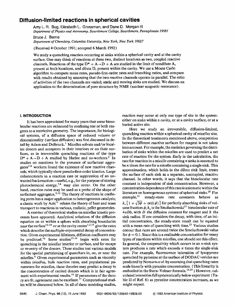
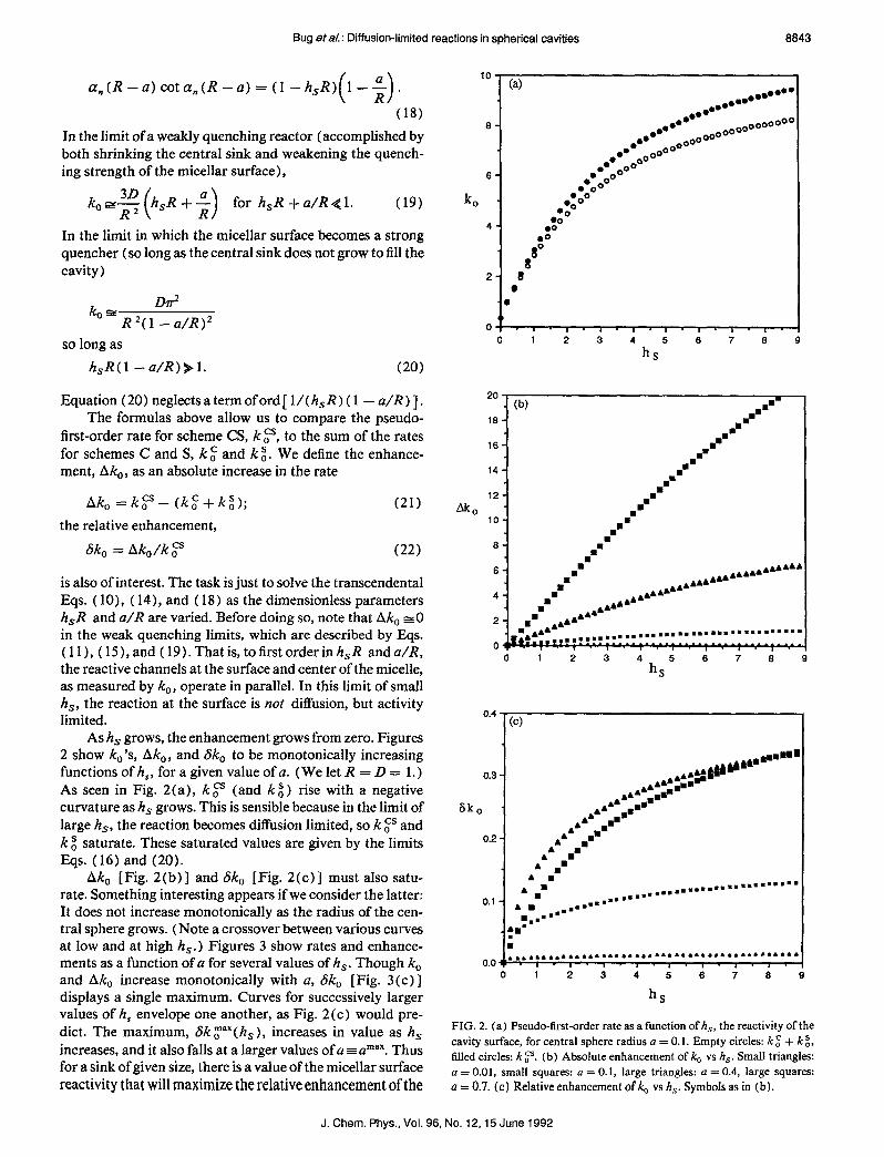
Ash, grows, the enhancement grows from zero. Figures 2 show kO’s, Ak,, and 6ko to be monotonically increasing functions of h,, for a given value of a. (We let R = D = 1.) As seen in Fig. 2(a), k 0” (and k i ) rise with a negative curvature as hs grows. This is sensible because in the limit of large hs, the reaction becomes diffusion limited, so k 7 and k 2 saturate. These saturated values are given by the limits Eqs. (16) and (20).
Ak, [Fig. 2(b)] and Sk, [Fig. 2(c)] must also satu- rate. Something interesting appears if we consider the latter: It does not increase monotonically as the radius of the cen- tral sphere grows. (Note a crossover between various curves at low and at high h,.) Figures 3 show rates and enhance- ments as a function of a for several values of h,. Though k, and Ak, increase monotonically with a, Sk, [Fig. 3(c) ] displays a single maximum. Curves for successively larger values of h, envelope one another, as Fig. 2(c) would pre- dict. The maximum, Sk r(h, ), increases in value as h, increases, and it also falls at a larger values of a z amax. Thus for a sink of given size, there is a value of the micellar surface reactivity that will maximize the relative enhancement of the
10
6
6
ko
4
(a) ...**’ l .’ l **
.a.. .
l * l * a*
ooooooo~
0 ooooo l . 0.
0000 ooooo”
0. ’ 00 oOO” .*oo 00
WOO 00 00 .O
I 00
2 0
6k
2
0
I<~, , , , , . , . , , , , , , , , 0 1 2 3 4 5
hs
6 7 8 9
*’ . (b) 18 -
I
m= I
mm n =
. . 16
I 2
/
14 1 mm
..-
12 - m
io- .mrn
2.
8- n
m .
6- n
mm .AAAAA
,....A....4
4- . n .A..
.A.. .A..
.
2- n = AA4
- ..A. A.. .A..
,.,.... -rn . . . . . . . . . . . . . . . m . . . . . . . s... 0s
0 1 2 3
4hs5 6 7 8
-’ (c) I
a*mmmml
0.3 - . ..#h” AAAAm@
AA. mm
:o . AA .A b:mmmmm
AA mm A. mm
0.2 - A A
A mm m’
A . A n
A mm A m
0.1 - * l = . . ..gm m,m,,,... ..~.~~=~m~~~~~~
..m=-
1.. ..-¤
t ’ m . . . . . . . . . . . . . . . . . . . , . , . . . . . . . . . . . . . . . . . . . . . .
.I .I .I. ) ., ., ., ., .
0 1 2 3 4 5 6 7 8
hS
FIG. 2. (a) Pseudo-first-order rate as a function of h,, the reactivity of the cavity surface, for central sphere radius a = 0.1. Empty circles: k g + k 2, filled circles: k ,“. (b) Absolute enhancement of k,, vs h,. Small triangles: a = 0.01, small squares: a = 0.1, large triangles: a = 0.4, large squares: a = 0.7. (c) Relative enhancement of ,4, vs h,. Symbols as in (b).
J. Chem. Phys., Vol. 96, No. 12,151 June 1992
8844 Bug et&: Diffusion-limited reactions in spherical cavities
(6) 0
0
40- 0
.
quenching rate. Similarly, if one is given the surface reacti- vity, there is a value of sink radius, amax that is optimal. Below, we will note that this radius varies with the surface reactivity in a way which is correlated with the branching ratio.
0 .
30 - l o
kJ . 00 .O
20 - 4 00
00 .‘o
10 - l 0O0 .*8”
As mentioned above, the enhancement saturates at a large-h, limit, which is a-dependent. When a z R, the reac- tion rates in cases C, S, and CS, per unit surface area of the wall, will be equivalent to the rates for reaction between two infinite planar walls separated by a distance R - a. Equa- tions ( 12)) ( 16), and (20) confirm this for the case of very large h,. That is,
,,,.z..m@~ e*ga1~00
9
-I 8 I I . 0.0 0.2 0.4 0.6 018 ll0 a
k;=kz- D* 4(R -a)* ’
JIcyz Dd when h,-+m, a+R. (R -a)’
(23)
Thus ” 1 (b) .
. A’
.
Sk, =Sk~(hsrco)+ (24)
for this diffusion-limited reaction between two infinitesmal- ly separated, spherical surfaces.
One can get some feeling for this enhancement by noting that k, is related to the shape of the zeroth eigenmode, Xc, and comes from a variational principle26*3 ’
k. =min Slv~lzdr = slvxo’2dr ,
SWl’dr SIX0 I2 dr
(25)
0.4 0.6 018
a
where Ic, is any function that obeys Eqs. (l)-(3) and the integral is over the cavity. So, the ground state, X0, is the solution to the correct equation, with the correct boundary conditions, which minimizes the mean squared curvature. If one takes a given geometry with a reflecting and a quenching surface, and converts both to quenchers, the mean curvature of the ground state solution rises. In the case of two planar walls and perfect quenching, it doubles. But k, goes as the square of the curvature, so the rate is enhanced by a factor of ( l/2) [Eq. (24) ] over the sum of the rates of the two, com- peting reactions. This is an upper limit for Sk, for the cen- tral-sphere model. Further, one feels that it might also be an upper limit for enhancement due to competition between arbitrarily placed spheres and a cavity wall, and even for the competition between the multiple spheres in a cavity or in a homogeneous system.
“.WI , , . ,
0.0 0.2 0.4 0.6 0:s 1to
a
One might wonder if the value of the sink radius, amax, at which 6k, has its maximum, varies with h, in a way which can be predicted by the branching ratio, B. That is, since competition between reactive surfaces produces enhance- ment, perhaps amax occurs where B z 1. We define B as the ratio of reagent quenched by the central sink to that quenched at the surface in case CS. This ratio of reactive fluxes is
(26) FIG. 3. (a) Pseudo-first-order rate as a function of a, for h, = 1. Symbols as in Fig. Z(a). (b) Absolute enhancement of k0 vs a. Small triangles: h, = 0.1, small squares: h, = 1, large triangles: h, = 3, large squares: h, = 9. (c) Relative enhancement of & vs a. Symbols as in (b).
B = JVC(a,t) Ia2 IVC(R,t) IR * .
To be consistent, we investigate the long time approxima- tion, in which pseudo-first-order kinetics occurs. In this lim- it, B is time independent and is given by
J. Chem. Phys., Vol. 96, No. 12,15 June 1992
Bug &al.: Diffusion-limited reactions in spherical cavities 8845
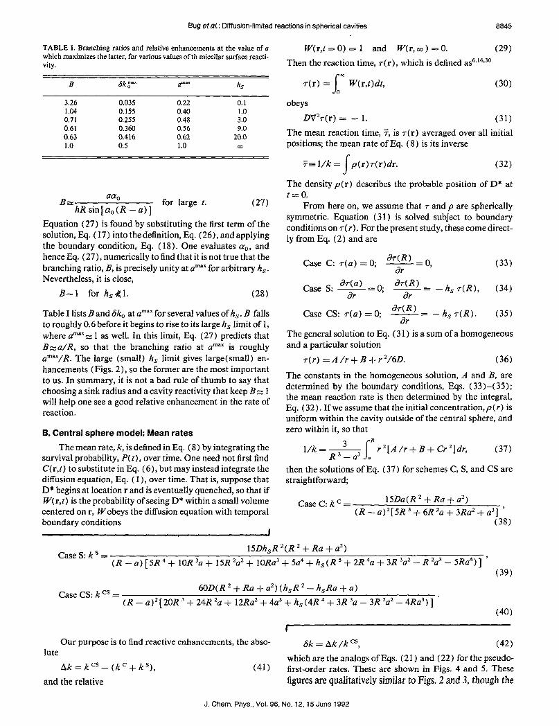
TABLE I. Branching ratios and relative enhancements at the value of a which maximizes the latter, for various values of th micellar surface reacti- vity.
B 6k mar 0 amar hs
3.26 0.035 0.22 0.1 1.04 0.155 0.40 1.0 0.71 0.255 0.48 3.0 0.61 0.360 0.56 9.0 0.63 0.416 0.62 20.0 1.0 0.5 1.0 m
BZ aa
hRsin[a,(R -a)] for large 1. (27)
Equation (27) is found by substituting the first term of the solution, Eq. ( 17) into thedefinition, Eq. (26), and applying the boundary condition, Eq. ( 18). One evaluates cyo, and hence Eq. (27)) numerically to find that it is not true that the branching ratio, R, is precisely unity at amax for arbitrary h,. Nevertheless, it is close,
R-1 for hs&l. (28)
Table I lists B and 6k, at amax for several values of hS . B falls to roughly 0.6 before it begins to rise to its large h, limit of 1, where amax, 1 as well. In this limit, Eq. (27) predicts that B=:a/R, so that the branching ratio at amax is roughly amax/R. The large (small) h, limit gives large(smal1) en- hancements (Figs. 2), so the former are the most important to us. In summary, it is not a bad rule of thumb to say that choosing a sink radius and a cavity reactivity that keep Bz 1 will help one see a good relative enhancement in the rate of reaction.
B. Central sphere model: Mean rates The mean rate, k, is defined in Eq. (8) by integrating the
survival probability, P(t), over time. One need not first find C(r,t) to substitute in Eq. (6), but may instead integrate the diffusion equation, Eq. ( 1 ), over time. That is, suppose that D* begins at location r and is eventually quenched, so that if W( r,t) is the probability of seeing D* within a small volume centered on r, Wobeys the diffusion equation with temporal boundary conditions
W(r,t=O) = 1 and W(r,co) =O. (29) Then the reaction time, r(r), which is defined as6*‘6p30
I
m 7(r) = Wr,t)dt, (30)
0
obeys
DV2r(r) = - 1. (31) The mean reaction time, ;i, is r(r) averaged over all initial positions; the mean rate of Eq. (8) is its inverse
5r l/k = s
p(r)T(r)dr. (32)
The density p(r) describes the probable position of D* at t = 0.
From here on, we assume that r and p are spherically symmetric. Equation (31) is solved subject to boundary conditions on r(r). For the present study, these come direct- ly from Eq. (2) and are
Case C: 7(a) = 0; Jr(R) =o 7’ (33)
Case S: y = 0; Jr(R) - = - h, T(R), ar
(34)
Case CS: T(a) = 0; aT(R) -= -h, T(R). ar
(35)
The general solution to Eq. (3 1) is a sum of a homogeneous and a particular solution
T(r) =A/r+B+r2/6D. (36)
The constants in the homogeneous solution, A and B, are determined by the boundary conditions, Eqs. (33)-(35); the mean reaction rate is then determined by the integral, Eq. (32). If we assume that the initial concentration,p (r) is uniform within the cavity outside of the central sphere, and zero within it, so that
l/k=3 s
R
R3-a3 (I r’[A/r+B+Cr’]dr, (37)
then the solutions of Eq. (37) for schemes C, S, and CS are straightforward;
CaseC:kC= lSDa(R’ + Ra + a*) (R - a)‘[5R 3 + 6R ‘a + 3Ra2 + a31 ’
(38)
Case S: k ’ = lSDh,R 2(R ’ + Ra + a’)
(R - a) [5R 4 + 1OR 3a + 15R ‘a2 + 10Ra3 + 5a4 + h,(R 5 + 2R 4a + 3R 3a2 - R *a3 - 5Ra4)] ’ (39)
Case CS: k cs = 60D(R ’ + Ra -t- a2) (h,R ’ - h,Ra + a)
(R - a)* [ 20R 3 + 24R *a + 12Ra* + 4a3 + h, (4R 4 + 3R 3a - 3R ‘a* - 4Ra3) ] * (40)
Our purpose is to find reactive enhancements, the abso- 6k = Ak /k cs, (42) lute
Ak=kCS-(kC+kS), and the relative
which are the analogs of Eqs. (2 1) and (22) for the pseudo- (41) first-order rates. These are shown in Figs. 4 and 5. These
figures are qualitatively similar to Figs. 2 and 3, though the
J. Chem. Phys., Vol. 96, No. 12,15 June 1992

8848 Bug et&: Diffusion-limited reactions in spherical cavities
k
0 0 2 4 6 6
hs
Ak
- (b) 16- .+=.
16- .=
mm
14- . .=
. .=
12 - . .
2 10 - .
C 6- .=
9
6- =
.= “*..““~“*
4- . A““ . d“
* m A‘ A“‘
2- : “A‘
“A.*
*. A‘ . . . . . . . . . . . . . . . . . . . . . . . . . . . . . . . . . . . . 0*
0 2 4 6 6 IO
hs
,
+,.#-==-
0.3 - Ic” Nm+&-~‘
““““‘*
Sk ‘P ‘A‘ = 1: A“ m= 0.2 - A“ .*
A . .
A‘ = ‘ N
A n
O.l- A: 9
,,.m.mm,.... .9..m-9-9----m-~~- ,...=-
,...... ===
.4- ;
0.0 * . . . . . . . . . . . . . . . . . . . . . . . . . . . ...*.. ,,,,,.. 9. ..,, ,,. I I I 0 2 4 6 6 10
FIG. 4. (a) Mean rate as a function of h,; central sphere has radius a = 0.1. Empty circles: k ’ + k ‘, filled circles: k “. (b) Absolute enhancement of k vs h,. Small triangles: a = 0.01, small squares: a = 0.1, large triangles: a = 0.4, large squares: a = 0.7. (c) Relative enhancement of k vs h,. Sym- bols as in (b).
40
30
k
20
10
0
.*2 .‘oO
l ‘OO .$OO
RYO43@X3Ob@ @8@
0‘
+ 0.t
I I
1 012 014 0.6 0.6
a
0
.
.” b0
00 l O
% l o
6o (b) .
50 -
n A
40 - .
Ak . A
30 - . . . A
. A I
0.0 0.2 0.4 0.6 0.6
a
o.4 (c) 1 NH *m-=4,,
# x mN 9 2 9 . . . . . A‘ “““““‘
n A‘ ‘A .
n A‘ ‘A .
0.2 j = A‘
‘A A
=A A n
A m.
# A ,.-- -------==. A =. A .
.A‘ .- . =.
=. A
DA .- -. ‘ . 0.1 - . '. A
=‘. -9 9‘. -.
A
~~:....--------. . . . . . . . . . l . Am
. -. ‘ . 1’.• ---A--- . . . . . . l ,, ..‘
0.0 * . ~o:o 0:2 0:4 0:6 0:s 1:o
a
FIG. 5. (a) Mean rate as a function of a, for h, = 1. Symbols as in Fig. 4(a). (b) Absolute enhancement of k vs a. Small triangles: h, = 0.1, small squares: h, = 1, large triangles: h, = 3, Iarge squares: h, = 9. (c) Relative enhancement of k vs a. Symbols as in (b) .
J. Chem. Phys., Vol. 98, No. 12,15 June 1992

mean rate, k, exceeds k, for given values of a and h,. One sees competition between sinks [Figs. 4(a) and 5(a) ] and absolute enhancements that grow with h, and a [Figs. 4(b) and 5 (b) 1. One also sees a peak value, Sk max of the relative enhancement [Fig. 5(c) ] at an intermediate sink radius, amax. There is scant quantitative difference between Sk”“” and Sk y for a given h,; the values, urnax, at which these peaks occur are similar as well. In short, the mean and psuedo-first-order rates provide similar evidence of reactive enhancement due to competition between the central sink and micellar surface.
III. APPLICATION TO NMR DETERMINATION OF PORE STRUCTURE
NMR is an important tool in the determination of the structure of porous solids.32 For example, ‘29Xe within the pore spaces of a zeolite may produce a signal with peaks of different strengths centered at different chemical shifts. These strengths give one an estimate of the distribution of pore sizes in the solid.33 As an alternative to looking at chemical shifts, pore structure can be inferred by following the dynamics ofspins within the pores as they evolve in time. The typical time for an initially aligned population of nuclei to disalign due to collisions with the walls is called T,, a spin-lattice relaxation time.
One can write an expression for the time evolution of the magnetization, m(r,r), which models the motion of the nu- clei as diffusive, and assumes that m decays at a fixed rate in the bulk. This decay occurs at a different rate if r is rQ,, a location on the ith region of pore wall. In other words,34s35
am(r,t) - = DV2m(r,t) - k,m(r,t) at (43)
subject to
am(r& an =
- h,,m(r,,t)tft. (4.4)
The analogy to Eqs. ( 1) and (2) is apparent. The bulk relax- ation rate is k,. In this context, it is completely analogous to a spontaneous rate for quenching of D* (see Sec. II A). Thus we set it to zero in Eq. (43). When an experimental rate is predicted, it will just be a sum of k, and the rate determined by the solution to this diffusion equation, subject to the boundary conditions, Eq. (44). In the magnetic sys- tem, the quenching strength h, (Dh, is sometimes called a “killing strength”) depends on the the assumed thickness of the interfacial layer, and details of the atoms involved.
In practical applications, one might measure the total magnetic moment of a sample: M(t) =fm(r,t)dr, and then attempt to model the solid in order to produce a solution of Eq. (43) which fits M(t). The geometry of the pore walls is an important ingredient, and one might pick a generic shape (slit, cylindrical, or spherical pores, * *. ) and then fit other parameters to the data. 36 In order to characterize M( t), one can proceed just as in our original application of diffusion- limited quenching, and extract a pseudo-first-order time, or a mean time, 7. In particular, the mean relaxation time has
been found to be especially significant in porous solid appli- cations. Torquato3’ has shown that there is a rigorous bound which relates the fluid permeability and the porosity to ? in the limit of strong killing: h, = CO. (This is the diffusion- limited regime.) Wilkinson, Johnson, and Schwartz34 have extended ihis bound to finite quenching rates, and have stud- ied 7 analytically and numerically for various pore geome- tries. The notion of reactive enhancement, which occurs when sinks compete for donors may also be applied here, as various pore surfaces compete to relax nuclear spins. This notion is also relevent to spin-spin relaxation. That is, the relaxation rate of N 129Xe atoms within a zeolite pore chamber will be enhanced above N times relaxation rate of one such atom with N- 1 atoms of the more abundant (spinless) isotope, r3’Xe. In Sec. IV, we examine this model in detail.
The notion of reactive enhancement could conceivably increase the difficulty of deducing pore structure from spin- lattice relaxation times, by introducing additional, relevent parameters to the pore model. As an example, consider a slit pore with rough, molecular walls. Suppose that, without al- tering the wall surfaces or the mean separation, we change the registry between the walls by sliding one along the other. If the walls are far from one another, this shift should have no effect on the rate at which the pore relaxes nuclear spins. If the wall separation is decreased, one may begin to see changes in the relaxation time as the registry changes. To determine when walls are “close enough” to see this effect, one need not only consider the length scale of the surface roughness, but also the length scale h a, ‘. The relative im- portance of these two length scales depends on the pore mod- el; clearly, the larger h pi ‘, the more the walls will act as independent quenchers, and the less rates will depend on registry.
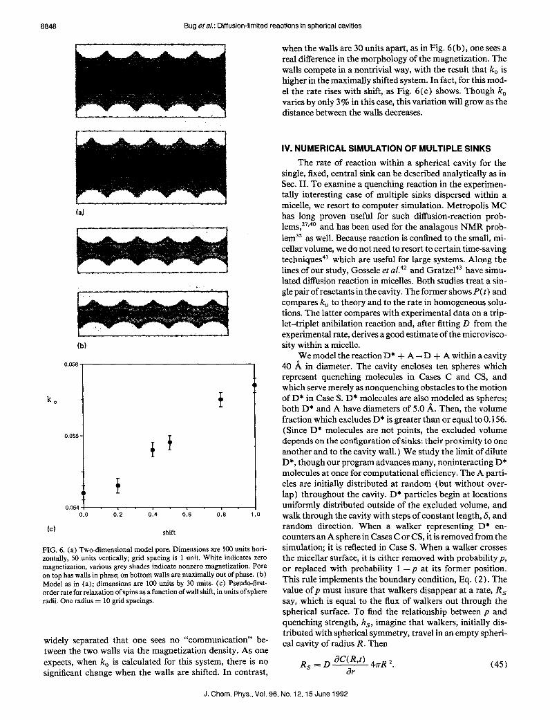
As a numerical example, we have calculated the pseudo- first-order relaxation rate, k,, for a two-dimensional model of this type. The pore, which is shown in Figs. 6(a) and 6(b), has five hemispherical bumps along its inner surface. To avoid edge effects in the computation, the pore is assigned periodic boundary conditions in the horizontal direction. Each hemisphere has a radius of 10 units. In Fig. 6(a), the pore walls (sphere centers) are separated by 50 units; in Fig. 6(b) the separation is decreased to 30 units. We have set h, = co for the pore surfaces-the strong killing limit. To find k, , a square grid with spacing of 1 unit was superposed on the space and a solution to Eq. (43 > was found by a simple finite-element technique. That is, all grid sites within the pore space begin with a fixed magnetization and the solution to the diffusion equation is generated for successive, discrete time steps. So long as the iteration time is very much less than l/D, this method is stable.38 One can find k, either by fitting the long-time decay of M( t) to an exponential, or by using a finite element version of Eq. (25) on m (r,t) at long times; both were done and the results found to be consistent.
The magnetization at a time late in the calculation is shown by the various shadings of grey in the figures.39 In the top image in Fig. 6(a), the walls are in phase; in the bottom, they are shifted to be 180” out of phase. The magnetization varies swiftly near the walls, but the walls are sufficiently
Bug &al.: Diffusion-limited reactions in spherical cavities 8847
J. Chem. Phys., Vol. 96, No. 12,15 June 1992
8848 Bug Hal.: Diffusion-limited reactions in spherical cavities
r
(a)
f
(b)
when the walls are 30 units apart, as in Fig. 6 (b), one sees a real difference in the morphology of the magnetization. The walls compete in a nontrivial way, with the result that k, is higher in the maximally shifted system. In fact, for this mod- el the rate rises with shift, as Fig. 6(c) shows. Though k, varies by only 3% in this case, this variation will grow as the distance between the walls decreases.
IV. NUMERICAL SIMULATION OF MULTIPLE SINKS
The rate of reaction within a spherical cavity for the single, fixed, central sink can be described analytically as in Sec. II. To examine a quenching reaction in the experimen- tally interesting case of multiple sinks dispersed within a micelle, we resort to computer simulation. Metropolis MC has long proven useful for such diffusion-reaction prob- lems,27*40 and has been used for the analagous NMR prob- lem35 as well. Because reaction is confined to the small, mi- cellar volume, we do not need to resort to certain time-saving techniques41 which are useful for large systems. Along the lines of our study, Gossele et aL4’ and Gratze143 have simu- lated diffusion reaction in micelles. Both studies treat a sin- gle pair of reactants in the cavity. The former shows P( t) and compares k, to theory and to the rate in homogeneous solu- tions. The latter compares with experimental data on a trip- let-triplet anihilation reaction and, after fitting D from the experimental rate, derives a good estimate of the microvisco- sity within a micelle.
t
i
T
f
0.054 I I I . I . I
0.0 0.2 0.4 0.6 0.6
Id shit
FIG. 6. (a) Two-dimensional model pore. Dimensions are 100 units hori- zontally, 50 units vertically; grid spacing is 1 unit. White indicates zero magnetization, various grey shades indicate nonzero magnetization. Pore on top has walls in phase; on bottom walls are maximally out of phase. (b) Model as in (a); dimensions are 100 units by 30 units. (c) Pseudo-first- order rate for relaxation of spins as a function of wall shift, in units of sphere radii. One radius = 10 grid spacings.
widely separated that one sees no “communication” be- tween the two walls via the magnetization density. As one expects, when k, is calculated for this system, there is no significant change when the walls are shifted. In contrast,
We model the reaction D* + A -+ D + A within a cavity 40 A in diameter. The cavity encloses ten spheres which represent quenching molecules in Cases C and CS, and which serve merely as nonquenching obstacles to the motion of D* in Case S. D* molecules are also modeled as spheres; both D* and A have diameters of 5.0 A. Then, the volume fraction which excludes D* is greater than or equal to 0.156. (Since D* molecules are not points, the excluded volume depends on the configuration of sinks: their proximity to one another and to the cavity wall.) We study the limit of dilute D*, though our program advances many, noninteracting D* molecules at once for computational efficiency. The A parti- cles are initially distributed at random (but without over- lap) throughout the cavity. D* particles begin at locations uniformly distributed outside of the excluded volume, and walk through the cavity with steps of constant length, S, and random direction. When a walker representing D* en- counters an A sphere in Cases C or CS, it is removed from the simulation; it is reflected in Case S. When a walker crosses the micellar surface, it is either removed with probability p, or replaced with probability 1 -p at its former position. This rule implements the boundary condition, Eq. (2). The value of p must insure that walkers disappear at a rate, R, say, which is equal to the flux of walkers out through the spherical surface. To find the relationship between p and quenching strength, h,, imagine that walkers, initially dis- tributed with spherical symmetry, travel in an empty spheri- cal cavity of radius R. Then
R s
=D saw) 4nR =~ 6% (45)
J. Chem. Phys., Vol. 96, No. 12,15 June 1992
Bug et&: Diffusion-limited reactions in spherical cavities 6849
Now consider the number of walkers, N&t), which are within a step length, 6, of the surface
N( R,t) = C( R,t)4nR *S. (46) With this definition, Eqs. (2) and (45) imply
R,=Dh,N(R,t)/S. (47) Consider the random walk simulation. On a single MC step, the number of walkers that will attempt to cross the wall is fN(R,t). 44 If the time between walker steps is Ar, which is imagined to be small, then
pN(R,t)/4=R,Ar. (48) Using the relationship between a random walk and diffusion in three dimensions: D = S*/6Ar, we arrive at the relation- ship between p and h,
4Rs6* ’ = 6DN(R,t)
= +- h&S. (49)
This relationship was used with success, for h, = 0.5,0.8, to test Eqs. (39) and (40) for the total reaction rate in these analytically solvable cases.
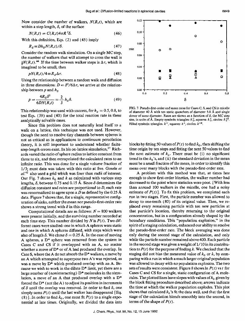
Since this problem does not naturally lend itself to a walk on a lattice, this technique was not used. However, though the need to resolve tiny channels between spheres is not as critical as in applications to continuum percolation theory, it is still important to understand whether finite- step-length errors exist. In his on-lattice simulation,” Rich- ards varied the ratio of sphere radius to lattice constant from three to six, and then extrapolated the calculated rates to an infinite ratio. This was done for a single volume fraction of l/3; most data was taken with this ratio at five. Gosele et aI. also used a grid which was finer than radii of interest. Our Fig. 7 shows k, and k as calculated with various step lengths, S, between 0.75 and 0.15 A. Since 6 determines the diffusion constant and rates are proportional to D, each rate was renormalized to agree upon a D as defined by the 0.25 b; data. Figure 7 shows that, for a single, representative config- uration of sinks, neither the mean nor pseudo-first-order rate shows a strong trend with S in this range.
Computational details are as follows: N = 800 walkers were present initially, and the surviving number recorded at each time step. This number divided by N is P(t). Two dif- ferent cases were studied: one in which A spheres were static and one in which A spheres diffused, with steps which were also of length 6. We chose S = 0.25 A. In the case of moving A spheres, a D* sphere was removed from the system in Cases C and CS if it overlapped with an A, no matter whether a move of D* or of A had produced the overlap. In Case S, where the A do not absorb the D* walkers, a move by an A which attempted to superpose two A’s was rejected, as was a move by D* which produced overlap with an A. Be- cause we wish to work in the dilute D* limit, yet there are a large number of (noninteracting) D* molecules in the simu- lation, a move of an A that produced overlap with a D* forced the D* (not the A) to adjust its position in increments of 6 until the overlap was removed. In order to find k, one simply sums P(t) until the last walker has disappeared [Eq. ( 8) 1. In order to find k, , one must fit P(t) to a single expo- nential at late times. Originally, we divided the data into
0.12 w 0 0 0
0.10 - 0
0.08 0 -
rate 0 0
0.06 -
0.04 -
n I I I
% 0 0.02 - H A n
0.00 - 1 I I 0.0 0.2 0.4 0.6 0.8
6
FIG. 7. Pseudo-first-order and mean rates for Cases C, S, and CS in micelle of diameter 40 A with ten static quenchers of diameter 5.0 b; and single donor of same diameter. Rates are shown as a function of 6, the MC step size, in units of A. Empty symbols: triangles: k ,‘, squares: k it circles: k 0”. Filled symbols: triangles: kc, squares: k s, circles: k a,
blocks by fitting 50 values of P( t) to find k,, then shifting the time origin by ten steps and fitting the next 50 values to find the next estimate of k,. There must be (i) no significant trend in the ko’s, and (ii) the standard deviation in the mean must be a small fraction of the mean, in order to identify this mean over many blocks with the pseudo-first-order rate.
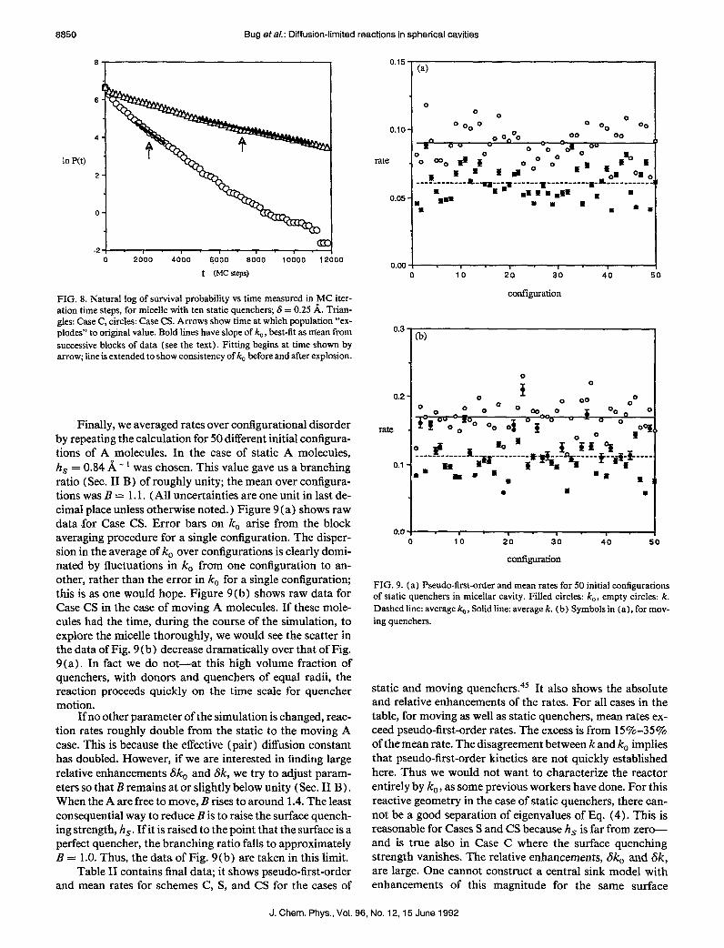
A problem with this method was that, at times late enough to show first-order kinetics, the walker number had decreased to the point where statistics were poor. [With less than around 100 walkers in the micelle, one had a noisy estimate of P( t) 1. To fix this problem, we completed each run in two stages. First, the particle number was allowed to decay to one-tenth (80) of its original value. Then, we re- placed every remaining particle with ten new particles at that particle’s location, thereby returning to the original concentration, but in a configuration already shaped by the boundary conditions. This “population explosion,” in the spirit of a staging calculation, enhanced our ability to resolve the pseudo-first-order rate. The block averaging was done only during the second stage of the calculation, and only while the particle number remained above 400. Each particle in the second stage was given a weight of l/10 in its contribu- tion to P(t) for the purpose of finding k. We checked that the staging did not bias the measured value of k. or k, by com- paring with a run in which a much larger original population was allowed to decay with no population explosion. The two sets of results were consistent. Figure 8 shows In P(t) vs t for Cases C and CS for a single, static configuration of A mole- cules. The plotted lines have slopes with values of k, given by the block fitting procedure described above; arrows indicate the time at which the walker population explodes. This plot shows that calculated k,‘s fit the data well, and that the first stage of the calculation blends smoothly into the second, in terms of the shape of P( t).
J. Chem. Phys., Vol. 96, No. 12,15 June 1992
8850 Bug eta/.: Diffusion-limited reactions in spherical cavities
6
4
In P(t) 2
0
0 2000 4000 6000 6000 10000 12000
t (MCWS)
FIG. 8. Natural log of survival probability vs time measured in ,MC iter- ation time steps, for micelle with ten static quenchers; S = 0.25 A. Trian- gles: Case C, circles: Case CS. Arrows show time at which population “ex- plodes” to original value. Bold lines have slope of kc, best-fit as mean from successive blocks of data (see the text). Fitting begins at time shown by arrow; line is extended to show consistency of k,, before and after explosion.
Finally, we averaged rates over configurational disorder by repeating the calculation for 50 different initial configura- tions of A molecules. In the case of static A molecules, h, = 0.84 A - ’ was chosen. This value gave us a branching ratio (Sec. II B) of roughly unity; the mean over configura- tions was B = 1.1. (All uncertainties are one unit in last de- cimal place unless otherwise noted. ) Figure 9 (a) shows raw data for Case CS. Error bars on k, arise from the block averaging procedure for a single configuration. The disper- sion in the average of k, over configurations is clearly domi- nated by fluctuations in k, from one configuration to an- other, rather than the error in k, for a single configuration; this is as one would hope. Figure 9(b) shows raw data for Case CS in the case of moving A molecules. If these mole- cules had the time, during the course of the simulation, to explore the micelle thoroughly, we would see the scatter in the data of Fig. 9(b) decrease dramatically over that of Fig. 9(a). In fact we do not-at this high volume fraction of quenchers, with donors and quenchers of equal radii, the reaction proceeds quickly on the time scale for quencher motion.
If no other parameter of the simulation is changed, reac- tion rates roughly double from the static to the moving A case. This is because the effective (pair) diffusion constant has doubled. However, if we are interested in finding large relative enhancements Sk,, and 6k, we try to adjust param- eters so that B remains at or slightly below unity (Sec. II B). When the A are free to move, B rises to around 1.4. The least consequential way to reduce B is to raise the surface quench- ing strength, h,. If it is raised to the point that the surface is a perfect quencher, the branching ratio falls to approximately B = 1.0. Thus, the data of Fig. 9(b) are taken in this limit.
Table II contains final data; it shows pseudo-first-order and mean rates for schemes C, S, and CS for the cases of
0.15 (4
0
O 0 0 o. 0 0
0 OO 00
00 00 BY
0 0,“o L 00
0 0 8 O 0 /I
0 0 -0 0
i i ,I” 0
i * I .aoo
0 ,“a *onEsoa’
0 ------------a-,*---r------~----------~n-----------
* a= *
* *** *m m n *ii *
n * m * n * *
0.00 I I I 1 I 0 IO 20 30 40 50
configuration
0.3
0.2
rate
0.1
0.0
(b)
0 J.
q%yo~oo OooO .; .;--,
0 00 0
0 0 0 g Oo ,
” - 0 o” 09
LP ----- .,.-.!.. f i so “i i
s* iH
1. g*
s*$-*4i ---- ~--i~i&-~ a
*a B
. a .
I
0 10 20 30 40
configuration
FIG. 9. (a) Pseudo-first-order and mean rates for 50 initial configurations of static quenchers in micellar cavity. Filled circles: k,, empty circles: k. Dashed line: average &, Solid line: average k. (b) Symbols in (a), for mov- ing quenchers.
static and moving quenchers.4s It also shows the absolute and relative enhancements of the rates. For all cases in the table, for moving as well as static quenchers, mean rates ex- ceed pseudo-first-order rates. The excess is from 15%-35% of the mean rate. The disagreement between k and k, implies that pseudo-first-order kinetics are not quickly established here. Thus we would not want to characterize the reactor entirely by k, , as some previous workers have done. For this reactive geometry in the case of static quenchers, there can- not be a good separation of eigenvalues of Eq. (4). This is reasonable for Cases S and CS because h, is far from zero- and is true also in Case C where the surface quenching strength vanishes. The relative enhancements, Sk, and Sk, are large. One cannot construct a central sink model with enhancements of this magnitude for the same surface
J. Chem. Phys., Vol. 96, No. l&l5 June 1992

Bug eta/.: Diffusion-limited reactions in spherical cavities 8851
TABLE II. Rates, absolute (A rate), and relative (6 rate) enhancements for reaction in a 406; micelle with 10, 5.OA static (h, = 0.84A- ‘) andmoving (h, = CO) quenchers, Ratesarerenormalizedso that Dz l.OA*/ps.
C S cs A Rate 6 Rate
k, k
k, k
Static 0.017 * 0.001 0.0223 10.0004 0.060 f 0.002 0.021 + 0.002 35% 0.026 f 0.001 0.03 19 f o.coo4 0.090 * 0.002 0.032 + 0.002 36%
Moving 0.045 * 0.003 0.034 f 0.001 0.111 f 0.005 0.032 + 0.006 29% 0.056 & 0.002 0.0504 f 0.0005 0.169 f 0.003 0.063 f 0.004 37%
quenching strength. That is, referring back to Figs. 3 (c) and 5(c), there is no radius of central sink which, given h, = 0.84, will produce 35% enhancements as seen for the static data in Table II. To summarize a main point: One cannot view reactions at the surface and within this micelle as occuring in parallel. Any analysis of such a system which begins with the assumed superposition of rates, kc+ks= k cs, will begin with an error which propagates through the calculation. For the (physically motivated) pa- rameters we have studied, this initial error is roughly 35%.
In conclusion, we have studied the absolute and relative enhancement in reaction rate that is achieved by placing quenchers both within and on the surface of a micellar cav- ity. We have found significant enhancement both in the case of a single, central quencher, and for dispersed static and moving quenchers in a micelle-enhancements not too far below a conjectured maximum of 50%. These results imply that, in general, one cannot view reaction at the surface and within the micellar volume as channels which operate in par- allel, save in the limit of weak quenching and small quencher radius. On a more positive note, the results suggest a way to enhance the efficiency of a diffusion-limited reaction within a micelle or porous solid. One attempts to distribute reagent or catalyst simultaneously on surfaces which are expected to compete; just as surfaces within the pore and at the pore surface compete in the present study. Finally, we have noted that these results apply to the relaxation of magnetization as seen through NMR measurements, and have studied a type of competition between relaxing surfaces in a simple model of a pore with rough walls.
We thank J. Boccio, P. Collings, R. Dumont, D. John- son, and J. Talvaccia for helpful discussions. We are also grateful for computing support from M. Wall and the Aca- demic Computing Center, and we gratefully acknowledge financial support from the Division of Natural Sciences, the Faculty Research Support Fund, and the Provost’s office at Swarthmore College. Acknowledgment is made to the do- nors of the Petroleum Research Fund, administered by the American Chemical Society, for support of this research un- der Grant No. 19890-AC6. Finally, we gratefully acknowl- edge grant support of computer time on a CRAY Y-MP from the Academic Affiliates Program at the National Cen- ter for Supercomputing Applications at the University of Illinois, Urbana-Champaign.
’ G. Adam and M. Delbruck, in Structural Chemistry and Molecular Bio- Iogy, edited by A. Rich and N. Davidson (Freeman, San Francisco, 1968).
2M. D. Hatlee, J. J. Kozak, G. Rothenberger, P. P. Infelta, and M. Gratzel, J. Phys. Chem. 84, 1508 ( 1980).
‘A. J. Frank, M. Grazel, and J. J. Kozak, J. Am. Chem. Sot. 98, 3317 ( 1976); J. H. Fendler, Act. Chem. Res. 13,7 ( 1980); J. H. Fendler and E. J. Fendler, Catalysis in Micellar and Macromolecular Systems (Aca- demic, New York, 1985).
41. R. Gould, M. B. Zimmt, N. J. Turro, B. H. Baretz, and G. F. Lehr, J. Am. Chem. Sot. 107,4607 ( 1985); N. J. Turro, M. B. Zimmt, X. G. Lei, I. R. Gould, K. S. Nitsche, and Y. Cha, J. Phys. Chem. 91,4544 ( 1987).
’ K. Kalyanasundaram, Photochemistry in Microheterogeneous Systems (Academic, New York, 1987).
6M. Tachiya, in Kinetics of Nonhomogeneous Processes, edited by G. R. Freeman (Wiley, New York, 1987).
‘J. R. Escabi-Perez, A. Romero, S. Lukac, and J. H. Fendler, J. Am. Chem. Sot. 101,223 1 ( 1979); Y. Moroi, A. M. Braun, and M. Gratzel, ibid. 101, 567 (1979).
*T. Nomura, J. R. Escabi-Perez, J. Sunamoto, and J. H. Fendler, J. Am. Chem. Sot. 102, 1484 (1980).
9V. Ramesh and M. M. Labes, J. Am. Chem. Sot. 108,4643 ( 1986); V. Ramesh and M. M. Labes, Mol. Cryst. Liq. Cryst. 144,257 ( 1987).
“M. Almgren, J. Alsins, E. Mukhtar, and J. van Stam, J. Phys. Chem. 92, 4479 (1988).
‘I R. Ark, The Mathematical Theory of Dtyision and Reaction in Perme- ah/e Catalysis, Vols. I and II (Clarendon, Oxford, 1975).
‘*R. Samson and J. M. Deutch, J. Chem. Phys. 68,285 ( 1978). I3 M. Van der Auweraer, J. C. Dederen, E. Gelade, and F. C. De Schryver, J.
Chem. Phys. 74, 1142 ( 198 1). I4 See the “ink-bottle” pore model of Chu and Chon in Chap. 3 of Ref. 11. “H. S. Carslaw and J. C. Jaeger, Conduction of Heat in Solids (Oxford
University, London, 1959); E. F. Casassa and Y. Tagami, Macromole- cules 2, 14 ( 1969); M. Tachiya, Chem. Phys. Lett. 69, 605 ( 1980).
16H. Sano and M. Tachiya, J. Chem. Phys. 75,287O (1981). “P. P. Infelta, M. Gretzel, and J. K. Thomas, J. Phys. Chem. 78, 190
( 1974); J. C. Dederen, M. Van der Auweraer, and F. C. De Schryver, Chem. Phys. Lett. 68,45 1 (1979); P. P. Infelta and M. Gratzel, J. Chem. Phys. 70, 179 (1979).
‘*M. Tachiya, Chem. Phys. Lett. 33,289 ( 1975); P. P. Infelta and M. Grat- zel, J. Chem. Phys. 78,528O (1983); M. Tachiya, ibid. 78, 5282 (1983).
19M. D. Hatlee and J. J. Kozak, J. Chem. Phys. 72,4358 ( 1980). “For a review, see G. H. Weiss, J. Stat. Phys. 42,3 (1986); more recently,
K. Mattern and B. U. Felderhof, Physica A 143, 1 ( 1987); J. Rubinstein and S. Torquato, J. Chem. Phys. 88,6372 ( 1988); M. Lowenberg and G. R. Gavalas, J. Chem. Phys. 90, 177 ( 1989).
21 C. W. J. Beenakker and J. Ross, J. Chem. Phys. 84,3857 ( 1986); K. Mat- tern and B. U. Felderhof, ibid. 85, 5382 (1986); also see Ref. 27.
‘*M. Smoluchowski, Phys. Z. 17, 557 (1916). 23P. M. Richards, J. Chem. Phys. 85,352O (1986). 24R. I. Cukier, J. Stat. Phys. 42, 69 ( 1986). 2sA. Stem and M. Volmer, Phys. Z. 20, 183 (1919). ” G. Artken, Mathematical Methods for Physicists (Academic, New York,
1985). 27P. M. Richards, Phys. Rev. B 35,248 ( 1987).
J. Chem. Phys., Vol. 96, No. 12,15 June 1992

8852 Bug et a/.: Diffusion-limited reactions in spherical cavities
‘*U. Gosele and A. Seeger, Philos. Mag. 34, 177 ( 1976). 29 G. H. Weiss, Adv. Chem. Phys. 13, 1 (1967). =A. Szabo, K. Schulten, and 2. Schulten, J. Chem. Phys. 72,435O ( 1980). 3’ J. Rauch, in Lecture Notes in Mathematics, 446, edited by .I. A. Goldstein
(Springer, Berlin, 1975). 3zW. E. Kenyon, P. Day, C. Straley, and J. Willemsen, paper SPE-15643,
presented at 61st Annual Technical Conference of Society of Petroleum Engineers, New Orleans, 1986; C. Straley, A. Matteson, S. Feng, L. M. Schwartz, W. E. Kenyon, and J. R. Banavar, Appl. Phys. L&t. 51, 1146 (1987); J. Fraissard and T. Ito, Zeolites 8, 350 (1988).
“J. A. Ripmeester and D. W. Davidson, 3. Mol. Struct. 75, 67 (1981). “D. J. Wilkinson, D. L. Johnson, and L. M. Schwartz, Phys. Rev. B 44 II,
4960 (1991). “J. R. Banavar and L. M. Schwartz, Phys. Rev. Lett. 58, 1411 (1987). 36K. R. Brownstein and C. E. Tarr, Phys. Rev. A 19,2446 ( 1979). 37S. Torquato, Phys. Rev. Lett. 64, 2644 (1990). 38C R. Wylie and L. C. Barrett, Advanced Engineering Mathematics
(McGraw-Hill, New York, 1982), Chap. 5. 39 Figure 6 uses a “high frequency” palette, in which the darkness of grey
shading tends to increase as density increases, but with an oscillatory character.
“‘M. Dumont, J. Ravez, and P. M. Petropoulos, in ProceedingsofZnd Euro- pean Simulation Congress, edited by G. C. Vansteenkiste (Antwerp, 1986).
” L. H. Zheng and Y. C. Chiew, J. Chem. Phys. 90,322 (1989). ‘* U. Gosele, U. K. A. Klein, and M. Hauser, Chem. Phys. Lett. 68, 29 1
(1979). 43 M. Gratzel, Tetrahedron 43, 1679 (1987). u We assume that 6 is sufficiently small so that (i) The curvature of the
shell of width Scan be neglected on the scale of the walker’s motion: S (R; (ii) The concentration is roughly uniform in the shell. With these two assumptions, one calculates the likelihood that a walker a distance z<6 from the wall crosses it on the next step, and then averages over all z between 0 and S, to find a factor of l/4.
“‘Since there is no time interval associated, a priori, with one MC iteration time, we can assign Ar a value (of 0.010 ps) so that for 6 = .25 A, parti- cles move as if they were diffusing in three dimensions with D = 1.0 A’/ps. The reported values in Table II reflect this choice.
J. Chem. Phys., Vol. 98, No. 12,15 June 1992