digidesign and rm2akmedia.digidesign.com/support/docs/rm1_rm2_guide_37859.pdf · nel assignment †...
TRANSCRIPT

Digidesign® RM1™ and RM2™
Professional Reference Monitors

Copyright
© 2008 Digidesign, a division of Avid Technology, Inc. All rights reserved.
Product features, specifications, system requirements, and availability are subject to change without notice.
This guide may not be duplicated in whole or in part without the express written consent of Digidesign. Avid, Digidesign, Pro Tools, RM1 and RM2 are either trademarks of Avid Technology, Inc. in the US and/or other countries. All other trademarks contained herein are the property or their respective owners.
THIRD PRINTING 01/08

Communications & Safety Regulation Information
Compliance StatementThe models RM1 and RM2 comply with the following standards regulating interference and EMC:• FCC Part 15 Class B• EN55103-1 E1• EN55103-2 E1• AS/NZS 3548 Class B• CISPR 22 Class B
Radio and Television InterferenceThis equipment has been tested and found to comply with the limits for a Class B digital device, pursuant to Part 15 of the FCC Rules.
DECLARATION OF CONFORMITY
We, Digidesign, 2001 Junipero Serra Boulevard
Daly City, CA 94014-3886, USA
650-731-6300
declare under our sole responsibility that the products
RM1 and RM2
comply with Part 15 of FCC Rules.
Operation is subject to the following two conditions: (1) this device may not cause harmful interference, and (2) this device must accept any interference received, including interference that may cause undesired operation.
Communication Statement
NOTE: This equipment has been tested and found to comply with the limits for a Class B digital device, pursuant to Part 15 of the FCC Rules. These limits are designed to provide reasonable protection against harmful interference in a residential installation. This equipment generates, uses, and can radiate radio frequency energy and, if not installed and used in accordance with the instructions, may cause harmful interference to radio communications. However, there is no guarantee that interference will not occur in a particular installation. If this equipment does cause harmful interference to radio or television reception, which can be determined by turning the equipment off and on, the user is encouraged to try and correct the interference by one or more of the following measures:• Reorient or locate the receiving antenna.• Increase the separation between the equipment and
receiver.• Connect the equipment into an outlet on a circuit different
from that to which the receiver is connected.• Consult the dealer or an experienced radio/TV technician
for help.
Any modifications to the unit, unless expressly approved by Digidesign, could void the user's authority to operate the equipment.
Canadian Compliance Statement:
This Class B digital apparatus complies with Canadian ICES-003
Cet appareil numérique de la classe B est conforme à la norme NMB-003 du Canada
Australian Compliance

CE Compliance Statement:
Digidesign is authorized to apply the CE (Conformité Europénne) mark on this compliant equipment thereby declaring conformity to EMC Directive 89/336/EEC and Low Voltage Directive 73/23/EEC.
Safety StatementThis equipment has been tested to comply with USA and Canadian safety certification in accordance with the specifications of UL Standards: UL60065 7th /IEC 60065 7th and Canadian CAN/CSA C22.2 60065:03. Digidesign Inc., has been authorized to apply the appropriate UL & CUL mark on its compliant equipment.
Warning
Important Safety Instructions
1) Read these instructions.
2) Keep these instructions.
3) Heed all warnings.
4) Follow all instructions.
5) Do not use this apparatus near water.
6) Clean only with dry cloth.
7) Do not block any ventilation openings. Install in accordance with the manufacturer’s instructions.
8) Do not install near any heat sources such as radiators, heat registers, stoves, or other apparatus (including amplifiers) that produce heat.
9) Do not defeat the safety purpose of the polarized or grounding-type plug. A polarized plug has two blades with one wider than the other. A grounding type plug has two blades and a third grounding prong. The wide blade or the third prong are provided for your safety. If the provided plug does not fit into your outlet, consult an electrician for replacement of the obsolete outlet.
10) Protect the power cord from being walked on or pinched particularly at plugs, convenience receptacles, and the point where they exit from the apparatus.
11) Only use attachments/accessories specified by the manufacturer.
12) Unplug this apparatus during lightning storms or when unused for long periods of time.
13) Refer all servicing to qualified service personnel. Servicing is required when the apparatus has been damaged in any way, such as power-supply cord or plug is damaged, liquid has been spilled or objects have fallen into the apparatus, the apparatus has been exposed to rain or moisture, does not operate normally, or has been dropped.
14) The apparatus shall not be exposed to dripping or splashing and no objects filled with liquids (such as vases) shall be placed on the apparatus.
Warning! To reduce the risk of fire or electric shock, do not expose this apparatus to rain or moisture.
15) The apparatus should be connected to a properly-grounded (earthed) receptacle.
16) The main power switch is located on the back panel of the RM1 and RM2. The mains cord is used as the mains disconnect device and should remain accessible after installation.

contents
Chapter 1. Introduction . . . . . . . . . . . . . . . . . . . . . . . . . . . . . . . . . . . . . . . . . . . . . . . . . . . . . . 1
What’s in the Box? . . . . . . . . . . . . . . . . . . . . . . . . . . . . . . . . . . . . . . . . . . . . . . . . . . . . . . . 1
Features. . . . . . . . . . . . . . . . . . . . . . . . . . . . . . . . . . . . . . . . . . . . . . . . . . . . . . . . . . . . . . . 1
Digidesign Registration . . . . . . . . . . . . . . . . . . . . . . . . . . . . . . . . . . . . . . . . . . . . . . . . . . . . 2
About www.digidesign.com . . . . . . . . . . . . . . . . . . . . . . . . . . . . . . . . . . . . . . . . . . . . . . . . . 2
About the Speakers . . . . . . . . . . . . . . . . . . . . . . . . . . . . . . . . . . . . . . . . . . . . . . . . . . . . . . . 3
Chapter 2. Overview of the RM1 and RM2 . . . . . . . . . . . . . . . . . . . . . . . . . . . . . . . . . . . . . 5
Connectors and Controls . . . . . . . . . . . . . . . . . . . . . . . . . . . . . . . . . . . . . . . . . . . . . . . . . . . 5
Front Panel LED . . . . . . . . . . . . . . . . . . . . . . . . . . . . . . . . . . . . . . . . . . . . . . . . . . . . . . . . . 8
Chapter 3. Setup and Operation . . . . . . . . . . . . . . . . . . . . . . . . . . . . . . . . . . . . . . . . . . . . . . . 9
Getting Started . . . . . . . . . . . . . . . . . . . . . . . . . . . . . . . . . . . . . . . . . . . . . . . . . . . . . . . . . . 9
Setting Up the Speakers . . . . . . . . . . . . . . . . . . . . . . . . . . . . . . . . . . . . . . . . . . . . . . . . . . . 9
Configuring and Connecting AC Power. . . . . . . . . . . . . . . . . . . . . . . . . . . . . . . . . . . . . . . . . 10
Connecting Audio . . . . . . . . . . . . . . . . . . . . . . . . . . . . . . . . . . . . . . . . . . . . . . . . . . . . . . . 11
Power Up and Power Down . . . . . . . . . . . . . . . . . . . . . . . . . . . . . . . . . . . . . . . . . . . . . . . . 13
Configuring Monitor Settings . . . . . . . . . . . . . . . . . . . . . . . . . . . . . . . . . . . . . . . . . . . . . . . 13
Tips for Best Performance . . . . . . . . . . . . . . . . . . . . . . . . . . . . . . . . . . . . . . . . . . . . . . . . . 15
Troubleshooting . . . . . . . . . . . . . . . . . . . . . . . . . . . . . . . . . . . . . . . . . . . . . . . . . . . . . . . . 15
Appendix A. Specifications . . . . . . . . . . . . . . . . . . . . . . . . . . . . . . . . . . . . . . . . . . . . . . . . . . 17
Audio Specifications for the Digidesign RM1 and RM2 . . . . . . . . . . . . . . . . . . . . . . . . . . . . . 17
Power Amplifier Specifications . . . . . . . . . . . . . . . . . . . . . . . . . . . . . . . . . . . . . . . . . . . . . . 19
Reference Diagrams . . . . . . . . . . . . . . . . . . . . . . . . . . . . . . . . . . . . . . . . . . . . . . . . . . . . . 20
Contents v

vi
Digidesign RM1 and RM2 Guide
chapter 1
Introduction
Thank you for choosing Digidesign® Reference Monitor Series (RMS) active reference monitors.
These monitors were engineered by Digidesign with PMC using Advanced Transmission Line Technology.
This guide provides installation and operation instructions for the Digidesign RM1™ and RM2™ speakers.
What’s in the Box? • One RM1 or RM2 monitor
• One AC power cable
• One RJ45 cable
• Digidesign Registration Information Card
For an introduction to the technology and designs at work in Digidesign RMS speakers, see “About the Speakers” on page 3.
RM1
Features The following features are provided on both RM1 and RM2 monitors:
• Active, bi-amped near field monitors
• Digital and analog inputs
• Proprietary drivers, digital electronics, power amp and cabinet engineering provide unri-valled tonal accuracy, clarity and dynamic range with exceptionally low distortion
• Onboard DSP:
• Manages the digital crossover, for clearer imaging
• Provides gain trim (sensitivity), low- and high-frequency adjustment and L/R chan-nel assignment
• Provides Bass Port Emulation, an alternate listening mode in which the RMS speakers emulate the tonality of a ported bass reflex speaker
• Sound dispersion design maintains accurate frequency response even when listening in off-axis position
Chapter 1: Introduction 1

2
Digidesign RegistrationReview the enclosed Registration Information Card and follow the instructions on it to quickly register your purchase online. Registering your purchase is the only way you can be eligible to receive complimentary technical support and future upgrade offers. It is one of the most im-portant steps you can take as a new user.
Contact your local Digidesign dealer for assis-tance, and for information on warranty and re-pair.
Digidesign RM1 and RM2 Guide
About www.digidesign.comThe Digidesign website (www.digidesign.com) is your best source for information to help you get the most out of your Digidesign products. The following are just a few of the services and fea-tures available.
Product Registration Register your purchase on-line. See the Digidesign Registration Informa-tion Card included with your system for instruc-tions.
Support and Downloads Contact Digidesign Technical Support or Customer Service; down-load software updates and the latest online manuals; browse the Compatibility documents for system requirements; search the online An-swerbase or join the worldwide Pro Tools com-munity on the Digidesign User Conference.
Training and Education Study on your own using courses available online or find out how you can learn in a classroom setting at a certified Pro Tools training center.
Products and Developers Learn about Digidesign products; download demo software or learn about our Development Partners and their plug-ins, applications, and hardware.
News and Events Get the latest news from Digidesign or sign up for a Pro Tools demo.

About the SpeakersThe Digidesign RM1 and RM2 are both two-way (bi-amped) active reference monitors with inno-vations in amplifier and crossover design and include PMC’s ATL™ (Advanced Transmission Line) technology.
ATL Technology by PMC
PMC has taken loudspeaker design to the high-est level with the use of ATL (Advanced Trans-mission Line). These designs utilize sophisti-cated cabinets, proprietary drive units and special absorption materials.
How ATL Works
The main driver is placed at one end of a long tunnel (the transmission line), which is com-prised of a series of internal baffles within the cabinet. The transmission line is lined with acoustic material that is designed to absorb the upper bass range that radiates from the rear of the main driver.
The lowest frequencies emerge from the large vent at the end of the tunnel, in phase with the main driver, extending its LF output. The pres-sure created within the line controls the main driver over a wide frequency range, dramatically reducing unnecessary excursions and the result-ing distortion.
The mid range in turn appears cleaner and clearer as it is not masked by harmonic distor-tion residing in the very low frequencies. This technology produces a higher SPL and lower bass extension than a ported or sealed cabinet of a similar size using identical drivers.
Drivers
The RM1 features a 5 and 1/2-inch LF driver, while the RM2 provides a 6.7-inch LF driver. These LF drive units are optimized for an ATL design.
Both the RM1 and RM2 monitors use an identi-cal 1-inch, soft dome, ferro-fluid cooled HF driver.
Amplifier
In the RM series both HF and LF drive units are independently driven by separate low-distor-tion, analog-controlled “Class D” power ampli-fiers. This type of amplifier combines the effi-ciency and size advantages of a digital amplifier with the precision, control and sound quality of linear amplification.
DSP and Crossover
Within the RM series, the crossover function is handled by a digital 48-bit fixed-point proces-sor. The powerful DSP processing engine han-dles the audio signal in the digital domain for precise control and integration of the drive units along with the EQ parameters, Bass Port emulation and Left/Right channel selection.
Clock
The analog input ADC (Analog-to-Digital Con-verter) is sampled at 96 kHz, 24 bits and is locked with a discrete low-noise clock oscillator.
Chapter 1: Introduction 3

4
Digidesign RM1 and RM2 Guide
chapter 2
Overview of the RM1 and RM2
This chapter describes the connectors and controls on the RM1 and RM2 reference monitors.
Connectors and Controls
Figure 1. Back panel of the RM1 (same as RM2)
Voltage selector
Power
Channel AssignGain Trim
LFHF
Controls and
Anchors for optional mount
ACPower switch
Fuse
Inputs
SettingsBass Port Emulation
Analog In AES3 Digital In
INTHRU
Chapter 2: Overview of the RM1 and RM2 5

6
Power
Voltage Selector
Before connecting the speaker to a power sup-ply, ensure the voltage selector setting matches your local main voltage supply (100–115V or 230V), +10% or –15%.
Fuse
The fuse protects your speakers and other com-ponents of the RMS speakers from being dam-aged by electrical under or over-powering, spikes, and other anomalies. Do not use fuses of any other rating except the ones indicated on the back panel of the unit.
Fuses and Voltage
You must use different fuses for the 100–115V and 230V setting. The 100–115V setting uses the 3.15A fuse, and the 230V setting uses the 1.6A fuse. If you change the setting to 230V, you must also change to a 1.6A fuse.
To change fuses:
1 Use a small screw driver to remove the fuse holder.
2 Remove the factory-installed fuse.
Voltage selector
Always make sure to install the proper fuse after changing voltage settings. See below.
Digidesign RM1 and RM2 Guide
3 Install the new fuse in the fuse holder so that it goes in first.
Power Switch and AC Connector
The AC port accepts an AC power cord included with your monitor. Once connected, use the Power switch to turn the unit on or off. To com-pletely isolate the mains, remove the power cord.
Inputs
Analog
The analog audio input is a female XLR connec-tor. The input is electronically balanced with the following connections.
If the source signal is unbalanced, connect the unused pin to ground. For optimum results, use only quality cable and connectors.
Power switch, fuse cover and AC connector
Analog In connector (XLR) showing pin numbering
Power
Fuse AC
switch
Pin 1 GND Pin 2 +Pin 3 –

Digital
The RM series monitors provide an AES 3 digital input (XLR), as well as THRU and IN connectors (RJ45).
AES 3 Digital In
The AES 3 digital audio input is a female XLR connector. The AES 3 input accepts sample rates of 44.1 kHz, 48 kHz, 88.2 kHz, and 96 kHz.
IN
This female RJ45 socket is for connecting AES digital audio from an RJ45 source device, or from the THRU connector on your other, pri-mary RM series monitor.
THRU
This female RJ45 socket provides AES digital au-dio THRU from either the IN RJ45 or AES 3 XLR digital input.
Digital AES In connector (XLR) showing pin numbering
Digital in connector (RJ45) showing pin orientation
Digital Thru connector (RJ45) showing pin orientation
Pin 1 GND Pin 2 +Pin 3 –
Controls and Settings
Each Digidesign RMS speaker provides the fol-lowing back panel controls and settings.
HF Sets an adjustable high frequency level utiliz-ing the built-in HF (shelf-type) EQ. The range of adjustment is –4 dB to +3 dB in 0.5 dB steps.(See “Setting HF” on page 14.)
LF Sets an adjustable low frequency level utiliz-ing built-in LF (shelf-type) EQ. The range of ad-justment is –4 dB to +3 dB in 0.5 dB steps. (See “Setting LF” on page 14.)
Channel Assign Selects which of the channels of the AES digital input (left or right) is repro-duced. (See “Connecting Digital Input” on page 11.)
Gain Trim Sets the input sensitivity. (See “Setting Gain Trim” on page 13.)
Bass Port Emulation
The RM speakers are equipped with the ability to emulate the frequency response of a bass re-flex ported speaker. Although the ATL design provides a more accurate bass response with less distortion, the Bass Port Emulation feature pro-vides the ability to hear how a mix “translates” to a ported speaker. (See “Using Bass Port Emu-lation” on page 15.)
Anchors for Wall Bracket
The four M6 threaded inserts are for use with the proprietary RM1 and M2 tilt and swivel wall bracket (not included). Refer to the Digidesign website (www.digidesign.com) for more infor-mation.
Chapter 2: Overview of the RM1 and RM2 7

8
Front Panel LED This LED indicator appears on the front of both RM1 and RM2 and indicates the following states:
Front Panel LED States
LED Status Indication
UNLIT No power or momentary power up mute mode
BLUE Power on
RED Amplifier clipping – Reduce input level when RED is displayed
Digidesign RM1 and RM2 Guide
chapter 3
Setup and Operation
This chapter provides instructions to connect, configure, and use the Digidesign RM1 and RM2 Reference Monitors.
Correct placement and connection ensures opti-mal performance and safe operation of your monitors.
Getting Started
Unpacking the Monitors
After opening the box, be sure to reach down the sides of the monitor to lift it out of its box. This protects the HF and LF drivers (on the front) from being dented or punctured by your fingers, and prevents any possible damage to the switches, connectors, and other controls on the back of each monitor.
Reuse and Recycling
Please retain your packaging for future use. The cartons are durable, reusable and can be em-ployed to safely transport your loudspeakers should they need to be relocated.
Setting Up the SpeakersReference monitors should always be placed to provide balanced, accurate sound in your pre-ferred mixing position. The exact location de-pends on the size and acoustics of the environ-ment where the speakers are being used. In all installation, observe the following guidelines:
• Place the speakers so they are at the same height as your ears.
• Place the monitors on quality stands, or mount them on a wall using the proper brackets.
• DO NOT soffit mount or otherwise enclose the monitors; they require free air flow around the back panel.
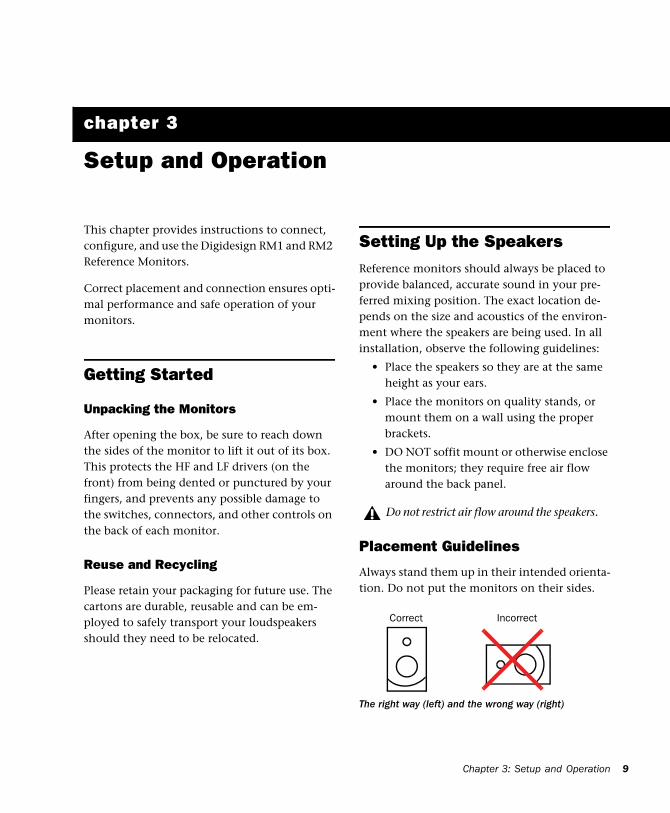
Placement Guidelines
Always stand them up in their intended orienta-tion. Do not put the monitors on their sides.
Do not restrict air flow around the speakers.
The right way (left) and the wrong way (right)
Correct Incorrect
Chapter 3: Setup and Operation 9

10
Vertical placement provides the largest listening window where frequency response and imaging are stable and consistent. Vertical orientation minimizes the effects of driver interaction around the crossover point.
Positioning
Always ensure symmetrical placement of the monitors in relation to the listening position.
Stereo
The following diagram shows the recommended setup for stereo monitoring.
Surround Positioning
The following diagram shows the recommended setup for use in a 5.0 environment.
Stereo placement
Placement of RMS speakers for a 5.0 installation (sub shown for example only)
0.5m/20"
FRONT LEFT FRONT RIGHT
CENTRE
TV ORPLASMA SUBWOOFER
WITHINTHISWINDOW
30o30o25o
100o
135o
25o
REAR RIGHTREAR LEFT
Digidesign RM1 and RM2 Guide
The RM series monitors provide adjustable gain, as well as low-frequency and high-frequency re-sponse controls. These let you optimize the re-sponse of your RM speakers for your listening environment.
Configuring and Connecting AC PowerBe sure to follow the instructions in this section for the proper configuration of fuses and volt-age.
Setting the VoltageMake sure the Voltage Selector setting on both
monitors matches your local main voltage sup-ply (100–115V or 230V).
Installing the Correct Fuse
Make sure you have installed the fuse appro-priate for your area and voltage.
PMC speakers must be manually configured for the voltage in your area. Always check the Voltage setting and fuse, described be-low, before connecting and powering your monitors.
Voltage selector

Do not use fuses of any other rating except the ones indicated on the back panel of the unit.
Connecting AC
To connect power to the monitors:
1 Make sure you have set the Voltage Selector and installed the proper fuse before proceeding. (See “Setting the Voltage” on page 10 for de-tails.)
2 Connect the included AC power cord to the AC connector on the back panel of each moni-tor (one cable is included in each box).
3 Connect the other end to your power source.
Connecting AudioThis section explains how to make analog and digital audio connections to the RM1 and RM2 monitors.
Connecting Analog Input
To connect an analog source:
1 Connect a balanced XLR cable to the Analog In connector on the back panel of the monitor.
Power switch, fuse cover and AC connector
If you need to connect an unbalanced ana-log source, see “Analog” on page 6.
Fuse
2 Connect the other end to the analog audio source (for example, an analog output from a Digidesign 192 I/O audio interface).
3 Repeat steps 1 and 2 for other RM monitors.
Connecting Digital Input
The Digidesign RMS monitors accept AES input from the AES 3 Digital Input (XLR connector) and the IN port (RJ45). RMS monitors clock to the digital source.
About Digital Thru
AES 3 and RJ45 digital protocols carry two chan-nels of audio (left and right). When using a dig-ital source, that source device connects to a dig-ital input on a single RMS monitor. It does not matter which of the two you use as the primary monitor.
The THRU port on this primary monitor is then connected to the IN port on the other “slave” monitor (using the included RJ45 cable) to sup-ply it with its digital audio input.
You then use the Channel Assign switch to as-sign the Left or Right channel of the AES signal to the speaker.
In and Thru connections for digital input (AES source shown)
AES
THRUIN
(from source)RJ45
(Left)
Channel
(Right)Assign
Channel Assign
Chapter 3: Setup and Operation 11
12
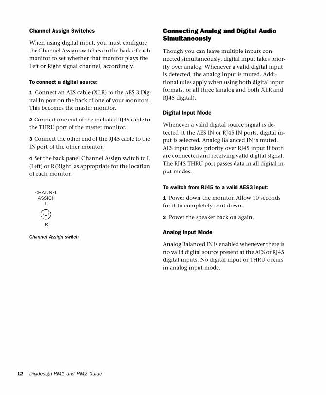
Channel Assign Switches
When using digital input, you must configure the Channel Assign switches on the back of each monitor to set whether that monitor plays the Left or Right signal channel, accordingly.
To connect a digital source:
1 Connect an AES cable (XLR) to the AES 3 Dig-ital In port on the back of one of your monitors. This becomes the master monitor.
2 Connect one end of the included RJ45 cable to the THRU port of the master monitor.
3 Connect the other end of the RJ45 cable to the IN port of the other monitor.
4 Set the back panel Channel Assign switch to L (Left) or R (Right) as appropriate for the location of each monitor.
Channel Assign switch
Digidesign RM1 and RM2 Guide
Connecting Analog and Digital Audio Simultaneously
Though you can leave multiple inputs con-nected simultaneously, digital input takes prior-ity over analog. Whenever a valid digital input is detected, the analog input is muted. Addi-tional rules apply when using both digital input formats, or all three (analog and both XLR and RJ45 digital).
Digital Input Mode
Whenever a valid digital source signal is de-tected at the AES IN or RJ45 IN ports, digital in-put is selected. Analog Balanced IN is muted. AES input takes priority over RJ45 input if both are connected and receiving valid digital signal. The RJ45 THRU port passes data in all digital in-put modes.
To switch from RJ45 to a valid AES3 input:
1 Power down the monitor. Allow 10 seconds for it to completely shut down.
2 Power the speaker back on again.
Analog Input Mode
Analog Balanced IN is enabled whenever there is no valid digital source present at the AES or RJ45 digital inputs. No digital input or THRU occurs in analog input mode.

Power Up and Power DownAlways power up your monitor system last (al-lowing mixers, recorders and other devices to fully power up first).
Conversely, always mute (or power off) your monitor system first, before powering off other devices in your studio.
Initial Use and the “Break In” Period
Many mechanical devices with high tolerance components will take a short time of use to achieve their best performance. This especially applies to the soft pliable surrounds (cones) of both LF and HF drive units of the RMS speakers.
As this material flexes during continued opera-tion, it will gradually attain the perfect compli-ance allowing the units to react faster and with more sensitivity to every nuance of the audio spectrum. The depth and dynamics of bass will improve along with the clarity of image place-ment. The duration of Running/Breaking-in can take up to 14 hours of reasonable use.
Configuring Monitor Settings
Setting Gain Trim
Gain Trim is a 16-position continuous rotary en-coder that lets you match the input sensitivity of the RM1 or RM2 monitor to the source.
The point of maximum sensitivity is when the pointer is straight down (in the 6 o’clock posi-tion). Rotating clockwise from this point de-creases the sensitivity in 1 dB steps to –15 dB.
The Gain Trim encoder has a small opening or notch to indicate the setting.
Example Gain Trim settings and input levels
Nominal gain settingInput level for full-scale output
0 dB 4 dBu
–8 dB 12 dBu
–15 dB 19 dBu
Gain Trim control (note the indicator notch in the control)
notch
Chapter 3: Setup and Operation 13

14
Setting HF
Adjustment of the HF level can counteract the effects of high frequency variation that may be created by source equipment or room acoustics.
The range of adjustment is –4 dB to +3 dB in 0.5 dB steps.
To adjust HF:
Rotate the HF encoder until it indicates the desired setting.
For more information on the HF setting, see “Reference Diagrams” on page 20.
HF shelving (RM1 and RM2)
HF control and markings (current setting is 0)
Digidesign RM1 and RM2 Guide
Setting LF
The LF adjustment lets you compensate for the effects of boundaries. If the monitor is placed near a wall, ceiling or floor it may increase the perceived quantity of low frequency energy. If so, it may be necessary to reduce the LF level coming from each monitor. If in a large or free-standing environment, the LF level can be in-creased. The amount of adjustment required varies depending on room acoustics and per-sonal preference.
The range of adjustment is –4 dB to +3 dB in 0.5 dB steps.
To adjust LF:
Rotate the LF encoder until it indicates the de-sired setting.
For more information on the LF setting, see “Reference Diagrams” on page 20.
LF shelving
LF control and markings

Using Bass Port Emulation
When enabled, Bass Port Emulation contours bass response to emulate the effects of a bass reflex loudspeaker.
To enable (or disable) Bass Port Emulation:
On the back panel, set the Bass Port Emula-tion switch to the appropriate setting (On or Off).
For more information on Bass Port Emulation, see “Reference Diagrams” on page 20.
Tips for Best PerformanceThe RM series is built and tested to exacting standards with features to protect the units from failure under sensible usage. Keep in mind the following:
Overdriving the units for prolonged periods or not observing the warnings set out in this guide may result in failure.
If distortion occurs, reduce the input level im-mediately.
Both the HF and LF drivers are delicate and should not be touched. A damaged drive unit will adversely affect the performance.
As a precaution, always turn off the units be-fore plugging or unplugging signal connections or switching source equipment.
Should any problems arise, contact your Digidesign dealer and they will assist you in re-solving the issue.
Bass Port Emulation switch
TroubleshootingBefore troubleshooting ensure you heed the warnings at the front of this guide.
The LED located on the front of the unit indi-cates the following states of operation.
If the LED is blue and there is no sound, do the following:
Check the unit is receiving an analog signal or valid AES3 digital signal.
– or –
Check the temperature of the rear metal panel. If it is hot, turn the unit off for a mini-mum of five minutes to allow it to cool. Then when cool, turn the unit on and check for nor-mal operation. (See also “About Temperature and Heat” on page 16.)
If the LED is unlit and there is no sound:
Check fuse and power connection. If the fuse is replaced and the power connection is intact and the LED remains unlit with no sound, con-tact Digidesign customer service.
Front Panel LED
LED Indication
UNLIT No power or momentary power up mute mode
BLUE Power ON
RED Indicates amplifier clipping – Reduce input level when RED is displayed
Chapter 3: Setup and Operation 15

16
About Temperature and Heat
Unlike standard active monitor designs, the RMS speakers features an ultra-efficient power amplifier where very little power is converted to heat. But if the unit is place in an unventilated or hot environment the thermal shutdown safety feature may activate. If this occurs, relo-cate the unit.
If the thermal shutdown activates a second time after satisfactorily resetting, contact Digidesign customer service. (Contact information is in-cluded on the back cover of this guide.)
Digidesign RM1 and RM2 Guide

appendix a
Specifications
Audio Specifications for the Digidesign RM1 and RM2
Technical specifications for the Digidesign RM1 and RM2
Specifications RM1 RM2
Freq Response 50 Hz–25 kHz 40 Hz–25 kHz
Peak SPL @ 1m 111 dB 113 dB
Effective Line Length 1.5m (4.9 ft.) 1.5m (4.9 ft.)
Drive Units LF 140mm doped cone with cast alloy chassisHF 27mm fabric soft dome with ferro fluid cooling
LF 170mm doped cone with cast alloy chassisHF 27mm fabric soft dome with ferro fluid cooling
Crossover Frequency 3 kHz 3 kHz
HF Adjustment –4 to +3 dB in 0.5 dB steps, corner frequency 1 kHz
LF Adjustment –4 to +3 dB in 0.5 dB steps, cor-ner frequency 750 Hz
–4 to +3 dB in 0.5 dB steps, cor-ner frequency 500 Hz
Input Connectors
Analog XLR Female. PIN 1 GND, PIN 2 +, PIN 3 –
Digital XLR Female. PIN 1 GND, PIN 2 +, PIN 3 –
Input Impedance 22K Ohm 22K Ohm
Sensitivity
Input level for full scale output Adjustable from +4 dBu to +19 dBu
Gain Trim Nominal gain setting 0 dB to –15 dB in 1 dB steps
Appendix A: Specifications 17

18
Analog to Digital
Dimensions H: 290mm (11.42 inches)W: 155mm (6.10 inches)D: 300mm (11.81 inches)
H: 400mm (15.75 inches)W: 194mm (7.64 inches)D: 370mm (14.57 inches)
Weight 6.4 kg per unit (14 lbs) 9 kg per unit (20 lbs)
Finish Dark grey texture –RAL 9004
Technical specifications for the Digidesign RM1 and RM2
Specifications RM1 RM2
Analog to Digital Specification for RM1 and RM2
Digidesign RM1 and RM2 Guide
Digital to Analog
Item Symbol Spec Unit Notes
Max input level Vin 20.9 dBu
Signal to noise ratio
SNR 111109
dBdB
“A” weighted20 kHz unweighted
Total Harmonic Distortion + Noise
–95 dB 20 Hz–20 kHz, –1 dBFS, MBW=20 kHz
Frequency Response
BW DC-40 kHz
Digital to Analog (Output to Power Amplifier) for RM1 and
RM2Power amplifier SNR is in excess of 125dB and will not contribute to system noise.
Item Symbol Spec Unit Notes
Output Voltage Vout 6.37 VRMS
Signal to noise ratio
SNR 110108
dBdB
“A” weighted20 kHz unweighted
Total Harmonic Dis-tortion + Noise
–95 dB 20 Hz–20 kHz, –1 dBFS, MBW=20 kHz
Frequency Response
BW DC-40 kHz

Power Amplifier Specifications
Conditions: Zload = 8¾, Measurement Bandwidth = 20 kHz AES17
Item Symbol Spec Unit Conditions and Notes
Output Power PR RM1: LF 80W, HF 40WRM2: LF 100W, HF 50W
W 1% THD. 1 or 2 channels is transformer dependent
Distortion + Noise THD+N 0.05 % Maximum, up to PR/2
0.005 Typical, at 5W. Not fre-quency dependent.
Signal/Noise SNR 125 dB Minimum, reference 100W/8¾.
105 Minimum, reference 1W
Frequency Response
BW DC-50k Hz +0, –3 dB, all loads
Output Impedance ZO 0.02 W Typical, 1 kHz
0.1 Typical, 20 kHz
Maximum Output Current
IOMAX 9 A Min.
Efficiency h >92 % Full power
Idle losses P0 4 W
Appendix A: Specifications 19

20
Reference Diagrams
RM1 Diagrams
Digidesign RM1 and RM2 Guide
RM1 Bass Port Emulation
Figure 2. RM1 Bass Port Emulation levels

RM1 LF Level
RM1 HF Level
Figure 3. RM1 LF settings and levels
Figure 4. RM1 HF settings and levels
Appendix A: Specifications 21

22
RM2 Diagrams
RM2 Bass Port Emulation
Digidesign RM1 and RM2 Guide
Figure 5. RM2 Bass Port Emulation levels

RM2 LF Level
Figure 6. RM2 LF settings and levels
RM2 HF Level
Figure 7. RM2 HF settings and levels
Appendix A: Specifications 23

24
Digidesign RM1 and RM2 Guide

DIGIDESIGN2001 Junipero Serra Boulevard
Daly City, CA 94014-3886 USA
Tel: 650.731.6300
Fax: 650.731.6399
TECHNICAL SUPPORT (USA)Tel: 650.731.6100Fax: 650.731.6375
PRODUCT INFORMATION (USA)Tel: 800.333.2137
INTERNATIONAL OFFICESVisit the Digidesign websitefor contact information
www.digidesign.com