c 24 guide - digidesign
TRANSCRIPT

C|24™
Version 7.4
Legal Notices
This guide is copyrighted ©2008 by Digidesign, a division of Avid Technology, Inc. (hereafter “Digidesign”), with all rights reserved. Under copyright laws, this guide may not be duplicated in whole or in part without the written consent of Digidesign.
003, 003 Rack, 96 I/O, 96i I/O, 192 Digital I/O, 192 I/O, 888|24 I/O, 882|20 I/O, 1622 I/O, 24-Bit ADAT Bridge I/O, AudioSuite, Avid, Avid DNA, Avid Mojo, Avid Unity, Avid Unity ISIS, Avid Unity MediaNetwork, Avid Xpress, AVoption, AVoption|V10, Beat Detective, Bruno, C|24, Command|8, Control|24, D-Command, D-Control, D-Fi, D-fx, D-Show, DAE, Digi 002, Digi 002 Rack, DigiBase, DigiDelivery, Digidesign, Digidesign Audio Engine, Digidesign Intelligent Noise Reduction, Digidesign TDM Bus, DigiDrive, DigiRack, DigiTest, DigiTranslator, DINR, DV Toolkit, EditPack, Eleven, Impact, Interplay, M-Audio, MachineControl, Maxim, Mbox, MediaComposer, MIDI I/O, MIX, MultiShell, OMF, OMF Interchange, PRE, ProControl, Pro Tools M-Powered, Pro Tools, Pro Tools|HD, Pro Tools LE, QuickPunch, Reel Tape, Reso, Reverb One, ReVibe, RM1, RM2, RTAS, Smack!, SoundReplacer, Sound Designer II, Strike, Structure, SYNC HD, SYNC I/O, Synchronic, TL Space, Velvet, X-Form, and Xpand! are trademarks or registered trademarks of Digidesign and/or Avid Technology, Inc. All other trademarks are the property of their respective owners.
Product features, specifications, system requirements, and availability are subject to change without notice.
PN 9106-58399-00 REV C 05/08
Comments or suggestions regarding our documentation?email: [email protected]
WARNING: This product contains chemicals, including lead, known to the State of California to cause cancer and birth defects or other reproductive harm. Wash hands after handling.
Communications & Safety Regulation Information
Compliance StatementThe model C|24 complies with the following standards regulating interference and EMC:• FCC Part 15 Class A• EN55103 – 1, environment E4• EN55103 – 2, environment E4• AS/NZS 3548 Class A• CISPR 22 Class A
Radio and Television InterferenceThis equipment has been tested and found to comply with the limits for a Class A digital device, pursuant to Part 15 of the FCC Rules.
DECLARATION OF CONFORMITY
We, Digidesign,
2001 Junipero Serra Blvd.
Daly City, California 94014-3886, USA
650-731-6100
declare under our sole responsibility that the product
C|24
complies with Part 15 of FCC Rules.
Operation is subject to the following two conditions: (1) this device may not cause harmful interference, and (2) this device must accept any interference received, including interference that may cause undesired operation.
Communications StatementNOTE: This equipment has been tested and found to comply with the limits for a Class A digital device, pursuant to Part 15 of the FCC Rules. These limits are designed to provide reasonable protection against harmful interference when the equipment is operated in a commercial environment. This equipment generates, uses, and can radiate radio frequency energy and, if not installed and used in accordance with the instruction manual, may cause harmful interference to radio communications. Operation of this equipment in a residential area is likely to cause harmful interference in which case the user will be required to correct the interference at his own expense.
Changes or modifications to this product not authorized by Digidesign, Inc., could void the Certification and negate your authority to operate the product.

Canadian Compliance Statement:
This Class A digital apparatus complies with Canadian ICES-003
Cet appareil numérique de la classe A est conforme à la norme NMB-003 du Canada
Australian Compliance
European Compliance
Safety StatementThis equipment has been tested to comply with USA and Canadian safety certification in accordance with the specifications of UL Standards: UL60065 7th /IEC 60065 7th and Canadian CAN/CSA C22.2 60065:03. Digidesign Inc., has been authorized to apply the appropriate UL & CUL mark on its compliant equipment.
Warning
Important Safety Instructions
1) Read these instructions.
2) Keep these instructions.
3) Heed all warnings.
4) Follow all instructions.
5) Do not use this apparatus near water.
6) Clean only with dry cloth.
7) Do not block any ventilation openings. Install in accordance with the manufacturer’s instructions.
8) Do not install near any heat sources such as radiators, heat registers, stoves, or other apparatus (including amplifiers) that produce heat.
9) Do not defeat the safety purpose of the polarized or grounding-type plug. A polarized plug has two blades with one wider than the other. A grounding type plug has two blades and a third grounding prong. The wide blade or the third prong are provided for your safety. If the provided plug does not fit into your outlet, consult an electrician for replacement of the obsolete outlet.
10) Protect the power cord from being walked on or pinched particularly at plugs, convenience receptacles, and the point where they exit from the apparatus.
11) Only use attachments/accessories specified by the manufacturer.
12) Unplug this apparatus during lightning storms or when unused for long periods of time.
13) Refer all servicing to qualified service personnel. Servicing is required when the apparatus has been damaged in any way, such as power-supply cord or plug is damaged, liquid has been spilled or objects have fallen into the apparatus, the apparatus has been exposed to rain or moisture, does not operate normally, or has been dropped.


Contents
Part I Introduction
Chapter 1. Welcome to C|24 . . . . . . . . . . . . . . . . . . . . . . . . . . . . . . . . . . . . . . . . . . . . . . . . . 3
C|24 Features . . . . . . . . . . . . . . . . . . . . . . . . . . . . . . . . . . . . . . . . . . . . . . . . . . . . . . . . . . 3
System Requirements . . . . . . . . . . . . . . . . . . . . . . . . . . . . . . . . . . . . . . . . . . . . . . . . . . . . . 4
Operational Requirements . . . . . . . . . . . . . . . . . . . . . . . . . . . . . . . . . . . . . . . . . . . . . . . . . . 4
Mechanical Specifications . . . . . . . . . . . . . . . . . . . . . . . . . . . . . . . . . . . . . . . . . . . . . . . . . . 5
Connection Requirements . . . . . . . . . . . . . . . . . . . . . . . . . . . . . . . . . . . . . . . . . . . . . . . . . . 7
Digidesign Registration . . . . . . . . . . . . . . . . . . . . . . . . . . . . . . . . . . . . . . . . . . . . . . . . . . . . 7
About This Guide. . . . . . . . . . . . . . . . . . . . . . . . . . . . . . . . . . . . . . . . . . . . . . . . . . . . . . . . . 8
About www.digidesign.com . . . . . . . . . . . . . . . . . . . . . . . . . . . . . . . . . . . . . . . . . . . . . . . . . 8
Chapter 2. C|24 Overview . . . . . . . . . . . . . . . . . . . . . . . . . . . . . . . . . . . . . . . . . . . . . . . . . . . . 9
C|24 Top Panel . . . . . . . . . . . . . . . . . . . . . . . . . . . . . . . . . . . . . . . . . . . . . . . . . . . . . . . . . 9
C|24 Back Panel . . . . . . . . . . . . . . . . . . . . . . . . . . . . . . . . . . . . . . . . . . . . . . . . . . . . . . . 11
Part II Installation
Chapter 3. Installing and Configuring C|24 . . . . . . . . . . . . . . . . . . . . . . . . . . . . . . . . . . . . 15
Installing C|24 . . . . . . . . . . . . . . . . . . . . . . . . . . . . . . . . . . . . . . . . . . . . . . . . . . . . . . . . . 15
Connecting Power to C|24 . . . . . . . . . . . . . . . . . . . . . . . . . . . . . . . . . . . . . . . . . . . . . . . . . 15
Connecting C|24 to the Computer . . . . . . . . . . . . . . . . . . . . . . . . . . . . . . . . . . . . . . . . . . . 15
Starting Up and Shutting Down a Pro Tools System . . . . . . . . . . . . . . . . . . . . . . . . . . . . . . . 16
Configuring C|24 . . . . . . . . . . . . . . . . . . . . . . . . . . . . . . . . . . . . . . . . . . . . . . . . . . . . . . . 16
Setting C|24 Preferences . . . . . . . . . . . . . . . . . . . . . . . . . . . . . . . . . . . . . . . . . . . . . . . . . 18
Chapter 4. Audio Connections . . . . . . . . . . . . . . . . . . . . . . . . . . . . . . . . . . . . . . . . . . . . . . . 19
Mic/Line/DI Preamplifiers . . . . . . . . . . . . . . . . . . . . . . . . . . . . . . . . . . . . . . . . . . . . . . . . . 19
Line Submixer. . . . . . . . . . . . . . . . . . . . . . . . . . . . . . . . . . . . . . . . . . . . . . . . . . . . . . . . . . 22
Monitor Section. . . . . . . . . . . . . . . . . . . . . . . . . . . . . . . . . . . . . . . . . . . . . . . . . . . . . . . . . 23
Contents v

vi
Chapter 5. Connecting Your Studio . . . . . . . . . . . . . . . . . . . . . . . . . . . . . . . . . . . . . . . . . . 27
Connection Examples for Stereo Monitoring . . . . . . . . . . . . . . . . . . . . . . . . . . . . . . . . . . . . 27
Stereo Studio Connections . . . . . . . . . . . . . . . . . . . . . . . . . . . . . . . . . . . . . . . . . . . . . . . . 29
Connection Examples for Surround Monitoring . . . . . . . . . . . . . . . . . . . . . . . . . . . . . . . . . . 30
5.1 Surround Studio Connections . . . . . . . . . . . . . . . . . . . . . . . . . . . . . . . . . . . . . . . . . . . . 32
Part III Reference
Chapter 6. C|24 Pro Tools Controls . . . . . . . . . . . . . . . . . . . . . . . . . . . . . . . . . . . . . . . . . . 37
Fader Section. . . . . . . . . . . . . . . . . . . . . . . . . . . . . . . . . . . . . . . . . . . . . . . . . . . . . . . . . . 37
Global Automation Switches . . . . . . . . . . . . . . . . . . . . . . . . . . . . . . . . . . . . . . . . . . . . . . . 42
Modifier Switches . . . . . . . . . . . . . . . . . . . . . . . . . . . . . . . . . . . . . . . . . . . . . . . . . . . . . . . 44
Channel Bar. . . . . . . . . . . . . . . . . . . . . . . . . . . . . . . . . . . . . . . . . . . . . . . . . . . . . . . . . . . 45
Miscellaneous Controls . . . . . . . . . . . . . . . . . . . . . . . . . . . . . . . . . . . . . . . . . . . . . . . . . . . 49
Transport and Navigation Controls . . . . . . . . . . . . . . . . . . . . . . . . . . . . . . . . . . . . . . . . . . . 54
Meter Bridge . . . . . . . . . . . . . . . . . . . . . . . . . . . . . . . . . . . . . . . . . . . . . . . . . . . . . . . . . . 59
Chapter 7. C|24 Analog Audio Controls. . . . . . . . . . . . . . . . . . . . . . . . . . . . . . . . . . . . . . . 61
Monitor Section . . . . . . . . . . . . . . . . . . . . . . . . . . . . . . . . . . . . . . . . . . . . . . . . . . . . . . . . 61
Mic/Line/DI Preamplifier Controls . . . . . . . . . . . . . . . . . . . . . . . . . . . . . . . . . . . . . . . . . . . 67
Line Submixer Controls . . . . . . . . . . . . . . . . . . . . . . . . . . . . . . . . . . . . . . . . . . . . . . . . . . . 68
Part IV Applications
Chapter 8. Operating Views and Modes . . . . . . . . . . . . . . . . . . . . . . . . . . . . . . . . . . . . . . 71
Console Views . . . . . . . . . . . . . . . . . . . . . . . . . . . . . . . . . . . . . . . . . . . . . . . . . . . . . . . . . 71
Channel Views . . . . . . . . . . . . . . . . . . . . . . . . . . . . . . . . . . . . . . . . . . . . . . . . . . . . . . . . . 73
Mic Pre View . . . . . . . . . . . . . . . . . . . . . . . . . . . . . . . . . . . . . . . . . . . . . . . . . . . . . . . . . . 82
Groups View. . . . . . . . . . . . . . . . . . . . . . . . . . . . . . . . . . . . . . . . . . . . . . . . . . . . . . . . . . . 83
Window Configuration View . . . . . . . . . . . . . . . . . . . . . . . . . . . . . . . . . . . . . . . . . . . . . . . . 84
Memory Location View . . . . . . . . . . . . . . . . . . . . . . . . . . . . . . . . . . . . . . . . . . . . . . . . . . . 85
Fader Display Modes . . . . . . . . . . . . . . . . . . . . . . . . . . . . . . . . . . . . . . . . . . . . . . . . . . . . 86
Assign Mode . . . . . . . . . . . . . . . . . . . . . . . . . . . . . . . . . . . . . . . . . . . . . . . . . . . . . . . . . . 87
C|24 Guide

Chapter 9. Working with C|24 . . . . . . . . . . . . . . . . . . . . . . . . . . . . . . . . . . . . . . . . . . . . . . . 89
Working with Sessions and Tracks . . . . . . . . . . . . . . . . . . . . . . . . . . . . . . . . . . . . . . . . . . . 89
Assigning Pro Tools Paths . . . . . . . . . . . . . . . . . . . . . . . . . . . . . . . . . . . . . . . . . . . . . . . . . 91
Working with Pro Tools Windows . . . . . . . . . . . . . . . . . . . . . . . . . . . . . . . . . . . . . . . . . . . . 94
Recording. . . . . . . . . . . . . . . . . . . . . . . . . . . . . . . . . . . . . . . . . . . . . . . . . . . . . . . . . . . . . 96
Navigating and Selecting in the Edit Window . . . . . . . . . . . . . . . . . . . . . . . . . . . . . . . . . . . . 98
Editing . . . . . . . . . . . . . . . . . . . . . . . . . . . . . . . . . . . . . . . . . . . . . . . . . . . . . . . . . . . . . . 101
Controlling Track Display on C|24. . . . . . . . . . . . . . . . . . . . . . . . . . . . . . . . . . . . . . . . . . . 102
Mixing . . . . . . . . . . . . . . . . . . . . . . . . . . . . . . . . . . . . . . . . . . . . . . . . . . . . . . . . . . . . . . 103
Appendix A. C|24 Connector Pinouts . . . . . . . . . . . . . . . . . . . . . . . . . . . . . . . . . . . . . . . . 107
Female DB-25 Connectors . . . . . . . . . . . . . . . . . . . . . . . . . . . . . . . . . . . . . . . . . . . . . . . . 107
XLR and TRS Connectors . . . . . . . . . . . . . . . . . . . . . . . . . . . . . . . . . . . . . . . . . . . . . . . . . 112
Appendix B. Utility Mode . . . . . . . . . . . . . . . . . . . . . . . . . . . . . . . . . . . . . . . . . . . . . . . . . . . 113
Entering and Exiting Utility Mode. . . . . . . . . . . . . . . . . . . . . . . . . . . . . . . . . . . . . . . . . . . . 113
Tests . . . . . . . . . . . . . . . . . . . . . . . . . . . . . . . . . . . . . . . . . . . . . . . . . . . . . . . . . . . . . . . 113
Preferences . . . . . . . . . . . . . . . . . . . . . . . . . . . . . . . . . . . . . . . . . . . . . . . . . . . . . . . . . . 116
System. . . . . . . . . . . . . . . . . . . . . . . . . . . . . . . . . . . . . . . . . . . . . . . . . . . . . . . . . . . . . . 118
Auto Talkback. . . . . . . . . . . . . . . . . . . . . . . . . . . . . . . . . . . . . . . . . . . . . . . . . . . . . . . . . 120
Index . . . . . . . . . . . . . . . . . . . . . . . . . . . . . . . . . . . . . . . . . . . . . . . . . . . . . . . . . . . . . . . . . . . . 121
Contents vii

viii
C|24 Guide
Part I: Introduction
1

2

Chapter 1: Welcome to C|24
Welcome to C|24™, Digidesign’s 24-channel control surface for Pro Tools®.
C|24 gives you hands-on access to nearly all of the recording, routing, editing, and mixing features of Pro Tools.
C|24 also provides analog audio features that make it ideal for Pro Tools recording, monitor-ing, and studio communications.
C|24 Features
Control Features
• 24 channel strips, each with the following controls:
• Touch-sensitive motorized fader
• Multi-function rotary encoder and switch
• Automation Mode selector
• Dedicated EQ and Dynamics switches
• Dedicated Insert and Send switches
• Dedicated Input and Rec Enable switches
• Channel Solo and Mute switches
• Channel Select switch
• Dual-row multi-function display
• Global Automation Mode and Enable controls
• Transport and Navigation controls
• Edit and Function controls
• Pro Tools window and Global control switches
Analog Audio Features
• 16 microphone/line/DI preamplifiers with the following features:
• Continuously variable input gain control
• Switchable high-pass filter
• Clip indicators
• Phantom power (in 2 groups of 8 channels)
• 8x2 submixer with the following features:
• 8 inputs with independent gain controls
• Stereo mix output with master volume control
• Switchable output to C|24 Monitor section
• 6-channel monitor section with the following features:
• 2 (Main and Alt) Surround input sources
• 2 External Stereo input sources
• Main (5.1, LCRS, or Stereo) and Alt (Stereo) monitor outputs with selector switch and level control
• 2 channels of Cue output
• Headphone output with level control and cue monitoring capability
• Talkback with built-in or external source and level control
• Listenback with external input and level control
Chapter 1: Welcome to C|24 3

4
System RequirementsC|24 requires the following system components:
• A Digidesign-qualified Pro Tools system
• An available Ethernet connection on the host computer
For complete system requirements, visit the Digidesign website (www.digidesign.com).
Compatibility Information
Digidesign can only assure compatibility and provide support for hardware and software it has tested and approved.
For a list of Digidesign-qualified computers, op-erating systems, and third-party devices, visit the Digidesign website (www.digidesign.com).
C|24 Guide
Operational Requirements
Temperature and Ventilation
C|24 should be installed and operated in a cli-mate-controlled environment, away from heat sources, and with adequate ventilation.
C|24 should be operated at an ambient temper-ature that does not exceed 100 degrees F (35 degrees C).
The back panel of the C|24 should be exposed to ambient air. Blocking or partially blocking the back panel of the C|24 may cause the unit to malfunction and may void your warranty.
Water and Moisture
C|24 should be operated away from sources of moisture or humidity and should be kept clear of liquids that might spill into the unit.
Cleaning and Maintenance
If you need to clean the C|24 top surface, apply a small amount of water to a cloth or paper towel, then carefully wipe the surface. Do not use abrasives, cleaning solutions, or spray cleaners.

Mechanical Specifications
C|24 side dimensions
C|24 back dimensions
12.5 in(31.8 cm)
17.3 in(43.9 cm)
25.6 in(65.1 cm)
2.56 in(6.5 cm)
3.86 in(9.8 cm)
39.4 in(100 cm)
7.3 in(18.5 cm)
0.45 in(1.16 cm)
0.79 in(2 cm)
Chapter 1: Welcome to C|24 5

6
C|24 top dimensions
40.9 in(104 cm)
29.8 in(75.7 cm)
C|24 Guide

Connection Requirements
Power Connections
C|24 includes an external power supply that is auto power-selecting (90-250V, 50-60 Hz) and will work automatically when plugged into an AC power receptacle in any country.
Make sure your power source is correctly rated for all of the components of your system. A surge-protected power source (not included) is highly recommended.
Ethernet Connections
C|24 communicates with Pro Tools using Ethernet.
If C|24 is the only Ethernet device you are us-ing with your computer, you can connect it di-rectly to the Ethernet port on the computer.
If you are using other Ethernet devices (such as a connection to a Local Area Network) in ad-dition to C|24, an Ethernet hub (not included) is required.
Audio ConnectionsThe analog audio inputs and outputs for the
mic/line/DI preamplifiers and the monitoring section, and the inputs for the built-in submixer on C|24 are DB-25 connectors.
Four alternate connectors for DI inputs, alter-nate (stereo) outputs for the monitoring section, and the outputs for the built-in submixer on C|24 are 1/4-inch connectors.
For more information on audio connections, see Appendix A, “C|24 Connector Pinouts.”
Audio Cables for C|24 Monitoring
Digidesign offers a range of DigiSnake cabling options for connecting Digidesign interfaces and external sources to the C|24.
For more information on DigiSnake audio cables, visit the Digidesign website (www.digidesign.com).
Digidesign RegistrationReview the enclosed Digidesign Registration In-formation Card and follow the instructions on it to quickly register your purchase online. Regis-tering your purchase is the only way you can be eligible to receive complimentary technical sup-port and future upgrade offers. It is one of the most important steps you can take as a new user.
Chapter 1: Welcome to C|24 7

8
About This GuideThis guide explains how to install and make connections to your C|24, and how to use it to access Pro Tools features and commands.
For complete information on using Pro Tools software, refer to the guides included with your Pro Tools system.
Conventions Used in This Guide
Digidesign guides use the following conven-tions to indicate menu choices and key com-mands::
The following symbols are used to highlight im-portant information:
Convention Action
File > Save Choose Save from the File menu
Control+N Hold down the Control key and press the N key
Control-click Hold down the Control key and click the mouse button
Right-click Click with the right mouse button
User Tips are helpful hints for getting the most from your system.
Important Notices include information that could affect your data or the performance of your system.
Shortcuts show you useful keyboard or mouse shortcuts.
Cross References point to related sections in this guide and other Digidesign guides.
C|24 Guide
About www.digidesign.comThe Digidesign website (www.digidesign.com) is your best source for information to help you get the most out of your Pro Tools system. The fol-lowing are just a few of the services and features available.
Registration Register your purchase online. See the enclosed Digidesign Registration Informa-tion Card for instructions.
Support Contact Digidesign Technical Support or Customer Service; download software up-dates and the latest online manuals; browse the Compatibility documents for system require-ments; search the online Answerbase; join the worldwide Pro Tools community on the Digide-sign User Conference.
Training and Education Become a certified Pro Tools Operator or Expert; study on your own using courses available online, or find out how you can learn in a classroom setting at a certified Pro Tools Training Center.
Products and Developers Learn about Digidesign products; download demo software; learn about our Development Partners and their plug-ins, applications, and hardware.
News and Events Get the latest news from Digidesign; sign up for a Pro Tools demo.
To learn more about these and other resources available from Digidesign, visit the Digidesign website (www.digidesign.com).

Chapter 2: C|24 Overview
C|24 Top Panel
Figure 1. C|24 top panel
Meter Bridge
Monitorsection
Transport andNavigationcontrols
Fader section
Mic/Line/DI Preamplifier controls Line Submixer
Miscellaneouscontrols
Auto Enableswitches
Channel Bar
Modifierswitches
LCD displays
Rotary Encoders
Auto Modeswitches
Auto Write Toswitches
Chapter 2: C|24 Overview 9

10
Meter Bridge
The Meter Bridge features a six-channel output meter, 24 pairs of channel meters, a Pro Tools Main Counter display, and a built-in Talkback microphone.
Mic/Line/DI Preamplifier Controls
C|24 includes 16 analog Mic/Line preamplifiers, with phantom power capability and a switch-able high-pass filter. Four channels have avail-able 1/4-inch inputs connectors that override the DB-25 inputs.
Line Submixer
C|24 also includes an analog line submixer with 8 stereo inputs and a stereo output that can be used to integrate analog studio equipment into your studio. The external output of the sub-mixer can be can be routed to a Pro Tools audio interface. Line submixer output can also be routed internally to the Monitoring section.
Monitor Section
The Control Room Monitor section provides two selectable input sources, Main and Alt (both supporting up to 5.1 Surround); and two select-able outputs, Main (supporting 5.1, LCRS or Ste-reo monitoring modes) and Alt (supporting Ste-reo monitoring only). It also provides Cue mix output, Studio LS output, and full Talkback and Listenback capability to facilitate studio com-munication.
Miscellaneous Controls
C|24 provides one-touch access to Pro Tools Edit modes, Edit tools, MIDI commands and opera-tions, Pro Tools windows, Groups, Memory Lo-cations, Window Configurations, and a range of powerful global controls that let you apply oper-ations to multiple tracks.
C|24 Guide
Transport and Navigation Controls
C|24 gives you full control of Pro Tools trans-port functions with one-touch access to a range of audition functions, plus dedicated switches for multiple playback and recording modes. The Scrub /Shuttle wheel and Navigation key quad-rant allow quick navigation in Pro Tools.
Channel Bar
The Channel Bar provides powerful controls for viewing, assigning, and editing Inputs, Outputs, Inserts, Sends, Pan controls, plug-in parameters, Digidesign PRE settings, and C|24 settings.
LCD Displays
Three multi-purpose 55x2 LCD displays provide access to a range of track information, Channel Bar functions, Soft Key commands, and C|24 settings.
Rotary Encoders
Twenty-four multi-purpose rotary encoders let you view and control volume and pan values, edit plug-in parameters, and make assignments.
Automation Controls
C|24 includes dedicated controls for setting the automation mode of individual channels, for enabling and suspending automation types, and setting the global automation mode.
Fader Section
Twenty-four 100mm touch-sensitive, motorized faders allow precise control and automation of track volume. Flip mode lets you control addi-tional Pro Tools parameters from the faders.

C|24 Back Panel
Figure 2. C|24 back panel
Monitor section
Submixer section Preamps 9-16 section Preamps 1-8 section
Footswitchconnectors
Ethernetconnector
Power Supplyconnector
Ext Talk Micconnector
Listen Micconnector
Submixer Section
Two DB-25 female connectors allow connection of a total of 16 channels (8 stereo inputs). Stereo output is available on 1/4-inch TRS connectors.
Preamp Sections
Each of the two 8-channel preamp sections has two DB-25 female connectors that provide sepa-rate, switchable Mic and Line inputs, plus two alternate 1/4-inch TRS connectors. A third DB-25 connector in each section provides preamp outputs.
Monitor Section
Five DB-25 female connectors allow connection of two six-channel inputs, two stereo inputs, and a pair of cue inputs. Outputs include a six-channel Main output, stereo Alt Output (also available on 1/4-inch TRS connectors), stereo LS and Cue outputs, and a Talkback Slate output.
Listen Mic and External Talkback Mic Connectors
Two XLR microphone connectors allow connec-tion of a Listenback microphone and an op-tional external Talkback microphone.
Footswitch Connectors
Two 1/4-inch TRS footswitch connectors can be assigned independently to control Pro Tools re-cording punch in/out, Pro Tools transport start/stop, or C|24 talkback on/off.
Ethernet Connector
C|24 communicates with Pro Tools usingEthernet. This connection uses a standard RJ45 connector.
Power Supply Connector
C|24 comes with a dedicated external power supply that connects to this port.
Chapter 2: C|24 Overview 11

12
C|24 Guide
Part II: Installation
13

14

Chapter 3: Installing and Configuring C|24
Installing C|24C|24 can be set on a level table top or mounted in a console or desk.
Wherever you install C|24, make sure not to block air circulation to the vents on the back of the unit.
Connecting Power to C|24C|24 comes with a dedicated external power supply that has an IEC standard AC receptacle. This connector accepts a standard AC power cable.
To connect power to C|24:
1 Connect the external power supply to the connector marked “To Ext PSU” on the back panel of C|24. Make sure the connector is ori-ented correctly before securing the connection.
2 Connect the included AC power cord to the external power supply.
3 Connect the other end of the AC power cord to a power source.
Connecting C|24 to the ComputerC|24 communicates with Pro Tools usingEthernet. This connection uses a standard RJ45 connector.
If you are connecting C|24 directly to your computer, use a crossover Ethernet cable (one is included with C|24).
If you are connecting C|24 to an Ethernet hub or network, use a standard Ethernet cable (not included).
If C|24 will be the only Ethernet device connected to your computer:
1 Connect one end of the included crossover Ethernet cable to the Ethernet port on the back panel of C|24.
2 Connect the other end of the crossover Ether-net cable to the appropriate Ethernet port on the computer.
Chapter 3: Installing and Configuring C|24 15

16
If you have more than one Ethernet device in addition to C|24:
1 Connect one end of a standard Ethernet cable (not included) to the Ethernet port on the back panel of C|24.
2 Connect the other end of the Ethernet cable to a powered Ethernet hub (do not use any port labeled for LAN connection).
3 Connect the Ethernet hub to the appropriate Ethernet port on the computer.
Starting Up and Shutting Down a Pro Tools SystemYour C|24-based Pro Tools system should be started up and shut down in a specific order.
Start your system in this order:
1 Turn on external hard drives first. Wait 10 to 15 seconds for them to come up to speed.
2 Turn on the C|24.
3 If you plan to work with MIDI equipment, turn on MIDI interfaces and other MIDI devices.
4 Turn on all Pro Tools audio interfaces.
5 Turn on the computer.
6 Turn on monitor amplifiers or self-powered speakers.
C|24 Guide
Shut down your system in this order:
1 Turn off monitor amplifiers or self-powered speakers.
2 Turn off all Pro Tools audio interfaces.
3 Shut down the computer.
4 If you are using MIDI equipment, turn off MIDI interfaces and other MIDI devices.
5 Turn off the C|24.
6 Turn off external hard drives.
Configuring C|24All C|24 software is included when Pro Tools software is installed. The Pro Tools installer places the C|24 Personality file in the Control-lers folder inside the Pro Tools folder.
Refer to the Getting Started Guide that came with your system for instructions on installing or up-dating Pro Tools software.
Updating System Firmware
Each release of Pro Tools software includes cur-rent C|24 firmware. When you declare a C|24 unit in the Pro Tools Peripherals dialog, Pro Tools prompts you if a firmware update is available.
If you are prompted to update firmware, follow the on-screen instructions to load the latest firmware to the C|24.

Establishing Communication Between C|24 and Pro Tools
Communication between C|24 and Pro Tools is configured by declaring the unit in Pro Tools.
To declare C|24 in Pro Tools:
1 Choose Setup > Peripherals, and click Ethernet Controllers.
2 Select Enable. Pro Tools scans the Ethernet connection for any Ethernet controllers con-nected to the system.
3 Select the C|24 from the pop-up menu for Controller #1.
If you are connected to a network, any Ethernet controllers available on the network will be dis-played in the pop-up menu, as follows:
Bold text indicates a connected unit.
Italic text indicates an offline or disconnected unit.
Dimmed text indicates that the selected unit is in use by another Pro Tools system.
4 Click OK to close the Peripherals dialog.
When communication is established, Pro Tools displays colored outlines identifying the tracks focused on C|24.
Ethernet Controllers page in the Peripheral dialog
Naming C|24
You can set a name for a C|24 unit so that it can be easily identified on a network shared with other Ethernet controllers. You can name C|24 from Pro Tools, or directly from the unit in Utility Mode.
To name C|24 in Pro Tools:
1 Choose Setup > Peripherals, and click Ethernet Controllers.
2 Click Name Units. Any declared controllers will appear in the Ethernet Controller Units window.
3 Enter the name for the C|24 and click OK.
4 For information on naming C|24 from the unit, see “Unit Name” on page 118.
Naming the C|24
Chapter 3: Installing and Configuring C|24 17

18
Using Additional Control Surfaces with C|24
When a C|24 is declared in Pro Tools, the use of additional control surfaces is subject to the fol-lowing restrictions:
You can use a MIDI-based control surface (such as a Digidesign Command|8) or another MIDI-based controller (such as the Digidesign Surround Panner Option) at the same time as a C|24. A MIDI control surface will mirror the first 8 channels on C|24.
You cannot use another Ethernet-based con-trol surface (such as an ICON worksurface, Con-trol|24, or ProControl) at the same time as a C|24.
You cannot declare more than one C|24 on a Pro Tools system at a time.
Setting C|24 PreferencesThe following operational preferences for C|24 are set from the unit, not from Pro Tools.
External Talkback Microphone
You can choose to use an external Talkback mi-crophone instead of the built-in Talkback micro-phone in the C|24 Meter Bridge. See “External Talkback Microphone” on page 116.
Talkback Latching
You can set Talkback to latch on when the Talk-back switch is double-pressed. See “Talkback Latching” on page 116.
C|24 Guide
Auto Talkback
You can enable Auto Talkback, which automati-cally turns on the Talkback and Listen micro-phones when the Pro Tools Transport is stopped. See “Auto Talkback” on page 120.
Mic Pre Clip Hold Time
You can set the Clip Hold time for the C|24 built-in mic/line/DI preamplifiers. See “Mic Pre Clip Hold” on page 117.
Footswitch Function
You can set the function and polarity for the two Footswitch connectors on C|24. See “Foot-switch Function and Polarity” on page 117.
Console Preferences
You can set the behavior of C|24 displays and controls and how they interact with Pro Tools. See “Console Preferences” on page 47.

Chapter 4: Audio Connections
C|24 offers versatile analog audio features for routing audio to and from Pro Tools and other audio equipment in your studio.
The Mic/Line/DI preamplifiers, built-in Line Submixer, and Monitor section operate inde-pendently of Pro Tools and can be used when-ever C|24 is powered on.
Audio connectors for the built-in Mic/Line/DI preamplifiers, Submixer, and Monitor section are provided on the back panel of C|24.
This chapter provides a summary of the avail-able audio connections to C|24. For detailed pi-nout tables, see Appendix A, “C|24 Connector Pinouts.” For example studio connections, see Chapter 5, “Connecting Your Studio.”
Mic/Line/DI PreamplifiersC|24 provides 16 Mic/Line/DI preamplifiers that can be used to route input signals to a Pro Tools audio interface for recording. The Mic/Line/DI inputs and outputs appear on the C|24 back panel in six DB-25 connectors.
The Mic/Line/DI preamplifiers operate indepen-dently of Pro Tools and can be used whenever C|24 is powered on.
Mic/Line/DI Preamp Inputs
Mic/Line Inputs C|24 Mic/Line/DI preamplifier inputs appear in two groups of 8 balanced in-puts (1-8, 9-16) on the back panel. Each group of inputs has separate DB-25 female connectors for mic level and line level inputs, labeled as fol-lows:
• Mic In 1-8
• Line/DI In 1-8
• Mic In 9-16
• Line/DI In 9-16
The input source (Mic or Line) can be selected individually for each channel using the Mic/Line/DI preamplifier controls on the top panel of C|24.
Chapter 4: Audio Connections 19
20
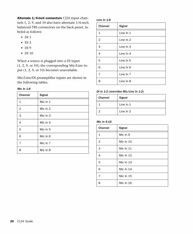
Alternate 1/4-inch connectors C|24 input chan-nels 1, 2, 9, and 10 also have alternate 1/4-inch balanced TRS connectors on the back panel, la-beled as follows:
• DI 1
• DI 2
• DI 9
• DI 10
When a source is plugged into a DI input (1, 2, 9, or 10), the corresponding Mic/Line in-put (1, 2, 9, or 10) becomes unavailable.
Mic/Line/DI preamplifier inputs are shown in the following tables.
Mic In 1-8
Channel Signal
1 Mic In 1
2 Mic In 2
3 Mic In 3
4 Mic In 4
5 Mic In 5
6 Mic In 6
7 Mic In 7
8 Mic In 8
C|24 Guide
Line In 1-8
Channel Signal
1 Line In 1
2 Line In 2
3 Line In 3
4 Line In 4
5 Line In 5
6 Line In 6
7 Line In 7
8 Line In 8
DI In 1-2 (overrides Mic/Line In 1-2)
Channel Signal
1 Line In 1
2 Line In 2
Mic In 9-16
Channel Signal
1 Mic In 9
2 Mic In 10
3 Mic In 11
4 Mic In 12
5 Mic In 13
6 Mic In 14
7 Mic In 15
8 Mic In 16

Mic/Line/DI Preamp Outputs
C|24 Mic/Line/DI preamplifier outputs appear in two groups of 8 line-level outputs (1-8, 9-16) on the back panel. Each group of outputs has a DB-25 female connector, labeled as follows:
• Line Out 1-8
• Line Out 9-16
Mic/Line/DI preamplifier outputs are shown in the following tables.
Line In 9-16
Channel Signal
1 Line In 9
2 Line In 10
3 Line In 11
4 Line In 12
5 Line In 13
6 Line In 14
7 Line In 15
8 Line In 16
DI In 9-10 (overrides Mic/Line In 9-10)
Channel Signal
1 Line In 9
2 Line In 10
Line Outputs
Line Out 1-8
Channel Signal
1 Line Out 1
2 Line Out 2
3 Line Out 3
4 Line Out 4
5 Line Out 5
6 Line Out 6
7 Line Out 7
8 Line Out 8
Line Out 9-16
Channel Signal
1 Line Out 9
2 Line Out 10
3 Line Out 11
4 Line Out 12
5 Line Out 13
6 Line Out 14
7 Line Out 15
8 Line Out 16
Chapter 4: Audio Connections 21

22
Line SubmixerC|24 provides an 8x2 Line Submixer that can be used to mix instrument inputs, auxiliary re-turns, or other external sources to stereo.
The output of the Line Submixer can then be connected to Pro Tools audio interface inputs for recording, or it can be monitored through the Monitor section of C|24.
The built-in Line Submixer operates indepen-dently of Pro Tools and can be used whenever C|24 is powered on.
Line Submixer Inputs
C|24 Line Submixer inputs appear as two groups of 4 stereo inputs (1-4, 5-8) on the back panel. Each group of stereo inputs has a DB-25 female connector, labeled as follows:
• Submix In 1-4 (ST)
• Submix In 5-8 (ST)
Each of the 8 submixer inputs has an indepen-dent gain control on the top panel.
Line Submixer input connections are shown in the following tables.
Submix In 1-4
Channel Signal
1 Submixer Input 1 (Left)
2 Submixer Input 1 (Right)
3 Submixer Input 2 (Left)
4 Submixer Input 2 (Right)
5 Submixer Input 3 (Left)
6 Submixer Input 3 (Right)
7 Submixer Input 4 (Left)
8 Submixer Input 4 (Right)
C|24 Guide
Line Submixer Outputs
Stereo Outputs C|24 Line Submixer outputs ap-pear as a pair of line-level outputs (L-R) on the back panel. Each output has a 1/4-inch balanced TRS connector, labeled as follows:
• Submix Out L
• Submix Out R
Stereo Output to Monitor Section C|24 Sub-mixer outputs (L-R) can also be routed to the Left and Right channels of the C|24 Monitor sec-tion using the “To Mon” switch on the top panel of C|24. This is useful for monitoring your studio equipment when you are not running Pro Tools.
The submixer output level is controlled with the Master level control on the top panel.
Submix In 5-8
Channel Signal
1 Submixer Input 5 (Left)
2 Submixer Input 5 (Right)
3 Submixer Input 6 (Left)
4 Submixer Input 6 (Right)
5 Submixer Input 7 (Left)
6 Submixer Input 7 (Right)
7 Submixer Input 8 (Left)
8 Submixer Input 8 (Right)
Submix Out 1-2
Channel Signal
1 Submix Out (Left)
2 Submix Out (Right)

Monitor SectionThe C|24 Monitor section is a six-channel con-trol room monitoring system that allows con-nection of up to four input sources (two 6-chan-nel or 4-channel surround, and two stereo), two cue inputs, and two outputs (one 6-channel sur-round and one stereo).
Monitor section Inputs are connected to Pro Tools audio interface outputs and other in-put sources in your studio. Monitor section Out-puts are connected to your speakers, cue system, headphones, and studio talkback and listenback systems.
The Monitor section operates independently of Pro Tools and can be used to monitor other in-put sources whenever C|24 is powered on.
Monitor Section Inputs
C|24 Monitor section inputs appear on three DB-25 female connectors on the back panel, labeled as follows:
• Pro Tools In (PT 1-6 + Cue 1-2)
• Surround In (Alt Sur 1-6)
• Ext Stereo In (Ext St 1 + St 2)
Input sources can be selected individually or summed using the Monitor source switches on the top panel of C|24.
Monitor section input connections are shown in the following tables.
Pro Tools In (PT 1-6 + Cue 1-2)
Main Inputs Connect the outputs from your Pro Tools system to the Main Inputs.
Cue Inputs Connect cue outputs from your Pro Tools system (such as a Send-based cue mix routed to audio interface outputs) to the Cue In-puts.
Surround In (Alt Sur 1-6)
Alternate Surround Inputs Connect an alternate input source (up to 5.1 surround) to the Alt Sur (Alternate Surround) Inputs.
Pro Tools In (PT 1-6 + Cue 1-2)
Channel Signal
1 Main Input Left (L)
2 Main Input Center (C)
3 Main Input Right (R)
4 Main Input Left Surround (Ls)
5 Main Input Right Surround (Rs)
6 Main Input LFE (LFE)
7 Cue Input Left
8 Cue Input Right
Surround In (Alt Sur 1-6)
Channel Signal
1 Alt Input Left (L)
2 Alt Input Center (C)
3 Alt Input Right (R)
4 Alt Input Left Surround (Ls)
5 Alt Input Right Surround (Rs)
6 Main Input LFE (LFE)
7 (Unused)
8 (Unused)
Chapter 4: Audio Connections 23

24
Ext Stereo In (Ext St 1 + St 2)
External Stereo Inputs Connect external stereo sources (such as a DAT or CD player) to the Ex-ternal Stereo Inputs.
Monitor Section Outputs
C|24 Monitor section outputs appear on two DB-25 female connectors on the back panel, la-beled as follows:
• Control Room Out (5.1 Mon Out L:1 R:3)
• Cue Outputs (Cue + SLS + TB)
The Monitor section output mode can be set to 5.1, LCRS, or Stereo using the Monitor mode switches on the top panel of C|24.
Monitor section output connections are shown in the following tables.
Ext Stereo In (Ext St 1 + St 2)
Channel Signal
1 Ext Stereo 1 In Left
2 Ext Stereo 1 In Right
3 Ext Stereo 2 In Left
4 Ext Stereo 2 In Right
5 (Unused)
6 (Unused)
7 (Unused)
8 (Unused)
C|24 Guide
Control Room Out (5.1 Mon Out L:1 R:3)
Main Outputs Connect the Main Outputs to your primary studio monitors (tables are shown below for 5.1, LCRS and Stereo Main monitor setups).
Alternate Outputs Connect the Alternate Out-puts to a secondary pair of studio monitors. The Alt Outputs (L-R) are also available on 1/4-inch balanced TRS connectors on the back panel, and mirror the output signal on the Alt Outputs on the Control Room Out connector.
Main Outputs (5.1) and Alternate Outputs
Control Room Out (5.1 Mon Out L:1 R:3)
Channel Signal
1 Main Output Left (L)
2 Main Output Center (C)
3 Main Output Right (R)
4 Main Output Left Surround (Ls)
5 Main Output Right Surround (Rs)
6 Main Output LFE (LFE)
7 Alt (Stereo) Output Left
8 Alt (Stereo) Output Right

Main Outputs (LCRS) and Alternate Outputs
Main Outputs (Stereo) and Alternate Outputs
Alternate Outputs (Stereo)
Control Room Out (5.1 Mon Out)
Channel Signal
1 Main Output Left (L)
2 Main Output Center (C)
3 Main Output Right (R)
4 Surround Output (S)
5 (Unused)
6 (Unused)
7 Alt (Stereo) Output Left
8 Alt (Stereo) Output Right
Control Room Out (5.1 Mon Out)
Channel Signal
1 Main Output Left (L)
2 (Unused)
3 Main Output Right (R)
4 (Unused)
5 (Unused)
6 (Unused)
7 Alt (Stereo) Output Left
8 Alt (Stereo) Output Right
Alt Outputs (Alt Out L-R on 1/4-inch TRS connectors)
Chan Signal
1 Alt (Stereo) Output Left
2 Alt (Stereo) Output Right
Cue Outputs (Cue + SLS +TB)
Cue Outputs Connect the Cue Outputs to the in-puts of your cue system.
Studio LS Outputs Connect Studio LS Outputs to speakers in your live room.
Talkback Slate Output Connect the Talkback Slate Output to an available Pro Tools input to record slate information.
Cue Outputs (Cue + SLS + TB)
Channel Signal
1 Cue Out Left
2 Cue Out Right
3 Studio LS Out Left
4 Studio LS Out Right
5 Talkback Slate Out
6 (Unused)
7 (Unused)
8 (Unused)
Chapter 4: Audio Connections 25

26
Listen and Talkback Microphones
C|24 provides connectors for a Listen micro-phone and an optional External Talkback micro-phone.
Listen Mic This XLR connector lets you connect a microphone to provide two-way communica-tion between the studio and the control room.
External Talkback Mic This XLR connector lets you connect an external microphone to use in place of the built-in Talkback microphone. Talk-back input is selected in the Talkback Prefer-ences in Utility mode. See “External Talkback Microphone” on page 116.
For more information on the Talkback function, see “Talkback Switch” on page 59.
Headphone Output
C|24 provides a headphone output with a 1/4-inch TRS connector on the front of the unit.
Headphone source is switchable between Con-trol Room outputs L and R (channels 1 and 3, pre-fader) and the Cue send (post-fader).
C|24 Guide

Chapter 5: Connecting Your Studio
Connection Examples for Stereo MonitoringYou can set up a basic stereo monitoring system using 2-channel input from Pro Tools. This in-put can be monitored on channels 1 (Left) and 3 (Right) of the C|24 Main Monitor outputs, or in the C|24 Alt Monitor (Stereo) outputs.
Another stereo source can be monitored by con-necting it to channels 1 (Left) and 3 (Right) of the Alternate Surround Inputs.
Additional stereo sources can be monitored by connecting them to the External Stereo 1 and 2 Inputs.
You can also connect a separate cue send from Pro Tools, and route it to the C|24 cue system outputs.
The following tables and diagram show exam-ples of connections for stereo monitoring.
Chapter 5: Connecting Your Studio 27

28
Monitoring System Inputs
Main Inputs and Cue Inputs
Alternate Inputs
External Stereo Inputs
Pro Tools In (PT 1-6 + Cue 1-2)
Chan Signal
1 Main Input Left (L) from Pro Tools Out 1
2 no connection
3 Main Input Right (R) from Pro Tools Out 2
4 no connection
5 no connection
6 no connection
7 Cue Input Left from Pro Tools Cue Out 1
8 Cue Input Right from Pro Tools Cue Out 2
Surround In (Alt Sur 1-6)
Chan Signal
1 Alt Input Left (L)
2 no connection
3 Alt Input Right (R)
4 no connection
5 no connection
6 no connection
Ext Stereo In (Ext St 1 + St 2)
Chan Signal
1 Ext Stereo 1 In Left from CD player
2 Ext Stereo 1 In Right from CD player
3 Ext Stereo 2 In Left from DAT deck
4 Ext Stereo 2 In Right from DAT deck
C|24 Guide
Monitoring System Outputs
Main Outputs (Stereo) and Alternate Outputs
Cue Outputs
Control Room Out (5.1 Mon Out L:1 R:3)
Chan Signal
1 Main Output Left (L) to Main speaker L
2 no connection
3 Main Output Right (R) to Main speaker R
4 no connection
5 no connection
6 no connection
7 Alt (Stereo) Output Left to Alt speaker L
8 Alt (Stereo) Output Right to Alt speaker R
Alt Outputs (Alt Out L-R on 1/4-inch TRS connectors)
Chan Signal
1 Alt (Stereo) Output Left to Alt speaker L
2 Alt (Stereo) Output Right to Alt speaker R
Cue Outputs (Cue + SLS + TB)
Channel Signal
1 Cue Out Left to cue system
2 Cue Out Right to cue system

Stereo Studio Connections
(Example Setup)Example studio setup with stereo monitoring
Pro Tools In
Headphone Out
DIMic In Line In
Preamp Line Out
C|24
Line Submixer InExt Stereo In
Monitor Alt Out
Monitor
to Pro Tools
Cue Out
Main OutCh 1,3
003Rack
L R
Pro ToolsStereo Out 1-2Cue Out 1-2
SubmixerOut
Alternate speakers
Main speakers
Cue system
CD playeror DAT deck
Chapter 5: Connecting Your Studio 29

30
Connection Examples for Surround MonitoringYou can set up a surround monitoring system using up to 6-channel input from Pro Tools. 5.1, LCRS, or Stereo input can be monitored in the C|24 Main Monitor outputs. Stereo input can also be monitored in the C|24 Alt Monitor (Stereo) outputs.
An additional surround source can be moni-tored by connecting it to the Alternate Surround Inputs.
External stereo sources can be monitored by connecting them to the External Stereo 1 and 2 Inputs.
You can also connect a separate cue send from Pro Tools, and route it to the C|24 cue system outputs.
The following tables and diagram show exam-ples of connections for surround monitoring.
C|24 Guide

Monitoring System InputsMonitor Inputs and Cue Inputs
Alternate Surround Inputs
External Stereo Inputs
Pro Tools In (PT 1-6 + Cue 1-2)
Chan Signal
1 Main Input Left (L) from Pro Tools Out 1
2 Main Input Center (C) from Pro Tools Out 2
3 Main Input Right (R) from Pro Tools Out 3
4 Main Input L Surr (Ls) from Pro Tools Out 4
5 Main Input R Surr (Rs) from Pro Tools Out 5
6 Main Input LFE (LFE) from Pro Tools Out 6
7 Cue Input Left from Pro Tools Cue Out 1
8 Cue Input Right from Pro Tools Cue Out 2
Surround In (Alt Sur 1-6)
Chan Signal
1 Alt Input Left (L) from DVD player
2 Alt Input Center (C) from DVD player
3 Alt Input Right (R) from DVD player
4 Alt Input Left Surround (Ls) from DVD player
5 Alt Input Right Surround (Rs) from DVD player
6 Alt Input LFE (LFE) from DVD player
Ext Stereo In (Ext St 1 + St 2)
Chan Signal
1 Ext Stereo 1 In Left from CD player
2 Ext Stereo 1 In Right from CD player
3 Ext Stereo 2 In Left from DAT deck
4 Ext Stereo 2 In Right from DAT deck
Monitoring System OutputsMain Outputs (5.1) and Alternate Outputs
Main Outputs (LCRS) and Alternate Outputs
Alternate Outputs (Stereo)
Control Room Out (5.1 Mon Out L:1 R:3)
Chan Signal
1 Main Output Left (L) to Left speaker
2 Main Output Center (C) to Center speaker
3 Main Output Right (R) to Right Speaker
4 Main Output Left Surround (Ls) to Left Surround speaker
5 Main Output Right Surround (Rs) to RightSurround speaker
6 Main Output LFE (LFE) to Subwoofer
7 Alt (Stereo) Output Left to Alt speaker L
8 Alt (Stereo) Output Right to Alt speaker R
Control Room Out (5.1 Mon Out L:1 R:3)
Chan Signal
1 Main Output Left (L) to Left speaker
2 Main Output Center (C) to Center speaker
3 Main Output Right (R) to Right Speaker
4 Main Output Left Surround (Ls) to Surround speaker (or split to 2 Surround speakers)
5 no connection
6 no connection
7 Alt (Stereo) Output Left to Alt speaker L
8 Alt (Stereo) Output Right to Alt speaker R
Alt Outputs (Alt Out L-R on 1/4-inch TRS connectors)
Chan Signal
1 Alt (Stereo) Output Left to Alt speaker L
2 Alt (Stereo) Output Right to Alt speaker R
Chapter 5: Connecting Your Studio 31

32
5.1 Surround Studio Connections
(Example Setup)C|24 Guide
Example studio setup with 5.1 surround monitoring
Pro Tools In
Headphone Out
DIMic In Line In
Preamp Line Out
C|24
192 I/O
Line Submixer InExt Stereo In
Monitor Alt Out
Monitor
L C R
Ls Rs LFE
to Pro Tools
Ext Talkback& Listen Mics
Main OutCh 1-6
1 2 34 5 6
AltSurround In
Pro ToolsCh 1-6 OutCue Out 1-2
Alternate speakers
CD playeror DAT deck
DVD player

Chapter 5: Connecting Your Studio 33

34
C|24 Guide
Part III: Reference
35

36

Chapter 6: C|24 Pro Tools Controls
Fader Section
Channel Strip
Channel Strip
Fader
Mute switch
Solo switch
Channel
Record Enableswitch
Encoder switch
Rotary Encoder
LCD display
Send switch
Dyn switch
Automation Mode
Input Monitorswitch
Insert switch
EQ switch
Automation
Select switch
Modeindicators
switch
Fader
Each channel has a touch-sensitive motorized fader for controlling channel volume in Normal mode and a wide range of parameters in Flip mode. When you are automating a parameter on a fader in Touch mode, touching the fader starts writing automation.
Mute Switch
The Mute switch toggles mute status for the channel. When a track is muted, its Mute switch lights solid. When a track is implicitly muted (because another track is soloed), its Mute switch flashes.
Solo Switch
The Solo switch toggles solo status for the chan-nel. When a channel is soloed, the Solo switch lights, and the Mute switches on other channels in the session flash to indicate implicit mute. The Solo switch function follows the Pro Tools Solo Latch options (Latch, X-OR, and Momen-tary).
Solo Safe Mode To solo safe a track, hold the Command/Ctrl Modifier switch and press the track’s Solo switch. When a track is solo safed, its Solo switch flashes once.
Chapter 6: C|24 Pro Tools Controls 37

38
Channel Select Switch
The Channel Select switch selects the channel in Pro Tools, and lights when the channel is se-lected. The Channel Select switch can be set to follow latching or X-OR (non-latching) behav-ior. See “Console Preferences” on page 47.
Input Monitor Switch
The function of the Input Monitor switch de-pends on the type of track displayed in the channel strip.
Audio Tracks (Pro Tools HD Only) The Input Monitor switch toggles the input monitoring mode (TrackInput) for the channel between Auto Input and Input Only mode. When the channel is in Input Only mode, the Input Mon-itor switch lights.
Instrument Tracks The Input Monitor switch transfers control of MIDI Volume to the fader, MIDI Pan to the rotary encoder, and MIDI Mute to the channel Mute switch. It also changes In-put and Output assign modes to apply to MIDI Inputs and Outputs on the Instrument track. When MIDI controls are displayed on the chan-nel fader and encoder, the Input Monitor switch flashes.
Record Enable Switch
The Record Enable switch toggles record enable status for the channel. When a track is record-enabled and Pro Tools is idle or playing back, the Record Enable switch flashes. During record-ing, the Record Enable switch lights continu-ously.
Record Safe Mode To record safe a track, hold the Command/Ctrl Modifier switch and press the track’s Record Enable switch.
C|24 Guide
Rotary Encoder Section
Rotary Encoder
Each Channel has a rotary encoder. The func-tion of the rotary encoders depends on the cur-rent mode and view.
Console Views Rotary encoders control channel pan, send level and assignments, depending on which Console view is enabled (Pan view or Sends view). If your system includes a Digide-sign PRE, mic pre level can be controlled from the rotary encoders in Console view.
Channel View Rotary encoders control plug-in, pan, send, or plug-in settings and assignments, depending on which Channel view is enabled (Pan/Send view or Insert Select view). If your system includes a Digidesign PRE, most mic pre controls can be accessed in Channel View.
Flip Mode Rotary encoders control track Volume or Send pan position when Flip mode is enabled.
Rotary Encoder LEDs
Each rotary encoder has a ring of 11 LEDs for in-dicating data values controlled by the encoder. Discrete or stepped information such as pan po-sition or frequency is shown by a single LED. Continuously variable values such as send level, gain, or filter bandwidth are shown by an ex-panding series of LEDs.
Rotary Encoder section
RotaryEncoderSelect/Auto
switch
Pre/Postswitch
Send Muteswitch
Encoderswitch

Encoder LED rings can show send level, pan po-sition, and plug-in parameter values. In Flip mode, they can show track level or Send pan po-sition.
Encoder Switch
The switches under each encoder perform a va-riety of functions, depending on what is shown in the LCD displays. Functions of the encoder switch include:
• Sends Console view: Toggling Send mute or Send pre/post status
• Pan/Send Channel view: Toggling Send mute or Send pre/post status
• Parameter view: Cycling stepped plug-in parameters, setting up multi-mono plug-in operation
• Mic Pre view: If your system includes a Digidesign PRE, controlling mic pre set-tings
• Groups view: Selecting Group IDs for new groups, enabling or selecting current Groups
• Soft Keys view: Cycling preferences or per-forming actions
• Default switch: Setting parameters to their default values
• Window Configuration view: Creating, ed-iting, and recalling Window configurations
• Memory Location view: Creating, editing, and recalling Memory Locations
Switch Functions Section
The Switch Functions section has three switches that set the function of the encoder switches in certain views.
Select/Auto Switch
The Select/Auto switch is available only when C|24 is in Parameter view.
Select When the Select/Auto switch is unlit, it is in Select mode. In this mode, encoder switches toggle plug-in parameters displayed above the corresponding encoder.
Auto When the Select/Auto switch is lit, it is in Auto mode. In this mode, encoder switches do either of the following:
• If Pro Tools is idle or playing back, the en-coder switches enable the corresponding plug-in parameters for automation. The switch lights to indicate enabled status.
• If an automation pass is in progress, the en-coder switches flash to indicate writing of plug-in automation. You can press a flash-ing encoder switch to punch the plug-in parameter out of writing.
Pre/Post Switch
The Pre/Post switch is available only when C|24 is in Sends Console view.
When the Pre/Post switch is lit, the encoder switches toggle the corresponding Send between pre- and post-fader operation. When the en-coder switch is unlit, the Send is set to post-fader operation. When the encoder switch is lit, the Send is set to pre-fader operation.
When you hold down the Pre/Post switch, the pre/post status of all Sends is displayed.
Send Mute Switch
The Send Mute switch is available only when C|24 is in Sends Console view.
When the Send Mute switch is lit, the encoder switches toggle the mute status of the corre-sponding Send. When the encoder switch is un-lit, the Send is not muted When the encoder switch is lit, the Send is muted.
To view the mute status of all displayed Sends, hold down the Send Mute switch.
Chapter 6: C|24 Pro Tools Controls 39

40
LED Displays
The LED displays provide two rows of 6 charac-ters for each channel strip.
LED Display Mode Switch
To cycle forward through LED display modes:
Press the Display Mode switch.
To cycle backward through the LED display modes:
Hold the Shift (add) Modifier switch and press the Display Mode switch.
The available display modes depend on the cur-rent view.
Home (Pan Console) View
In Pan Console view, the Display Mode switch cycles through the following channel display modes:
Name Mode Shows the track name only on the top row. Volume and Pan values are displayed on the bottom row when the fader is touched or the encoder is moved, according to the TchVal preference.
Volume Mode Shows the track name on the top row and track volume on the bottom row.
Pan Mode Shows the track name on the top row and track pan on the bottom row.
Headroom Mode Shows the track name on the top row and track headroom on the bottom row.
LED displays and Display Mode switch
Display Modeswitch
LED displays
C|24 Guide
Mem Loc/Win Cfg Mode Shows the track name on the top row and available Memory Locations or Window Configurations on the bottom row.
Sends Console View
In Sends Console view, the Display Mode switch cycles through the following Send display modes:
Send Path Shows the track name on the top row and the I/O or bus path for the Send on the bot-tom row.
Send Volume Shows the track name on the top row and the Send volume on the bottom row.
Blank Shows track name only on the top row.
Channel Information
In any view, you can also press and hold the Dis-play Mode switch to show channel state infor-mation, including current view display, LED dis-play data, rotary and fader controls, and plug-in information.
Insert Switch
Each channel has an Insert switch that lets you select and view inserts on that channel. The switch lights to indicate that there is at least one non-EQ, non-Dynamics plug-in on the channel.
Insert switch
Insert/SendBypassswitch
Insert switch

When you press a lit Insert switch, C|24 enters Insert Select view, and displays the channel’s in-serts across the LCD displays. From Insert Select view, you can display all the controls of a single plug-in in Parameter view. See “Insert Select View” on page 78 and “Parameter View” on page 80.
In Parameter view, when you press and hold a lit Insert switch, the LCD displays show informa-tion on the currently focused insert.
Insert/Send Bypass Switch
The Insert and Send Bypass switch changes the function of the Insert switches on all channels, putting them in Bypass mode. When the In-sert/Send Bypass switch is lit, the Insert switch toggles the Bypass state of all plug-ins on the channel. In Bypass mode, when the plug-ins on a track are bypassed, the track’s Insert switch is lit.
See “Bypassing Plug-ins” on page 79.
Send Switch
Each channel has a Send switch that lets you se-lect and view Sends on that channel.The switch lights to indicate that there is at least one Send on the channel.
When you press a lit Send switch, C|24 enters Pan/Send Channel view, and displays the chan-nel’s Sends across the LCD displays. See “Pan/Send Channel View” on page 73.
Send switch
Insert/SendBypassswitch
Send switch
When you double-press a Send switch, C|24 en-ters Expanded Pan view, and displays the pan controls for a track. See “Expanded Pan View” on page 75.
Insert/Send Bypass Switch
The Insert and Send Bypass switch changes the function of the Send switches on all channels, putting them in Bypass mode. When the In-sert/Send Bypass switch is lit, the Send switch toggles the mute status of all Sends on the chan-nel. In Bypass mode, when the sends on a track are muted, the track’s Send switch is lit.
See “Muting Sends in Pan/Send Channel View” on page 74.
EQ and Dynamics Switches
Each channel has EQ and Dynamics switches that let you focus any plug-ins of the corre-sponding type assigned to that channel. The EQ or Dyn switch lights to indicate that there is at least one plug-in of the corresponding type on the channel. When you press a lit EQ or Dyn switch, C|24 enters Parameter view, and displays the plug-in’s controls across the LCD displays. See “Viewing EQ and Dynamics Plug-ins” on page 81.
In Parameter view, when you press and hold a lit EQ or Dyn switch, the LCD displays show infor-mation on the currently focused plug-in.
EQ and Dynamics switches
Dyn switch
EQ switch
EQ/DynBypassswitch
Chapter 6: C|24 Pro Tools Controls 41

42
EQ and Dynamics Bypass Switch
The EQ and Dynamics Bypass switch changes the function of the EQ and Dynamics switches on all channels, putting them in Bypass mode.
EQ Switch When the EQ and Dyn Bypass switch is lit, the EQ switch toggles the Bypass state of all EQ plug-ins on the channel. In Bypass mode, when the EQ plug-ins on a track are bypassed, the track’s EQ switch is lit.
Dynamics Switch When the EQ and Dyn Bypass switch is lit, the Dyn switch toggles the Bypass state of all Dynamics plug-ins on the channel. In Bypass mode, when the Dynamics plug-ins on a track are bypassed, the track’s Dyn switch is lit.
See “Bypassing EQ and Dynamics Plug-ins” on page 81.
Channel Automation Mode Switch and Indicators
Each channel has an Automation Mode switch and series of Automation Mode indicators (Write, Touch, Latch, Trim and Read).
The Automation Mode switch cycles the chan-nel through the following Pro Tools automation modes:
• Write
• Touch
• Latch
• Touch/Latch (Pro Tools HD only)
• Read
• Off
Automation Mode switch and indicators
Automation Mode switch
Automation Mode indicators
C|24 Guide
See “Working with Automation” on page 103.
The Automation Mode switch lets you cycle the channel through Touch, Latch, Touch/Latch, Read and Off modes during playback, but it pre-vents you from entering Write mode during playback. To directly enter Write mode during playback, use the Global Automation Mode switch (See “Automation Mode Switches” on page 42.)
When in Write mode, the corresponding indica-tor flashes at all times. When in Touch, Latch, or Touch/Latch modes, the corresponding indica-tor lights until automation writing begins. When automation writing begins on the chan-nel, the indicator flashes. If automation is turned off for the channel (Off), none of the in-dicators is lit.
Global Automation Switches
Automation Mode Switches
The Automation Mode switches are used to dis-play and set automation modes. These switches light to indicate that at least one channel is in that automation mode. If multiple channels are selected and set to different automation modes, all applicable mode switches are lit.
Automation Mode switches
Automation Trim Modeswitch
AutomationLatch Mode
switch
AutomationTouch Mode
switch
AutomationWrite Mode
switch
Automation Read ModeswitchAutomation Offswitch

The Automation Mode switches mirror the function of the on-screen Automation Mode se-lector for each track, and let you change auto-mation modes of channels during playback.
See “Working with Automation” on page 103.
Write Switch Indicates or sets the automation mode of a track to Write mode.
Touch Switch Indicates or sets the automation mode of a track to Touch mode.
Latch Switch Indicates or sets the automation mode of a track to Latch mode.
Trim Switch (Pro Tools HD Only) Indicates or sets the automation mode of a track to Trim mode.
Read Switch Indicates or sets the automation mode of a track to Read mode.
Off Switch Sets the automation mode of a track to Off.
Automation Enable Switches
The Automation Enable switches are used to en-able or suspend writing of each type of automa-tion on all channels. The Automation Enable switches mirror the function of the correspond-ing buttons in the Automation window.
Automation Enable switches
Enable Plug-inAutomation
Enable Send LevelAutomation
Enable Send MuteAutomation
Enable VolumeAutomation
Enable PanAutomation
Enable MuteAutomation
Enable Send PanAutomation
switch
switch
switch
switch
switch
switch
switch
SuspendAutomation
switch
When writing is enabled for an automation type but it is not currently writing on any track in the session, the corresponding switch lights solid. When writing is enabled for an automation type and it is currently writing on any track in the session, the corresponding switch flashes.
Volume Switch Enables and suspends writing of channel volume automation on all tracks in the session.
Pan Switch Enables and suspends writing of channel pan automation on all tracks in the ses-sion.
Mute Switch Enables and suspends writing of channel mute automation on all tracks in the session.
Send Level Switch Enables and suspends writing of send level automation on all tracks in the ses-sion.
Send Pan Switch Enables and suspends writing of send pan automation on all tracks in the ses-sion.
Send Mute Switch Enables and suspends writing of send mute automation on all channels.
Plug-in Switch Enables and suspends writing of automation for any automation-enabled plug-in parameters on all tracks in the session.
Suspend Switch Suspends writing and playback of all automation in the session.
Chapter 6: C|24 Pro Tools Controls 43

44
Automation Write To Switches(Pro Tools HD Only)
The Automation Write To switches invoke the manual “Write to Start/End/All/Punch” commands and the automatic “Write to Start/End/All/Punch on Stop” automation com-mands in Pro Tools. These switches mirror the function of the corresponding buttons in the Automation window.
See “Working with Automation” on page 103.
All Switch Writes the current automation value of all write-enabled parameters to an entire se-lection or track when performing an automa-tion pass.
Start Switch Writes the current automation value of all write-enabled parameters to the start of a selection or track when performing an auto-mation pass.
End Switch Writes the current automation value of all write-enabled parameters to the end of a selection or track when performing an automa-tion pass.
Punch Switch Writes the current automation value of all write-enabled parameters back to the punch point (the location in the track where the current automation pass started).
Next Switch Writes the current automation value of all write-enabled parameters forward to the next automation breakpoint.
Automation Write To switches
AutomationWrite To All
Automation Write to Next
AutomationWrite To End
switch
switch
switch
AutomationWrite to Punch
switch
AutomationWrite to Start
switch
C|24 Guide
Modifier Switches
The Modifier keys duplicate the function of the Pro Tools computer keyboard modifiers.
Shift (add) Switch (Mac and Windows)
The Shift (add) Modifier switch duplicates the function of the Shift key on the computer key-board.
Control (Mac) or Win (Windows) Switch
The Ctrl/Win Modifier switch duplicates the function of the Control key (Mac) or the Win-dows key, also called the Start key, (Windows) on the computer keyboard.
Option (Mac) or Alt (Windows) Switch
The Opt/Alt (all) Modifier switch duplicates the function or the Option key (Mac) or the Alt key (Windows) on the computer keyboard.
Command (Mac) or Control (Windows) Switch
The Command/Ctrl Modifier switch duplicates the function of the Command key (Mac) or the Control (Windows) key on the computer key-board.
Modifier switches
Shift (add)switch
Control/Winswitch
Option/Alt (all)switch
Command/Ctrlswitch

Channel BarThe Channel Bar spans the center of the Fader section of C|24, and includes controls for inserts, chan-nel assignments, pan display, send display, and Soft Key functions.
Channel Bar
Insertssection
Assignsection
Pansection
Soft Keysswitch
Sendssection
Channel BarScroll
switches
Inserts Section
Master Bypass Switch
The Master Bypass switch bypasses plug-ins in one of two ways, depending on the current view.
Insert Select View The Master Bypass switch by-passes all plug-ins on the focused channel.
Parameter View The Master Bypass switch by-passes only the plug-in currently shown in the LCD displays.
The Master Bypass switch lights to indicate that the currently displayed plug-in is bypassed. The Master Bypass switch flashes to indicate that at least one channel of a currently displayed multi-mono plug-in is bypassed.
Inserts section of the Channel Bar
Master Bypassswitch
Compareswitch
Safeswitch
Insert/Parameter
switch
Compare Switch
The Compare switch lets you compare any plug-in changes to the currently loaded plug-in set-tings. This mirrors the function of the Compare button in Pro Tools plug-in windows. The Com-pare switch lights to indicate that controls on a plug-in have been changed but not saved as a preset.
Safe Switch
The Safe switch enables plug-in automation safe mode for the currently displayed plug-in. The Safe switch lights when an automation safed plug-in is focused.
Insert/Parameter Switch
The Insert/Parameter switch toggles the C|24 view between Insert Select view and Parameter view, and accesses multi-mono plug-in setup page. When an insert’s parameters are shown in the LCD displays, the Insert/Param switch lights.
See “Parameter View” on page 80 and “Setting Up Multi-mono Plug-ins” on page 81.
Chapter 6: C|24 Pro Tools Controls 45

46
Assign Section
Assign Switch
The Assign switch puts C|24 into Assign mode, which lets you assign inputs, outputs, inserts, and sends from the rotary encoders.
See “Assign Mode” on page 87.
Input and Output Switches
The Input and Output switches display channel input and output pathnames in the bottom row of the LCD displays.
In Assign mode, the Input and Output switches bring the inputs and outputs to the rotary en-coders for assignment.
Escape/Cancel Switch
The Escape/Cancel switch is used to exit modes and to cancel operations or on-screen dialogs.
When an action has occurred that can be exited or canceled with the Escape/Cancel switch, the switch flashes.
Assign section of the Channel Bar
Assignswitch
Inputswitch
Outputswitch
Escape/Cancelswitch
C|24 Guide
Pan Section
When in Pan Console view or Pan/Send Chan-nel view, the switches in the Pan section deter-mine which pan controls are assigned to the channel encoders. The corresponding pan, di-vergence, or percentage values are shown in the LCD displays.
L(C)R Switch
The L(C)R switch assigns Left-Right pan (stereo tracks) or Front pan (multichannel tracks) to the encoder. When the Divergence switch is lit, this switch assigns Front divergence control to the encoder.
Front-Rear Switch
The Front-Rear switch assigns Front-Rear pan to the encoder. When the Divergence switch is lit, this switch assigns Front-Rear divergence con-trol to the encoder.
Rear Switch
The Rear switch assigns Rear pan to the encoder. When the Divergence switch is lit, this switch assigns Rear divergence control to the encoder.
Divergence Switch
The Divergence switch puts the L(C)R, Front-Rear, and Rear switches into Divergence mode, which lets you adjust divergence for the corre-sponding parameters.
Pan section of the Channel Bar
L(C)Rswitch
Front-Rearswitch
Rearswitch
Divergenceswitch
Center %switch
LFEswitch
L/Rswitch
Soft Keysswitch

Center Percentage Switch
The Center Percentage (%) switch assigns the Center Percentage parameter to the encoder.
LFE Switch
The LFE switch assigns LFE volume control to the encoder.
L/R Switch
The L/R switch toggles display of the Left and Right pan control on the track’s encoder. When L/R switch is unlit, the track pan controls the Left pan control (stereo tracks). When L/R switch is lit, the track pan controls the Right pan control (stereo tracks).
Soft Keys Switch
The Soft Keys switch provides access to C|24 preferences, Pro Tools actions and Automation preferences directly from the LCD displays.
To set a preference or action from the Soft Keys:
1 Press the Soft Keys switch.
2 Press the encoder switch that corresponds to the displayed item to cycle the preference set-ting or perform the command.
3 Press the Soft Keys switch to exit.
You can exit Soft Keys directly by entering any other view or mode on C|24, except for Master Faders mode. The Masters switch does not exit Soft Keys.
The following console preferences, actions and and automation preferences are available:
Console Preferences
Faders (Faders On/Off) Temporarily turns off C|24 faders to prevent fader movement when monitoring a mix.
TchVal (Touch Display of Parameter Values) De-termines the temporary display of control pa-rameter values on a track when its fader is touched or its encoder is moved. TchVal can be set to the following:
• On: All parameter values display when a control is touched
• Off: Touch has no effect
• NoVol: All parameter values except volume values display when a control is touched
Select (Select Switch Latch Mode) Determines whether channel Select switches follow latching or X-OR (non-latching) behavior.
When this preference is set to “Latch,” chan-nel Select buttons will latch on when pressed.
When this preference is set to “X-OR,” press-ing a channel Select switches disables other channel Select switches. To select multiple chan-nels in X-OR mode, press and hold multiple Se-lect switches.
TkDsp (Track Display) Cycles the display of track names in the Console views to include Name (name only), Number (track position number and an abbreviated name), or Grp ID (Group ID letter and an abbreviated track name).
Chapter 6: C|24 Pro Tools Controls 47

48
ChanWn (Channel Window Display) Determines whether displaying plug-in or send parameters opens the corresponding plug-in or send win-dow on-screen in Pro Tools.
When this preference is set to “Yes,” the on-screen display of plug-in and send windows changes to reflect the state of the control surface.
When this preference is set to “No,” the on-screen display of plug-in and send windows does not change to reflect the state of the control surface.
2KbPan (Two-Knob Panning) (Pro Tools HD Only)
Toggles linking of front and rear pan controls in surround panner windows to facilitate left-right motion in the surround field.
Actions
(Pro Tools HD Only)
Prview (Preview) Puts Pro Tools in Preview mode.
PchPrv (Punch Preview) Executes the Punch Pre-view command.
SusPrv (Preview Suspend) Suspends Preview mode.
Captre (Capture) Executes the Capture com-mand.
PchCap (Punch Capture) Executes the Punch Capture command.
Join Executes the Join command.
C|24 Guide
Automation Preferences
(Pro Tools HD Only)
AutoJn (Auto Join) Sets tracks in Latch mode to automatically resume writing of automation af-ter the transport is stopped and started again during an automation pass.
LchStp (Allow Latch Prime in Stop) Toggles the Allow Latch Prime in Stop preference, which al-lows tracks in Latch mode to be primed for writ-ing automation while the transport is stopped.
ColVCA (Coalesce when Removing Slaves from VCA Group) Toggles the preference that auto-matically coalesces automation to slave track when they are removed from a VCA-controlled group.
ColTrm (Coalesce Trim Automation) Sets the pref-erence that determines when Trim automation is coalesced. The preference settings are as fol-lows:
• EveryP: After Every Pass
• OnExit: On Exiting Trim Mode
• Manual: Manually

Sends Section
The Sends section switches are used in Console view to focus sends in the LCD displays. Send volume is controlled by the encoders.
F-J switch
The F-J switch selects the bank of Sends accessi-ble from the Sends switches.
When the F-J switch is off, the Sends switches control Sends A through E. When the F-J switch is on, the Sends switches control Sends F through J.
Sends Switches
The Sends switches (A-E, F-J) are used to focus a single Send position in the LCD displays, across all tracks. The switches light to indicate the cur-rently focused Send.
Channel Bar Scroll Switches
The Channel Bar Scroll switches are used to bank the display of parameters, sends, memory locations, window configurations, or groups in the LCD displays.
The Channel Bar Scroll switches light when ad-ditional parameters are available in the corre-sponding direction.
Sends section of the Channel Bar
F-Jswitch
Sendsswitches (A-E/F-J)
Miscellaneous Controls
Edit Mode Switches
The Edit Mode switches place Pro Tools directly in the corresponding Edit mode. The switch lights to indicate the current mode.
Shuffle Switch Places Pro Tools in Shuffle mode.
Spot Switch Places Pro Tools in Spot mode.
Slip Switch Places Pro Tools in Slip mode.
Grid Switch Toggles Pro Tools between Absolute and Relative Grid mode.
See “Selecting Edit Tools” on page 101.
Edit Mode switches
Shuffleswitch
Spotswitch
Slipswitch
Gridswitch
Chapter 6: C|24 Pro Tools Controls 49

50
View and Edit Switches
View Switches
Home Switch
The Home switch puts C|24 into Pan/Console view, which is the default view. In this view, fad-ers control channel volume, rotary encoders control channel pan.
See “Pan Console View” on page 71.
Focus Switch
The Focus switch returns C|24 to the previously focused view (Parameter view, Expanded Send view, Expanded Pan view, or Mic Pre view) after you change to a Console view. The Focus switch lights to indicate that it is possible to return to a focused view.
Mic Pre Switch
The Mic Pre switch toggles C|24 into Mic Pre view, which shows the controls of any con-nected Digidesign PRE.
See “Mic Pre View” on page 82.
View and Edit switches
Homeswitch
Focusswitch
Mic Preswitch
Copyswitch
Pasteswitch
C|24 Guide
Edit Switches
The Edit switches directly execute the corre-sponding command in Pro Tools. The switches light to indicate which functions are available.
Copy and Paste Switches
The Copy and Paste switches carry out the Copy and Paste commands in the Pro Tools Edit menu.
See “Cutting and Pasting” on page 101.
Tools & Functions Switches
Alternate Function Switch
The Alternate Function switch selects the top or bottom command for the dual-function switches in this section.
When the Alternate Function switch is off, the top function is active for all switches in this sec-tion.
When the Alternate Function switch is on, the bottom function is active for all switches in this section.
Edit Tools
Trim Selects the Trim tool and cycles through the versions of the tool.
Select Selects the Selector tool.
Tools and Functions switches
Trim/All Notes Off
Select/Wait For Note
Grabber/Click
Pencil/Count Off
Smart/Merge-Rec
Link Edit-TL/Tab to Trsnt
Link Trk-Edit/Zoom Tog
Alt Function

Grabber Selects the Grabber tool and cycles through the versions of the tool.
Pencil Selects the Pencil tool and cycles through the versions of the tool.
Smart Selects the Smart Tool.
The Smart Tool can also be selected by simulta-neously pressing any combination of the Trim, Select, and Grabber switches.
Link Edit and Timeline
The Link Edit and Timeline switch toggles the Link Timeline and Edit Selection option. The switch lights when the option is selected.
Link Track and Edit Selection
The Link Track and Edit Selection switch toggles the Link Track and Edit Selection option. The switch lights when the option is selected.
MIDI Commands and Controls
All Notes Off Executes the All MIDI Notes Off command.
Wait For Note Enables Wait for Note in the Transport window. The switch lights when Wait for Note is enabled.
Click Enables the Metronome Click in the Trans-port window. The switch lights when Metro-nome Click is enabled.
Count Off Enables the Countoff in the Transport window. The switch lights when Countoff is en-abled.
Merge-Record Enables MIDI Merge recording in the Transport window. The switch lights when MIDI Merge is enabled.
Tab to Transients
The Tab to Transients switch toggles the Tab to Transients option. The switch lights when the option is selected.
Zoom Toggle
The Zoom Toggle switch controls the Zoom Tog-gle state. The switch lights when Zoom Toggle is enabled.
Window Switches
Alternate Function Switch
The Alternate Function switch selects the top or bottom command for the dual-function switches in this section.
When the Alternate Function switch is off, the top function is active for all switches in this sec-tion.
When the Alternate Function switch is on, the bottom function is active for all switches in this section.
Pro Tools Windows
Mix Opens the Mix Window or brings it to the front.
Edit Opens the Edit Window or brings it to the front.
Window switches
Mix/Workspace
Edit/Task Mgr
Plug-in/Big Counter
Pan/Automation
Transport/Undo
Win Config/Properties
Mem Loc/MIDI Ops
Alt Function
Chapter 6: C|24 Pro Tools Controls 51

52
Plug-in Opens and closes the window for the cur-rently focused plug-in.
Pan Opens and closes the window for the cur-rently focused pan controls.
Transport The Transport switch opens and closes the Transport window, and lets you show/hide sections of the Transport window. See “Display-ing the Transport Window” on page 94.
Window Configuration The Window Configura-tion (Win Cfg) switch opens and closes the Win-dow Configuration list and lets you display and select Window Configurations in the LCD dis-plays. See “Window Configuration View” on page 84.
Memory Locations The Memory Locations (Mem Loc) switch opens and closes the Memory Loca-tions window and lets you display and select Memory Locations in the LCD displays. See “Memory Location View” on page 85.
Workspace The Workspace switch opens and closes the DigiBase Workspace Browser.
Task Manager The Task Manager (Task Mgr) switch opens and closes the DigiBase Task Man-ager window.
Big Counter The Big Counter switch opens and closes the Big Counter window.
Automation The Automation switch opens and closes the Automation window.
Undo The Undo switch opens and closes the Undo History window.
Properties The Properties switch opens and closes the MIDI Real-Time Properties window.
MIDI Operations The MIDI Operations switch opens and closes the MIDI Operations window.
C|24 Guide
Global Controls
Do To All and Do To Selected Switches
The Do To All and the Do To Selected switches are used to apply actions to multiple tracks in a Pro Tools session.
The Do To All and Do To Selected switches can follow momentary or latching behavior.
When single-pressed, their effect applies only to the next operation.
When held, they apply to all operations car-ried out while being held.
When double-pressed, they latch on and flash until pressed a second time.
Default Switch
The Default switch is used to reset displayed pa-rameters to their default values.
The Default switch can follow momentary or latching behavior. When single-pressed, its ef-fect applies only to the next operation. When double-pressed, it latches on and flashes until pressed a second time.
Global controls
Do To
Defaultswitch
Solo Clearswitch
Plug-in Safeswitch
Vel Sensswitch
Input Monswitch
Master Recswitch
Do To Allswitch
Selectedswitch

Solo Clear Switch
The Solo Clear switch clears all latched Solo switches in the session. This switch flashes when any channel is soloed.
Plug-in Safe Switch
The Plug-In Safe switch enables plug-in automa-tion safe mode for the currently focused plug-in. This switch is lit when an automation safe plug-in is focused.
Velocity Sensitive Switch
The Velocity Sensitive (Vel Sens) switch toggles all Rotary Encoders between fixed-velocity mode and velocity sensitive mode, where the re-sponsiveness of the encoder is proportional to the speed of rotation.
Input Monitor Switch
Pro Tools HD
In Pro Tools HD, the Input Monitor switch tog-gles the Input Monitor option between “Set Record Tracks to Auto Input” and “Set Record Tracks to To Input Only” on all record-enabled tracks.
Pro Tools LE
In Pro Tools LE, the Input Monitor switch tog-gles Pro Tools between Input Only Monitoring and Auto Input Monitoring.
Master Record Enable Switch
The Master Record Enable switch toggles record enable status for all applicable audio tracks in a session. This switch flashes when channels are record-enabled and the Pro Tools transport is stopped, and lights continuously during record-ing.
Groups
Create Switch
The Create switch lets you use C|24 to select a Group ID and select tracks to create new Mix/Edit Groups. See “Creating Groups” on page 83.
Enable Switch
The Enable switch lets you toggle the enabled status of current groups. See “Enabling and Sus-pending Groups” on page 83.
Modify Switch
The Modify switch lets you use C|24 to modify Mix/Edit groups. See “Modifying Groups” on page 84.
Delete Switch
The Delete switch executes the Delete Groups command. See “Deleting Groups” on page 84.
Suspend Switch
The Suspend switch suspends all groups in the session.
Groups switches
Deleting groups cannot be undone.
Create Groups switch
Enable Groups switch
Modify Groups switch
Delete Groups switch
Suspend Groups switch
Chapter 6: C|24 Pro Tools Controls 53

54
Transport and Navigation Controls
Transport Mode Switches
Audition Switch
The Audition switch toggles Audition mode on and off. When Audition mode is on, this switch lights.
In Audition mode, you can listen to either the start or end of a selection, with or without pre-roll or post-roll, by pressing the following switches:
Transport Mode switches
Auditionswitch
RTZ/Eswitch
Trans=switch
Onlineswitch
Mark Inswitch
Mark Outswitch
Post-Rollswitch
Pre-Rollswitch
Loop Playbackswitch
Loop Recordswitch
QuickPunchswitch
Dyn Transswitch
C|24 Guide
Pre-Roll Switch Plays audio starting at the pre-roll point up to the beginning of the selection.
Mark In Switch Plays audio starting at the selec-tion start through the length of the post-roll amount.
Mark Out Switch Plays audio back-timed from the selection end by the pre-roll amount.
Post-Roll Switch Plays audio starting at the end of a selection through the post-roll amount.
Return to Zero/Go To End Switch
The Return to Zero/Go To End switch locates the cursor to the beginning or the end of the ses-sion. See “Navigating with the Transport” on page 99.
Transport Master Switch
The Transport Master (Transport =) switch cy-cles the Transport Master through the available options, which can include Pro Tools, Machine, MMC, or Remote. The Transport Equals switch lights when the Transport Master is set to Ma-chine, MMC, or Remote.
Online Switch
The Online switch toggles the Pro Tools trans-port online status when triggering playback from an external source. The Online switch flashes when the transport is waiting for sync, and lights to indicate that the transport is on-line.
Pre-Roll and Post-Roll Switches
The Pre-Roll and Post-Roll switches toggle the enable status of pre-roll and post-roll in the Pro Tools transport. The Pre-Roll and Post-Roll switches light to indicate they are enabled.

In Audition mode, the Pre-Roll and Post-Roll switches activate playback of various parts of an edit selection. See “Audition Switch” on page 54.
Mark In and Mark Out Switches
In Audition mode, the Mark In and Mark Out switches activate playback of various parts of an edit selection, and in conjunction with the Scrub/Shuttle wheel, let you create selections. See “Selecting Audio” on page 99.
Dynamic Transport Switch
The Dynamic Transport switch toggles Dynamic Transport mode on and off.
Loop Playback Switch
The Loop Playback switch toggles Loop Playback mode on and off. The Loop Playback state is mir-rored in the Play button in the Pro Tools Trans-port window. When Loop Playback mode is ac-tive, this switch lights.
Loop Record Switch
The Loop Record switch toggles Loop Record mode on and off. The Loop Record state is mir-rored in the Record button in the Pro Tools Transport window. When Loop Record mode is active, this switch lights.
QuickPunch Switch
The QuickPunch switch toggles QuickPunch record mode on and off. When QuickPunch mode is active, this switch lights. The Quick-Punch state is mirrored in the Record button in the Pro Tools Transport window.
Zoom Preset Switches
The Zoom Preset switches let you set and recall the five horizontal Zoom presets in Pro Tools.
File/Utility Switches
Undo Switch
The Undo switch executes the Undo command in Pro Tools.
Redo Switch
The Redo switch executes the Redo command in Pro Tools.
Utility Switch
The Utility switch places C|24 in Utility mode. When C|24 is in Utility mode, this switch flashes.
Zoom Preset switches
File/Utility switches
Zoom Preset 1
Zoom Preset 3
Zoom Preset 5
Zoom Preset 2
Zoom Preset 4
Enterswitch
Esc/Cancelswitch
Saveswitch
Undoswitch Utility
switchRedo
switch
Chapter 6: C|24 Pro Tools Controls 55

56
Utility mode lets you view C|24 system informa-tion, run diagnostic tests, and set certain C|24 preferences. For complete information, see Appendix B, “Utility Mode.”
Enter Switch
The Enter switch is used to confirm operations, and is equivalent to clicking OK in Pro Tools di-alogs.
The Enter switch is also used to create new Memory Locations, and is equivalent to the En-ter key on the computer numeric keypad.
Esc/Cancel Switch
The Escape/Cancel switch is used to exit modes and to cancel operations or on-screen dialogs.
When an action has occurred that can be exited or canceled with the Escape/Cancel switch, the switch flashes.
Save Switch
The Save switch executes the Save Session com-mand in Pro Tools. Whenever a change is made in a session and the Save command is available, this switch lights.
Zoom/Navigate Switches
Zoom/Navigate switches
Arrow switches
Zoom Modeswitch
Navigate Modeswitch
C|24 Guide
Zoom Switch
The Zoom switch puts the Arrow switches in Zoom mode.
Navigate Switch
The Navigate switch puts the Arrow switches in Navigate mode.
Arrow Switches
The function of the Arrow switches depends on the current mode.
Zoom Mode In Zoom Mode, the Up and Down Arrow switches change the vertical zoom and the Previous (Left) and Next (Right) Arrow switches change the horizontal zoom in the Pro Tools Edit window.
Navigate Mode In Navigate mode, the Up and Down Arrow switches move the edit cursor or selection up and down among tracks, and the Previous (Left) and Next (Right) Arrow switches move the edit cursor left and right among re-gion boundaries or transients (according to the Tab to Transients setting).
Pro Tools Window Text Entry In both Zoom or Navigate modes, the Arrow switches can be used to navigate on-screen text fields.
Dialog Box Navigation In Pro Tools, the Arrow switches can be used to navigate through folders in dialog boxes such the Open Session dialog.
Edit Window Navigation In the Edit window, the Arrow switches let you page the Edit window forward and backward.

Scrub/Shuttle Controls
Scrub/Shuttle Wheel
The Scrub/Shuttle wheel is used for cursor loca-tion, scrubbing, zooming, window navigation, and banking faders.
Scrub Switch
The Scrub switch places the transport in Scrub mode, which lets you scrub from the cursor po-sition or across a selection.
Trim Switch
(Pro Tools HD Only)
The Trim switch places the transport in Trim/Scrub mode, which lets you scrub to locate an edit point, then trim to that point.
Shuttle Switch
(Pro Tools HD Only)
The Shuttle switch places the transport in Shut-tle mode, which lets you scrub at several times normal speed.
Scrub/Shuttle controls
Trim switch
Shuttleswitch
Scrubswitch
Scrub/Shuttlewheel
Bank/Nudge Switches
Bank Switches
The Bank switches move the display of tracks on C|24 to the left or to the right 24 channels at a time. If the “Mix/Edit Window Follows Bank Se-lection” option is selected, the Pro Tools on-screen display moves to mirror the track display on C|24.
Nudge Switch
The Nudge switch, used with the Bank switches, moves the display of tracks on C|24 to the left or to the right one channel at a time. If the “Mix/Edit Window Follows Bank Selection” op-tion is selected, the Pro Tools on-screen display moves to mirror the track display on C|24.
Bank/Nudge switches
Nudge switch
Bank Leftswitch
Bank Rightswitch
Chapter 6: C|24 Pro Tools Controls 57

58
Transport Switches
The C|24 Transport switches correspond to the buttons in the Pro Tools Transport window.
Rewind Switch Moves backward through the Pro Tools session beginning from the current cursor position, as long as the switch is held.
Fast Forward Switch Moves forward through the Pro Tools session beginning from the current cursor position, as long as the switch is held.
Stop Switch Stops playback of the Pro Tools ses-sion.
Play Switch Begins playback of the Pro Tools ses-sion from the current cursor position.
Record Switch Arms Pro Tools for recording. The exact function depends on the current Pro Tools record mode (QuickPunch, TrackPunch, Wait for Note, Pause).
See “Navigating with the Transport” on page 99.
Transport switches
Fast Forwardswitch
Stopswitch
Playswitch
Rewindswitch
Recordswitch
C|24 Guide
Masters Switch
The Masters switch cycles temporary display of Master Fader tracks and VCA Master tracks (Pro Tools HD only) to the right side of the C|24 faders. The Masters switch flashes to indicate display of Master Faders or VCA Master tracks.
Flip Switch
The Flip switch invokes Flip mode. Flip mode transfers control assignments from rotary en-coders to the channel faders, which lets you use the touch-sensitive faders to edit and automate pan, send, PRE, and plug-in parameter values. The Flip switch flashes to indicate Flip mode.
You can enter Assign mode while in Flip mode, and use the faders (instead of the encoders) to scroll through lists when assigning inputs, out-puts, inserts and sends.
See “Flip Modes” on page 86.
Masters switch
Flip switch
Masters switch
Flip switch

Talkback Switch
The Talkback switch activates the Talkback mi-crophone. The Talkback switch lights to indi-cate that Talkback is active. Talkback signal is summed with the Cue inputs and also sent to the Slate output. For more information on Talk-back signal routing, see “Monitor Section” on page 23.
Talkback level is set with the Talkback controls in the Monitor section. See “Talkback Level Knob and Switch” on page 63.
You can set Talkback to stay on only when held, or to latch on if rapidly double-pressed. See “Talkback Latching” on page 116.
You can set the Talkback and Listen micro-phones to turn on automatically when the Pro Tools Transport is stopped, and turn off when the Pro Tools Transport is running. See “Auto Talkback” on page 120.
In addition to the Talkback switch, you can con-trol Talkback with a footswitch connected to C|24. See “Footswitch Connectors” on page 11 and “Footswitch Function and Polarity” on page 117.
Talkback switch
Talkback switch
Meter Bridge
Meters and Counter Display
Output Meters
The right side of the C|24 meter bridge has a group of six 14-segment LED bar graph meters for displaying output levels.
Stereo Output
In a standard configuration, the Output meters show stereo output on channels 1 and 3.
Multichannel Output (Pro Tools HD Only)
The Output meters show multichannel output up to 5.1 Surround. The meters always display output in this order: L, C, R, Ls, Rs, LFE.
Main Counter
The Main Counter mirrors the display of the Main Time Scale in Pro Tools.
Main Counter and Output Meters
Talkback microphone
Output MetersMain Counter
Counter switch
Chapter 6: C|24 Pro Tools Controls 59

60
Time Display Format Indicators
The indicator to the left of the Main Counter shows the currently displayed time scale format. Formats include:
• Hours:Minutes:Seconds:Milliseconds
• Hours:Minutes:Seconds:Frames
• Feet+Frames
• Bars|Beats
• Samples (all indicators off)
Counter Switch
The Counter switch cycles the Main Counter on C|24 (and on-screen in Pro Tools) through the time scale formats currently displayed in the Pro Tools Edit window.
To cycle the Main Counter through all time formats:
Hold Option/Alt (all) while pressing the Counter switch.
Talkback Microphone
The C|24 built-in Talkback microphone is acti-vated by the Talkback switch. The output for the built-in Talkback microphone appears in the Cue Outputs connectors.
Channel Meters
Channel Meters
C|24 Guide
The left side of the C|24 meter bridge has 24 pairs of 14-segment LED bar graphs for display-ing track levels. These meters can display pre- or post-fader levels, depending on the state of the Meters Post switch.
Mono tracks use only the left side of the LED pair on a channel. Stereo and multichannel (Pro Tools HD only) tracks use both sides of the LED pair on a channel.
Meter Controls
Clear Clip Switch
The Clear Clip switch on the left-hand side of C|24 clears clip indications on all channel and output meters on C|24 and all meters in Pro Tools, and in Pro Tools HD, any plug-in clip indications. The Clear Clip switch lights to indi-cate clipping anywhere in the Pro Tools session.
Meters Post Switch
The Meters Post switch toggles the Channel Meters between pre-fader and post-fader opera-tion. This switch mirrors the state of the Pre- and Post-Fader Metering options in Pro Tools. The Meters Post switch lights when channel meters are set to post-fader operation.
Clear Clip switch and Meters Post switch
Clear Clipswitch
Meters Postswitch

Chapter 7: C|24 Analog Audio Controls
Monitor SectionThe Monitor section includes controls for 6-channel control room monitoring, 2-channel studio loudspeaker and cue system routing, headphone output, and listenback and talkback input.
C|24 Monitor section
Dimswitch Mono
switchMuteswitch
Mainswitch Alt Sur
switch
Stereo 1switch Stereo 2
switch
Sumswitch
Output ModePreset Indicators
Soloswitch
Control Room Main Outputswitches
Output Modeswitch
Control Roomencoder
Headphonelevel knob
Solo LSlevel knob
Cuelevel knob
Listen Miclevel knob
Talkbacklevel knob
Alt Monitorswitch
From Cueswitch
Studio LSswitch
Main>Cueswitch
Listen Micswitch
Chapter 7: C|24 Analog Audio Controls 61

62
C|24 GuideC|24 Monitor section (top)
Output ModePreset Indicators
Soloswitch
Control Room Main Outputswitches
Output Modeswitch
Output Mode Switch and Indicators
C|24 has three preset monitor modes available for the Control Room Main Outputs:
• Stereo (L,R)
• LCRS
• 5.1 (L, C, R, Ls, Rs, LFE)
The Output Mode switch cycles through these three preset modes.
When any of these preset modes is selected, its indicator lights, and the corresponding Main Output switches light.
When any of these preset modes is selected and any of its outputs are disabled, or any addi-tional outputs are enabled, the indicator flashes.
Stereo Mode In Stereo mode, only the Left (L) and Right (R) output channels of the Control Room Main Outputs are active, even when monitoring a surround input source. No sum-ming of the surround channels occurs.
LCRS Mode In LCRS mode, the Left (L), Center (C), Right (R), and Left Surround (Ls) channels are active. In this mode, the Left Surround (Ls) input is routed to both the Left Surround (Ls) and Right Surround (Rs) outputs.
5.1 Mode In 5.1 mode, all output channels are active.
Control Room Main Output Switches
The Control Room Main Output switches en-able the corresponding output channels. You can enable any combination of channels at a time.
An output switch lights to indicate that the channel is enabled.
The switches are as follows:
• L (Left)
• C (Center)
• R (Right)
• Ls (Left Surround)
• Rs (Right Surround)
• LFE (Low Frequency Effect)
Solo Switch
The Solo switch puts the Main Output switches in Solo mode, which lets you solo output chan-nels by pressing the corresponding switch. The Solo switch lights to indicate Solo mode is ac-tive.
When you first enter Solo mode, all currently enabled Main Output switches remain active, until you press a switch to solo a channel.

C|24 Monitor section (middle)
Control Roomencoder
Headphonelevel knob
Studio LSlevel knob
Cuelevel knob
Listen Miclevel knob
Talkbacklevel knob
Alt Monitorswitch
From Cueswitch
Studio LSswitch
Main>Cueswitch
Listen Micswitch
Control Room Encoder and LEDs
The Control Room encoder controls the output volume for the Main and Alt outputs. The en-coder LEDs show Gain graphically, and the LCD displays show Gain values (in dB).
Alt Monitor Switch
The Alt Monitor switch routes the Left and Right channels to the Alt Outputs, and deactivates the C, Ls, Rs, and LFE channels. When the Alt Mon-itor outputs are active, this switch is lit. When the Main Monitor outputs are active, this switch is unlit.
Headphone Level Knob
The Headphone level knob controls volume to the built-in headphone output. The headphone output is fed by the Left and Right Control Room Main outputs (channels 1 and 3).
From Cue Switch
The From Cue switch routes the Cue output to the headphones (post Cue level control) and dis-ables the feed from the Main output. The From Cue switch lights to indicate that the Cue rout-ing is active.
Studio LS Level Knob and Switch
The Studio LS level knob controls volume to the Studio LS outputs. The Studio LS switch acti-vates the Studio LS output, and lights to indicate that the Studio LS is on.
Cue Level Knob and Main to Cue Switch
The Cue level knob controls volume to the Cue outputs. The Main to Cue switch routes the Left and Right Control Room outputs to the Cue out-puts and disables the feed from the Cue input. The Main to Cue switch lights to indicate that the routing is active.
Listen Mic Level Knob and Switch
The Listen Mic level knob controls gain for the Listen microphone, which feeds the Main out-put. The Listen Mic switch activates Listenback, and lights when Listenback is on.
Talkback Level Knob and Switch
The Talkback level knob controls gain for the Talkback microphone. Talkback signal is summed with the Cue inputs and also sent to the Slate output. Talkback is activated by the Talkback switch in the Transport section.
Chapter 7: C|24 Analog Audio Controls 63

64
C|24 GuideC|24 Monitor section (bottom)
Dimswitch Mono
switchMuteswitch
Mainswitch Alt Sur
switch
Stereo 1switch Stereo 2
switch
Sumswitch
Master Control Room Output Controls
Mute Switch
The Mute switch mutes all Control Room mon-itor outputs (Main and Alt), but does not mute Headphone, Cue, and Studio LS outputs. The Mute switch lights to indicate that Control Room outputs are muted.
Dim Switch
The Dim switch applies an adjustable gain re-duction to all Control Room monitor outputs (Main, Alt, and Stereo 1 and 2), but does not af-fect Headphone, Cue, and LS outputs. The de-fault gain reduction amount is 20 dB. Dim is au-tomatically engaged when Talkback is engaged. The Dim switch lights to indicate that Control Room outputs are dimmed.
Mono Switch
The Mono switch sums the Left and Right Con-trol Room outputs (Main, Alt and Stereo 1 and 2), deactivates the C, Ls, Rs, and LFE chan-nels, and lowers monitor output by an adjust-able amount. The default gain reduction is 6 dB. Headphone, Cue, and LS outputs are not af-fected. The Mono switch lights to indicate that it is active.
Control Room Input Selectors
Control Room Input selections are mutually ex-clusive (X-OR) unless the Sum switch is en-gaged, when they are additive.
Main Switch
The Main switch routes the Main Surround in-put (Pro Tools In 1-6) to the Control Room out-puts. The Main switch lights to indicate that it is active.
Alt Sur Switch
The Alt Sur switch routes the Alternate Surround input (Surround In 1-6) to the Control Room outputs. The Alt Sur switch lights to indicate that it is active.
Stereo 1 and Stereo 2 Switches
The Stereo 1 and Stereo 2 switches route the Ex-ternal Stereo inputs (Ext St 1 and Ext St 2) to the Control Room outputs.
These stereo inputs appear in the Left and Right Control Room output channels only and are ex-cluded from the C, Ls, Rs, and LFE channels.
The Stereo 1 and Stereo 2 switches light to indi-cate that they are active.

Sum Switch
The Sum switch causes Control Room Inputs to be additive instead of mutually exclusive (X-OR). When active, the Sum switch tempo-rarily bypasses any Trim values currently ap-plied to any of the inputs.
The Sum switch latches on, allowing you to se-lect the inputs to be summed. The Sum switch lights to indicate that it is active.
Monitoring AFL/PFL Signals
(Pro Tools HD Only)
If you are working on a stereo session, you can monitor soloed tracks in AFL or PFL Solo mode by routing the AFL/PFL path to one of the C|24 External Stereo inputs and summing that Stereo input with the C|24 Main input.
To monitor AFL/PFL signals:
1 Connect an unused pair of outputs on your audio interface to one of the External Stereo in-puts on C|24.
2 In the Pro Tools I/O Setup window, select the pair of audio interface outputs as the AFL/PFL output path.
3 Select the Main output path to be muted when you solo a track in AFL or PFL mode.
4 In the Monitor section of C|24, press the Sum switch so that it is active.
5 Activate the Main input and the External ste-reo input.
When AFL or PFL Solo mode is selected and a track is soloed, the Main input is muted and the AFL/PFL signal is heard on the External Stereo input.
Submixer Output
When the To Monitor switch in the Line Sub-mixer controls is engaged, the stereo output from the Submixer is routed internally and au-tomatically summed with the Left and Right channels of the current Control Room Input se-lection, and are excluded from the C, Ls, Rs, and LFE channels. Any Trim values applied to the current input are also applied to the summed Submixer output.
Trimming Monitor Section Gain Controls
The gain controls in the Monitor section can be adjusted to establish channel balance and level matching between inputs.
Control Room Main Outputs
Each of the Control Room Output channels can be trimmed individually. Available trim values range from –30 dB to +10 dB, in 0.5 dB steps.
To trim the level for an individual output channel:
1 Hold the Output Channel switch until the switch flashes. The channel name and Trim amount appear in the right side of the LCD dis-plays.
2 Turn the Control Room encoder to adjust the Trim amount.
3 Press the flashing Output Channel switch to confirm the change, or press any other switch in the Monitor section to cancel the change.
4 Repeat the above steps for each output chan-nel you want to trim.
Chapter 7: C|24 Analog Audio Controls 65
66
Control Room Alt Outputs
The Control Room Alt Outputs can be trimmed relative to the Main Output to compensate for differences between speaker systems. The Left and Right channels of the Alt Output can also be trimmed relative to each other.
To trim the overall level of the Alt Outputs:
1 Hold the Alt Mon switch until the switch flashes. The Trim amount appears in the right side of the LCD displays. Available trim values range from –30 dB to +6 dB, in 0.5 dB steps.
2 Turn the Control Room encoder to adjust the Trim amount.
3 Press the flashing Alt Mon switch to confirm the change, or press any other switch in the Monitor section to cancel the change.
To trim the level for the Left or Right Alt Output:
1 Press the Alt Mon switch so that the Alt Mon Output is selected (the switch it lit).
2 Hold the Left or Right Output Channel switch until the switch flashes. The channel name and Trim amount appear in the right side of the LCD displays.
3 Turn the Control Room encoder to adjust the Trim amount.
4 Press the flashing Output Channel switch to confirm the change, or press any other switch in the Monitor section to cancel the change.
C|24 Guide
Control Room Output Dim Function
The Dim switch applies an adjustable gain re-duction to all Control Room monitor outputs. The amount of Dim gain reduction can be set while in any monitoring mode.
To set the amount of Dim gain reduction:
1 Hold the Dim switch until the switch flashes. The Dim amount appears in the right side of the LCD displays.
2 Turn the Control Room encoder to adjust the Dim amount.
3 Press the flashing Dim switch to confirm the change, or press any other switch in the Moni-tor section to cancel the change.
Control Room Output Mono Function
The Mono switch sums the Left and Right Con-trol Room outputs and lowers monitor output by an adjustable amount. The amount of Mono level reduction can be set while in any monitor-ing mode.
To set the amount of Mono level reduction:
1 Hold the Mute switch until the switch flashes. The Dim amount appears in the right side of the LCD displays.
2 Turn the Control Room encoder to adjust the Mono level reduction amount.
3 Press the flashing Mono switch to confirm the change, or press any other switch in the Moni-tor section to cancel the change.

Mic/Line/DI Preamplifier ControlsThe Mic/Line/DI Preamplifier section includes 16 sets of controls for the built-in microphone pream-plifiers, and switches to apply phantom power (in two groups of 8 channels).
MIc/Line/DI preamplifiers
Mic/Line/DI preamplifiers1-8
Mic/Line/DI preamplifiers9-16
Mic Pre Controls
Input Level Knobs (1-8, 9-16)
The Input Level knob adjusts the gain of the cor-responding preamplifier.
Clip Indicators
The Clip Indicator is a Red LED that lights when the corresponding preamplifier receives an in-put signal that exceeds its capacity.
Mic Pre controls
Input level knob
HPF indicator
Line indicator
Clear Clipindicator
Mic indicator
Source/HPFswitch
Source/HPF Switch
The Source/HPF switch cycles through input sources and toggles high-pass filter in/out status for the corresponding preamplifier, in this or-der: Mic, Mic+HPF in, Line, Line+HPF in.
Source and HPF Indicators
The Source Indicators show the active input source, Mic (yellow) or Line (green), and the HPF Indicator shows the high-pass filter status for the corresponding preamplifier.
Phantom Power Switches
The +48V (Phantom Power) switches toggle phantom power on and off for Mic/Line/DI preamplifiers 1-8 and 9-16 respectively. The switches light to indicate that power is applied.
Phantom Power switches
Phantom PhantomPower
forPreamps 1-8
Powerfor Preamps 9-16
Chapter 7: C|24 Analog Audio Controls 67

68
Line Submixer ControlsThe Line Submixer section includes an input level control for each of its 8 inputs and a master output level control that sets the output levels to the external stereo output or the internal feed to the Mon-itor section.
C|24 Guide
Line Submixer
Input Level knobs
Master Output Level knob
To Monitor switch
Mixer Input Level Knobs (1-8)
The Input Level knob adjusts the gain of the cor-responding Line Submixer input.
To Monitor Switch
The To Monitor switch routes the stereo output of the Line Submixer to the Monitor section and automatically sums the signal with the Left and Right channels of the current Control Room In-put selection. Any Trim values applied to the current input in the Monitor section are also ap-plied to the summed Submixer output.
Master Output Level Knob
The Master Output Level knob controls the vol-ume to the Line Submixer stereo outputs.

Part IV: Applications
69

70

Chapter 8: Operating Views and Modes
C|24 offers two main types of views on its rotary encoders and LCD displays: Console views and Channel views.
Console Views Console views display a single control type across the entire console (for exam-ple, Send A on all tracks).
The available Console views are:
• Pan Console view (or “Home” view)
• Sends Console view
Channel Views Channel views display all of the controls on a single channel (for example, all of the sends or inserts on a track).
The available Channel views are:
• Pan/Send Channel view
• Expanded Pan view
• Expanded Send view
• Insert Select view
• Parameter view
C|24 offers additional views for working with Digidesign PRE settings, Pro Tools Mix/Edit Groups, Window Configurations and Memory Locations.
C|24 also features powerful Flip mode capability for transferring different controls to the touch-sensitive faders.
Console ViewsC|24 Console views let you show pan position or send assignments and controls across all chan-nels on the control surface.
Pan Console View“Home” View
Pan Console view is the default or “Home” view on C|24. In this view, each rotary encoder con-trols channel pan on its track.
The Pan parameters controlled by the encoder are selected in the Pan section of the Channel Bar. Available parameters depend on the track format and the width of track’s output path.
Mono Track Format Pan on mono tracks is con-trolled by the track’s encoder.
Stereo Track Format The Left or Right pan con-trols are focused on the track’s encoder.
Stereo Output Path The track’s encoder controls panning in the stereo field with the L(C)R pan parameter.
Multichannel Output Path (Pro Tools HD Only)
The track’s encoder controls panning in the sur-round field with the L(C)R (or “Front”), Front-Rear, Rear, and Center % parameters, as well as LFE level, depending on the output format.
Chapter 8: Operating Views and Modes 71

72
To display pan controls across the console:
1 Press the Home switch to put C|24 in Pan Console view.
2 Press a Pan parameter switch in the Pan sec-tion of the Channel Bar.
3 Press the LCD Display Mode switch repeatedly until Pan values are shown for each channel on the LCD displays.
To open/close the Output window for a track:
Hold the Ctrl/Win Modifier key and press the channel’s encoder switch.
To adjust a track’s pan controls:
1 Press the Home switch to put C|24 in Pan Console view.
2 Press a Pan parameter switch in the Pan sec-tion of the Channel Bar.
3 Do one of the following:
• If the track is a mono track, toggle the L/R switch in the Channel Bar so that it is unlit.
– or –
• If the track is a stereo track, toggle the L/R switch in the Channel Bar to show the Left (unlit) or Right (lit) side of the stereo track.
4 Turn the channel’s rotary encoder.
C|24 Guide
Sends Console View
In Sends Console view, each rotary encoder con-trols Send volume for a given Send position on the track.
Send position is selected in the Sends section of the Channel Bar.
To display a Send position across the console:
1 In the Channel Bar, do one of the following:
• To display a Send A-E, toggle the F-J switch so that it is unlit, and press a Sends switch (A/F, B/G, C/H, D/I, or E/J).
– or –
• To display a Send F-J, toggle the F-J switch so that it is lit, and press a Sends switch (A/F, B/G, C/H, D/I, or E/J).
2 Press the LCD Display Mode switch repeatedly until the Send Volume values are shown for each channel on the LCD displays.
To open/close the Send window for the displayed Send:
Hold the Ctrl/Win Modifier key and press the channel’s encoder switch.
To adjust a track’s send levels:
1 In the Channel Bar, press the Sends switch that corresponds to the name of the Send posi-tion you want to adjust.
2 Turn the channel’s rotary encoder.

Muting Sends in Sends Console View
To toggle the mute status of a track’s send:
1 In the Channel Bar, press the Sends switch that corresponds to the name of Send position you want to mute.
2 In the Switch Functions section, press the Send Mute switch to assign control of Send Mute to the encoder switches.
3 Press the channel’s encoder switch.
When the send is muted, the switch is lit and the LCD display temporarily shows “Mute.”
When the send is not muted, the switch is un-lit and the LCD display temporarily shows “No-Mute.”
To toggle the mute status of all sends on a track:
1 Press the Insert/Send Bypass switch so that it is lit.
2 Press the Send switch in the track’s channel strip.
Setting the Pre-/Post-Fader Status of Sends in Sends Console View
To toggle the pre-/post-fader status of a track’s send:
1 In the Channel Bar, press the Sends switch that corresponds to the name of the Send posi-tion you want to change.
2 In the Switch Functions section, press the Pre/Post switch to assign control of pre-/post-fader status to the encoder switches.
3 Press the channel’s encoder switch.
When the send is pre-fader, the switch is lit and the LCD display temporarily shows “Pre.”
When the send is post-fader, the switch is un-lit and the LCD display temporarily shows “Post.”
To exit Send Console view:
Press the lit Sends switch in the Channel Bar.
– or –
Enter another view.
Channel ViewsC|24 Channel views let you focus all of a track’s pan controls, send controls, or inserts in the C|24 LCD displays.
Pan/Send Channel View
In Pan/Send Channel view, Pan and Send con-trols on the focused channel are displayed hori-zontally across the LCD displays.
A track is focused in this view by pressing the Send switch in its channel strip.
To display the Sends on a track:
1 Press the Send switch in the track’s channel strip. The switch flashes to indicate track focus.
2 If necessary, do one of the following:
• To display Sends A-E, press the F-J switch so that it is unlit.
– or –
• To display Sends F-J, press the F-J switch so that it is lit.
The left side of the LCD display shows the track name in the top row and “Pan/Send” in the bottom row, followed by “Main Pan” in the top row and the channel pan value in the bot-tom row.
Chapter 8: Operating Views and Modes 73

74
For each assigned Send on the track, the LCD display shows Send position, Send path, “Snd-Pan” on the top row, and Send mute state, “more” and Send pre/post state on the bottom row.
For each Send position without an assign-ment, the LCD display shows “No Send” on the top row, and “assign” on the bottom row.
To open the Send window a Send on a track:
1 Press the Send switch in the track’s channel strip.
2 If necessary, scroll the LCD display to show the Send position whose window you want to open.
3 Hold the Ctrl/Win Modifier switch and press the encoder switch that corresponds to “more.”
To adjust levels for a Send on a track:
1 Press the Send switch in the track’s channel strip.
2 If necessary, scroll the LCD display to show the Send position you want to adjust.
3 Turn the encoder that corresponds to the name of the Send position.
To adjust pan position of a Send on a track:
1 Press the Send switch in the track’s channel strip.
2 If necessary, scroll the LCD display to show the Send position you want to adjust.
3 Turn the encoder that corresponds to “Snd-Pan.”
C|24 Guide
Muting Sends in Pan/Send Channel View
To toggle the mute state of a send on a track:
1 Press the Send switch in the track’s channel strip.
2 If necessary, scroll the LCD display to show the Send position you want to mute.
3 Press the encoder switch that corresponds to “mute.”
When a Send is muted, the LCD display shows “MUTE” (all uppercase).
When a Send is not muted, the LCD display shows “mute” (lowercase).
To mute all sends at the same Send positions on all tracks:
1 Press the Insert/Send Bypass switch so that it is lit.
2 Do one of the following:
• Press the Do To All switch.
• Hold the Option/Alt (all) switch.
3 Press the Send switch in a track with a send at the appropriate Send position.

Setting the Pre-/Post-Fader Status of Sends in Pan/Send Channel View
To toggle the pre-/post-fader state of any of the sends on a track:
1 Press the Send switch in the track’s channel strip.
2 If necessary, scroll the LCD display to show the Send position you want to change.
3 Press the encoder switch that corresponds to “SndPan” to toggle the pre-/post-fader state.
To display the Output window for a track:
1 Press the Send switch in the track’s channel strip.
2 Hold the Ctrl/Win Modifier switch and press the encoder switch that corresponds to “Main Pan.”
To exit Pan/Send Channel view, do any of the following:
Press the flashing Sends switch in the channel strip.
Press the encoder switch that corresponds to “Pan/Send.”
Enter another view.
Expanded Pan View
You can display all the Pan controls for a track in Expanded Pan view.
To display the Pan controls for a track in Expanded Pan view:
Double-press the Send switch in the track’s channel strip.
– or –
1 Press the Send switch in the track’s channel strip.
2 Press the encoder switch that corresponds to “Main Pan.”
The left side of the LCD displays the track name in the top row and “Main Output” in the bottom row, followed by track Mute, Solo, Auto-mation Safe, and Volume displays.
The LCD display also shows pan parameters as follows:
Stereo Output Path Tracks assigned to a stereo output path show Left-Right pan. Stereo tracks assigned to a stereo output path also show Left/Right Pan Link and Front Inverse Link con-trols.
Multichannel Output Path (Pro Tools HD Only)
Tracks assigned to a multichannel output path can show Front Pan, Rear Pan, Front/Rear Pan, Front Divergence, Rear Divergence, Front/Rear Divergence, Center %, and LFE level, depending on the output format. Stereo tracks assigned to a multichannel output path also show Pan Link controls (Left/Right Link, Front Inverse Link, Rear Inverse Link, and Front/Rear Inverse Link).
Chapter 8: Operating Views and Modes 75

76
To adjust a track’s volume in Expanded Pan view:
1 Press the Send switch in the track’s channel strip.
2 Press the encoder switch that corresponds to “Main Pan.”
3 Turn the encoder that corresponds to “Vol-ume.”
To adjust a track’s pan controls in Expanded Pan view:
1 Press the Send switch in the track’s channel strip.
2 Press the encoder switch that corresponds to “Main Pan.”
3 Do one of the following:
• If the track is a mono track, toggle the L/R switch in the Channel Bar so that it is unlit.
– or –
• If the track is a stereo track, toggle the L/R switch in the Channel Bar to show the Left (unlit) or Right (lit) side of the stereo track.
4 Turn the rotary encoders for the available pan or divergence parameters in the LCD displays.
To toggle the mute, solo, or automation safe status of a track in Expanded Pan view:
1 Press the Send switch in the track’s channel strip.
2 Press the encoder switch that corresponds to “Main Pan.”
3 Press the encoder switch that corresponds to “Mute,” “Solo,” or “Safe” to toggle the function On or Off.
When track Mute, Solo, or Automation Safe is On, the corresponding encoder switch is lit.
C|24 Guide
To toggle track panner linking in Expanded Pan view:
1 Press the Send switch in the track’s channel strip.
2 Press the encoder switch that corresponds to “Main Pan.”
3 Press the encoder switch that corresponds to any of the following:
• Link (Left/Right panner link)
• Front (Front Inverse link)
• Rear (Rear Inverse link)
• FrRear (Front/Rear Inverse link)
When a panner linking option is On or In-verted, the corresponding encoder switch is lit.
To exit Expanded Pan view, do any of the following:
Press the encoder switch that corresponds to “Main Output.”
Press the flashing Send switch in the track’s channel strip.
Enter another view.
Expanded Send View
You can display all the controls for an individ-ual Send in Expanded Send view.
To display the controls for a Send in Expanded Send view:
1 Press the Send switch in the track’s channel strip.
2 If necessary, do one of the following:
• To display Sends A-E, press the F-J switch so that it is unlit.
– or –
• To display Sends F-J, press the F-J switch so that it is lit.

3 For the Send you want to display, press the en-coder switch that corresponds to “more.”
The LCD displays show the track name in the top row and the Send position and Send path in the bottom row, followed by Send Mute, track Solo, Send Automation Safe, Send Pre/Post, Fol-lows Main Pan, and Send Volume displays.
The LCD displays also show pan parameters as follows:
Stereo Output Path Sends assigned to a stereo Send path show Left-Right pan. Stereo Sends as-signed to a stereo Send path also Left/Right Pan Link and Front Inverse Link controls.
Multichannel Output Path (Pro Tools HD Only)
Sends assigned to a multichannel output path can show Front Pan, Rear Pan, Front/Rear Pan, Front Divergence, Rear Divergence, Front/Rear Divergence, Center %, and LFE level, depending on the output format. Stereo tracks assigned to a multichannel output path also show Pan Link controls (Left/Right Link, Front Inverse Link, Rear Inverse Link, and Front/Rear Inverse Link).
To adjust a Send’s volume in Expanded Send view:
1 Press the Send switch in the track’s channel strip.
2 For the Send you want to display, press the en-coder switch that corresponds to “more.”
3 Turn the encoder that corresponds to “Vol-ume.”
To adjust a Send’s pan controls in Expanded Send view:
1 Press the Send switch in the track’s channel strip.
2 For the Send you want to display, press the en-coder switch that corresponds to “more.”
3 Do one of the following:
• If the Send is a mono Send, toggle the L/R switch in the Channel Bar so that it is unlit.
– or –
• If the Send is a stereo Send, toggle the L/R switch in the Channel Bar to show the Left (unlit) or Right (lit) side of the stereo track.
4 Turn the rotary encoders for the available pan or divergence parameters in the LCD displays.
To toggle the Send mute, track solo, or Send automation safe state in Expanded Send view:
1 Press the Send switch in the track’s channel strip.
2 For the Send you want to display, press the en-coder switch that corresponds to “more.”
3 Press the encoder switch that corresponds to “Mute,” “Solo,” or “Safe” to toggle the function On or Off.
When Send Mute, track Solo or Send Automa-tion Safe is On, the corresponding encoder switch is lit.
To toggle the pre-/post-fader state of a Send in Expanded Send view:
1 Press the Send switch in the track’s channel strip.
2 For the Send you want to display, press the en-coder switch that corresponds to “more.”
3 Press the encoder switch that corresponds to “Pre/Pst” to toggle the pre-/post-fader state.
Chapter 8: Operating Views and Modes 77

78
To link a Send’s Pan controls to the Main Pan controls of a track (“Follows Main Pan”):
1 Press the Send switch in the track’s channel strip.
2 For the Send you want to display, press the en-coder switch that corresponds to “more.”
3 Press the encoder switch that corresponds to “FMP” to toggle Follows Main Pan On and Off.
When Follows Main Pan is On, the corre-sponding encoder switch is lit.
To toggle Send panner linking in Expanded Send view:
1 Press the Send switch in the track’s channel strip.
2 For the Send you want to display, press the en-coder switch that corresponds to “more.”
3 Press the encoder switch that corresponds to any of the following:
• Link (Left/Right panner link)
• Front (Front Inverse link)
• Rear (Rear Inverse link)
• FrRear (Front/Rear Inverse link)
When a panner linking option is On or In-verted, the corresponding encoder switch is lit.
To exit Expanded Send view, do any of the following:
Press the encoder switch that corresponds to the name of Send position.
Press the flashing Send switch in the track’s channel strip.
Enter another view.
C|24 Guide
Insert Select View
In Insert Select view, insert controls on the fo-cused channel are displayed horizontally across the LCD displays.
A track is focused in this view by pressing the In-sert switch in its channel strip.
To display the Inserts on a track:
Press the Insert switch in the track’s channel strip. The switch flashes to indicate track focus.
The left side of the LCD display shows the track name in the top row and “Inserts” in the bottom row.
For each assigned Insert on the track, the LCD displays show Insert position and Insert name on the top row, “more” and Insert bypass state on the bottom row.
For each Insert position without an assignment, the LCD displays show “No Insert” on the top row, and “assign” on the bottom row.
To cycle through the Inserts on a track:
Double-press the Insert switch on the track’s channel strip.
Focusing Plug-Ins on C|24
A focused plug-in is indicated on-screen by a colored outline around the plug-in button and around the plug-in window header.
In Insert Select view, a focused plug-in is indi-cated on C|24 by an asterisk (“*”) below the In-sert position in the LCD displays, a flashing plug-in name and a flashing encoder switch.
You can display the parameters of a focused plug-in in Parameter view. See “Parameter View” on page 80.

To focus a plug-in:
1 Press the Insert switch in the track’s channel strip.
2 Press the encoder switch to the left of the “more” encoder switch for the plug-in. An aster-isk (“*”) appears below the Insert position to in-dicate that the plug-in is focused.
Opening Plug-in Windows
You can focus a plug-in on C|24 with or without displaying its window on-screen.
To set C|24 to automatically open windows of focused plug-ins:
1 Press the Soft Keys switch.
2 Press the encoder switch that corresponds to “ChanWn” so that its value is “Yes.”
3 Press the lit Soft Keys switch.
With this preference set to “Yes,” when you as-sign or focus a plug-in, the plug-in window will open automatically on-screen.
To focus a plug-in on C|24 and open its window:
1 Press the Insert switch of the track whose plug-in you want to focus.
2 Press the encoder switch that corresponds to the Insert position for the plug-in.
The focused plug-in is indicated on C|24 by an asterisk below the Insert position.
To open or close a plug-in window on-screen for an Insert without focusing it on C|24:
1 Press the Insert switch in the track’s channel strip.
2 Hold the Ctrl/Win Modifier switch and press the encoder switch that corresponds to “more” for the plug-in.
To open multiple plug-in windows:
Hold the Shift (add) Modifier switch while opening each new plug-in window.
To close all open plug-in windows:
Hold the Opt/Alt (all) Modifier switch and press the Plug-in switch in the Windows section.
Bypassing Plug-ins
When a plug-in is bypassed, the LCD display shows “BYPASS” (all uppercase) and the plug-in name changes to all uppercase.
When an plug-in is not bypassed, the LCD dis-play shows “bypass” (lowercase) and the plug-in name changes to all lowercase.
To toggle the bypass state of a plug-in:
1 Press the Insert switch in the track’s channel strip.
2 Press the encoder switch that corresponds to “bypass.”
To toggle the bypass state of all plug-ins on a track:
1 Press the Insert switch in the track’s channel strip.
2 Press the Mstr Bypass switch in the Inserts sec-tion of the Channel Bar.
– or –
1 Press the Insert/Send Bypass switch so that it is lit.
2 Press the Insert switch in the track’s channel strip.
Chapter 8: Operating Views and Modes 79

80
To toggle the bypass state of all plug-ins at the same insert positions on all tracks:
1 Press the Insert/Send Bypass switch so that it is lit.
2 Do one of the following:
• Press the Do To All switch.
• Hold the Option/Alt (all) switch.
3 Press the Insert switch in a track with an insert at the appropriate insert position.
All plug-ins at the same insert positions will be bypassed on all tracks.
Deactivating Inserts on C|24
To deactivate an Insert on a track:
1 Press the Insert switch in the track’s channel strip.
2 Hold the Command/Ctrl+Ctrl/Win Modifier switches and press the encoder switch that cor-responds to “more” (for plug-ins) or the insert name (for I/O inserts).
When an Insert is inactive, the LCD display shows “inactv” (all lowercase) and an “@” sign appears in front of the plug-in name.
To activate an inactive Insert:
Hold the Command/Ctrl+Ctrl/Win Modifier switches and press the encoder switch that cor-responds to “inactv.”
Parameter View
You can display all the controls for an individ-ual plug-in in Parameter view. (Hardware inserts do not have a Parameter view.)
C|24 Guide
In Parameter view, the LCD displays show the parameter names in the top row and the param-eter values in the bottom row. The encoders and the encoder switches control the corresponding parameters.
If there are more parameters than can be dis-played at once on the LCD displays, the Chan-nel Bar Scroll switch flashes.
When you change a plug-in parameter, the Compare switch in the Inserts section of the Channel Bar lights.
To display the controls for a plug-in:
1 Press the Insert switch in the track’s channel strip.
2 For the plug-in you want to display, press the encoder switch that corresponds to “more.”
To cycle display of all the plug-ins on a track:
Double-press the Insert switch in the track’s channel strip.
To display the currently focused plug-in:
1 Press the Insert switch in the track’s channel strip.
2 Press the Insert/Param switch in the Inserts section of the Channel Bar.
To temporarily show the track name, Insert position and name of the currently focused plug-in:
Hold the LCD Display switch.
– or –
Hold the Insert switch on a channel.
To toggle the bypass state of the currently displayed plug-in:
In Parameter view, press the Mastr Bypass switch in the Inserts section of the Channel Bar.

To toggle the automation safe status of the currently focused plug-in:
Press the Safe switch in the Inserts Section of the Channel Bar.
To compare plug-in parameter changes with the currently loaded plug-in setting:
Press the lit Compare switch.
To return to Insert Select view:
Press the flashing Insert/Param switch.
– or –
Press the Insert switch in a track’s channel strip.
Viewing EQ and Dynamics Plug-ins
To display the controls for the first (or most recently focused) EQ or Dynamics plug-in on a track:
Press the EQ or Dynamics switch on the track.
To cycle display of the EQ or Dynamics plug-ins on a track:
1 Press the EQ or Dynamics switch in the track’s channel strip to display the first (or most re-cently focused) plug-in of the corresponding type.
2 Double-press the EQ or Dynamics switch to display the next plug-in of the corresponding type.
Bypassing EQ and Dynamics Plug-ins
To toggle the bypass state of all Dyn or EQ plug-ins on a track:
1 Press the Dyn/EQ Bypass switch so that it is lit.
2 Press the Dyn or EQ switch on the track.
To toggle the bypass state of all Dyn or EQ plug-ins at the same insert positions on all tracks:
1 Press the Dyn/EQ Bypass switch so that it is lit.
2 Do one of the following:
• Press the Do To All switch.
• Hold the Option/Alt (all) switch.
3 Press the Dyn or EQ switch on a track that has plug-ins of the corresponding type.
All plug-ins of the same type and at the same in-sert positions will be bypassed on all tracks.
Setting Up Multi-mono Plug-ins
When using a multi-mono plug-in on a multi-channel track, you can link channels of the plug-in from Parameter view.
To display the multi-mono plug-in Setup page:
1 Press the Insert switch in the track’s channel strip.
2 For the plug-in you want to display, press the encoder switch that corresponds to “more.”
3 Hold the Insert/Param switch in the Inserts section of the Channel Bar until the Setup page appears in the LCD displays.
The LCD displays show the track name in the top row and “Link,” “Target,” “Group,” and “Bypass” in the bottom row.
To unlink or relink channels on a multi-mono plug-in:
From the multi-mono plug-in setup page:, press the encoder switch that corresponds to “Link.”
Chapter 8: Operating Views and Modes 81

82
To target controls for a specific channel on a multi-mono plug-in:
1 From the multi-mono plug-in setup page, press the encoder switch that corresponds to “Target.”
2 Press the encoder switch that corresponds to the channel you want to target, which can in-clude Left, Center, Right, Left Surround, Right Surround, or LFE.
To link the controls of specific channels on a multi-mono plug-in:
1 From the multi-mono plug-in setup page, press the encoder switch that corresponds to “Group.”
2 Press the encoder switches that correspond to the channels of the plug-in you want to group, which can include Left, Center, Right, Left Sur-round, Right Surround, and LFE.
To bypass channels on a multi-mono plug-in:
1 From the multi-mono plug-in setup page, press the encoder switch that corresponds to “Bypass.”
2 Press the encoder switches that correspond to the channels of the plug-in you want to bypass, which can include Left, Center, Right, Left Sur-round, Right Surround, and LFE.
To exit the multi-mono plug-in Setup page:
Press the flashing Insert/Param switch.
To exit Parameter view, do any of the following:
Press the flashing Insert switch in the track’s channel strip.
Press the Insert/Param switch in the Inserts section of the Channel Bar.
Enter another view.
C|24 Guide
Mic Pre ViewIf you have a Digidesign PRE in your system, Mic Pre views let you control the PRE from C|24.
Mic Pre Console View
To display PRE gain values across all channels:
Press the Mic Pre switch.
The track name is displayed in the top row, and the Gain value (in dB) is displayed in the bottom row, prefaced by one of the following:
• MGn: Microphone gain
• LGn: Line In gain
• IGn: Direct Input gain
Gain is controlled by the encoder.
To open the Mic Pre window for a track:
Hold the Ctrl/Win Modifier switch and press the encoder switch for the track.
To exit Mic Pre view, do any of the following:
Press the lit Mic Pre switch.
Enter another view.
Expanded Mic Pre View
You can display all of the PRE controls for a channel in Expanded Mic Pre view.
To display the PRE controls for a channel in Expanded Mic Pre view:
1 Press the Mic Pre switch.
2 Press the encoder switch that corresponds to the channel you want to display.

In Expanded Mic Pre view, the following con-trols are shown in the LCD displays:
• Gain: controlled by the encoder
• Source: chosen with the encoder
• Impedance: chosen with the encoder (for Mic/Line source only)
• Pad: toggled with the encoder switch
• Polarity: toggled with the encoder switch
• Phantom Power: toggled with the encoder switch
• High-Pass Filter: toggled with the encoder switch
• Insert: toggled with the encoder switch
To open the Mic Pre window for the track:
Hold the Ctrl/Win Modifier switch and press the encoder switch that corresponds to “Mic Pre.”
To exit Expanded Mic Pre view, do any of the following:
Press the lit Mic Pre switch in the view section.
Press the encoder switch that corresponds to “Mic Pre.”
Enter another view.
Groups ViewC|24 lets you show Pro Tools Mix/Edit groups in the LCD displays, and create, enable, modify and delete groups from the control surface.
Displaying Group Membership of Tracks
You can set C|24 to show the Group ID of tracks along with their track names in the LCD dis-plays. See the description of the Track Display option in “Console Preferences” on page 47.
Creating Groups
To create a group:
1 Select the tracks you want to include in the group.
2 Press the Create switch in the Groups section. Current groups are shown in the LCD displays, with the group ID in the top row, and the group name in the bottom row.
3 Select the Group ID for the new group by pressing the corresponding encoder switch.
4 Enter a name, select a type, and set attributes for the group.
5 Press Enter to confirm the new group.
6 When you are finished creating groups, press the flashing Create switch.
Enabling and Suspending Groups
To enable or suspend a group:
1 Press the Enable switch in the Groups section. Current groups are shown in the LCD displays, with the group ID in the top row, and the group name in the bottom row.
Enabled groups are indicated by lit encoder switches.
Suspended groups are indicated by flashing encoder switches.
2 Press encoder switches to enable or suspend the corresponding groups.
3 When you are finished enabling groups, press the flashing Enable switch.
Chapter 8: Operating Views and Modes 83

84
Modifying Groups
To modify a group:
1 Press the Modify switch in the Groups section. Current groups are shown in the LCD displays, with the group ID in the top row, and the group name in the bottom row.
2 Select the group you want to modify by press-ing the corresponding encoder switch. Group members are indicated by lit Channel Select switches. Track names are shown in the top row of LCD displays.
3 Press Channel Select switches to add or re-move tracks from the group.
4 Press the Modify switch to confirm the changes.
Deleting Groups
To delete a group:
1 Press the Delete switch in the Groups section. Current groups are shown in the LCD displays, with the group ID in the top row, and the group name in the bottom row.
2 Press lit encoder switches to delete the corre-sponding groups.
3 Do one of the following:
• Press the Enter switch to confirm the dele-tion.
– or –
• Press the Esc/Cancel switch to cancel and leave groups unchanged.
4 When you are finished deleting groups, press the flashing Delete switch.
Deleting groups cannot be undone.
C|24 Guide
To suspend all groups:
Press the Suspend switch in the Groups sec-tion. The Suspend Groups switch follows latch-ing behavior, and flashes to indicate groups are suspended.
To exit Suspend Groups mode:
Press the flashing Suspend Groups switch.
Window Configuration ViewC|24 lets you open and close the Window Con-figuration list and lets you display and select Window Configurations from the control sur-face. Window Configuration names are shown in the bottom row of the LCD displays.
If there are more Window Configurations than can be shown at once on the LCD displays. the Channel Bar Scroll switch flashes.
To toggle display of the Window Configurations list on-screen:
Press the Window Configuration (Win Cfg) switch.
To toggle display of Window Configurations in the LCD displays:
In Home view, hold the Command/Ctrl Mod-ifier switch and press the Window Configura-tion (Win Cfg) switch.
To recall a Window Configuration:
In Window Configuration view, press the en-coder switch that corresponds to the Window Configuration name in the LCD display.

To edit a Window Configuration:
In Window Configuration view, hold the Ctrl/Win modifier switch and press the encoder switch that corresponds to the Window Config-uration name in the LCD display.
To create a new Window Configuration:
In Window Configuration view, hold the Ctrl/Win modifier switch and press an encoder switch that corresponds to a blank area of the LCD display.
To exit WIndow Configuration view:
Hold the Command/Ctrl Modifier switch and press the flashing Window Configuration switch.
Memory Location ViewC|24 lets you open and close the Memory Loca-tions window and display and select Memory Locations from the control surface.
In Memory Location view, Memory Location names are shown in the bottom row of the LCD displays.
If there are more Memory Locations than can be shown at once on the LCD displays. the Chan-nel Bar Scroll switch flashes.
To toggle display of the Memory Locations window on-screen:
Press the Memory Location (Mem Loc) switch.
To toggle display of Memory Locations in the LCD displays:
In Home view, hold the Command/Ctrl Mod-ifier switch and press the Memory Location switch.
To recall a Memory Location:
In Memory Location view, press the encoder switch that corresponds to the location name in the LCD display.
To edit a Memory Location:
In Memory Location view, hold the Ctrl/Win modifier switch and press the encoder switch that corresponds to the location name in the LCD display.
To create a new Memory Location, do one of the following:
In Memory Location view, hold the Ctrl/Win modifier swtich and press an encoder switch that corresponds to a blank area of the LCD dis-play.
– or –
In any view, press the Enter switch in the File/Utility section.
To exit Memory Location view:
Hold the Command/Ctrl Modifier switch and press the flashing Memory Location switch.
Chapter 8: Operating Views and Modes 85

86
Fader Display Modes
Normal Mode
In Normal mode, Pro Tools tracks are displayed on C|24 in a standard console format. In this mode, each channel strip corresponds to a track in the session, and most of the channel strip controls correspond directly to on-screen con-trols or views in Pro Tools:
• Faders control channel volume.
• LCD displays show track name, and track volume when fader is touched.
• Rotary encoders control channel pan.
• In Insert views, rotary encoders and en-coder switches control inserts and plug-in parameters.
• In Send views, rotary encoders and encoder switches control Send pan, mute, and pre-post fader operation.
Master Faders Mode
The Masters switch cycles temporary display of Master Fader tracks and VCA Master tracks (Pro Tools HD only) on the right side of the C|24 faders. The Masters switch flashes to indicate display of Master Faders or VCA Master tracks.
Flip Modes
Flip mode temporarily exchanges control assignments between the rotary encoders and the corresponding channel faders, so you can use the touch-sensitive faders to edit and automate pan, send and plug-in parameter values.
The effect of Flip mode depends on the current view.
C|24 Guide
Home/Pan Flip Mode
When C|24 is in Pan Console or “Home” view, Flip mode transfers control assignments as fol-lows:
• Faders control channel pan.
• Rotary encoders control channel volume.
When an Instrument track is in MIDI mode, Flip mode transfers control assignments as follows:
• Faders control MIDI pan.
• Rotary encoders control MIDI volume.
Send Flip Mode
Flip mode transfers Send control assignments as follows:
Sends Console View
• Faders control Send level.
• Rotary encoders control Send pan.
• For stereo Sends, control of Left and Right channel pan is selected with the L/R switch in the Pan section.
• For Sends to multichannel output paths, control of Send Pan parameters is selected in the Pan section of the Channel Bar
• Encoder switches control Send Mute or Send Pre/Post status, depending on the Switch Functions setting
Pan/Sends Channel View
• Fader under “Main Pan” controls channel pan.
• Fader under Send position name controls Send level.
• Fader under “SndPan” controls Send pan.
• Encoder switch under “Mute” controls Send mute.
• Encoder switch under “SndPan” controls Send pre/post operation.

Expanded Pan/Expanded Send View
• Faders control Send parameters.
• Rotary encoders are disabled.
• Encoder switches toggle/cycle through stepped parameters.
Plug-in Flip Mode
When C|24 is in Parameter view, Flip mode transfers the control assignments as follows:
• Faders control plug-in parameters.
• Rotary encoders are disabled.
• Encoder switches toggle/cycle through stepped parameters.
Mic Pre Flip Mode
Flip mode transfers PRE control assignments to the faders and disables the encoders, as follows:
Mic Pre Console View
• Faders control PRE gain.
Mic Pre Expanded View
• Fader under “Gain” controls PRE gain.
• Fader under “Source” toggles the PRE input source.
• Fader under “Impedance” controls the Im-pedance setting.
Assign ModeYou can assign Inputs, Outputs, Inserts, or Sends from C|24 using Assign mode.
When in Assign mode, an arrow (“>”) appears to the left of pathnames or plug-in names in the LCD displays to indicate the current assign-ment. The arrow disappears to when an uncon-firmed change is displayed.
When navigating in Assign mode, you can move up a level by holding the Command/Ctrl switch and pressing the encoder switch for the control that you are assigning.
See “Assigning Pro Tools Paths” on page 91.
You can enter Assign mode while in Flip mode. In Flip mode, move the faders (in-stead of the encoders) to scroll through lists in Assign mode.
Chapter 8: Operating Views and Modes 87

88
C|24 Guide
Chapter 9: Working with C|24
This chapter covers representative Pro Tools tasks that can be accomplished with C|24. For complete information on C|24 controls for Pro Tools, see Chapter 6, “C|24 Pro Tools Con-trols.” For complete information on the views and modes available on C|24, see Chapter 8, “Operating Views and Modes.”
Working with Sessions and Tracks
Saving a Session
To save the current session:
1 Press the Save switch. The switch flashes, prompting confirmation of the Save command.
2 Do one of the following:
• To confirm the Save command, press the Save switch again.
– or –
• To cancel the Save command, press the Esc/Cancel switch.
Creating New Tracks
When you are creating new tracks in Pro Tools, you can navigate the New Tracks dialog using the Arrow switches on C}24.
To increase or decrease the number of tracks:
Press the Up or Down Arrow switch.
To scroll through the track types:
Hold the Command/Ctrl Modifier switch and press the Up or Down Arrow switch.
To scroll through the track formats:
Hold the Command/Ctrl Modifier switch and press the Previous (Left) or Next (Right) Arrow switch.
To toggle the timebases:
Hold the Command/Ctrl+Opt/Alt (all) Modi-fier switches and press the Up or Down Arrow switches.
Chapter 9: Working with C|24 89

90
Naming Tracks or Adding Track Comments
When you are naming tracks or adding track comments, you can open and navigate the Name Track dialog from C|24.
To open the Track Name/Comments dialog for a track:
Double-press the channel’s Select switch.
To move the cursor while naming a track, do any of the following:
Press the Previous (Left) or Next (Right) Arrow switch to move the cursor backward or forward through the field.
Press the Up or Down Arrow switch to move the cursor to the beginning or end of the field.
Hold the Command/Ctrl Modifier switch and press the Up (or Left) or Down (or Right) Arrow switch to move to the previous or next track name field.
C|24 Guide
Resetting Controls to Their Default Values
To reset a channel’s track volume to 0 dB:
Press Default + the channel Select switch.
– or –
Hold Option/Alt (all) and touch the channel fader.
To reset a channel’s pan control to 0 (center)
Press Default + the encoder switch.
To reset a send’s level to 0 dB:
Press Default + the encoder switch under “more.” This sets the send level to 0 dB, regard-less of the Send default setting in Pro Tools Op-eration preferences.
To reset a channel’s mic pre gain to 0 dB:
Press Default + the encoder switch under the gain display.
To set a plug-in’s parameters to their default values:
Press Default + the Compare switch.
You can also hold Option/Alt (all) and press the corresponding switch to reset parameters to their default values.
Applying Actions to Multiple Tracks
To apply actions to multiple tracks:
1 Do one of the following:
• Press the Do To All or the Do To Selected switch to apply the action to one control.
– or –
• Double-press the Do To All or the Do To Se-lected switch to latch the corresponding ac-tion and apply it to multiple controls.
2 Press any of the following switches to apply the corresponding action to all tracks or all se-lected tracks in the current session:
• Channel Mute switch
• Channel Solo switch
• Channel Solo Safe: Command/Ctrl Modi-fier switch + Solo switch
• Global Automation Mode switches
• Channel Automation Mode switches
• Channel Select switch
• Record Enable switch
• Record Safe: Command/Ctrl Modifier switch + Record Enable switch
• Input Monitor Mode switch (Pro Tools HD Only)
3 You can also carry out any of the following tasks across all tracks or all selected tracks in the session:
• Assigning Inputs, Outputs, Inserts and Sends
• Deactivating Inserts
• Resetting controls with the Default switch
• Changing panner linkage
4 When you are finished, if Do To all or Do To Selected are latched on, press the flashing Do To All or Do To Selected switch to exit the corre-sponding mode.
Assigning Pro Tools PathsYou can assign track inputs, outputs, sends, and inserts from C|24.
Assigning Inputs and Outputs
To assign inputs or Outputs:
1 From Pan Console (or “Home” view), press the Assign switch in the Assign section of the Chan-nel Bar.
2 Press the Input switch or Output switch in the Assign section of the Channel Bar.
3 On each channel where you want to make an assignment, turn the rotary encoder (or in Flip mode, move the fader) to scroll through the list of Inputs or Outputs.
4 Do one of the following:
• To confirm each assignment separately, press the flashing encoder switch on each channel.
• To confirm all assignments at once, press the flashing Assign switch in the Assign section of the Channel Bar.
• To cancel any unconfirmed assignments and leave Assign mode, press the flashing Escape/Cancel switch.
Chapter 9: Working with C|24 91

92
Assigning Sends
To assign a Send from Console view:
1 Press a Send switch in the Sends section of the Channel Bar.
2 Press the Assign switch in the Assign section of the Channel Bar.
3 Unassigned Send positions show the top level menu for assigning Send paths: “bus” or ‘in-terfc” (Interface).
4 Navigate the Send paths menu by doing the following:
• Turn the encoder to scroll through menu items.
• To go down a menu level, press the encoder switch that corresponds to the Send path.
• To go up a level, hold the Command/Ctrl Modifier switch and press the encoder switch that corresponds to the Send path.
5 On each channel where you want to make an assignment, turn the rotary encoder to scroll through the list of Send paths.
6 Do one of the following:
• To confirm each assignment separately, press the flashing encoder switch on each channel.
• To confirm all assignments at once, press the flashing Assign switch in the Assign section of the Channel Bar.
• To cancel any unconfirmed assignments and leave Assign mode, press the flashing Escape/Cancel switch.
C|24 Guide
To assign a Send from Channel view:
1 Press the Send switch in the track’s channel strip. The Send positions for the track are shown in the LCD displays.
2 Press the Assign switch in the Assign section of the Channel Bar.
3 Unassigned Send positions show the top level menu for assigning Send paths: “bus” or ‘in-terfc” (Interface).
4 Navigate the Sends menu by doing the follow-ing:
• Turn the encoder (or in Flip mode, move the fader) to scroll through menu items.
• To go down a menu level, press the encoder switch that corresponds to “select.”
• To go up a level, press the encoder switch that corresponds to “back.”
5 On each channel where you want to make an assignment, turn the rotary encoder to scroll through the list of Send paths.
6 Do one of the following:
• To confirm each assignment separately, press the flashing encoder switch on each channel.
• To confirm all assignments at once, press the flashing Assign switch in the Assign section of the Channel Bar.
• To cancel any unconfirmed assignments and leave Assign mode, press the flashing Escape/Cancel switch.
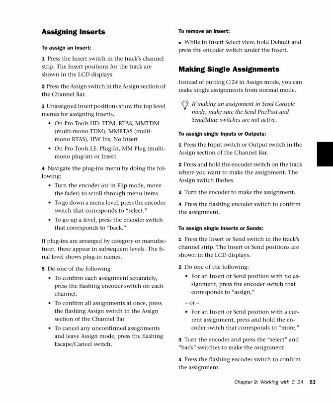
Assigning Inserts
To assign an Insert:
1 Press the Insert switch in the track’s channel strip. The Insert positions for the track are shown in the LCD displays.
2 Press the Assign switch in the Assign section of the Channel Bar.
3 Unassigned Insert positions show the top level menus for assigning inserts.
• On Pro Tools HD: TDM, RTAS, MMTDM (multi-mono TDM), MMRTAS (multi-mono RTAS), HW Ins, No Insert
• On Pro Tools LE: Plug-In, MM Plug (multi-mono plug-in) or Insert
4 Navigate the plug-ins menu by doing the fol-lowing:
• Turn the encoder (or in Flip mode, move the fader) to scroll through menu items.
• To go down a menu level, press the encoder switch that corresponds to “select.”
• To go up a level, press the encoder switch that corresponds to “back.”
If plug-ins are arranged by category or manufac-turer, these appear in subsequent levels. The fi-nal level shows plug-in names.
5 Do one of the following:
• To confirm each assignment separately, press the flashing encoder switch on each channel.
• To confirm all assignments at once, press the flashing Assign switch in the Assign section of the Channel Bar.
• To cancel any unconfirmed assignments and leave Assign mode, press the flashing Escape/Cancel switch.
To remove an insert:
While in Insert Select view, hold Default and press the encoder switch under the Insert.
Making Single Assignments
Instead of putting C|24 in Assign mode, you can make single assignments from normal mode.
To assign single Inputs or Outputs:
1 Press the Input switch or Output switch in the Assign section of the Channel Bar.
2 Press and hold the encoder switch on the track where you want to make the assignment. The Assign switch flashes.
3 Turn the encoder to make the assignment.
4 Press the flashing encoder switch to confirm the assignment.
To assign single Inserts or Sends:
1 Press the Insert or Send switch in the track’s channel strip. The Insert or Send positions are shown in the LCD displays.
2 Do one of the following:
• For an Insert or Send position with no as-signment, press the encoder switch that corresponds to “assign,”
– or –
• For an Insert or Send position with a cur-rent assignment, press and hold the en-coder switch that corresponds to “more.”
3 Turn the encoder and press the “select” and “back” switches to make the assignment.
4 Press the flashing encoder switch to confirm the assignment.
If making an assignment in Send Console mode, make sure the Send Pre/Post and Send/Mute switches are not active.
Chapter 9: Working with C|24 93
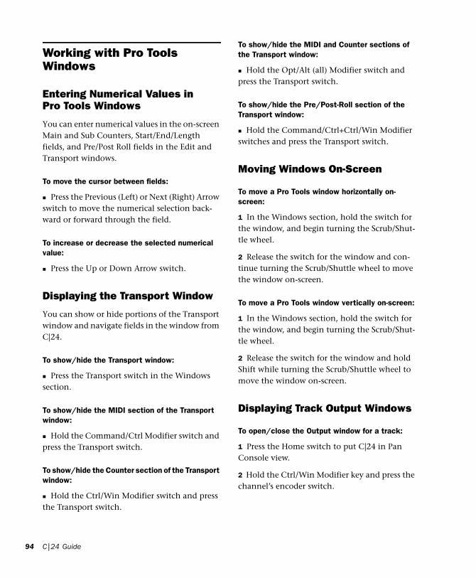
94
Working with Pro Tools Windows
Entering Numerical Values in Pro Tools Windows
You can enter numerical values in the on-screen Main and Sub Counters, Start/End/Length fields, and Pre/Post Roll fields in the Edit and Transport windows.
To move the cursor between fields:
Press the Previous (Left) or Next (Right) Arrow switch to move the numerical selection back-ward or forward through the field.
To increase or decrease the selected numerical value:
Press the Up or Down Arrow switch.
Displaying the Transport Window
You can show or hide portions of the Transport window and navigate fields in the window from C|24.
To show/hide the Transport window:
Press the Transport switch in the Windows section.
To show/hide the MIDI section of the Transport window:
Hold the Command/Ctrl Modifier switch and press the Transport switch.
To show/hide the Counter section of the Transport window:
Hold the Ctrl/Win Modifier switch and press the Transport switch.
C|24 Guide
To show/hide the MIDI and Counter sections of the Transport window:
Hold the Opt/Alt (all) Modifier switch and press the Transport switch.
To show/hide the Pre/Post-Roll section of the Transport window:
Hold the Command/Ctrl+Ctrl/Win Modifier switches and press the Transport switch.
Moving Windows On-Screen
To move a Pro Tools window horizontally on-screen:
1 In the Windows section, hold the switch for the window, and begin turning the Scrub/Shut-tle wheel.
2 Release the switch for the window and con-tinue turning the Scrub/Shuttle wheel to move the window on-screen.
To move a Pro Tools window vertically on-screen:
1 In the Windows section, hold the switch for the window, and begin turning the Scrub/Shut-tle wheel.
2 Release the switch for the window and hold Shift while turning the Scrub/Shuttle wheel to move the window on-screen.
Displaying Track Output Windows
To open/close the Output window for a track:
1 Press the Home switch to put C|24 in Pan Console view.
2 Hold the Ctrl/Win Modifier key and press the channel’s encoder switch.

To open/close Output windows for multiple tracks:
1 Press the Home switch to put C|24 in Pan Console view.
2 Hold the Ctrl/Win+Shift (add) Modifier switches and press the encoder switch on each channel whose window you want to open or close.
To close all open Output windows:
Hold the Opt/Alt (all) Modifier switch and press the Pan switch in the Windows section.
Displaying Send Windows
To open/close a Send window:
1 Display a Send position (A-J) across all tracks by pressing the corresponding Send switch in the Sends section of the Channel Bar.
2 Hold the Ctrl/Win Modifier key and press the encoder switch on the channel whose Send win-dow you want to open/close.
To open/close Send windows for multiple tracks:
1 Display a Send position (A-J) across all tracks by pressing the corresponding Send switch in the Sends section of the Channel Bar.
2 Hold the Ctrl/Win+Shift (add) Modifier switches and press the encoder switch on each channel whose window you want to open/close.
To close all open Send windows:
Hold the Opt/Alt (all) Modifier switch and press the Pan switch in the Windows section.
Displaying Plug-In Windows
To focus a plug-in on C|24 and open its window:
1 Press the Insert switch of the track whose plug-in you want to focus.
2 Press the encoder switch that corresponds to the Insert position for the plug-in.
The focused plug-in is indicated on C|24 by an asterisk below the Insert position.
To open or close a plug-in window on-screen for an Insert without focusing it on C|24:
1 Press the Insert switch in the track’s channel strip.
2 Hold the Ctrl/Win Modifier switch and press the encoder switch that corresponds to “more” for the plug-in.
Closing Floating Windows
To close or reopen all floating windows:
Hold the Command/Ctrl+Opt/Alt (all) Modi-fier switches and press the Plug-in switch or the Pan switch in the Windows section.
Chapter 9: Working with C|24 95

96
RecordingYou can select certain record modes, record en-able or record safe tracks for recording, arm the Pro Tools Transport, and initiate recording from C|24.
Enabling Pro Tools for Recording
To enable tracks for recording:
Press the Record Enable switch on each track you want to enable so that the switch flashes.
To toggle record-enabled status for all audio tracks in a session:
Press the Master Record Enable switch in the Global Controls section.
To toggle record-enabled status for all MIDI tracks in a session:
Hold the Opt/Alt (all) Modifier switch and press a Record Enable switch on a MIDI track.
To toggle the Input Monitor status on all tracks in a session (Pro Tools HD Only):
Hold Option/Alt (all) switch and press the In-put Monitor switch on a track.
To record safe a track:
Hold the Command/Ctrl Modifier switch and press the track’s Record Enable switch.
To arm the Pro Tools Transport for recording:
Press the Record switch in the Transport sec-tion so that it flashes.
C|24 Guide
Recording Audio
To record audio:
1 Record-enable the tracks where you want to record by pressing their Record Enable switches.
2 Arm Pro Tools for recording by pressing the Record switch in the Transport section.
3 Press the Play switch in the Transport section.
4 When you are finished, press the Stop switch in the Transport section.
Loop Recording Audio
To loop record audio:
1 Press the Link Edit and Timeline switch in the Tools & Functions section so that it is lit.
2 Press the Loop Record switch in the Transport Modes section so that it is lit.
3 To hear track material up to the start of the loop, enable pre-roll by pressing the Pre-Roll switch in the Transport Modes section.
4 Select the range in the Edit window that you want to loop.
5 Record-enable the tracks where you want to record by pressing their Record Enable switches.
6 Arm Pro Tools for recording by pressing the Record switch in the Transport section.
7 Press the Play switch in the Transport section.
8 When you are finished, press the Stop switch in the Transport section.

QuickPunch Recording
To punch in/out while audio recording with QuickPunch:
1 Press the QuickPunch switch in the Transport Modes section so that it is lit.
2 To hear track material up to the start of the punch, enable pre-roll by pressing the Pre-Roll switch in the Transport Modes section.
3 Place the playback cursor at a location before the punch-in point.
4 Record-enable the tracks where you want to record by pressing their Record Enable switches.
5 Arm Pro Tools for recording by pressing the Record switch in the Transport section.
6 Press the Play switch in the Transport section.
7 When you reach a punch-in point, press the Record switch in the Pro Tools Transport.
8 When you reach a punch-out point, press the Record switch in the Pro Tools Transport again.
Recording MIDI
To record MIDI:
1 Enable the click by pressing the Click switch in the Tools & Functions section so that it is lit.
2 Enable either Wait For Note or Countoff by pressing the corresponding switch in the Tools & Functions section so that it is lit.
3 Record enable the MIDI or Instrument tracks where you want to record by pressing their Record Enable switches.
4 Arm Pro Tools for recording by pressing the Record switch in the Transport section.
5 Press the Play switch in the Transport section.
6 When you are finished, press the Stop switch in the Transport section.
Loop Recording MIDI
To loop record MIDI:
1 Press the Link Edit and Timeline switch in the Tools & Functions section so that it is lit.
2 Press the Merge-Record switch in the Tools & Functions section so that it is lit.
3 Press the Loop Playback switch in the Trans-port Modes section so that it is lit.
4 Enable the click by pressing the Click switch in the Tools & Functions section so that it is lit.
5 Disable Wait For Note and Countoff by press-ing the corresponding switches in the Tools & Functions section so that they are unlit.
6 To hear track material up to the start of the loop, enable pre-roll by pressing the Pre-Roll switch in the Transport Modes section.
7 Select the range in the Edit window that you want to loop.
8 Record enable the MIDI or Instrument tracks where you want to record by pressing their Record Enable switches.
9 Arm Pro Tools for recording by pressing the Record switch in the Transport section.
10 Press the Play switch in the Transport sec-tion.
11 When you are finished, press the Stop switch in the Transport section.
Chapter 9: Working with C|24 97

98
Navigating and Selecting in the Edit Window
Zooming in the Edit Window
To zoom in horizontally on all tracks:
1 Press the Zoom switch.
2 Press the Right Arrow switch.
To zoom out horizontally on all tracks:
1 Press the Zoom switch.
2 Press the Left Arrow switch.
To zoom in vertically on all tracks:
1 Press the Zoom switch.
2 Press the Up Arrow switch.
To zoom out vertically on all tracks:
1 Press the Zoom switch.
2 Press the Down Arrow switch.
To horizontally zoom continuously in the Edit window:
Hold hold the Command/Ctrl Modifier switch and turn the Scrub/Shuttle wheel.
To vertically zoom continuously in the Edit window:
Hold the Command/Ctrl+Opt/Alt (all) Modi-fier switches and turn the Scrub/Shuttle wheel.
To zoom the current selection to fit the Edit window:
Hold the Opt/Alt (all) Modifier switch and press the Zoom switch.
C|24 Guide
To zoom out so that all regions are visible in the Edit window:
Double-press the Zoom switch.
Using Zoom Presets
To store a Zoom Preset:
1 Using either the Horizontal Zoom buttons or the Zoomer tool, set the zoom level that you want to store.
2 Hold the Command/Ctrl Modifier switch and press a Zoom Preset switch.
To recall a Zoom Preset:
Press the corresponding Zoom preset switch (1-5).
Paging and Scrolling in the Edit Window
To page horizontally in the Edit window:
1 Press the Navigate switch.
2 Hold the Command/Ctrl Modifier switch and press the Previous (Left) or Next (Right) Arrow switch.
To page vertically in the Edit window:
1 Press the Navigate switch.
2 Hold the Command/Ctrl Modifier switch and press the Up or Down Arrow switch.
To horizontally scroll the contents of the Edit window or Mix window:
1 Focus the window you want to scroll by click-ing in it or by pressing the corresponding win-dow key.
2 Hold the Opt/Alt (all) Modifier switch while turning the Scrub/Shuttle Wheel.

To vertically scroll the contents of the Edit window or Mix window:
1 Focus the window you want to scroll by click-ing in it or by pressing the corresponding win-dow key.
2 Hold the Shift (add) Modifier switch while turning the Scrub/Shuttle Wheel.
Selecting Audio
To move the cursor or Edit selection up or down one track:
1 Press the Navigate switch.
2 Press the Up or Down Arrow switch.
To extend an Edit selection up or down one track:
1 Press the Navigate switch.
2 Hold Shift and press the Up or Down Arrow switch.
To create selections with the Scrub/Shuttle wheel:
1 Locate the cursor in a track.
2 Do one of the following:
• Hold the Mark In switch and turn the Scrub/Shuttle wheel counter-clockwise to create or extend the selection to the left.
– or –
• Hold the Mark Out switch and turn the Scrub/Shuttle wheel clockwise to create or extend the selection to the right.
To scrub while adding to the front of a selection:
Hold the Ctrl/Win+Shift (add) Modifier switches while scrubbing the front of the selec-tion.
To scrub while adding to the end of a selection:
Hold the Ctrl/Win+Shift (add)+Opt/Alt (all) Modifier switches while scrubbing the end of the selection.
To scrub with fine resolution while adding to the front of a selection:
Hold the Ctrl/Win+Shift (add)+Com-mand/Ctrl Modifier switches while scrubbing the front of the selection.
To scrub with fine resolution while adding to the end of a selection:
Hold the Ctrl/Win+Shift (add)+Com-mand/Ctrl+Alt/Opt (all) Modifier switches while scrubbing the end of the selection.
Navigating with the Transport
The Transport switches correspond to the con-trols in the Pro Tools Transport window: Re-wind, Fast Forward, Stop, Play, and Record. The following transport functions are also available:
To latch the transport in Rewind:
Hold the Rewind switch and press Fast For-ward.
To latch the transport in Fast Forward:
Hold the Fast Forward switch and press Re-wind.
To return the playback cursor to the beginning of the session:
Press the RTZ/E switch.
To move the playback cursor to the end of the session:
Hold the Option/Alt (all) switch and press the RTZ/E switch.
Chapter 9: Working with C|24 99

100
Scrubbing Audio in the Edit Window
To scrub audio in Scrub mode:
1 While Pro Tools is stopped, press the Scrub switch.
2 Rotate the Scrub/Shuttle wheel clockwise to scrub audio forward, or counter-clockwise to scrub audio backward.
3 To exit, press the Scrub switch again.
To latch the Scrub/Shuttle wheel in scrub mode:
Press the Ctrl/Win Modifier switch momen-tarily (less than 1/2 second) while turning the Scrub/Shuttle wheel.
To scrub with fine resolution:
Hold the Command/Ctrl+Ctrl/Win Modifier switches while turning the Scrub/Shuttle Wheel.
Scrubbing Without Entering Scrub Mode
You can use the Scrub/Shuttle wheel to scrub while the transport is stopped or during play-back, without entering Scrub mode.
To scrub during playback:
1 Click in a track you want to scrub.
2 Hold the Ctrl/Win Modifier switch while turn-ing the Scrub/Shuttle wheel.
C|24 Guide
Scrubbing while Trimming a Region or Selection
(Pro Tools HD Only)
To use Trim/Scrub mode:
1 Navigate to a region or selection you want to trim.
2 Press the Trim switch.
3 Press the Scrub switch.
4 Rotate the Scrub/Shuttle wheel to move the cursor to the trim location.
5 To trim to the cursor location or to the begin-ning of the selection, press the Trim switch again.
Shuttling Audio in the Edit Window(Pro Tools HD Only)
To use Shuttle mode:
1 While Pro Tools is stopped, press the Shuttle switch.
2 Rotate the Scrub/Shuttle wheel clockwise to shuttle forward, or counter-clockwise to shuttle backward.
3 To exit, press the Shuttle switch again.
To trim to the end of a selection, hold the Opt/Alt (all) Modifier switch while pressing the Trim switch.

Auditioning Start and End Points of Selections
In Audition mode, you can listen to either the start or end of a selection, with or without pre-roll or post-roll.
To play audio starting at the pre-roll point up to the start of a selection:
1 Press the Audition switch so that it is lit.
2 Press the Pre-Roll switch.
To play audio starting at the selection start through the length of the post-roll amount:
1 Press the Audition switch so that it is lit.
2 Press the Mark In switch.
To play audio back-timed from the selection end by the pre-roll amount:
1 Press the Audition switch so that it is lit.
2 Press the Mark Out switch.
To play audio starting at the end of a selection through the post-roll amount:
1 Press the Audition switch so that it is lit.
2 Press the Post-Roll switch.
Editing
Selecting Edit Tools
You can select Edit tools by pressing the corre-sponding switches in the Tools & Functions sec-tion of C|24: Trim, Select, Grabber, Pencil, Smart Tool. The following Edit tool functions are also available:
To cycle through available versions of an Edit tool:
Press the corresponding Edit tool switch to cy-cle through the versions of the tool.
To select the Smart Tool:
Press the Smart switch.
– or –
Press any combination of the Trim, Select, and Grabber switches.
To lock and unlock Shuffle mode:
While in any Edit mode other than Shuffle mode, hold the Command/Ctrl Modifier switch and press the Shuffle switch.
Cutting and Pasting
To copy the current edit selection:
Press the Copy switch.
To paste a copied edit selection:
Press the Paste switch.
Chapter 9: Working with C|24 101

102
To copy the current plug-in settings:
1 Focus the plug-in whose settings you want to copy. (For information on focusing plug-ins, see “Focusing Plug-Ins on C|24” on page 78.)
2 Hold the Shift (add) Modifier switch and press the Copy switch.
To paste copied plug-in settings:
1 Focus the plug-in where you want to paste copied settings. (For information on focusing plug-ins, see “Focusing Plug-Ins on C|24” on page 78.)
2 Hold the Shift (add) Modifier switch and press the Paste switch.
Undoing Pro Tools Operations
To undo an action:
Press the Undo switch.
To redo an action:
Press the Redo switch.
Controlling Track Display on C|24
Banking and Nudging Tracks
To bank the position of tracks on C|24 forward or backward 24 channels at a time:
Press the lit Bank Left or Bank Right switch.
To nudge the position of tracks on C|24 one channel at a time:
1 Press the Nudge switch so that it is lit.
2 Press the Bank Left or the Bank Right switch.
C|24 Guide
To cascade the position of tracks on C|24 one channel at a time:
Hold any of the Nudge/Bank switches and turn the Scrub/Shuttle wheel clockwise or coun-terclockwise.
Transferring Controls to the Faders Using Flip Mode
To transfer controls from the rotary encoders to the touch-sensitive faders:
Press the Flip switch.
In Flip mode, faders can control channel pan, Send level, Send pan, or plug-in parameters, de-pending on the current view. See “Flip Modes” on page 86.
To return controls to Normal mode:
Press the flashing Flip switch.
Muting C|24 Fader Movement
You can temporarily turn off C|24 faders to pre-vent fader movement noise when monitoring a mix.
To toggle C|24 fader movement off and on:
1 Press the Soft Keys switch.
2 Press the encoder switch that corresponds to “Faders.”
3 Press the flashing Soft Keys switch to exit.

Mixing
Displaying Master Faders and VCA Masters
You can temporarily focus the Master Faders or VCA Master tracks (VCA Master tracks are avail-able in Pro Tools HD only) in your session in the right side of the C|24 faders.
To display Master Faders or VCA Masters:
Press the Masters switch repeatedly to cycle display of the available track types.
Working with Automation
Displaying the Automation Playlist for a Control
To display the automation playlist on-screen for a fader:
Hold the Command/Ctrl+Ctrl/Win Modifier switches and touch the fader.
To display the automation playlist on-screen for an encoder:
Hold the Command/Ctrl+Ctrl/Win Modifier switches and press the corresponding encoder switch.
Setting the Automation Mode of Channels
To cycle a channel forward through the automation modes:
Press the Automation Mode switch on the channel.
To cycle a channel backward through the automation modes:
Hold the Shift (add) Modifier switch and press the Automation Mode switch on the channel.
To toggle a channel in and out of Trim mode (Pro Tools HD Only):
Hold the Trim switch in the Automation Modes section and press the channel’s Select or Auto switch.
To set the automation mode of one or more channels:
1 Hold an Automation Mode switch or switches (Write, Touch, Latch, Touch+Latch, Trim, Read, or Off).
2 Press the Select switch or Auto switch on the channels whose automation mode you want to set.
To set the automation mode of one or more selected channels:
1 Press the Do To Selected switch.
2 Press the Select switches on the channels whose automation mode you want to set.
3 Press an Automation Mode switch or switches (Write, Touch, Latch, Touch+Latch, Trim, Read, or Off).
Chapter 9: Working with C|24 103

104
To set the automation mode of all channels:
1 Press the Do To All switch.
2 Press an Automation Mode switch or switches (Write, Touch, Latch, Touch+Latch, Trim, Read, or Off).
Suspending Automation
To suspend automation for all channels:
Press the Suspend switch in the Automation Enable section.
To toggle the write enable status of an automation type across all channels:
Press the switch for the corresponding auto-mation type (Volume, Pan, Mute, Send Level, Send Pan, Send Mute, or Plug-In) in the Automa-tion Enable section.
Enabling Plug-in Automation
To toggle the automation enable status of plug-in parameters:
1 Press the Insert switch in the track’s channel strip.
2 For the plug-in you want to display, press the encoder switch that corresponds to “more.”
3 Press the Select/Auto switch in the Switch Functions section so that it is lit.
4 Press the encoder switches for the parameters whose automation enable status you want to change. The encoder switch lights to indicate that a parameter is enabled.
5 When you are finished, press the Select/Auto switch in the Switch Functions section so that it is unlit.
C|24 Guide
To toggle the automation bypass status of a plug-in:
1 Press the Insert switch in the track’s channel strip.
2 For the plug-in you want to display, press the encoder switch that corresponds to “more.”
3 Press the Select/Auto switch in the Switch Functions section so that it is lit.
4 Press the Master Bypass switch in the Inserts section of the Channel Bar.
5 When you are finished, press the Select/Auto switch in the Switch Functions section so that it is unlit.
Punching Out of Plug-in Automation During an Automation Pass
To punch out of writing automation for a plug-in parameter during an automation pass:
1 Press the Insert switch in the track’s channel strip.
2 For the plug-in you want to display, press the encoder switch that corresponds to “more.”
3 Press the Select/Auto switch in the Switch Functions section so that it is lit.
4 Press Play to begin the automation pass.
5 During the automation pass, press a flashing encoder switch to punch the corresponding pa-rameter out of automation write mode.
6 When you are finished, press the Select/Auto switch in the Switch Functions section so that it is unlit.

Previewing Automation
(Pro Tools HD Only)
To preview a new automation value for a control:
1 Enable the track for automation by cycling its Automation Mode switch to enable Touch, Latch, or Touch/Latch mode.
2 Enable the automation type by pressing its switch in the Automation Enable section.
3 Hold the Command/Ctrl Modifier switch and press the Off switch in the Global Automation Modes section. The Off switch flashes to indi-cate Preview mode.
4 Isolate a control by moving it.
5 Start playback and adjust the isolated control to audition the new automation value.
To suspend Preview mode:
Hold the Command/Ctrl Modifier switch and press the Read switch in the Global Automation Modes section.
To punch a preview value to the automation playlist:
Hold the Command/Ctrl Modifier switch and press the flashing Off switch in the Global Auto-mation Modes section.
Capturing Automation
(Pro Tools HD Only)
To capture automation values:
1 Enable the tracks whose automation values you want to capture by cycling their Automa-tion Mode switches to a write-enabled state (Write, Touch, Touch/Latch, or Latch).
2 Enable all of the automation types you want to capture by pressing their switches in the Au-tomation Enable section.
3 Start playback.
4 When you reach a location where you want to capture the current automation states, hold the Command/Ctrl Modifier switch and press the Touch switch in the Global Automation Modes section.
To punch captured automation values:
1 Move to a location where you want to apply the captured automation states.
2 Hold the Command/Ctrl+Ctrl/Win Modifier switches and press the Touch switch in the Glo-bal Automation Modes section.
AutoMatching Controls(Pro Tools HD Only)
To AutoMatch all currently writing controls:
1 Make sure the automation types you want to AutoMatch are write-enabled.
2 Start playback.
3 When you reach a point in the session where you want to return controls to their previously written values, hold the Command/Ctrl Modi-fier switch and press the Latch switch in the Glo-bal Automation section.
Chapter 9: Working with C|24 105
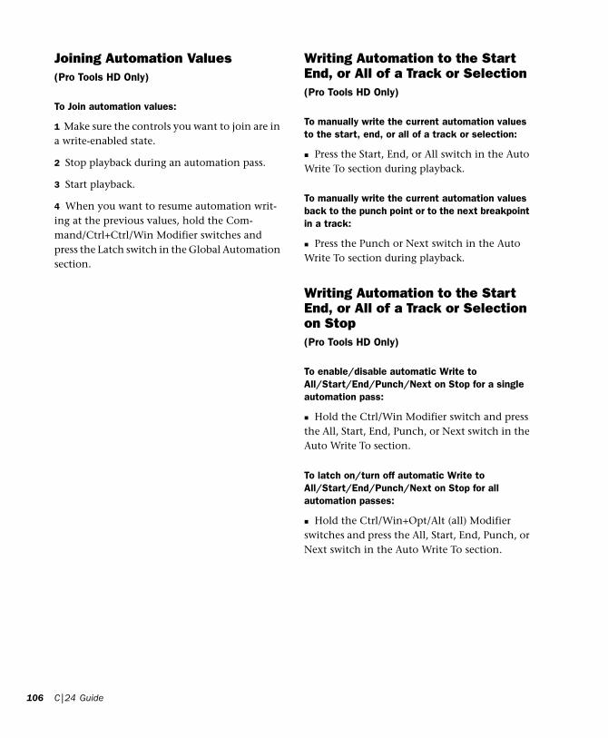
106
Joining Automation Values (Pro Tools HD Only)
To Join automation values:
1 Make sure the controls you want to join are in a write-enabled state.
2 Stop playback during an automation pass.
3 Start playback.
4 When you want to resume automation writ-ing at the previous values, hold the Com-mand/Ctrl+Ctrl/Win Modifier switches and press the Latch switch in the Global Automation section.
C|24 Guide
Writing Automation to the Start End, or All of a Track or Selection(Pro Tools HD Only)
To manually write the current automation values to the start, end, or all of a track or selection:
Press the Start, End, or All switch in the Auto Write To section during playback.
To manually write the current automation values back to the punch point or to the next breakpoint in a track:
Press the Punch or Next switch in the Auto Write To section during playback.
Writing Automation to the Start End, or All of a Track or Selection on Stop(Pro Tools HD Only)
To enable/disable automatic Write to All/Start/End/Punch/Next on Stop for a single automation pass:
Hold the Ctrl/Win Modifier switch and press the All, Start, End, Punch, or Next switch in the Auto Write To section.
To latch on/turn off automatic Write to All/Start/End/Punch/Next on Stop for all automation passes:
Hold the Ctrl/Win+Opt/Alt (all) Modifier switches and press the All, Start, End, Punch, or Next switch in the Auto Write To section.

Appendix A: C|24 Connector Pinouts
Female DB-25 ConnectorsAll C|24 DB-25 connector pinouts conform to the pin numbering scheme shown below.
Preamps 1–8
Mic In 1–8
DB-25 Connector (user view)
Mic Preamp Inputs 1–8
Channel Hot (+) Cold (–) Ground (shield)
1 Preamp Mic In 1
24 12 25
2 Preamp Mic In 2
10 23 11
3 Preamp Mic In 3
21 9 22
4 Preamp Mic In 4
7 20 8
113
1425
Line/DI In 1–8
5 Preamp Mic In 5
18 6 19
6 Preamp Mic In 6
4 17 5
7 Preamp Mic In 7
15 3 16
8 Preamp Mic In 8
1 14 2
Mic Preamp Inputs 1–8
Channel Hot (+) Cold (–) Ground (shield)
1 Preamp Line In 1
24 12 25
2 Preamp Line In 2
10 23 11
3 Preamp Line In 3
21 9 22
4 Preamp Line In 4
7 20 8
5 Preamp Line In 5
18 6 19
6 Preamp Line In 6
4 17 5
7 Preamp Line In 7
15 3 16
8 Preamp Line In 8
1 14 2
Mic Preamp Inputs 1–8
Channel Hot (+) Cold (–) Ground (shield)
Appendix A: C|24 Connector Pinouts 107

108
Line Out 1–8
Preamps 9–16
Mic In 9–16
Preamp Line Outputs 1–8
Channel Hot (+) Cold (–) Ground (shield)
1 Preamp Line Out 1
24 12 25
2 Preamp Line Out 2
10 23 11
3 Preamp Line Out 3
21 9 22
4 Preamp Line Out 4
7 20 8
5 Preamp Line Out 5
18 6 19
6 Preamp Line Out 6
4 17 5
7 Preamp Line Out 7
15 3 16
8 Preamp Line Out 8
1 14 2
Mic Preamp Inputs 9–16
Channel Hot (+) Cold (–) Ground (shield)
1 Preamp Mic In 9
24 12 25
2 Preamp Mic In 10
10 23 11
3 Preamp Mic In 11
21 9 22
4 Preamp Mic In 12
7 20 8
C|24 Guide
Line/DI In 9–16
5 Preamp Mic In 13
18 6 19
6 Preamp Mic In 14
4 17 5
7 Preamp Mic In 15
15 3 16
8 Preamp Mic In 16
1 14 2
Mic Preamp Inputs 9–16
Channel Hot (+) Cold (–) Ground (shield)
1 Preamp Line In 9
24 12 25
2 Preamp Line In 10
10 23 11
3 Preamp Line In 11
21 9 22
4 Preamp Line In 12
7 20 8
5 Preamp Line In 13
18 6 19
6 Preamp Line In 14
4 17 5
7 Preamp Line In 15
15 3 16
8 Preamp Line In 16
1 14 2
Mic Preamp Inputs 9–16
Channel Hot (+) Cold (–) Ground (shield)

Line Out 9–16
Preamp Line Outputs 9–16
Channel Hot (+) Cold (–) Ground (shield)
1 Preamp Line Out 9
24 12 25
2 Preamp Line Out
10
10 23 11
3 Preamp Line Out
11
21 9 22
4 Preamp Line Out
12
7 20 8
5 Preamp Line Out
13
18 6 19
6 Preamp Line Out
14
4 17 5
7 Preamp Line Out
15
15 3 16
8 Preamp Line Out
16
1 14 2
Submixer 1–8 ST
Submix In 1–4 (ST)
Submixer Stereo Inputs 1–4
Channel Hot (+) Cold (–) Ground (shield)
1 Submixer In 1 Left
24 12 25
2 Submixer In 1 Right
10 23 11
3 Submixer In 2 Left
21 9 22
4 Submixer In 2 Right
7 20 8
5 Submixer In 3 Left
18 6 19
6 Submixer In 3 Right
4 17 5
7 Submixer In 4 Left
15 3 16
8 Submixer In 4 Right
1 14 2
Appendix A: C|24 Connector Pinouts 109

110
Submix In 5–8 (ST)
Submixer Stereo Inputs 5–8
Channel Hot (+) Cold (–) Ground (shield)
1 Submixer In 5 Left
24 12 25
2 Submixer In 5 Right
10 23 11
3 Submixer In 6 Left
21 9 22
4 Submixer In 6 Right
7 20 8
5 Submixer In 7 Left
18 6 19
6 Submixer In 7 Right
4 17 5
7 Submixer In 8 Left
15 3 16
8 Submixer In 8 Right
1 14 2
C|24 Guide
Monitor Section
Pro Tools In
Pt 1–6 + Cue 1–2
Pro Tools and Cue Inputs
Channel Hot (+) Cold (–) Ground (shield)
1 Main In Left
24 12 25
2 Main In Center
10 23 11
3 Main In Right
21 9 22
4 Main In Left
Surround
7 20 8
5 Main In Right
Surround
18 6 19
6 Main In LFE
4 17 5
7 Cue In Left
15 3 16
8 Cue In Right
1 14 2

Surround In
Alt Sur 1–6
Alternate Surround Inputs (1–6)
Channel Hot (+) Cold (–) Ground (shield)
1 Alt Surround
In Left
24 12 25
2 Alt Surround In Center
10 23 11
3 Alt Surround In Right
21 9 22
4 Alt Surround
In Left Surround
7 20 8
5 Alt Surround In Right
Surround
18 6 19
6 Alt Input LFE
4 17 5
7 (unused)
15 3 16
8 (unused)
1 14 2
Ext Stereo In
Ext St 1 + St 2
External Stereo Inputs 1 and 2
Channel Hot (+) Cold (–)Ground (shield)
1 Stereo In 1 Left
24 12 25
1 Stereo In 1 Right
10 23 11
3 Stereo In 2 Left
21 9 22
4 Stereo In 2 Right
7 20 8
5 (unused) 18 6 19
6 (unused) 4 17 5
7 (unused) 15 3 16
8 (unused) 1 14 2
Appendix A: C|24 Connector Pinouts 111

112
Control Room Out
5.1 Mon Out L:1 R:3
Main and Alternate Outputs
Channel Hot (+) Cold (–)Ground (shield)
1 Main Out Left 24 12 25
2 Main Out Center
10 23 11
3 Main Out Right
21 9 22
4 Main Out Left Surround
7 20 8
5 Main Out Right Surround
18 6 19
6 Main Out LFE 4 17 5
7 Alt Out Left 15 3 16
8 Alt Out Right 1 14 2
C|24 Guide
Cue Outputs
Cues + SLS + TB
XLR and TRS Connectors
XLR Mic Inputs
TRS 1/4-Inch Inputs and Outputs
Cue and Studio LS Monitor Outputs
Channel Hot (+) Cold (–)Ground (shield)
1 Cue Out Left
24 12 25
2 Cue Out Right
10 23 11
3 Studio LS Out Left
21 9 22
4 Studio LS Out Right
7 20 8
5 Talkback Slate Out
18 6 19
6 (unused) 4 17 5
7 (unused) 15 3 16
8 (unused) 1 14 2
Channel Hot (+) Cold (–)Ground (shield)
all XLR Mic Inputs(female)
2 3 1
Channel Hot (+) Cold (–)Ground (shield)
all TRS 1/4-inch I/O
Tip Ring Sleeve

Appendix B: Utility Mode
C|24 Utility mode lets you run diagnostic tests, set hardware preferences, view system informa-tion, and reset system settings.
Entering and Exiting Utility ModeYou can enter Utility mode at any time to change C|24 settings.
To enter Utility mode:
Press the Utility switch.
The top level Utility options are shown in the LCD displays. The Utility switch flashes to indi-cate Utility mode is active.
To exit Utility mode:
Press the encoder switch that corresponds to “Exit.”
– or –
Press the flashing Utility switch.
If you are displaying a Utility mode page and press the Utility switch to exit before saving, any changes will be lost.
TestsThe C|24 Test pages let you test the mechanical and electronic components of the unit.
To display the Test pages:
1 Press the Utility switch.
2 Press the encoder switch that corresponds to “Tests.”
To enter a Test page:
Press the encoder switch that corresponds to the test name.
To exit the Test pages:
Press the encoder switch that corresponds to “Exit.”
Ethernet Test Page
There are two test levels for Ethernet communi-cation on C|24: Internal and External.
Each test sends data packets through the C|24 Ethernet system. The “Sent” and “Received” val-ues for each test show the number of packets sent and received in the test, and the “Errors” and “Retries” fields show percentage error in the transmission and receiving process. An error rate of 1 percent or less generally indicates ac-ceptable performance. (In normal operation, er-rors are retried and no data loss occurs.)
Appendix B: Utility Mode 113

114
Internal
The Internal test verifies the first stage of Ether-net communication by sending data packets through the unit’s Ethernet link chip.
To perform the Internal Ethernet test:
From the Ethernet Test page, press the en-coder switch that corresponds to “Internal.”
To restart the “Sent” and “Received” packet counts:
Press the encoder switch that corresponds to “Restart Counts.”
To exit the Internal Ethernet test:
Press the encoder switch that corresponds to “Exit.”
External
The External test verifies the second stage of Ethernet communication by sending data pack-ets out of the C|24 Ethernet port and back into the unit using an Ethernet loopback connector (included with C|24).
To perform the External Ethernet test:
1 If Pro Tools is running, quit Pro Tools.
2 Disconnect C|24 from the Ethernet network.
3 Plug the Ethernet Loopback connector into the C|24 Ethernet port.
4 From the Ethernet Test page, press the en-coder switch that corresponds to “External.
To restart the “Sent” and “Received” packet counts:
Press the encoder switch that corresponds to “Restart Counts.”
C|24 Guide
To exit the External Ethernet test:
Press the encoder switch that corresponds to “Exit.”
LED Test Page
The LED tests let you test all red, yellow, or green LEDs on C|24 individually.
To test the LEDs:
From the LED Test page, press the encoder switch that corresponds to any of the following to test all LEDs of the specified color:
• Red LEDs
• Yellow LEDs
• Green LEDs
To exit an LED test:
Press the encoder switch that corresponds to “Exit.”
Vegas Mode
Vegas mode randomly lights every switch, meter, and display on the unit, and runs the fad-ers in a sine wave pattern.
To enter Vegas mode:
Press the encoder switch that corresponds to “Vegas Mode.”
To vary the rate of LED blinking and fader motion:
Turn the Scrub/Shuttle wheel or any rotary encoder.
To exit Vegas mode:
Press any switch on the unit.

Display Test Page
The Display tests let you test the LCD displays and the Main Counter on C|24.
To test the LCD displays:
From the Display Test page, press the encoder switch that corresponds to one of the following:
• ASCII Set: Shows the entire ASCII character set at once.
• ASCII Step: Cycles through the ASCII char-acter set on each LCD segment.
To test the Main Counter:
From the Display Test page, press the encoder switch that corresponds to “Timecode.”
The Main Counter cycles through 0-9 and the Time Display Format Indicators light.
To exit a Display test:
Press the encoder switch that corresponds to “Exit.”
Fader Test Page
The Fader tests let you test and recalibrate the C}24 faders.
To test the faders:
From the Fader Test page, press the encoder switch that corresponds to any of the following:
Step Faders move together, in stepped fashion, to positions that are adjustable with the Scrub/Shuttle wheel. Fader position values are shown in the LCD displays (0-1023).
Cycle Faders move together, from the bottom to top, in a continuous cycle, at a speed that is ad-justable with the Scrub/Shuttle wheel. Fader po-sition values are shown in the LCD displays (0-1023).
Group Faders can be moved to test group re-sponse. Fader position values are shown in the LCD displays (0-1023). This test shows which faders are currently being touched by displaying the letter “T” in the LCD displays above the fad-ers.
Touch Each fader can be touched to show touch sensitivity. The LCD displays show the fre-quency that the fader is currently recognizing. This test shows which faders are currently being touched by displaying the letter “T” in the LCD displays above the faders.
To exit a Fader test:
Press the encoder switch that corresponds to “Exit.”
Recalibrating the Faders
The Recalibrate command recalibrates the touch sensitivity and position of all faders to factory specifications.
To recalibrate the faders:
From the Fader Test page, press the encoder switch that corresponds to “Recalibrate.”
Rotary Test Page
The Rotary test lets you test the C}24 rotary en-coders that have LED rings (the 24 channel ro-tary encoders and the Control Room encoder).
The Rotary test shows two values:
• Delta: Shows the direction and speed an in-dividual encoder is being turned.
• Cumulative: Shows the number of steps that all of the encoders have been turned during the text.
To test the rotary encoders:
From the Rotary Test page, turn any encoder.
Appendix B: Utility Mode 115

116
Switch Test Page
The Switch test lets you test each switch on C|24 individually.
To test any switch:
From the Switch Test page, press the switch you want to test.
The switch LED lights as long as it is held, and the LCD displays show the location information for the switch.
To exit the Switch test:
Press the encoder switch that corresponds to “Exit.”
PreferencesThe C|24 Preferences pages let you set prefer-ences for Talkback microphone operation, mic/line/DI preamplifier clip indication, and footswitch operation.
Talkback
External Talkback Microphone
You can choose to use an external Talkback mi-crophone instead of the built-in Talkback micro-phone in the C|24 Meter Bridge.
When the external Talkback microphone is en-abled, the built-in Talkback microphone is auto-matically disabled.
C|24 Guide
To enable the external Talkback microphone:
1 Press the Utility switch.
2 Press the encoder switch that corresponds to “Preferences.”
3 Press the encoder switch that corresponds to “Talkback.”
4 Press the encoder switch that corresponds to “Ext TB Mic” to toggle the external talkback in-put On or Off.
5 When you are finished, press the encoder switch that corresponds to “Save.”
6 Press the Exit switch to exit Utility mode.
Talkback Latching
You can set Talkback to latch on when the Talk-back switch is double-pressed.
When Talkback latching is Off, the Talkback switch follows momentary behavior only.
When Talkback latching is On, the Talkback switch follows momentary behavior when held, and latches on and off when double-pressed. When latched on, the Talkback switch flashes.
To toggle Talkback latching:
1 Press the Utility switch.
2 Press the encoder switch that corresponds to “Preferences.”
3 Press the encoder switch that corresponds to “Talkback.”
4 Press the encoder switch that corresponds to “TB Latching” to toggle Talkback latching capa-bility On or Off.
5 When you are finished, press the encoder switch that corresponds to “Save.”
6 Press the Exit switch to exit Utility mode.

Mic Pre Clip Hold
You can set the Clip Hold time for the C|24 built-in mic/line/DI preamplifiers.
To set the Clip Hold time:
1 Press the Utility switch.
2 Press the encoder switch that corresponds to “Preferences.”
3 Press the encoder switch that corresponds to “Analog.”
4 Press the encoder switch that corresponds to one of the following:
• No Hold
• 3 Sec Hold
• Infinite Hold
5 When you are finished, press the encoder switch that corresponds to “Save.”
6 Press the Exit switch to exit Utility mode.
Footswitch Function and Polarity
You can set the function and polarity for the two Footswitch connectors on C|24.
To set Footswitch function:
1 Press the Utility switch.
2 Press the encoder switch that corresponds to “Preferences.”
3 Press the encoder switch that corresponds to “Footswitch.”
4 For each Footswitch (A and B), press the en-coder switch that corresponds to any of the following:
• Play: Starts and stops the Pro Tools Trans-port.
• Record: Arms the Transport for recording or punches in and out of Record.
• Talkback: Toggles Talkback On and Off.
5 When you are finished, press the encoder switch that corresponds to “Save.”
6 Press the Exit switch to exit Utility mode.
To set Footswitch polarity:
1 Press the Utility switch.
2 Press the encoder switch that corresponds to “Preferences.”
3 Press the encoder switch that corresponds to “Footswitch.”
4 Press the encoder switch under “FS A Polarity” (Footswitch A) or “FS B Polarity” (Footswitch B) to toggle polarity between “Normal” and “In-verted.”
5 When you are finished, press the encoder switch that corresponds to “Save.”
6 Press the Exit switch to exit Utility mode.
Appendix B: Utility Mode 117

118
SystemThe C|24 System pages let you view component firmware versions and Ethernet information, name the C|24 unit, and reset the C|24 to its fac-tory settings.
Firmware Versions
This page shows the Comm board and Motor Control board firmware versions.
To view the current firmware versions for C|24 components:
1 Press the Utility switch.
2 Press the encoder switch that corresponds to “System.”
3 Hold the encoder switch that corresponds to “FW Versions.”
4 When you are finished, press the encoder switch that corresponds to “Exit.”
Ethernet
This page shows the following information for the C|24:
• Unit Name (as named on the Unit Name page)
• Unit Number: Digidesign serial number for the unit
• Frame Type: Ethernet packet type used by Digidesign for control surface communica-tion
• Ethernet ID: Ethernet address (Machine Address Code) for the unit
C|24 Guide
To view the Ethernet information for C|24:
1 Press the Utility switch.
2 Press the encoder switch that corresponds to “System.”
3 Hold the encoder switch that corresponds to “Ethernet.”
4 When you are finished, press the encoder switch that corresponds to “Exit.”
Unit Name
This page lets you view, change, or reset the C|24 Unit Name.
To name C|24 from the unit:
1 Press the Utility switch.
2 Press the encoder switch that corresponds to “System.”
3 Press the encoder switch that corresponds to “Unit Name. “
The unit name appears in the LCD displays. The first character of the name flashes to indicate text entry.
4 To change the selected character, turn the en-coder under “Character.”
5 To move forward and backward in the text field, turn the encoder under “Position.”
6 When you are finished, press the encoder switch that corresponds to “Save.”

To set the C|24 name to the default:
1 Press the Utility switch.
2 Press the encoder switch that corresponds to “System.”
3 Press the encoder switch that corresponds to “Unit Name. “
4 Press the encoder switch that corresponds to “Default.”
5 Press the encoder switch that corresponds to “Save.”
Resetting User Preferences
This page lets you reset C|24 Footswitch prefer-ences, Talkback preferences and Clip Hold time for the built-in mic/line/DI preamplifiers to their default values.
To reset the C|24 user preferences:
1 Press the Utility switch.
2 Press the encoder switch that corresponds to “System.”
3 Hold the encoder switch that corresponds to “Reset User Prefs.”
4 Do one of the following:
• To confirm the reset, press the encoder switch that corresponds to “OK.”
– or –
• To cancel the reset, press the encoder switch that corresponds to “Cancel.”
5 When you are finished, press the encoder switch that corresponds to “Exit.”
Resetting Analog Signal Routing
This page lets you reset C|24 monitor and cue source selections, and Monitor solo, phantom power, Mic/Line and HPF settings to their de-fault values.
To reset monitor signal routing:
1 Press the Utility switch.
2 Press the encoder switch that corresponds to “System.”
3 Hold the encoder switch that corresponds to “Reset Analog Routes.”
4 Do one of the following:
• To confirm the reset, press the encoder switch that corresponds to “OK.”
– or –
• To cancel the reset, press the encoder switch that corresponds to “Cancel.”
5 When you are finished, press the encoder switch that corresponds to “Exit.”
Appendix B: Utility Mode 119

120
Resetting Monitor Gain Settings
This page lets you reset gain and trim levels in the C|24 monitor section (set with the Control Room rotary encoder) to their default values.
To reset monitor gain levels and trim offsets:
1 Press the Utility switch.
2 Press the encoder switch that corresponds to “System.”
3 Hold the encoder switch that corresponds to “Reset Monitor Gains.”
4 Do one of the following:
• To confirm the reset, press the encoder switch that corresponds to “OK.”
– or –
• To cancel the reset, press the encoder switch that corresponds to “Cancel.”
5 When you are finished, press the encoder switch that corresponds to “Exit.”
C|24 Guide
Auto TalkbackAuto Talkback is a setting that automatically turns on the Talkback and Listen microphones when the Pro Tools Transport is stopped, and turns the Talkback and Listen microphones off when the Pro Tools Transport is running.
To activate Auto Talkback:
1 Press the Utility switch.
2 Press the encoder switch that corresponds to “Auto Talkback” to toggle the Auto Talk option On and Off.
3 When you are finished, press the encoder switch that corresponds to “Exit.”

Symbols+48V (phantom power) 67
Numerics5.1 output mode (Monitor section) 62
AActions (Soft Keys) 48AFL/PFL 65After Fader Listen mode 65All Notes Off switch 51All switch (automation) 44Alt Monitor switch 63Alternate Function switch 50, 51Alternate Surround Input switch 64Arrow switches 56, 89, 90, 94, 98, 99Assign mode 87Assign section (Channel Bar) 46Assign switch 46, 91, 92, 93assigning paths 91, 92, 93audio
editing 101recording 96
Audition mode 101Audition switch 54, 101Auto Talkback 18, 120automation
Allow Latch Prime in Stop 48Auto Join 48AutoMatching 105capturing 48, 105coalescing 48displaying 103joining 106plug-ins 104preferences 48previewing 48, 105
punching 104Safe mode 45setting modes 103suspending 43Write controls 106
Automation Enable switches 43Mute 43Pan 43Plug-in 43Send Level 43Send Mute 43Send Pan 43Suspend 43Volume 43
Automation Mode switches (channel strips) 42, 103
Automation Mode switches (global) 42Latch 43Off 43Read 43Touch 43Trim 43Write 43
automation preferences (Soft Keys) 48Automation switch (Window switches) 52Automation Write To switches 44
All 44End 44Next 44Punch 44Start 44
BBank switches 57Big Counter switch (Window switches) 52bypassing
inserts 41plug-ins 42, 79sends 41
index
Index 121

122
CC|24 unit
declaring 17dimensions 5naming 17
Center Percentage switch 47Channel Bar 10, 45Channel Select switches 38Channel views 71, 73Channel Window Display (console preference) 48Clear Clip switch 60Click switch 51, 97clip hold time 117clip indicators (preamplifier section) 18, 67, 117Command/Ctrl switch 44Compare switch 45configuring the C|24 16connections
computer 15Control Room Monitor section 11, 23, 24, 109Ethernet 7, 15, 17footswitches 11headphones 26line submixer 22, 107, 112Listen microphone 11, 26power 15preamplifiers 11, 19, 21, 107, 108, 112submixer 11Talkback microphone (external) 11, 26
console preferences 47Channel Window Display 48Select Switch Latch Mode 47Touch Display of Parameter Values 47Track Display 47Two-Knob Panning 48
Console views 71Control Room Monitor section 10
Alt Monitor switch 63Alternate outputs 24, 66Alternate Surround input 64connections 11, 23, 24, 109Cue level 63Dim controls 64, 66Headphone cue monitoring 63Headphone level 63input selectors 64line submixer output controls 65, 68Listen Mic level 63
C|24 Guide
Main input 64Main Output switches 62Main outputs 24, 65Mono function 64, 66Mute 64output controls 63, 64Output Mode controls 62resetting 119, 120Solo mode 62Stereo inputs 64Studio LS level 63Sum 65Talkback level 63
Copy switch 50, 101Count Off switch 51, 97Counter switch 60Create switch (Groups) 53Ctrl/Win switch 44Cue level controls 63Cue outputs 25
Ddeclaring the C|24 17Default switch 52, 90, 93Delete switch (Groups) 53DI preamplifiers 67Dim switch 64Display Mode switch 40Divergence switch 46Do To All switch 52, 91Do To Selected switch 52, 91Dynamic Transport switch 55Dynamics Bypass switch 42Dynamics switches (channel strips) 41
EEdit Mode switches 49
Grid 49Shuffle 49Slip 49Spot 49
Edit switch (Window switches) 51Edit switches 50
Copy 50Paste 50
Edit Tool switches 50Grabber 51Pencil 51Select 50Smart 51Trim 50
Edit window 94Enable switch (Groups) 53encoder switch functions 39End switch (automation) 44Enter switch 56EQ Bypass switch 42EQ switches (channel strips) 41Escape/Cancel switch 46, 56Ethernet 7, 11, 17, 113, 118Expanded Mic Pre view 82Expanded Pan view 75Expanded Send view 76
FFader Display modes 86faders 37
muting 102recalibrating 115
File/Utility switchesEnter 56Escape/Cancel 56Redo 55Save 56Undo 55Utility 55
firmware 16, 118F-J switch 49Flip modes 86Flip switch 58, 102Focus switch 50footswitch settings 117footswitches 11, 18, 117From Cue switch 63Front-Rear switch 46
GGlobal Controls
Default 52Do To All 52Do To Selected 52Input Monitor 53Master Record Enable 53Plug-in Safe 53Solo Clear 53Velocity Sensitive 53
Go To End switch 54Grabber switch (Edit tools) 51Grid switch 49Groups switches
Create 53Delete 53Enable 53Modify 53Suspend 53
Groups view 83
Hheadphones 26
cue monitoring 63level knob 63
Home switch 50, 94Home/Pan Flip mode 86
II/O Setup (Pro Tools) 65Input Level knobs (line submixer) 68Input Level knobs (preamplifier section) 67Input Monitor switch (global) 53Input Monitor switches (channel strips) 38, 96Input switch (Channel Bar) 46, 91, 93Insert Bypass switch 41Insert Select view 78Insert switches (channel strips) 40, 93, 95Insert/Parameter switch (Channel Bar) 45Inserts section (Channel Bar) 45
JJoin (automation) 48
Kkeyboard modifiers 44
Index 123
124
LL(C)R switch 46L/R switch 47Latch switch (automation) 43LCRS output mode (Monitor section) 62LFE switch 47line preamplifiers 67line submixer 10, 22, 68Link Edit and Timeline switch 51, 96, 97Link Track and Edit Selection switch 51Listen Mic level controls 63loop playback 97Loop Playback switch 55Loop Record switch 55, 96loop recording 96, 97
MMain Counter 59Main switch 64Main to Cue switch 63Mark In switch 55, 99, 101Mark Out switch 55, 99, 101Master Bypass switch 45Master Fader mode 86Master Faders 103Master Record Enable switch 53, 96Masters switch 58, 86, 103Memory Location view 85Memory Locations switch (Window switches) 52Merge-Record switch 51, 97meters 10, 59, 60Meters Post switch 60Mic Pre Flip mode 87Mic Pre switch 50Mic Pre view 82microphone preamplifiers 67MIDI
editing 101loop recording 97recording 97
MIDI Command switches 51MIDI controls
All Notes Off 51Click 51Count Off 51
C|24 Guide
Merge-Record 51Wait For Note 51
MIDI Operations switch (Window switches) 52MIDI Real-Time Properties 52Mix switch (Window switches) 51modifier switches 44
Command/Ctrl 44Ctrl/Win 44Opt/Alt (all) 44Shift (add) 44
Modify switch (Groups) 53Monitor section 61Mono switch 64Mute switch (automation) 43Mute switch (Monitor section) 64Mute switches (channel strips) 37
Nnaming the C|24 17, 118Navigate switch 56, 98, 99Next switch (automation) 44Normal mode 86Nudge switch 57, 102
OOff switch (automation) 43Online switch 54Opt/Alt (all) switch 44Output Level knob (line submixer) 68Output Mode switch 62Output switch 46, 91, 93Output windows 94
PPan Console view 71Pan section (Channel Bar) 46Pan switch (automation) 43Pan switch (Window switches) 52, 95Pan/Send Channel view 73Parameter view 80Paste switch 50, 101Pencil switch (Edit tools) 51phantom power switches (preamplifier section) 67Plug-in Flip mode 87Plug-in Safe switch 53

Plug-in switch (automation) 43Plug-in switch (Window switches) 52, 95plug-ins
bypassing 79closing 95focusing 78opening 79, 95
Post-Roll switch 54, 101Pre Fader Listen mode 65Pre/Post switch (encoder switch functions) 39preamplifier section 11, 19, 21, 67preferences 18, 47, 116
resetting 119preferences (automation) 48Preferences pages (Utility mode) 116Pre-Roll switch 54, 101Preview (automation) 48Preview Suspend (automation) 48Pro Tools Window switches 51Properties switch (Window switches) 52Punch Capture (automation) 48Punch Preview (automation) 48Punch switch (automation) 44
QQuickPunch recording 97QuickPunch switch 55, 97
RRead switch (automation) 43Rear switch 46Record Enable switches 38, 96, 97recording 96
audio 96MIDI 97
Redo switch 55, 102resetting
Control Room Monitor section 119, 120preferences 119
Return to Zero switch 54rotary encoders 10, 38
SSafe switch 45Save switch 56, 89saving sessions 89Scroll switches (Channel Bar) 49Scrub switch 57, 100Scrub/Shuttle controls
Scrub switch 57Scrub/Shuttle wheel 57Shuttle switch 57Trim switch 57
Scrub/Shuttle wheel 57, 98, 100, 102moving windows 94scrubbing 100
Select switch (Edit tools) 50Select Switch Latch Mode (console preference) 47Select/Auto switch (encoder switch functions) 39Send Flip mode 86Send Level switch (automation) 43Send Mute switch (automation) 43Send Mute switch (encoder switch functions) 39Send Pan switch (automation) 43Send switches (channel strips) 41, 92, 93Send windows 95Sends Bypass switch 41Sends Console view 72Sends section (Channel Bar) 49Sends switches (Channel Bar) 49, 92, 95Shift (add) switch 44Shuffle switch 49Shuttle mode 100Shuttle switch 57Slip switch 49Smart switch (Edit tools) 51Soft Keys switch 47, 102Solo Clear switch 53Solo modes (Pro Tools) 65Solo Safe mode 37Solo switch (Monitor section) 62Solo switches (channel strips) 37Source/HPF switches (preamplifier section) 67Spot switch 49Start switch (automation) 44Stereo output mode (Monitor section) 62Stereo switches 64
Index 125
126
Studio LS level controls 63Studio LS outputs 25submixer 10, 68Sum switch 65Surround output mode (Monitor section) 62Suspend switch (automation) 43Suspend switch (groups) 53System pages (Utility mode) 118
TTab to Transients switch 51talkback
automatic 18latching 18, 116
Talkback level controls 63Talkback microphone (built-in) 60Talkback microphone (external) 11, 18, 26, 116Talkback Slate output 25Talkback switch 18, 59, 116Task Manager switch (Window switches) 52Test pages (Utility mode) 113time scale display format indicator 60To Monitor switch 65, 68Touch Display of Parameter Values (console
preference) 47Touch switch (automation) 43Track Display (console preference) 47tracks
creating 89Master Faders 103naming 90VCA Masters 103
Transport Master switch 54Transport Mode switches
Audition 54Dynamic Transport 55Loop Playback 55Loop Record 55Mark In 55Mark Out 55Online 54Post-Roll 54Pre-Roll 54QuickPunch 55Transport Master 54
Transport switch (Window switches) 52
C|24 Guide
Transport switches 58Transport window 94Trim switch (automation) 43Trim switch (Edit tools) 50Trim switch (Scrub/Shuttle controls) 57Trim/Scrub mode 100trimming outputs (Monitor section) 65Two-Knob Panning (console preference) 48
UUndo switch 55, 102Undo switch (Window switches) 52Utility mode 55, 113
Preferences pages 116System pages 118Test pages 113
Utility switch (Utility mode) 55
VVCA Master tracks 103Velocity Sensitive switch 53View switches
Focus 50Home 50Mic Pre 50
Volume switch (automation) 43
WWait For Note switch 51, 97Window Configuration switch (Window switches) 52Window Configuration view 84Window switches 51
Automation 52Big Counter 52Edit 51Memory Locations 52MIDI Operations 52Mix 51Pan 52Plug-in 52Properties 52Task Manager 52Transport 52Undo 52Window Configuration 52Workspace 52

windowsclosing 95moving 94
Workspace switch (Window switches) 52Write switch (automation) 43
ZZoom Preset switches 55, 98Zoom switch 56, 98Zoom Toggle switch 51Zoom/Navigate switches
Arrows 56Navigate 56Zoom 56
zooming (Edit window) 56, 98
Index 127

128
C|24 Guide

DIGIDESIGN2001 Junipero Serra Boulevard
Daly City, CA 94014-3886 USA
Tel: 650.731.6300
Fax: 650.731.6399
TECHNICAL SUPPORT (USA)Tel: 650.731.6100Fax: 650.731.6375
PRODUCT INFORMATION (USA)Tel: 800.333.2137
INTERNATIONAL OFFICESVisit the Digidesign websitefor contact information
www.digidesign.com